

ASUS T4-P5G43, T3-P5G43 User Manual
T-P5G43
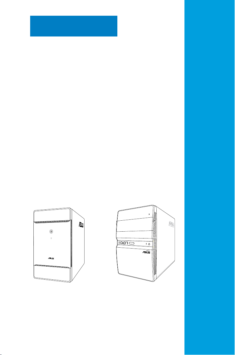
ASUS PC (Desktop Barebone)
T3-P5G43 T4-P5G43*
* Only some of the T4 models have the
Time and IR LED display.

E4260
First Edition
November 2008
Copyright © 2008 ASUSTeK Computer Inc. All Rights Reserved.
No part of this manual, including the products and software described in it, may be reproduced,
transmitted, transcribed, stored in a retrieval system, or translated into any language in any form or by any
means, except documentation kept by the purchaser for backup purposes, without the express written
permission of ASUSTeK Computer Inc. (“ASUS”).
Product warranty or service will not be extended if: (1) the product is repaired, modied or altered, unless
such repair, modication of alteration is authorized in writing by ASUS; or (2) the serial number of the
product is defaced or missing.
ASUS PROVIDES THIS MANUAL “AS IS” WITHOUT WARRANTY OF ANY KIND, EITHER EXPRESS
OR IMPLIED, INCLUDING BUT NOT LIMITED TO THE IMPLIED WARRANTIES OR CONDITIONS OF
MERCHANTABILITY OR FITNESS FOR A PARTICULAR PURPOSE. IN NO EVENT SHALL ASUS, ITS
DIRECTORS, OFFICERS, EMPLOYEES OR AGENTS BE LIABLE FOR ANY INDIRECT, SPECIAL,
INCIDENTAL, OR CONSEQUENTIAL DAMAGES (INCLUDING DAMAGES FOR LOSS OF PROFITS,
LOSS OF BUSINESS, LOSS OF USE OR DATA, INTERRUPTION OF BUSINESS AND THE LIKE),
EVEN IF ASUS HAS BEEN ADVISED OF THE POSSIBILITY OF SUCH DAMAGES ARISING FROM ANY
DEFECT OR ERROR IN THIS MANUAL OR PRODUCT.
SPECIFICATIONS AND INFORMATION CONTAINED IN THIS MANUAL ARE FURNISHED FOR
INFORMATIONAL USE ONLY, AND ARE SUBJECT TO CHANGE AT ANY TIME WITHOUT NOTICE,
AND SHOULD NOT BE CONSTRUED AS A COMMITMENT BY ASUS. ASUS ASSUMES NO
RESPONSIBILITY OR LIABILITY FOR ANY ERRORS OR INACCURACIES THAT MAY APPEAR IN THIS
MANUAL, INCLUDING THE PRODUCTS AND SOFTWARE DESCRIBED IN IT.
Products and corporate names appearing in this manual may or may not be registered trademarks or
copyrights of their respective companies, and are used only for identication or explanation and to the
owners’ benet, without intent to infringe.
ii

Contents
Notices ......................................................................................................... vi
Safety information .....................................................................................
About this guide .......................................................................................
System package contents ...........................................................................
Chapter 1: System introduction
1.1 Welcome! ...................................................................................... 1-2
1.2 Front panel ...................................................................................
1.2.1 T3-P5G43 front panel .....................................................
1.2.2 T4-P5G43 front panel .....................................................
1.3 Rear panel .....................................................................................
1.4 Internal components ....................................................................
Chapter 2: Basic installation
2.1 Preparation ................................................................................... 2-2
2.2 Before you proceed .....................................................................
2.3 Removing the cover .....................................................................
2.4 Power supply unit ........................................................................
2.5 CPU installation ............................................................................
2.5.1 Installing the CPU ...........................................................
2.5.2 Installing CPU fan and heatsink assembly ......................
2.6 Installing a DIMM ..........................................................................
2.6.1 Memory congurations ....................................................
2.6.2 DIMM installation ..........................................................
2.7 Installing an expansion card .....................................................
2.7.1 Expansion slots .............................................................
2.7.2 Expansion card installation ...........................................
2.8 Installing an optical drive ..........................................................
2.9 Installing a Serial ATA disk drive ..............................................
2.10 Replacing the power supply unit ..............................................
Voltage selector ............................................................................ 2-17
2.11 Replacing the cover ...................................................................
2-12
2-13
2-13
2-14
2-15
2-16
2-17
2-18
vii
viii
x
1-2
1-2
1-4
1-6
1-8
2-2
2-3
2-4
2-5
2-5
2-7
2-8
2-8
Chapter 3: Starting up
3.1 Installing an operating system ................................................... 3-2
3.2 Powering up ..................................................................................
3.3 Support CD information ..............................................................
3-2
3-3
iii

Contents
3.3.1 Running the support CD ................................................. 3-3
3.3.2 Drivers menu ...................................................................
3.3.3 Utilities menu ..................................................................
3.3.4 ASUS contact information ...............................................
3.4 Software information ...................................................................
ASUS Express Gate ....................................................................... 3-7
Chapter 4: Motherboard info
4.1 Introduction .................................................................................. 4-2
4.2 Motherboard layout ......................................................................
4.3 Jumpers ........................................................................................ 4-3
4.4 Connectors ................................................................................... 4-5
Chapter 5: BIOS setup
5.1 Managing and updating your BIOS ............................................ 5-2
5.1.1 Creating a bootable oppy disk .......................................
5.1.2 ASUS EZ Flash 2 utility ...................................................
5.1.3 AFUDOS utility ................................................................
5.1.4 ASUS CrashFree BIOS 3 utility ......................................
5.1.5 ASUS Update utility ........................................................
5.2 BIOS setup program ..................................................................
5.2.1 BIOS menu screen ........................................................
5.2.2 Menu bar .......................................................................
5.2.3 Navigation keys .............................................................
5.2.4 Menu items ...................................................................
5.2.5 Sub-menu items ............................................................
5.2.6 Conguration elds .......................................................
5.2.7 Pop-up window .............................................................
5.2.8 Scroll bar .......................................................................
5.2.9 General help .................................................................
5.3 Main menu ..................................................................................
5.3.1 System Time .................................................................
5.3.2 System Date .................................................................
5.3.3 SATA1, SATA2, SATA3, and SATA4 ..............................
5.3.4 Congure SATA as ........................................................
5.3.5 System Information .......................................................
3-4
3-5
3-6
3-7
4-2
5-2
5-3
5-4
5-6
5-8
5-11
5-12
5-12
5-12
5-13
5-13
5-13
5-13
5-13
5-13
5-14
5-14
5-14
5-15
5-16
5-17
iv

Contents
5.4 Advanced menu ......................................................................... 5-18
5.4.1 CPU Conguration ........................................................
5.4.2 Chipset ..........................................................................
5.4.3 Onboard Devices Conguration ....................................
5.4.4 USB Conguration ........................................................
5.5 Power menu ................................................................................
5.5.1 Suspend Mode .............................................................. 5-24
5.5.2 Repost Video on S3 Resume ........................................
5.5.3 ACPI 2.0 Support ..........................................................
5.5.4 ACPI APIC Support .......................................................
5.5.5 APM Conguration ........................................................
5.5.6 Hardware Monitor .........................................................
5.6 Boot menu ..................................................................................
5.6.1 Boot Device Priority ......................................................
5.6.2 Boot Settings Conguration ..........................................
5.6.3 Security .........................................................................
5.7 Tools menu .................................................................................
5.7.1 ASUS EZ Flash 2 ..........................................................
5.7.2 Express Gate ................................................................
5.7.3 LED Poster Conguration .............................................
5.8 Exit menu ....................................................................................
5-18
5-20
5-21
5-22
5-24
5-24
5-24
5-25
5-25
5-27
5-28
5-28
5-29
5-30
5-32
5-32
5-33
5-34
5-35
Appendix
A.1 Powersupplyspecications .......................................................A-2
A.2 Dubug code table .........................................................................
A.3 Using the Remote Control (optional) .........................................
®
A.4 Integrating AHCI driver to Windows
XP installation ...............A-5
A-2
A-3
v

Notices
Federal Communications Commission Statement
This device complies with Part 15 of the FCC Rules. Operation is subject to the
following two conditions:
•
This device may not cause harmful interference, and
•
This device must accept any interference received including interference that
may cause undesired operation.
This equipment has been tested and found to comply with the limits for a
Class B digital device, pursuant to Part 15 of the FCC Rules. These limits are
designed to provide reasonable protection against harmful interference in a
residential installation. This equipment generates, uses and can radiate radio
frequency energy and, if not installed and used in accordance with manufacturer’s
instructions, may cause harmful interference to radio communications. However,
there is no guarantee that interference will not occur in a particular installation. If
this equipment does cause harmful interference to radio or television reception,
which can be determined by turning the equipment off and on, the user is
encouraged to try to correct the interference by one or more of the following
measures:
•
Reorient or relocate the receiving antenna.
•
Increase the separation between the equipment and receiver.
•
Connect the equipment to an outlet on a circuit different from that to which the
receiver is connected.
•
Consult the dealer or an experienced radio/TV technician for help.
The use of shielded cables for connection of the monitor to the graphics card is
required to assure compliance with FCC regulations. Changes or modications
to this unit not expressly approved by the party responsible for compliance
could void the user’s authority to operate this equipment.
Canadian Department of Communications Statement
This digital apparatus does not exceed the Class B limits for radio noise emissions
from digital apparatus set out in the Radio Interference Regulations of the
Canadian Department of Communications.
This class B digital apparatus complies with Canadian ICES-003
.
Macrovision Corporation Product Notice
This product incorporates copyright protection technology that is protected by
U.S. patents and other intellectual property rights. Use of this copyright protection
technology must be authorized by Macrovision, and is intended for home and other
limited viewing uses only unless otherwise authorized by Macrovision. Reverse
engineering or disassembly is prohibited.
vi

Safety information
Electrical safety
•
To prevent electrical shock hazard, disconnect the power cable from the
electrical outlet before relocating the system.
•
When adding or removing devices to or from the system, ensure that the power
cables for the devices are unplugged before the signal cables are connected.
•
If the power supply is broken, do not try to x it by yourself. Contact a qualied
service technician or your retailer.
Operation safety
•
Before installing devices into the system, carefully read all the documentation
that came with the package.
•
Before using the product, ensure that all cables are correctly connected and
the power cables are not damaged. If you detect any damage, contact your
dealer immediately.
•
To avoid short circuits, keep paper clips, screws, and staples away from
connectors, slots, sockets and circuitry.
•
Avoid dust, humidity, and temperature extremes. Do not place the product in
any area where it may become wet. Place the product on a stable surface.
•
When using the product, do not block any air inlet/outlet in the chassis.
•
The maximum environmental temperature is 35ºC.
•
If you encounter technical problems with the product, contact a qualied
service technician or your retailer.
Lithium-Ion Battery Warning
CAUTION: Danger of explosion if battery is incorrectly replaced. Replace
only with the same or equivalent type recommended by the manufacturer.
Dispose of used batteries according to the manufacturer’s instructions.
VORSICHT: Explosionsgetahr bei unsachgemäßen Austausch der Batterie.
Ersatz nur durch denselben oder einem vom Hersteller empfohlenem
ähnljchen Typ. Entsorgung gebrauchter Batterien nach Angaben des
Herstellers.
LASER PRODUCT WARNING
CLASS 1 LASER PRODUCT
vii

About this guide
Audience
This guide provides general information and installation instructions about ASUS
T-P5G43 barebone system. This guide is intended for experienced users and
integrators with hardware knowledge of personal computers.
How this guide is organized
This guide contains the following parts:
1. Chapter 1: System introduction
This chapter gives a general description of ASUS T-P5G43. The chapter lists
the system features, including introduction on the front and rear panel, and
internal components.
2. Chapter 2: Basic installation
This chapter provides step-by-step instructions on how to install components
in the system.
3. Chapter 3: Starting up
This chapter helps you power up the system and install drivers and utilities
from the support CD.
4. Chapter 4: Motherboard info
This chapter gives information about the motherboard that comes with the
system. This chapter includes the motherboard layout, jumper settings, and
connector locations.
5. Chapter 5: BIOS information
This chapter tells how to change system settings through the BIOS Setup
menus and describes the BIOS parameters.
6. Appendix
The Appendix includes the power supply unit specication, remote control for
this system, as well as the integrating Windows® XP installation.
viii

Conventions used in this guide
WARNING: Information to prevent injury to yourself when trying to
complete a task.
CAUTION: Information to prevent damage to the components when
trying to complete a task.
IMPORTANT: Instructions that you MUST follow to complete a task.
NOTE: Tips and additional information to aid in completing a task.
Wheretondmoreinformation
Refer to the following sources for additional information and for product and
software updates.
1. ASUS Websites
The ASUS websites worldwide provide updated information on ASUS
hardware and software products. Refer to the ASUS contact information.
2. Optional Documentation
Your product package may include optional documentation, such as warranty
yers, that may have been added by your dealer. These documents are not
part of the standard package.
ix
System package contents
Check your T-P5G43 system package for the following items.
If any of the items is damaged or missing, contact your retailer immediately.
Item description
1. ASUS T-P5G43 barebone system with
•
ASUS motherboard
•
250 W PFC power supply unit
•
Front I/O card and 3-in-1 storage card reader
2. Cables
•
AC power cord
•
ATA cable
•
Serial ATA cable
•
Serial ATA power cable
3. Support CD
4. Installation Manual
5. Optional items
•
Remote control
x

Chapter 1
This chapter gives a general
description of ASUS T-P5G43. The
chapter lists the system features
including introduction on the front and
rear panel, and internal components.
T3-P5G43 T4-P5G43*
* Only some of the T4 models have the
Time and IR LED display.
System introduction
1.1 Welcome!
Thank you for buying an ASUS T-P5G43!
ASUS T-P5G43 is an all-in-one barebone system with a versatile home
entertainment feature.
The system comes in a stylish mini-tower casing, and powered by an ASUS
motherboard that supports the Intel® processor in the 775-land package with
800/1066/1333 MHz FSB and up to 8 GB system memory.
With audio functions, extensive connectivity, and Gigabit LAN capability, the
T-P5G43 is designed for the sophisticated.
With these and many more, the T-P5G43 denitely delivers the cutting edge
technology for your computing and multimedia needs!
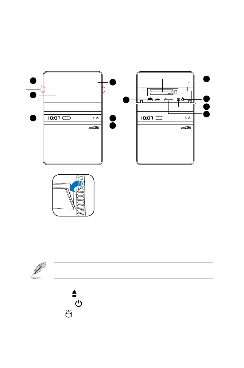
1.2 Front panel
The front panel includes the system control button, system LEDs, and LED panel.
The storage card reader slots, and several I/O ports are located inside the front
panel cover.
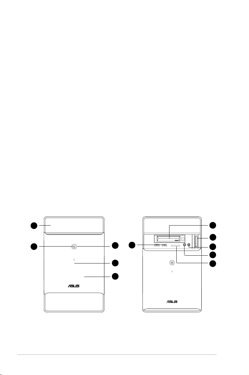
1.2.1 T3-P5G43 front panel
External
1
6
2
1-2 Chapter 1: System introduction
3
4
5
Internal
7
8
9
10
11
1. Drive door. Open this door to access the optical drive.
2.0
2. Power button . Press this button to turn the system on/off.
3. HDD LED . This LED lights up when data is reading from or writing to the
hard disk drive. (for Black Bezel)
4. HDD LED . This LED lights up when data is reading from or writing to the
hard disk drive. (for Silver Bezel)
5. Front panel I/O cover. Push downwards to open the front panel cover and
display the input/output ports.
6. USB 2.0 ports
. These Universal Serial Bus 2.0 (USB 2.0) ports are
available for connecting USB 2.0 devices such as a mouse, printer, scanner,
camera, PDA, and others.
7. Portable Hard Disk Drive (Optional).
• Enable AHCI mode to support the hot-plug feature. For Windows® Vista
system, enable AHCI mode from BIOS setup before installing the operation
system. Refer to page 5-16 for details. For Windows® XP system, refer to
the section A.4 Integrating AHCI Driver to Windows® XP installation for
details.
• If you have installed an empty Portable Hard Disk Drive to the system, eject
it before turning on the system. This is to prevent the system from slowing
down.
8. Eject button . Press this button to eject the optical drive.
9. Microphone port . This Mic (pink) port connects a microphone.
10. Headphone port . This port connects a headphone with a stereo mini-
plug.
11. Secure Digital™/MultimediaCard/Memory Stick (MS) slot
. This slot is
for a Secure Digital™/MultimediaCard/Memory Stick storage card.
The information provided is intended as a general guide for reference.
Specications depend on the barebone system you purchased.
1-3ASUS T-P5G43
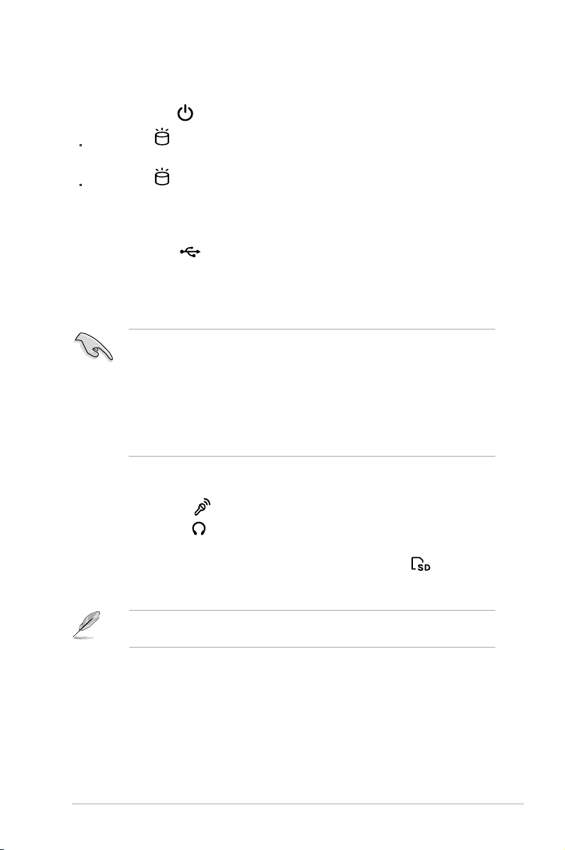
1.2.2 T4-P5G43 front panel
External
1
2
3
4
7
5
6
Internal
8
9
10
11
1. Drive door. Open this door to access the optical drive.
2. Front panel I/O cover. Push downwards to open the front panel cover and
display the input/output ports.
3. Time and IR LED display
(optional)
When your PC boots up, it displays the time of the Operating System. There
may be an advance or a late than the current time.
4. Eject button . Press this button to eject the optical drive.
5. Power button . Press this button to turn the system on/off.
6. HDD LED
. This LED lights up when data is reading from or writing to the
hard disk drive.
1-4 Chapter 1: System introduction
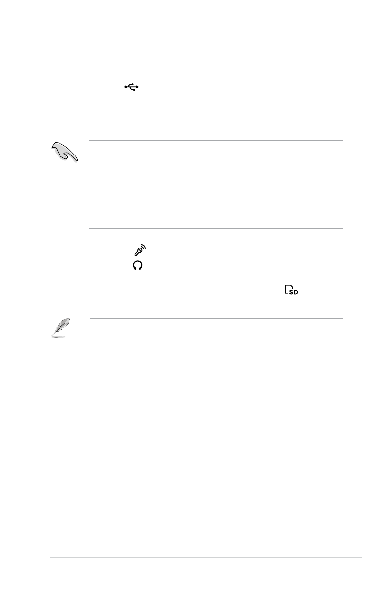
7. USB 2.0 ports
2.0
. These Universal Serial Bus 2.0 (USB 2.0) ports are
available for connecting USB 2.0 devices such as a mouse, printer, scanner,
camera, PDA, and others.
8. Portable Hard Disk Drive (Optional).
• Enable AHCI mode to support the hot-plug feature. For Windows® Vista
system, enable AHCI mode from BIOS setup before installing the operation
system. Refer to page 5-16 for details. For Windows® XP system, refer to
the section A.4 Integrating AHCI Driver to Windows® XP installation for
details.
• If you have installed an empty Portable Hard Disk Drive to the system, eject
it before turning on the system. This is to prevent the system from slowing
down.
9. Microphone port . This Mic (pink) port connects a microphone.
10. Headphone port . This port connects a headphone with a stereo mini-
plug.
11. Secure Digital™/MultimediaCard/Memory Stick (MS) slot
. This slot is
for a Secure Digital™/MultimediaCard/Memory Stick storage card.
The information provided is intended as a general guide for reference.
Specications are subject to the barebone system you purchased.
1-5ASUS T-P5G43
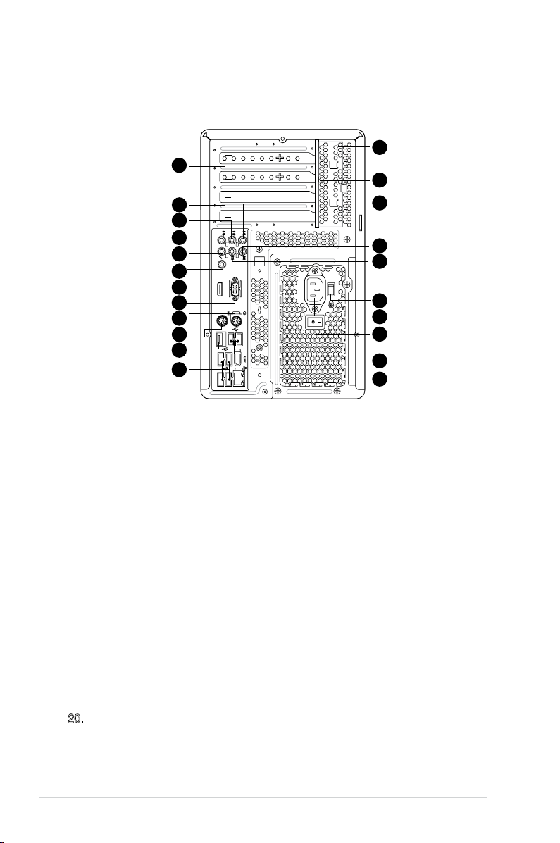
1.3 Rear panel
The system rear panel includes the power connector and several I/O ports that
allow convenient connection of devices.
24
12
25
13
14
15
16
17
18
19
20
21
22
23
T3-P5G43/T4-P5G43
12. Expansion slot covers. Remove these covers when installing expansion
cards.
13. Expansion slots. Use this slot when installing expansion card.
14. Rear speaker Out port (black). This port connects the rear speakers on a
4-channel, 6-channel, or 8-channel audio conguration.
15. Side Speaker Out port (gray). This port connects the side speakers in an
8-channel audio conguration.
16. Microphone port (pink). This Microphone port connects a microphone.
17. Coaxial S/PDIF Out port.
This port connects an external audio output device
via a coaxial S/PIF cable
18. HDMI port.
This port is for a High-Denition Multimedia Interface (HDMI)
connector, and is HDCP compliant allowing playback of HD DVD, Blu-Ray
and other protected content.
19. Video Graphics Adapter (VGA) port.
This 15-pin port is for a VGA monitor
or other VGA-compatible devices.
20. PS/2 mouse port (green). This green 6-pin connector is for a PS/2 mouse.
21. PS/2 keyboard port (purple). This purple 6-pin connector is for a PS/2
keyboard.
26
27
28
29
30
31
32
33
1-6 Chapter 1: System introduction

22. External SATA port. This port connects to an external Serial ATA hard disk
drive.
DO NOT insert different connectors into the external SATA port.
23. USB 2.0 ports. These Universal Serial Bus 2.0 (USB 2.0) ports are available
for connecting USB 2.0 devices such as a mouse, printer, scanner, camera,
PDA, and others.
24. Chassis vent. This vent is for the fan that provides ventilation inside the
system chassis.
25. Expansion card lock. This lock secures installed expansion cards. See
page 2-14 for details.
26. Center & woofer speakers (orange). This port connects the center/
subwoofer speakers.
27. Line In port (light blue). This Line In port connects a tape player or other
audio sources. In 6-channel mode, the function of this port becomes
Surround output.
28. Line Out port (lime). This Line Out port connects a headphone or a speaker.
In 4/6-channel mode, the function of this port becomes Front Speaker Out.
29. Voltage selector. This switch allows you to adjust the system input voltage
according to the voltage supply in your area.
30. Power connector. This connector is for a power cable and plug.
31. Power switch. This switch allows you to turn your PC on/off.
32. 6-pin IEEE 1394a port . This port provides high-speed connectivity for IEEE
1394a-compliant audio/video devices, storage peripherals, and other PC
devices.
33. LAN port.
This port allows connection to a Local Area Network (LAN) through
a network hub.
1-7ASUS T-P5G43
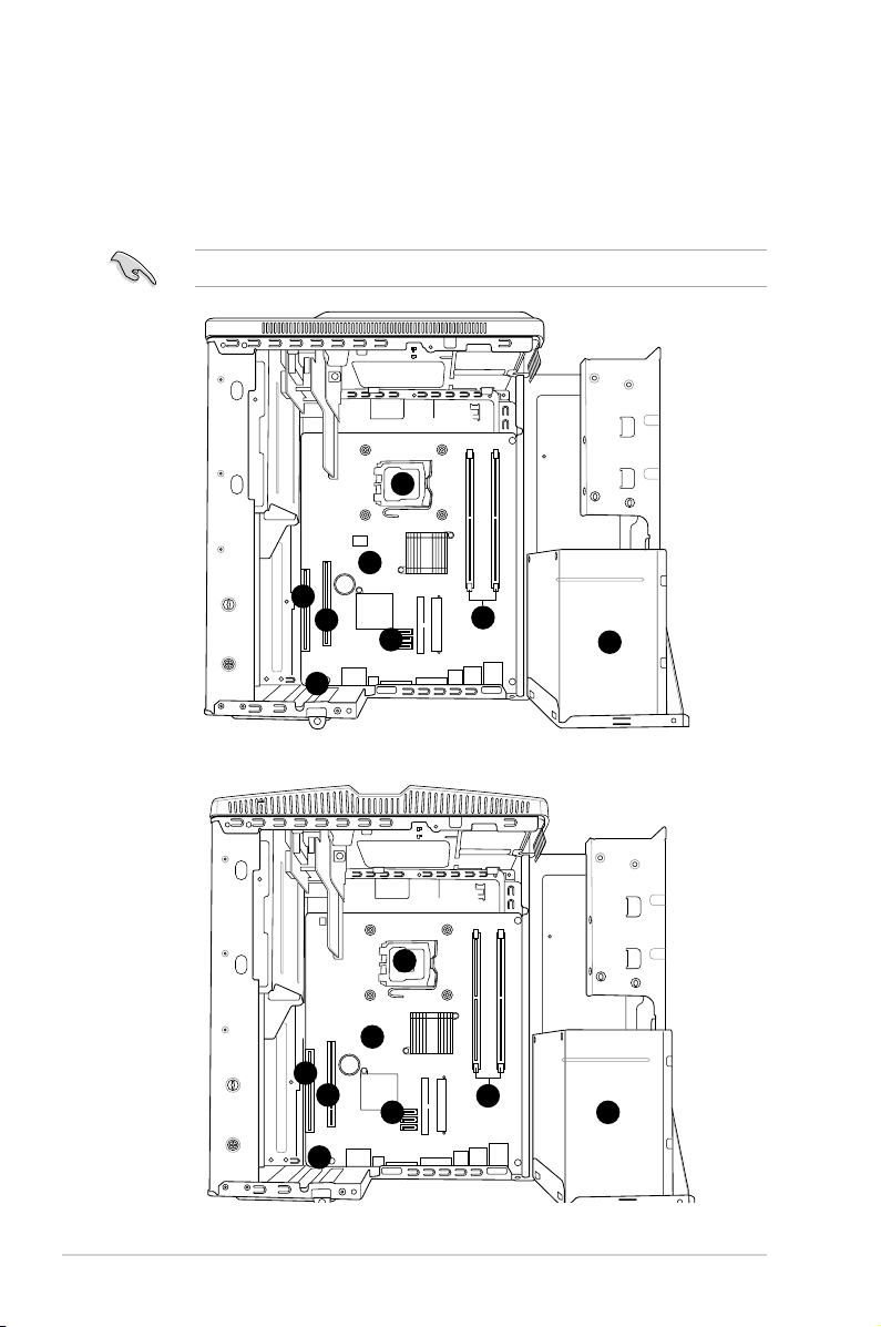
1.4 Internal components
The illustration below is the internal view of the system when you remove the top
cover and the power supply unit. The installed components are labeled for your
reference. Proceed to Chapter 2 for instructions on installing additional system
components.
The illustration shows an open chassis lifted at a 90o angle.
2
1
6
5
4
7
T3-P5G43
3
8
2
1
6
7
5
4
T4-P5G43
3
8
1-8 Chapter 1: System introduction

1. ASUS motherboard
2. LGA775 socket with PnP cap
3. DIMM sockets for DDR2
4. Serial ATA connectors
5. PCI Express™ x16 slot for discrete graphics card
6. PCI slot
7. Expansion card slot
8. Power supply unit
1-9ASUS T-P5G43

1-10 Chapter 1: System introduction
Chapter 2
This chapter provides step-by-step
instructions on how to install
components in the system.
T3-P5G43 T4-P5G43*
* Only some of the T4 models have the
Time and IR LED display.
Basic installation
2.1 Preparation
P5Q18L
SB_PWR
ON
Standy Power Powered Off
OFF
P5Q18L Onboard LED
Before you proceed, ensure that you have all the components you plan to install in
the system.
Basic components to install
1. Central Processing Unit (CPU)
2. DDR2 Dual Inline Memory Module (DIMM)
3. Expansion card(s)
4. Hard disk drive
5. Optical drive
Tool
Philips (cross) screw driver
2.2 Before you proceed
Take note of the following precautions before you install components into the
system.
•
Use a grounded wrist strap or touch a safely grounded object or a metal
object, such as the power supply case, before handling components to
avoid damaging them due to static electricity.
•
Hold components by the edges to avoid touching the ICs on them.
•
Whenever you uninstall any component, place it on a grounded antistatic
pad or in the bag that came with the component.
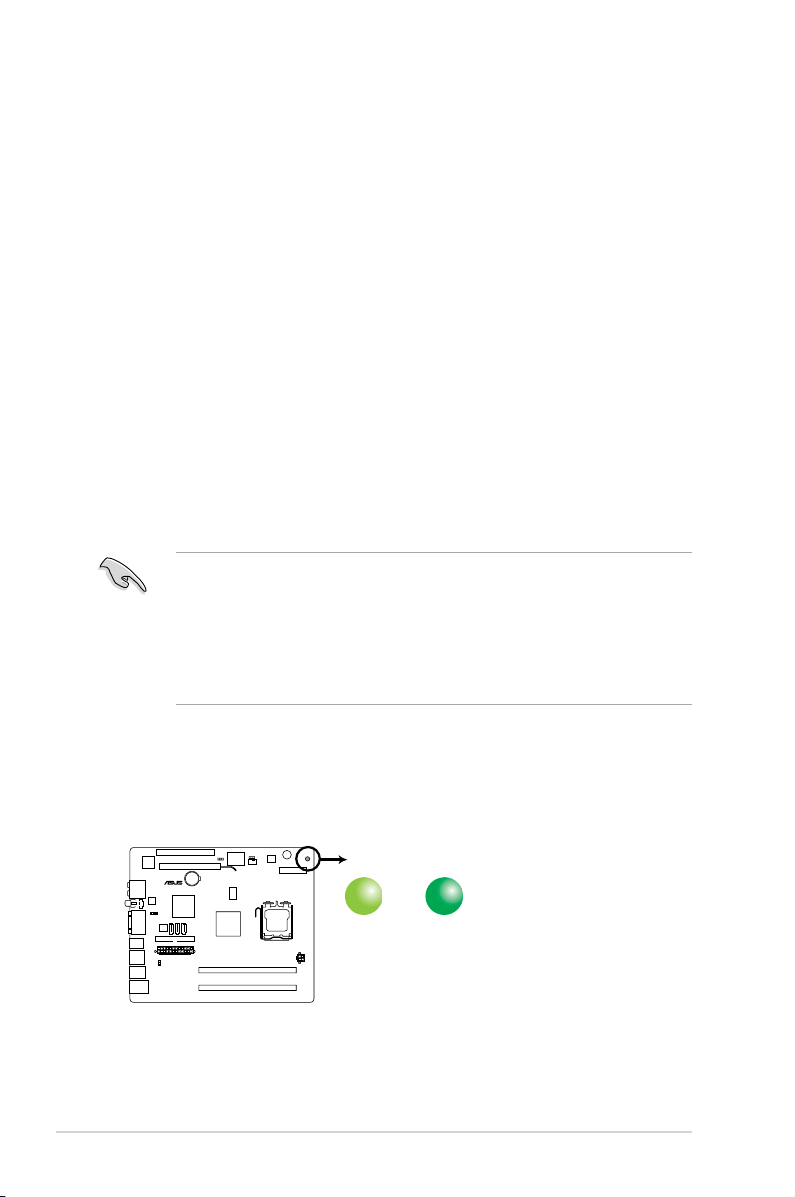
The motherboard comes with an onboard standby power LED. This LED lights
up to indicate that the system is ON, in sleep mode or in soft-off mode, and not
powered OFF. Unplug the power cable from the power outlet and ensure that the
standby power LED is OFF before installing any system component.
2-2 Chapter 2: Basic installation
2.3 Removing the cover
REAR
S P K
LINE
IN
FRONT
MIC IN
SIDE
S P K
C T R
BASS
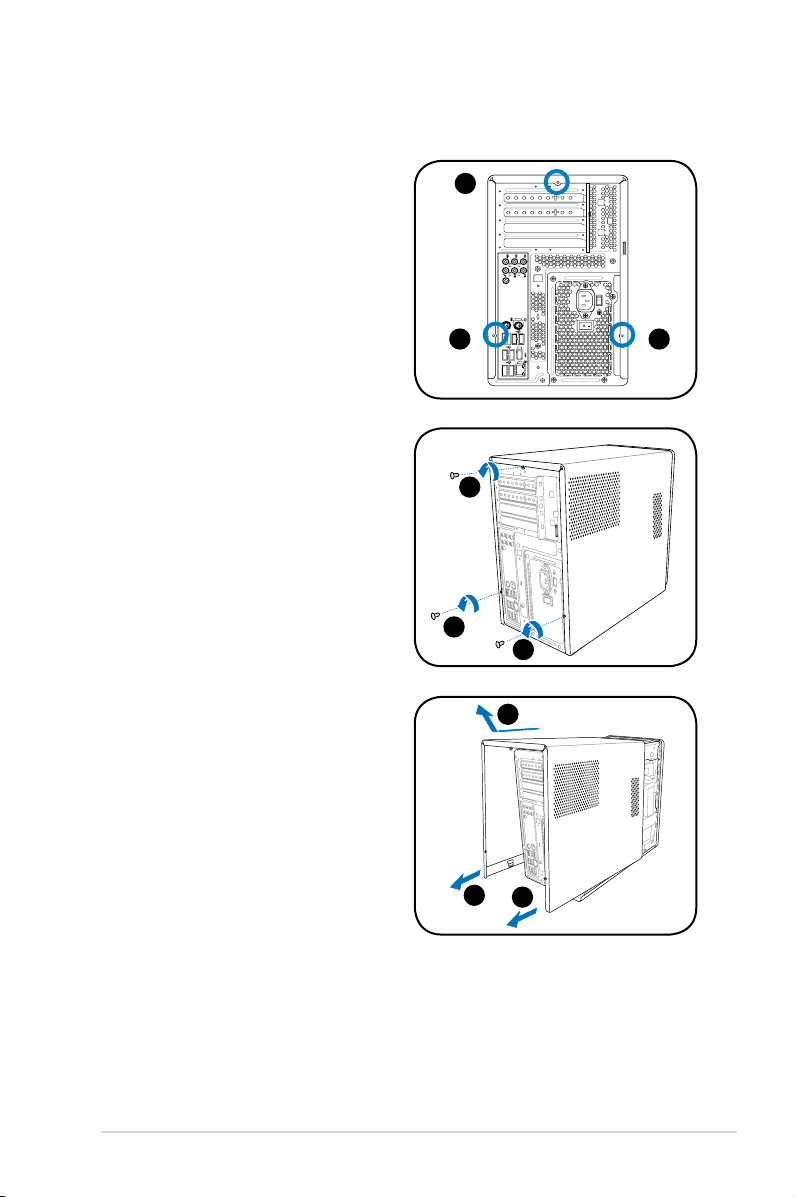
To remove the cover:
1. On the rear panel, locate the three
screws that secure the cover to the
chassis.
2. Use a Phillips screw driver to
remove the cover screws. Keep the
screws for later use.
3. Slightly pull the cover toward the
rear panel until the side tabs are
disengaged from the chassis.
4. Lift the cover, then set aside.
1
1 1
2
2
2
4
3
3
2-3ASUS T-P5G43
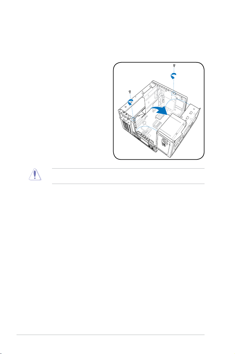
2.4 Power supply unit
You need to turn over the power supply unit (PSU) section on the side before you
can install a central processing unit (CPU) and other system components.
To turn over the PSU:
1. Lay the system chassis on
its side on a at and stable
surface.
2. Locate and remove the two
screws that secures the PSU to
the chassis.
3. Lift the PSU in the direction of
the arrow to a 90º angle.
When removing the PSU, ensure to hold or support it rmly. The unit may
accidentally drop and damage other system components.
2-4 Chapter 2: Basic installation
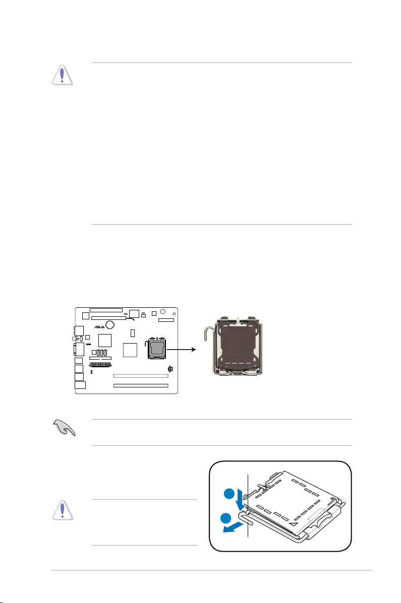
2.5 CPU installation
P5Q18L
P5Q18L CPU socket 775
• Your boxed Intel® LGA775 processor package should come with installation
instructions for the CPU, heatsink, and the retention mechanism. If the
instructions in this section do not match the CPU documentation, follow the
latter.
•
Check your motherboard to ensure that the PnP cap is on the CPU socket
and the socket contacts are not bent. Contact your retailer immediately if
the PnP cap is missing, or if you see any damage to the PnP cap/socket
contacts/motherboard components. ASUS will shoulder the cost of repair
only if the damage is shipment/transit-related.
•
Keep the cap after installing the motherboard. ASUS will process Return
Merchandise Authorization (RMA) requests only if the motherboard comes
with the cap on the LGA775 socket.
• The product warranty does not cover damage to the socket contacts
resulting from incorrect CPU installation/removal, or misplacement/loss/
incorrect removal of the PnP cap.
2.5.1 Installing the CPU
To install a CPU:
1. Locate the CPU socket on the motherboard.
Before installing the CPU, ensure that the socket box is facing towards you and
the load lever is on your left.
2. Press the load lever with your thumb
(A), then move it to the left (B) until
it is released from the retention tab.
To prevent damage to the
socket pins, do not remove
the PnP cap unless you are
installing a CPU.
Retention tab
A
B
Load lever
2-5ASUS T-P5G43
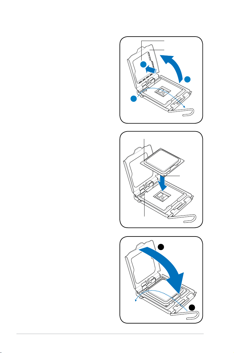
3. Lift the load lever in the direction of
the arrow to a 135º angle.
4. Lift the load plate with your thumb
and forenger to a 100º angle (4A),
then push the PnP cap from the
load plate window to remove (4B).
PnP cap
Load plate
4B
4A
3
5. Position the CPU over the socket,
ensuring that the gold triangle is on
the bottom-left corner of the socket
then t the socket alignment key
into the CPU notch.
6. Close the load plate (A), then push
the load lever (B) until it snaps into
the retention tab.
CPU notch
Gold
triangle
mark
Alignment key
A
B
2-6 Chapter 2: Basic installation
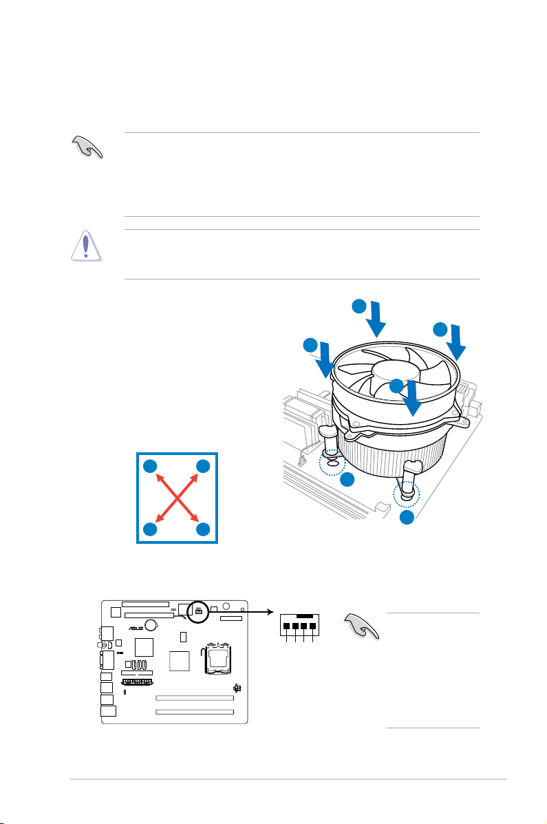
2.5.2 Installing CPU fan and heatsink assembly
P5Q18L
CPU_FAN
CPU FAN PWM
CPU FAN IN
CPU FAN PWR
GND
P5Q18L CPU fan connector
The Intel® LGA775 processor requires a specially designed heatsink and fan
assembly to ensure optimum thermal condition and performance.
• When you buy a boxed Intel® processor, the package
includes the CPU fan and heatsink assembly. If you buy a CPU separately,
ensure that you use only Intel®-certied multi-directional heatsink and fan.
®
• Your Intel
and requires no tool to install.
If you purchased a separate CPU heatsink and fan assembly, ensure that the
Thermal Interface Material is properly applied to the CPU heatsink or CPU
before you install the heatsink and fan assembly.
LGA775 heatsink and fan assembly comes in a push-pin design
To install the CPU heatsink and fan:
1. Place the heatsink on top of the
installed CPU, ensuring that the four
B
A
B
fasteners match the holes on the
motherboard.
2. Push down two fasteners at a time in
A
a diagonal sequence to secure the
heatsink and fan assembly in place.
A
B
B
1
1
A
3. When the fan and heatsink assembly is in place, connect the CPU fan cable
to the connector on the motherboard.
Do not forget to
connect the CPU
fan connector!
Hardware
monitoring errors
can occur if you
fail to plug this
connector.
2-7ASUS T-P5G43
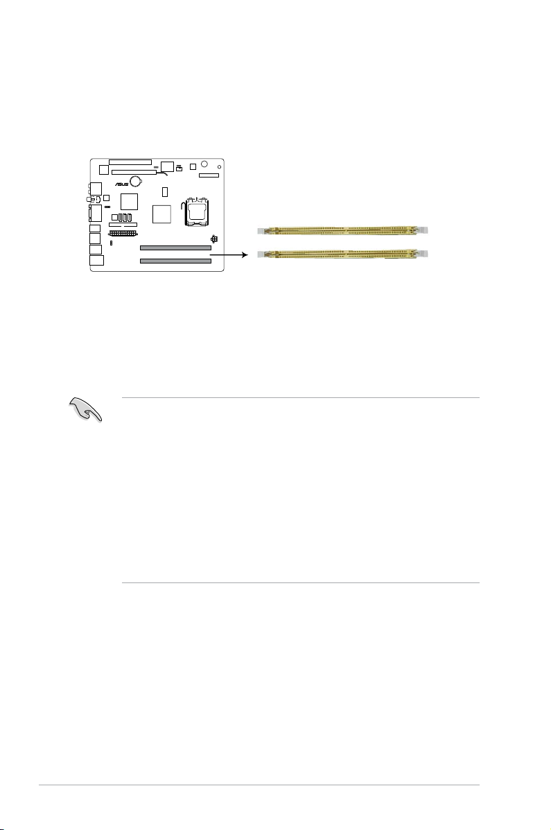
2.6 Installing a DIMM
P5Q18L
P5Q18L 240-pin DDR2 DIMM sockets
DIMM_A1
DIMM_B1
The system motherboard comes with two Double Data Rate 2 (DDR2) Dual Inline
Memory Module (DIMM) sockets (DIMM_A1 and DIMM_B1).
The following gure illustrates the location of the sockets:
2.6.1 Memorycongurations
You may install up to 8 GB system memory using 512 MB, 1 GB, 2GB, and 4GB
DDR2 DIMMs.
• You may install varying memory sizes in Channel A and Channel B. The
system maps the total size of the lower-sized channel for the dual-channel
conguration. Any excess memory from the higher-sized channel is then
mapped for single-channel operation.
• Always install DIMMs with the same CAS latency. For optimum
compatibility, we recommend that you obtain memory modules from the
same vendor.
• Due to the memory address limitation on 32-bit Windows OS, when
you install 4GB or more memory on the motherboard, the actual usable
memory for the OS can be about 3GB or less. For effective use of memory,
we recommend that you install a 64-bit Windows OS when having 4GB or
more memory installed on the motherboard.
2-8 Chapter 2: Basic installation
DDR2(667MHz)QualiedVendorsList
Vendor Part No. Size Chip No. C/L Brand
Apacer 78.A1G9O.9K4 2GB DS AM4B5808CQJS7E N/A APACER • •
CORSAIR VS1GB667D2 1GB DS 64M8CFEG N/A N/A • •
crucial BL12864AA663.16FD 1GB DS Heat-Sink Package 3 N/A • •
crucial BL12864AL664.16FD 1GB DS Heat-Sink Package 3 N/A • •
GEIL GX21GB5300SX 1GB DS Heat-Sink Package 3-4-4-8 N/A • •
GEIL GX22GB5300LX 2GB DS Heat-Sink Package 5-5-5-15 N/A • •
GEIL GX24GB5300LDC 4GB(Kit of 2) DS Heat-Sink Package 5-5-5-15 N/A • •
Hynix HYMP112U64CP8-Y5 1GB SS HY5PS1G831CFP-Y5 5 Hynix • •
Hynix HYMP 512U64CP8-Y5 1GB DS HY5PS12821CFP-Y5 5 Hynix • •
KINGSTON KVR667D2E5/1G 1GB DS E5108AGBG-6E-E(ECC) N/A ELPIDA • •
KINGSTON KVR667D2N5/1G 1GB DS E5108AGBG-6E-E N/A KINGSTON • •
KINGSTON KVR667D2N5/1G 1GB DS E5108AJBG-8E-E N/A ELPIDA • •
KINGSTON KVR667D2N5/1G 1GB DS HY5PS12821CFP-Y5 N/A Hynix • •
KINGSTON KVR667D2N5/2G 2GB DS E1108AB-6E-E N/A ELPIDA • •
KINGSTON KVR667D2N5/2G 2GB DS HY5PS1G831CFP-Y5 N/A Hynix • •
OCZ OCZ26671024V 1GB SS RC1GT084CA0-53EC 5 Ramos • •
PSC AL7E8E63J-6E1 1GB DS A3R12E3JFF719A9T02 5 PSC • •
Qimonda HYS64T256020EU-3S-C2 2GB DS HYB18T1GB00C2F-3S 555-12 Qimonda • •
SAMSUNG M378T2953EZ3-CE6 1GB DS K4T51083QE 5 SAMSUNG • •
Super Talent T6UB1GC5 1GB DS Heat-Sink Package 5 N/A • •
Transcend JM667QLU-2G 2GB DS TQ243ECF8 5 Transcend • •
Aeneon AET760UD00-30DB97X 1GB DS AET93R30DB 5 AENEON • •
Aeneon AET860UD00-30DB08X 2GB DS AET03F30DB 5 AENEON • •
Asint SLY2128M8-J6E 1GB SS DDRII1208-6E N/A Asint • •
Kingbox N/A 1GB SS EPD2128082200E-4 N/A N/A • •
Kingbox N/A 1GB DS EPD264082200E-4 N/A N/A • •
Kingbox N/A 1GB DS EPD264082200N-4 N/A Kingbox • •
MDT M924-667-16 1GB DS 18D 51280D-30646E 4 MDT • •
Patriot PSD21G6672 1GB DS PM64M8D2BU-3PAC 5 Patriot • •
UMAX U2S12D30TP-6E 1GB DS D46701GP3-63BJU N/A UMAX • •
DIMM support
A* B*
2-9ASUS T-P5G43

DDR2(800MHz)QualiedVendorsList
Vendor Part No. Size
A-DATA M2OAD6H3J4171Q1E52 2GB DS AD20908A8A-25EG N/A A-DATA • •
Apacer 78.01GA0.9K5 1GB SS AM4B5808CQJS8E N/A APACER • •
Apacer 78.A1GA0.9K4 2GB DS AM4B5808CQJS8E 5 APACER • •
CORSAIR “BoxP/N:TWIN2X4096-6400C4DHX
(CM2X2048-6400C4DHX)”
CORSAIR “BoxP/N:TWIN2X4096-6400C5DHX
(CM2X2048-6400C5DHX)”
Crucial BL12864AA804.16FD 1GB DS Heat-Sink Package 4 N/A • •
ELPIDA EBE10EE8ABFA-8E-E 1GB SS E1108AB-8E-E(ECC) 5 ELPIDA • •
G.SKILL F2-6400CL4D-2GBHK 1GB DS Heat-Sink Package N/A N/A • •
G.SKILL F2-6400CL4D-2GBPK 1GB DS Heat-Sink Package N/A N/A • •
G.SKILL F2-6400CL4D-4GBPK 4GB(Kit of 2) DS Heat-Sink Package 4 N/A • •
G.SKILL F2-6400CL5D-2GBNQ 1GB DS Heat-Sink Package N/A N/A • •
G.SKILL F2-6400CL6D-4GBMQ 4GB(Kit of 2) DS Heat-Sink Package 6 N/A • •
G.SKILL F2-6400CL6D-8GBNQ 8GB(Kit of 2) DS Heat-Sink Package 6-6-6-18 N/A • •
G.SKILL F2-6400PHU2-2GBNR 1GB DS Heat-Sink Package N/A N/A • •
GEIL GB22GB6400C4DC 2GB(Kit of 2) DS GL2L64M088BA30EB N/A N/A • •
GEIL GB22GB6400C5DC 2GB(Kit of 2) DS GL2L64M088BA30EB 5-5-5-15 GEIL • •
GEIL GB24GB6400C4QC 4GB(Kit of 4) DS GL2L64M088BA30EB N/A N/A • •
GEIL GB24GB6400C5DC 4GB(Kit of 2) DS GL2L128M88BA25AB 5-5-5-15 GEIL • •
GEIL GB24GB6400C5QC 4GB(Kit of 2) DS GL2L64M088BA30EB N/A N/A • •
GEIL GB28GB6400C5QC 8GB(Kit of 4) DS GL2L128M88BA25AB N/A N/A • •
GEIL GE22GB800C4DC 2GB(Kit of 2) DS Heat-Sink Package 4-4-4-12 N/A • •
GEIL GE22GB800C5DC 2GB(Kit of 2) DS Heat-Sink Package 5-5-5-15 N/A • •
GEIL GE24GB800C4QC 4GB(Kit of 4) DS Heat-Sink Package N/A N/A • •
GEIL GE24GB800C5QC 4GB(Kit of 4) DS Heat-Sink Package 5-5-5-15 N/A • •
GEIL GX22GB6400C4USC 2GB DS Heat-Sink Package 4-4-4-12 N/A • •
GEIL GX22GB6400UDC 2GB(Kit of 2) DS Heat-Sink Package 4-4-4-12 N/A • •
GEIL GX24GB6400DC 4GB(Kit of 2) DS Heat-Sink Package 5-5-5-15 N/A • •
KINGMAX KLDD48F-ABKI5 1GB DS KKA8FEIBF-HJK-25A N/A KINGMAX • •
KINGMAX KLDE88F-B8KB5 2GB DS KKB8FFBXF-CFA-25A N/A KINGMAX • •
KINGSTON KHX6400D2/ 512 512MB SS Heat-Sink Package N/A N/A • •
KINGSTON KHX6400D2/2G 2GB DS Heat-Sink Package N/A N/A • •
KINGSTON KVR800D2N5/1G 1GB DS E5108AJBG-8E-E N/A ELPIDA • •
KINGSTON KVR800D2N5/1G 1GB DS V59C1 512804QBF25 N/A N/A • •
KINGSTON KVR800D2N5/2G 2GB DS E1108ACBG-8E-E N/A ELPIDA • •
KINGSTON KVR800D2N6/1G 1GB DS E5108AJBG-8E-E 1.8 ELPIDA • •
NANYA NT 512T64U880BY-25C 512MB SS NT5TU64M8BE-25C 5 NANYA • •
NANYA NT1GT64U8HB0BY-25C 1GB DS NT5TU64M8BE-25C 5 NANYA • •
NANYA NT1GT64U8HCOBY-25D 1GB DS NT5TU64M8CE-25D N/A NANYA • •
OCZ OCZ2G8008GK 8GB(Kit of 2) DS Heat-Sink Package 5 N/A • •
OCZ OCZ2P8004GK 4GB(Kit of 2) DS Heat-Sink Package 5-4-4 N/A • •
OCZ OCZ2P800R22GK 2GB(Kit of 2) DS Heat-Sink Package 4 N/A • •
Qimonda HYS64T 512020EU-2.5-A 4GB DS HYB18T2G800AF-2.5 6 QIMONDA • •
Qimonda HYS64T 512020EU-25F-A 4GB DS HYB18T2G800AF-25F 5 QIMONDA • •
4GB(Kit of 2) DS Heat-Sink Package 4-4-4-12 N/A • •
4GB(Kit of 2) DS Heat-Sink Package N/A N/A • •
SS/
Chip No. C/L Brand
DS
DIMM support
A* B*
continued on the next page
2-10 Chapter 2: Basic installation
 Loading...