

Asus T3-PH1 User Manual [en, ru, de, es, fr, it, cs, pl]
®
T3-P5G965
ASUS PC (Desktop Barebone)
Quick Installation Guide
English
Copyright © 2006 ASUS T e K C O M P U T E R I N C . A l l R i g h t s R e s e r v e d .
ii
English
System package contents
Check your T3-P5G965 system package for the following items. Contact
your retailer immediately if any of the items is damaged or missing.
Features
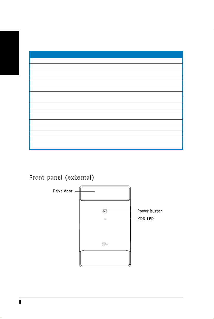
Front panel (external)
Item description
1. ASUS T3-P5G965 barebone system with
•
ASUS motherboard
•
250 W PFC power supply unit
•
Gigabit LAN port
•
CPU fan and heatsink assembly
•
1 x 5.25” drive bays
•
2 x 3.5” hard disk drive bay
2. Cables
•
AC power cord
•
ATA cable
•
Serial ATA cable
•
Serial ATA power cable
3. Support CD
4. User guide
5. Optional items
•
Optical drive
(CD-ROM/CD-RW/DVD-ROM/DVD-RW)
•
6 x USB 2.0 ports
•
2 x IEEE 1394a ports
•
S/PDIF IN&OUT port
•
7-in-1 storage card reader
Drive door
Power button
HDD LED
iii
English
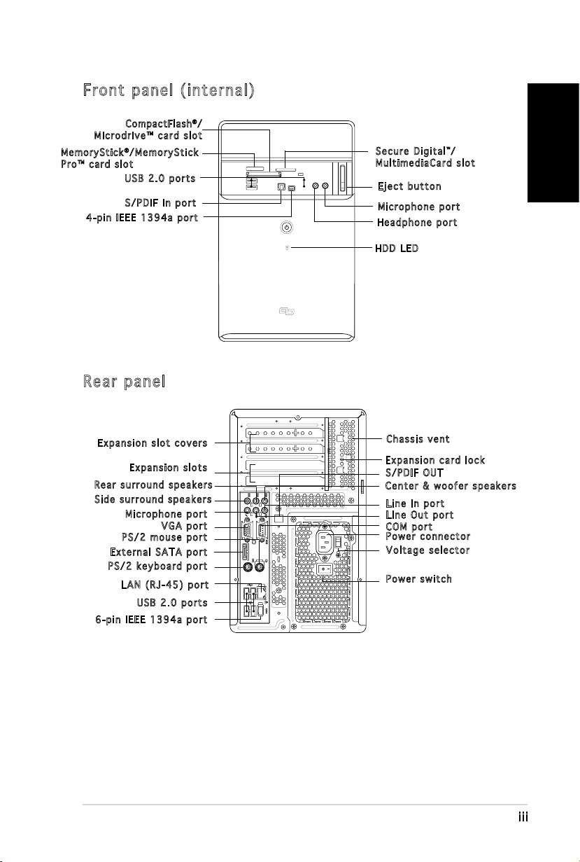
Front panel (internal)
REAR
S P K
LINE
IN
FRONT
MIC IN
SIDE
S P K
C T R
BASS
eSATA
Compa ctF lash®/
Microdrive™ card slot
Me m o r yStick®/MemoryStick
Pro™ card slot
USB 2.0 ports
S/PDIF In port
4-pin IEEE 1394a port
Rear panel
Secure Digital™/
MultimediaCard slot
Eject button
Microphone port
Headphone port
HDD LED
Expansion slot covers
Expansion slots
Rear surround speakers
Side surround speakers
Microphone port
VGA port
PS/2 mouse port
External SATA port
Chassis vent
Expansion card lock
S/PDIF OUT
Center & woofer speakers
Line In port
Line Out port
COM port
Power connector
Voltage selector
PS/2 keyboard port
LAN (RJ-45) port
Power switch
USB 2.0 ports
6-pin IEEE 1394a port
iv
English
Installation
IMPORTANT! Refer to the system user guide for installation details and
other system information.
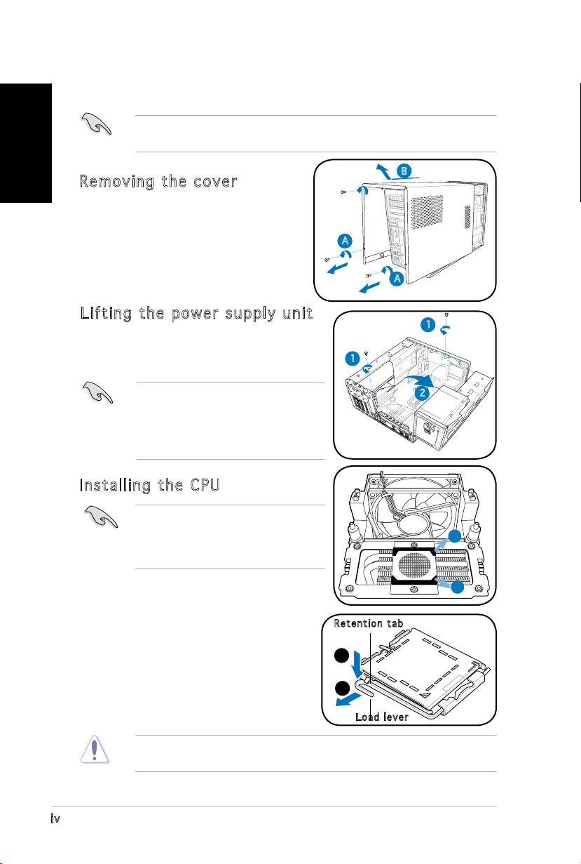
Removing the cover
1. Locate and remove three cover
screws.
2. Pull the cover toward the rear panel
(A), then lift (B).
Lifting the power supply unit
1. Locate and remove the two screws.
2. Lift the PSU in the direction of the
arrow to a 90º angle.
IMPORTANT! When removing the
PSU, make sure to hold or support
it rmly. The unit might accidentally
drop and damage the other system
components.
Installing the CPU
IMPORTANT! Before installing the
CPU, remove the two rubbers (A and
B) attached to the bottom of the
cooler / fan.
B
A
A
1
1
2
A
To install a CPU:
1. Locate the CPU socket on the
motherboard.
2. Press the load lever with your thumb
(A), then move it to the left (B) until
it is released from the retention tab.
To prevent damage to the socket pins, do not remove the PnP cap
unless you are installing a CPU.
B
Retention tab
A
B
Load lever
v
English
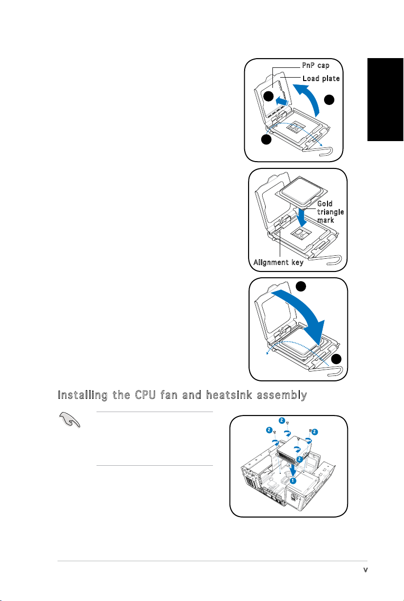
3. Lift the load lever in the direction of the
arrow to a 135º angle.
4. Lift the load plate with your thumb and
forenger to a 100º angle (4A), then
push the PnP cap from the load plate
window to remove (4B).
5. Position the CPU over the socket, making
sure that the gold triangle is on the
bottom-left corner of the socket. Fit the
socket alignment key into the CPU notch.
4B
3
Alignment key
PnP cap
Load plate
4A
Gold
triangle
mark
6. Close the load plate (A), then push the
A
load lever (B) until it snaps into the
retention tab.
Installing the CPU fan and heatsink assembly
Make sure to turn off your
computer and unplug the cable
from the power source before
installing the CPU fan and the
heatsink assembly.
1. Position the CPU fan and the heatsink
assembly on top of the installed CPU.
2. Drive in four screws into the CPU fan
screw holes.
3. Connect the CPU fan cable to the
connector on the motherboard.
2
2
2
1
B
2
vi
English
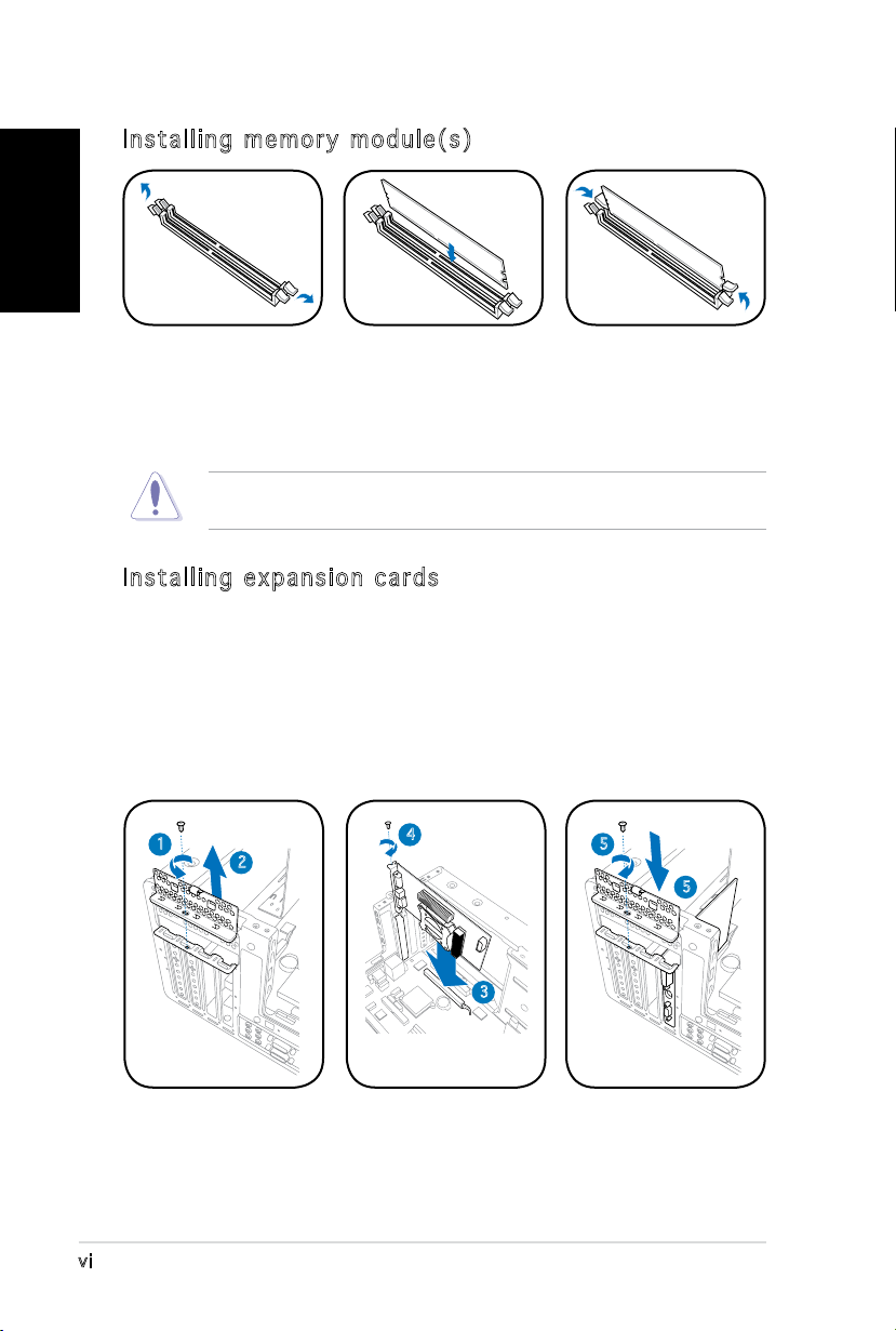
Installing memory module(s)
1. Press the
retaining clips of
the DIMM socket
outward.
2. Align a DIMM on
the socket.
3. Insert the DIMM
rmly to the
socket until the
retaining clips snap
back in place.
CAUTION! A DDR DIMM is keyed with a notch so that it ts in only one
direction. Do not force a DIMM into a socket to avoid damaging the DIMM!
Installing expansion cards
1. Locate and remove one metal bracket lock screw.
2. Remove the metal bracket lock.
3. Align the card connector with the slot, then press rmly.
4. Secure the card with one screw.
5. Replace the metal braket lock, then secure it with one screw.
1
2
4
5
5
3
vii
English
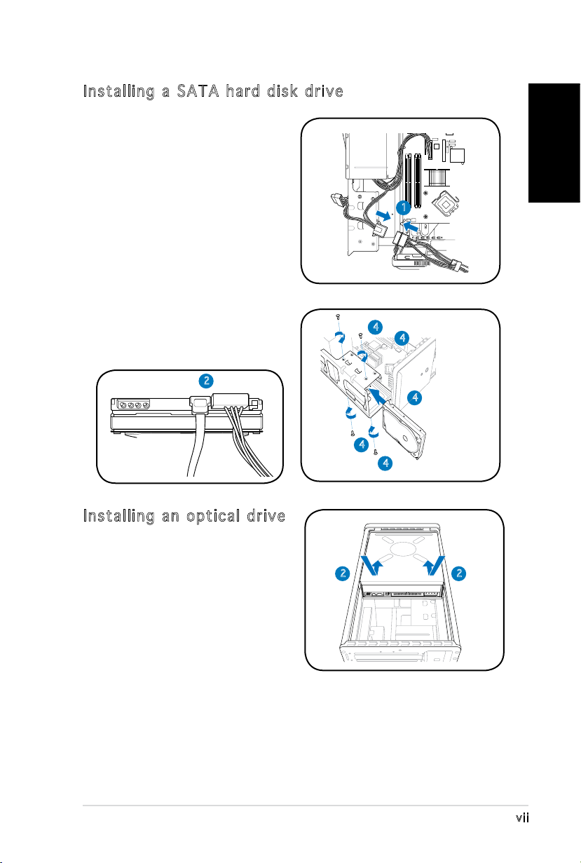
Installing a SATA hard disk drive
1. Connect the SATA power
cable to the plug of the power
supply unit.
2. Connect the SATA signal cable
and the power plugs to the
connectors at the back of the
drive.
3. Locate the HDD tray.
4. Insert a hard disk drive (with
the HDD PCB facing the top of
the chassis) to the tray, then
secure it with four screws.
5. Connect the SATA signal cable
to the SATA connector on the
motherboard, and tighten all the
cables with the plastic coils.
2
1
4
4
4
4
4
Installing an optical drive
1. Place the chassis upright.
2. Insert the optical drive to the
upper 5.25 in drive bay, then
carefully push the drive until
its screw holes align with the
holes on the bay.
22
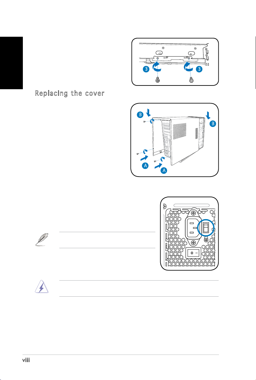
3. Secure the optical drive with
English
4. Connect the IDE and the power
Replacing the cover
1. Fit the cover tabs with the
2. Secure the cover with three
four screws on both sides of
the bay.
plugs to the connectors at the
back of the drive.
chassis rail and the front panel
tabs (A), then lower the rear
edge of the cover as shown
(B).
screws.
3 3
B
B
A
Selecting the voltage
The PSU has a 115 V/230 V voltage selector
switch located beside the power connector. Use
this switch to select the appropriate system
input voltage according to the voltage supply in
your area.
NOTE. The voltage selector is set to
230 V by default.
If the voltage supply in your area is 100-127 V,
set the switch to 115 V. If the voltage supply in
your area is 200-240 V, set the switch to 230 V.
WARNING! Setting the switch to 115 V in a 230 V environment will
seriously damage the system!
A
viii
®
T3-P5G965
ASUS PC (Système barebone)
Guide d’installation rapide
Français
Copyright © 2006 ASUS T e K C O M P U T E R I N C . T o u s d r o i t s r é s e r v é s .
ii
Français
Contenu du carton
Vériez que les éléments suivants accompagnent bien votre T3-P5G965.
Contactez votre revendeur immédiatement si l’un d’entre eux était
manquant ou endommagé.
Description des éléments
1. Système barebone ASUS T3-P5G965 avec
•
Carte mère ASUS
•
Alimentation 250 W PFC
•
Port Gigabit LAN
•
Assemblage dissipateur/ventilateur pour CPU • Lecteur de cartes 7-en-1
•
1 x baie 5.25”
•
2 x baies pour disque dur 3.5”
2. Câbles
•
Câble d’alimentation
•
Câble ATA
•
Câble Serial ATA
•
Câble d’alimentation Serial ATA
3. CD de support
4. Manuel
5. Eléments optionnels
•
Lecteur optique
(CD-ROM/CD-RW/DVD-ROM/DVD-RW)
•
6 x ports USB 2.0
•
2 x ports IEEE 1394a
•
Port S/PDIF IN&OUT
Caractéristiques
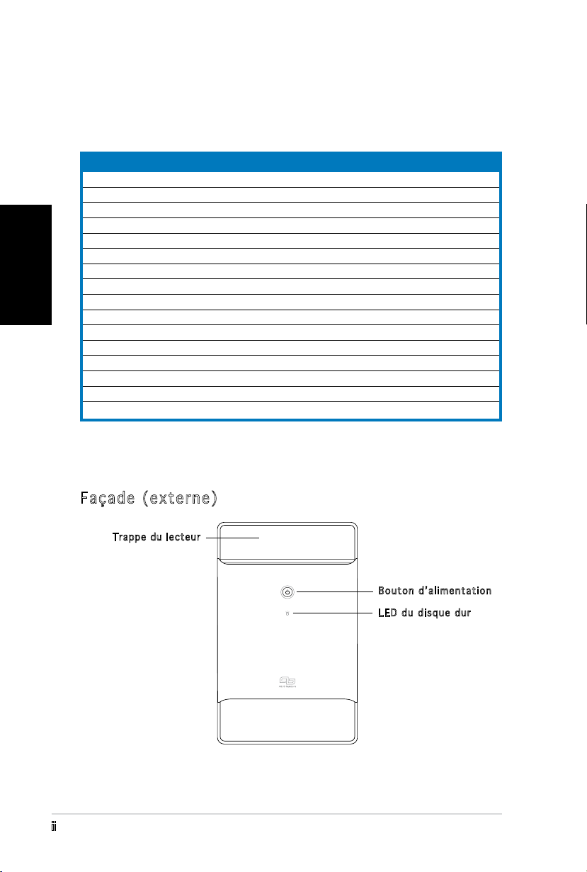
Façade (externe)
Tr appe du le cteur
Bouton d’alimentation
LED du disque dur
iii
Français
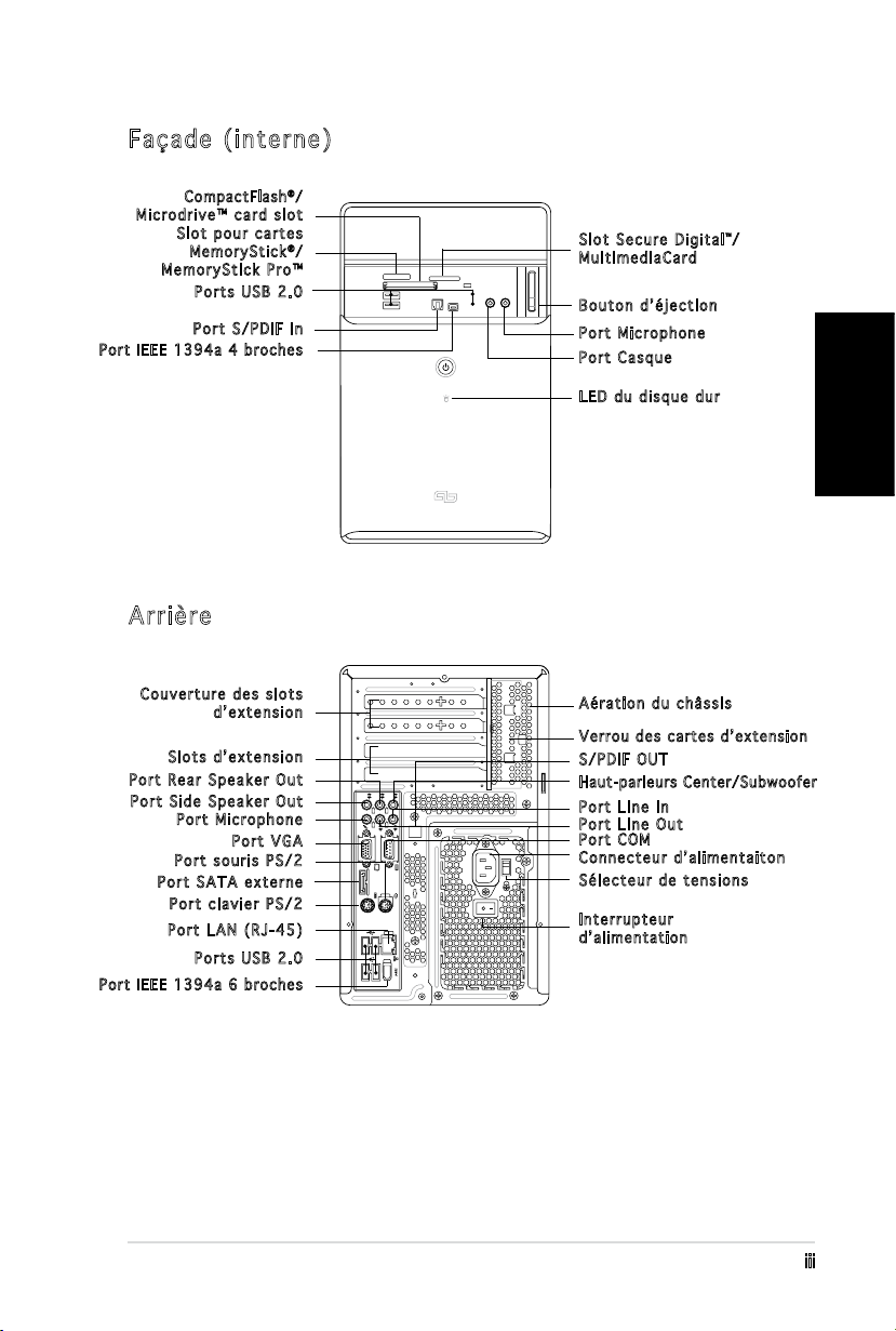
Façade (interne)
REAR
S P K
LINE
IN
FRONT
MIC IN
SIDE
S P K
C T R
BASS
eSATA
Compa ctF lash®/
Microdrive™ card slot
Slot pour cartes
Me m o r yStick®/
MemoryStick Pro™
Ports USB 2.0
Port S/PDIF In
Po rt IE EE 13 94a 4 bro c hes
Arrière
Slot Secure Digital™/
MultimediaCard
Bouton d’éjection
Port Microphone
Port Casque
LED du disque dur
Couverture des slots
d’extension
Aération du châssis
Ve rrou des c artes d’ex tensi on
Slots d’extension
Port Rear Speaker Out
Port Side Speaker Out
Port Microphone
Port VGA
Port souris PS/2
Port SATA externe
Port clavier PS/2
Port LAN (RJ-45)
S/PDIF OUT
Haut-parleurs Center/Subwoofer
Port Line In
Port Line Out
Port COM
Connecteur d’alimentaiton
Sélecteur de tensions
Interrupteur
d’ a limen t a tion
Ports USB 2.0
Po rt IE EE 13 94a 6 bro c hes
iv
Français
Installation
IMPORTANT ! reportez-vous au manuel pour plus de détails d’installation
et autres informations système.
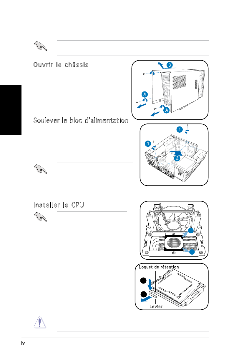
Ouvrir le châssis
1. Localisez et dévissez les trois
vis de châssis.
2. Tirez vers l’arrière (A), puis
levez (B).
Soulever le bloc d’alimentation
1. Localisez et retirez les deux vis
du bloc d’alimentation.
2. Soulevez l’unité d’alimentation
dans la direction de la èche
dans un angle de 90º.
IMPORTANT ! lorsque vous enlevez
l’alimentation assurez-vous de bien
la tenir car elle pourrait tomber et
endommager les autres composants
du système.
Installer le CPU
IMPORTANT ! Avant d’installer le
CPU, retirez les deux protections
en caoutchouc(A and B) situées
au dessous du refroidisseur/
ventilateur.
B
A
A
1
1
2
A
Pour installer un CPU:
1. Localisez le socket du CPU sur la
carte mère.
2. Pressez le levier avec votre pouce
(A) et glissez-le vers la gauche (B)
jusqu’à ce qu’il soit libéré du loquet
de rétention.
Pour éviter d’endommager les broches du socket, ne retirez pas le cache
PnP sauf pour installer le CPU.
B
Lo q u e t d e rétent i o n
A
B
Levier
v
Français
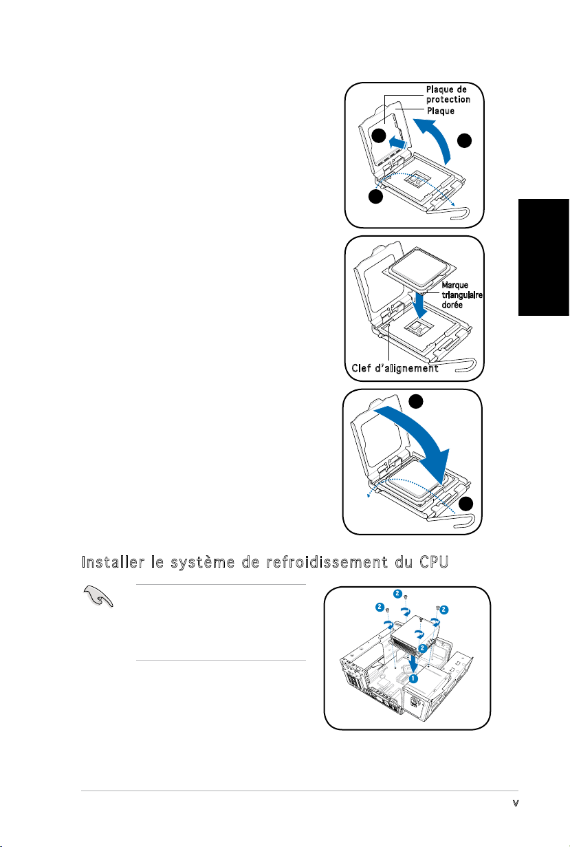
3. Levez le levier dans la direction de la
èche à un angle de 135º.
4. Levez la plaque avec votre pouce à
un angle de 100°(4A), puis poussez
le couvercle PnP de la plaque pour
l’enlever (4B).
5. Placez le CPU au dessus du socket,
en vous assurant que le triangle doré
soit dans le coin inférieur gauche du
socket. La clef d’alignement du socket
doit correspondre avec l’encoche du
CPU.
Pl a q u e de
pr o t e ctio n
Pl a q u e
4B
3
Clef d’alignement
4A
Marque
triangulaire
dorée
6. Refermez la plaque (A), puis poussez le
levier (B) jusqu’à ce qu’il soit accroché
A
par le loquet de rétention.
Installer le système de refroidissement du CPU
Assurez-vous d’éteindre
l’ordinateur et de débrancher
le câble d’alimentation avant
d’installer l’ensemble dissipateur/
ventilateur.
1. Positionnez l’ensemble dissipateur/
ventilateur sur le CPU installé.
2. Vissez quatre vis dans les pas de vis
du ventilateur.
3. Connectez le câble du ventilateur au connecteur de la carte mère.
2
2
2
2
1
B
vi
Français
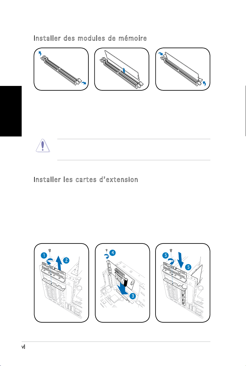
Installer des modules de mémoire
1. Pressez les clips
de rétention des
sockets DIMM vers
l’extérieur.
2. Alignez un module
sur le socket.
3. Insérez le module
DIMM dans le
socket jusqu’à
ce que lec clips
reviennent en
place.
ATTENTION ! Un module DIMM DDR est verrouillé par une encoche
de sorte qu’il ne puisse entrer que dans un seul sens. Ne forcez pas
inutilement sur un module pour ne pas l’endommager.
Installer les cartes d’extension
1. Repérez et retirez une des vis de blocage de l’attache métallique.
2. Retirez la sécurité de l’attache métallique.
3. Alignez le connecteur de la carte sur le slot, puis insérez-le
fermement.
4. Fixez la carte à l’aide d’une vis.
5. Repositionnez la sécurité, puis xez-la à l’aide d’une vis.
1
2
4
5
5
3
vii
Français
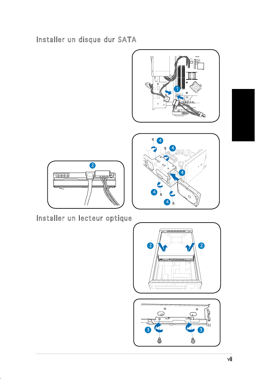
Installer un disque dur SATA
1. Connectez le câble
d’alimentation SATA à la prise
du bloc d’alimentation.
2. Connectez le câble SATA ainsi
que les prises d’alimentation
aux connecteurs situés à
l’arrière du disque.
3. Repérez la baie pour disque dur.
4. Insérez un disque dur (les circuits
imprimés orientés vers le haut du
châssis) dans la baie, puis xezle à l’aide de quatre vis.
5. Reliez le câble SATA au
connecteur SATA de la carte
mère. Regroupez les câbles à
l’aide des anneaux en plastique.
2
1
4
4
4
4
4
Installer un lecteur optique
1. Mettez le châssis en position
verticale.
2. Insérez le lecteur optique
dans la baie 5.25” supérieure,
puis faites le coulisser avec
précaution, jusqu’à ce que ses
pas de vis s’alignent avec ceux
de la baie.
3. Fixez-le de part et d’autre de
la baie à l’aide de quatre vis.
4. Connectez les câbles IDE, et
d’alimentation aux connecteurs
situés à l’arrière du lecteur.
2
3 3
2
Français
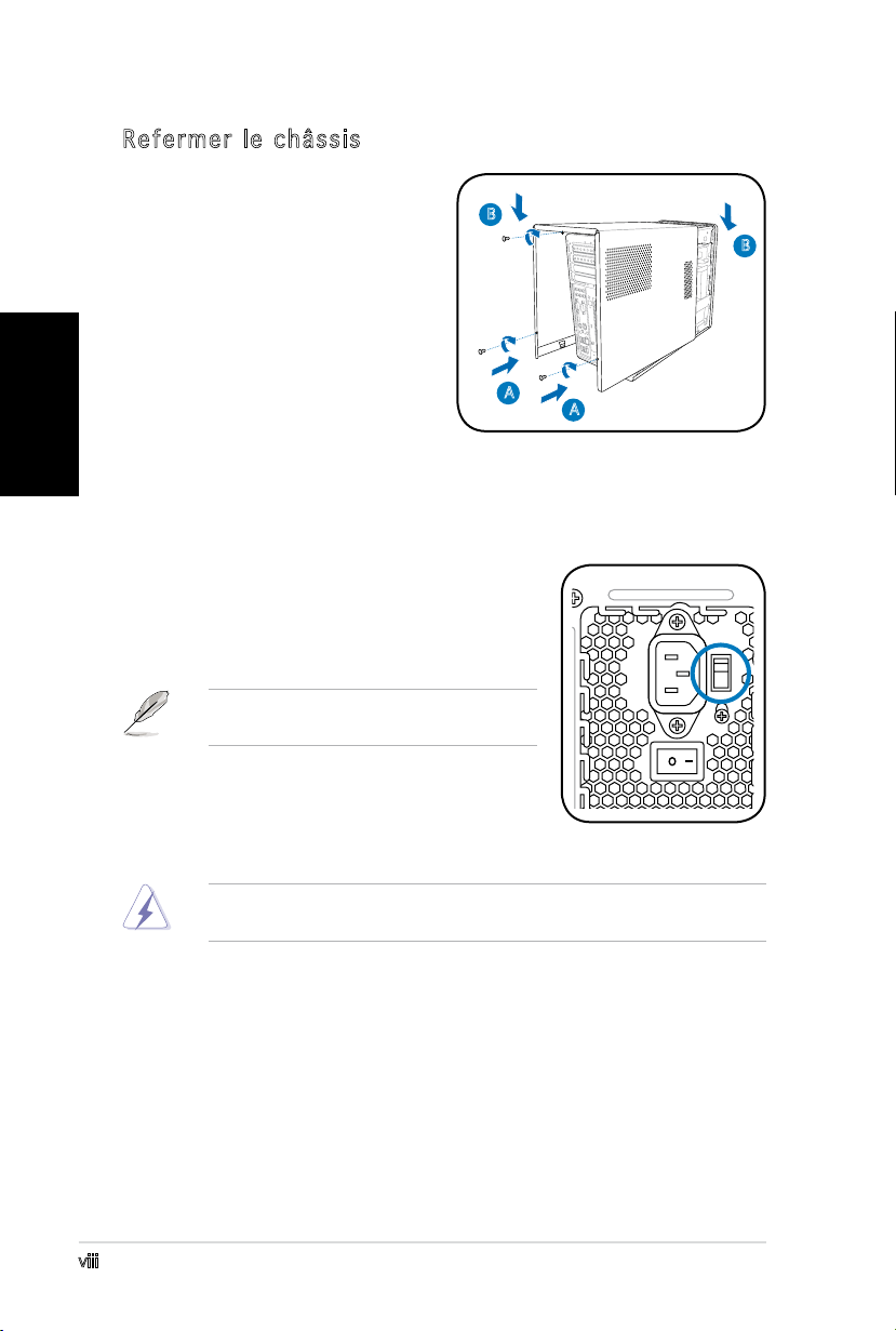
Refermer le châssis
1. Alignez les onglets du capot
avec le rail du châssis et les
onglets de la façade (A), puis
B
baissez le bord arrière comme
indiqué (B).
2. Fixez le capot avec trois vis.
A
Choisir le voltage
L’alimentation est équipée d’un sélecteur de
tension 115 V/230 V situé près du connecteur
d’alimentation. Utilisez cet interrupteur pour
choisir la tension d’entrée appropriée à votre
région.
NOTE. le sélecteur de tension est placé
sur 230 V par défaut.
B
A
Si la tension dans votre région est de 100-127
V, passez l’interrupteur sur 115 V. Si la tension
dans votre région est de 200-240 V, passez
l’interrupteur sur 230 V.
ATTENTION ! Paser l’interrupteur sur 115 V dans une région à 230 V
endommagera gravement le système !
viii

®
T3-P5G965
ASUS PC (Desktop Barebone)
Schnellinstallationsanleitung
Deutsch
Copyright © 2006 ASUS T e K C O M P U T E R I N C . A l l e R e c h t e v o r b e h a l t e n .
ii
Deutsch
Systempaketinhalt
Die folgenden Artikel gehören zum Lieferumfang des T3-P5G965-Systems.
Wenden Sie sich bitte an Ihren Händler, wenn irgendein Artikel beschädigt
ist oder fehlt.
Artikelbeschreibung
1. ASUS T3-P5G965 Barebone-System mit
•
ASUS-Motherboard
•
250 W PFC Netzteil
•
Gigabit LAN-Anschluss
•
CPU-Lüfter-Kühlkörper-Einheit
•
1 x 5,25” Laufwerkfächer
•
2 x 3,5” Festplattenfach
2. Kabel
•
Netzkabel
•
ATA-Kabel
•
Serial ATA-Kabel
•
Serial ATA-Stromkabel
3. Support-CD
4. Benutzerhandbuch
5. Optionale Artikel
•
Optisches Laufwerk
(CD-ROM/CD-RW/DVD-ROM/DVD-RW)
•
6 x USB 2.0-Anschlüsse
•
2 x IEEE 1394a-Anschlüsse
•
S/PDIF IN&OUT-Anschluss
•
7-in-1 Speicherkartenleser
Komponenten
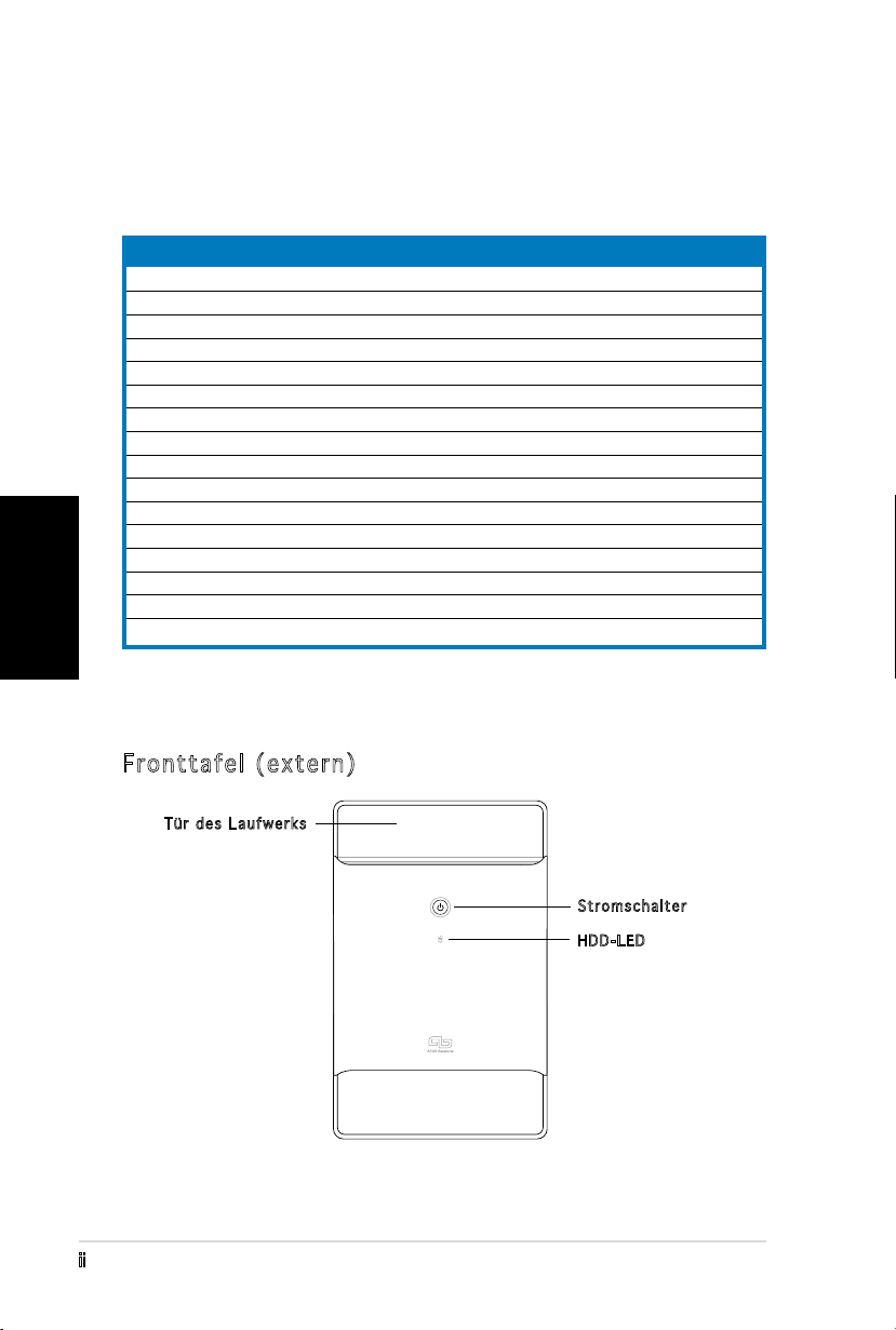
Fronttafel (extern)
Tür des Laufwerks
Stromschalter
HDD-LED
iii
Deutsch
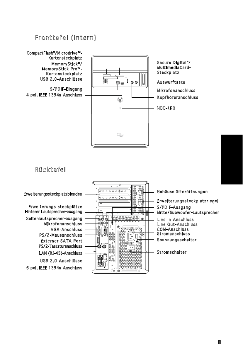
Fronttafel (intern)
REAR
S P K
LINE
IN
FRONT
MIC IN
SIDE
S P K
C T R
BASS
eSATA
CompactFlash®/Microdrive™-
Kartensteckplatz
Me m o r yStick®/
MemoryStick Pro™-
Kartensteckplatz
USB 2.0-Anschlüsse
S/PDIF-Eingang
4-pol. IEEE 1394a-Anschluss
Rücktafel
Erweiterungssteckplatzblenden
Erweiterungs-steckplätze
Hinterer Lautsprecher-ausgang
Seite nla utsprec her -ausgan g
Mikrofonanschluss
VGA-Anschluss
PS/2-Mausanschluss
Externer SATA-Port
PS/2-Tastaturanschluss
LAN (RJ-45)-Anschluss
USB 2.0-Anschlüsse
6-pol. IEEE 1394a-Anschluss
Secure Digital™/
MultimediaCard-
Steckplatz
Auswurftaste
Mikrofonanschluss
Kopfhöreranschluss
HDD-LED
Gehäuselüfteröffnungen
Erweiterungssteckplatzriegel
S/PDIF-Ausgang
Mitte /Su bwoofer -La utsprec her
Line In-Anschluss
Line Out-Anschluss
COM-Anschluss
Stromanschluss
Spannungsschalter
Stroms c h a l t e r
iv
Deutsch
Installation
WICHTIG! Sehen Sie bitte im Systembenutzerhandbuch für
Installationsdetails und sonstige Informationen nach.
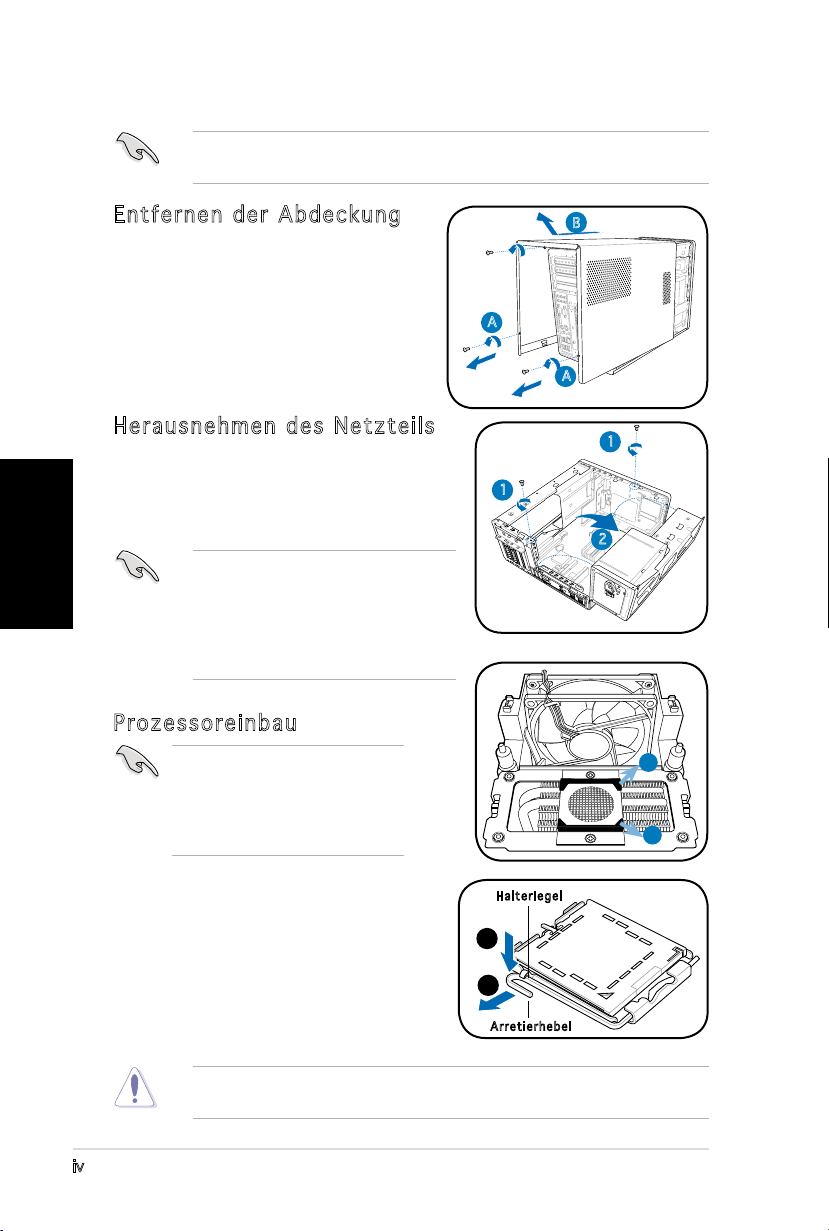
Entfernen der Abdeckung
1. Suchen und entfernen Sie die
drei Abdeckungsschrauben.
2. Ziehen Sie die Abdeckung in
Richtung der Rücktafel (A) und
heben sie dann hoch (B).
Herausnehmen des Netzteils
1. Suchen und entfernen Sie die zwei
Schrauben des Netzteils.
2. Heben Sie die PSU in Pfeilrichtung um
90º an.
WICHTIG! Achten Sie beim Entfernen
des Netzteils darauf, dass Sie
das Netzteil gut festhalten. Das
Netzteil kann aus Versehen
herunterfallen und die anderen
Systemkomponenten beschädigen.
Prozessoreinbau
WICHTIG! Entfernen Sie vor
dem Prozessoreinbau die zwei
Gummistützen (A und B) an der
Unterseite des Kühlkörpers/
Lüfters.
B
A
A
1
1
2
A
B
Installieren des Prozessors:
1. Lokalisieren Sie den Prozessorsockel
auf dem Motherboard.
2. Drücken Sie den Arretierhebel mit
Ihrem Daumen (A) und schieben
ihn nach links (B), bis er von dem
Halteriegel losgelassen wird.
Um eine Beschädigung der Sockel-Pins zu vermeiden, entfernen Sie die
PnP-Abdeckung nicht, bevor Sie den Prozessor installieren.
Ha l t e rieg e l
A
B
Ar r e t ierh e b e l
v
Deutsch
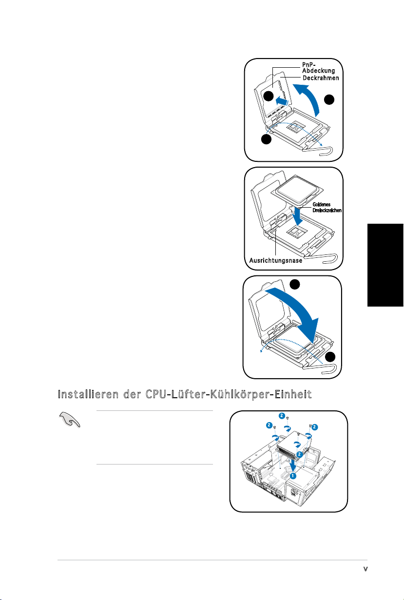
3. Ziehen Sie den Arretierhebel in die
Pfeilrichtung bis zu einem Winkel von
135º hoch.
4. Ziehe Sie den Deckrahmen mit Ihrem
Daumen und Zeigenger bis zu einem
Winkel von 100º hoch (4A) und drücken
Sie dann die PnP-Abdeckung durch die
Aussparung des Deckrahmens, um sie
zu entfernen (4B).
5. Legen Sie die CPU auf den Sockel.
Richten Sie dabei das goldene Dreieck
auf die untere linke Ecke des Sockels
aus. Die Sockelausrichtungsnase muss
in die CPU-Kerbe einpassen.
4B
3
Au s r i chtu n g s nase
Pn P Ab d e c kung
De c k r ahme n
4A
Goldenes
Dreieckzeichen
6. Machen Sie den Deckrahmen (A)
zu. Drücken Sie anschließend den
A
Arretierhebel (B), bis er unter dem
Halteriegel einrastet.
Installieren der CPU-Lüfter-Kühlkörper-Einheit
Schalten Sie unbedingt Ihren
Computer aus und trennen das
Kabel von der Stromquelle, bevor
Sie die CPU-Lüfter-KühlkörperEinheit installieren.
1. Legen Sie die CPU-Lüfter-KühlkörperEinheit auf die installierte CPU.
2. Drehen Sie vier Schrauben in die CPULüfterschraubenlöcher ein.
3. Verbinden Sie das CPU-Lüfterkabel mit dem Lüfteranschluss am
Motherboard.
2
2
2
2
1
B
vi
Deutsch
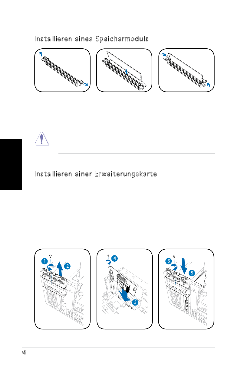
Installieren eines Speichermoduls
1. Drücken Sie die
Haltebügel eines
DIMM-Steckplatzes
nach außen.
2. Richten Sie ein
DIMM auf den
Steckplatz aus.
3. Stecken Sie das
DIMM fest in den
Steckplatz ein,
bis die Haltebügel
einrasten.
VORSICHT! Ein DDR DIMM hat eine Kerbe, so dass es nur in eine Richtung
passt. Stecken Sie ein DIMM nicht mit übermäßiger Kraft in einen
Steckplatz ein, um Schäden am DIMM zu vermeiden!
Installieren einer Erweiterungskarte
1. Entfernen Sie die Schraube, mit der die Metallklammerhalterung
befestigt ist.
2. Entfernen Sie die Metallklammerhalterung.
3. Stecken Sie die Karte in den Steckplatz ein und drücken dann fest
nach unten, bis sie richtig sitzt.
4. Sichern Sie die Karte mit einer Schraube.
5. Setzen Sie die Metallklammerhalterung wieder ein und sichern Sie sie
mit einer Schraube.
1
2
4
5
5
3
vii
Deutsch
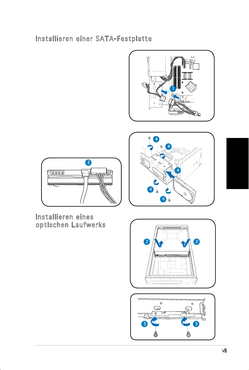
Installieren einer SATA-Festplatte
1. Verbinden Sie das SATA-Stromkabel
mit dem Netzteilstecker.
2. Verbinden Sie das SATASignalkabel und die Stromstecker
mit den Anschlüssen an der
Rückseite des Laufwerks.
3. Suchen Sie den HDD-Schacht.
4. Schieben Sie die Festplatte (die
HDD PCB zur Gehäuse-oberseite
zeigend) in den Schacht und sichern
Sie es mit den vier Schrauben.
5. Verbinden Sie das SATASignalkabel mit dem SATAAnschluss am Motherboard und
befestigen Sie alle Kabel mit den
Plastikschlaufen.
2
1
4
4
4
4
4
Installieren eines
optischen Laufwerks
1. Stellen Sie das Gehäuse
aufrecht hin.
2. Stecken Sie das optische
Laufwerk in den oberen
5.25-Zoll-Schacht und
schieben Sie vorsichtig, bis
die Schraubenlöcher mit
den Löchern am Schacht
übereinstimmen.
3. Sichern Sie das Laufwerk mit
jeweils 2 Schrauben auf jeder
Seite des Schachtes.
4. Verbinden Sie die Stecker
für IDE und Stromversorgung
mit den Anschlüssen an der
Rückseite des Laufwerkes.
2
3 3
2
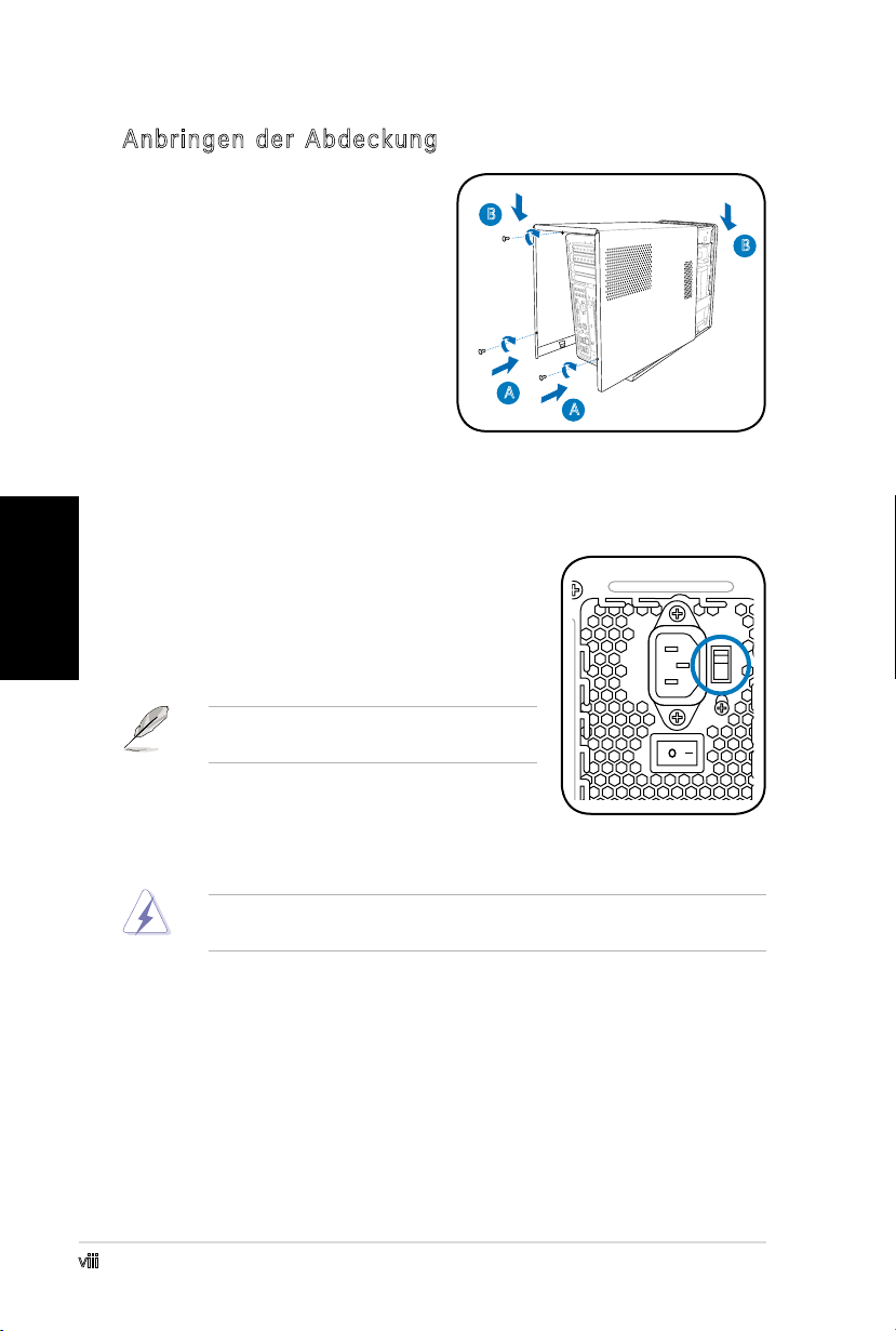
Anbringen der Abdeckung
1. Passen Sie die Zähne der
Abdeckung in die Nut am
Gehäuse und die Haken an
der Fronttafeleinheit ein (A).
Lassen Sie dann die hintere
Kante der Abdeckung wie
dargestellt runter (B).
2. Befestigen Sie die Abdeckung
mit drei Schrauben.
B
B
A
A
Deutsch
Auswählen der Netzspannung
Das Netzteil ist mit einem 115V/230V-
Spannungsschalter neben dem Stromanschluss
ausgestattet. Verwenden Sie diesen Schalter,
um die passende Systemeingangsspannung,
entsprechend Ihrem Stromversorgungssystem in
Ihrer Region, auszuwählen.
HINWEIS. Der Spannungsschalter wurde im
Werk auf 230V eingestellt.
Stellen Sie den Schalter auf 115V, wenn die
Stromversorgung in Ihrer Region 100V bis 127V
ist. Stellen Sie den Schalter auf 230V, wenn die
Stromversorgung in Ihrer Region 200V bis 240V ist.
WARNUNG! Das System wird schwer beschädigt, wenn der Schalter auf
115V eingestellt ist, aber eine Netzspannung von 230V verwendet wird!
viii
 Loading...