

Page 1
T2-PH2
Barebone System
MODE
Page 2
ii
Copyright © 2006 ASUSTeK COMPUTER INC. All Rights Reserved.
No part of this manual, including the products and software described in it, may be reproduced,
transmitted, transcribed, stored in a retrieval system, or translated into any language in any form
or by any means, except documentation kept by the purchaser for backup purposes, without the
express written permission of ASUSTeK COMPUTER INC. (“ASUS”).
Product warranty or service will not be extended if: (1) the product is repaired, modified or
altered, unless such repair, modification of alteration is authorized in writing by ASUS; or (2) the
serial number of the product is defaced or missing.
ASUS PROVIDES THIS MANUAL “AS IS” WITHOUT WARRANTY OF ANY KIND, EITHER EXPRESS
OR IMPLIED, INCLUDING BUT NOT LIMITED TO THE IMPLIED WARRANTIES OR CONDITIONS OF
MERCHANTABILITY OR FITNESS FOR A PARTICULAR PURPOSE. IN NO EVENT SHALL ASUS,
ITS DIRECTORS, OFFICERS, EMPLOYEES OR AGENTS BE LIABLE FOR ANY INDIRECT, SPECIAL,
INCIDENTAL, OR CONSEQUENTIAL DAMAGES (INCLUDING DAMAGES FOR LOSS OF PROFITS, LOSS
OF BUSINESS, LOSS OF USE OR DATA, INTERRUPTION OF BUSINESS AND THE LIKE), EVEN IF ASUS
HAS BEEN ADVISED OF THE POSSIBILITY OF SUCH DAMAGES ARISING FROM ANY DEFECT OR
ERROR IN THIS MANUAL OR PRODUCT.
SPECIFICATIONS AND INFORMATION CONTAINED IN THIS MANUAL ARE FURNISHED FOR
INFORMATIONAL USE ONLY, AND ARE SUBJECT TO CHANGE AT ANY TIME WITHOUT NOTICE, AND
SHOULD NOT BE CONSTRUED AS A COMMITMENT BY ASUS. ASUS ASSUMES NO RESPONSIBILITY
OR LIABILITY FOR ANY ERRORS OR INACCURACIES THAT MAY APPEAR IN THIS MANUAL,
INCLUDING THE PRODUCTS AND SOFTWARE DESCRIBED IN IT.
Products and corporate names appearing in this manual may or may not be registered
trademarks or copyrights of their respective companies, and are used only for identification or
explanation and to the ownersʼ benefit, without intent to infringe.
E242 9
Firs t E diti o n V1
Marc h 2 006
Page 3
iii
Table of contents
Notices ................................................................................................ vi
Safety information ............................................................................. vii
About this guide .................................................................................viii
System package contents .................................................................... x
Cha p te r 1 : S y ste m I n tro d uc t ion
1.1 Welcome! .............................................................................. 1-2
1.2 Front panel (external) ........................................................... 1-2
1.3 Front panel (internal) ............................................................ 1-5
1.4 Rear panel ............................................................................. 1-7
1.5 Internal components ............................................................. 1-9
1.6 LED panel ............................................................................ 1-10
Cha p te r 2 : Bas i c I nst a ll a tio n
2.1 Preparation ........................................................................... 2-2
2.2 Before you proceed .............................................................. 2-2
2.3 Removing the cover .............................................................. 2-3
2.4 Removing the power supply .................................................. 2-4
2.5 Installing a CPU ..................................................................... 2-5
2.5.1 Removing the CPU fan and heatsink assembly ....... 2-5
2.5.2 CPU installation ....................................................... 2-6
2.5.3 Reinstalling the CPU fan and heatsink assembly ..... 2-9
2.6 Installing a DIMM ................................................................. 2-10
2.6.1 Memory configurations .........................................2-10
2.6.2 DIMM installation ................................................... 2-13
2.7 Installing an expansion card ................................................ 2-14
2.7.1 Expansion slots ..................................................... 2-14
2.7.2 Expansion card installation .................................... 2-15
2.8 Installing an optical drive .................................................... 2-17
2.9 Installing a floppy disk drive ............................................... 2-20
2.10 Installing a hard disk drive (HDD) .......................................2-21
2.11 Reinstalling the power supply unit ...................................... 2-24
2.12 Replacing the cover ............................................................ 2-26
Page 4
iv
Table of contents
Cha p te r 3 : Sta r ti n g u p
3.1 Installing an operating system .............................................. 3-2
3.2 Powering up .......................................................................... 3-2
3.3 Support CD information ........................................................ 3-2
3.3.1 Running the support CD .......................................... 3-3
3.3.2 Drivers menu ........................................................... 3-3
3.3.3 Utilities menu .......................................................... 3-4
3.3.4 ASUS contact information ...................................... 3-6
3.3.5 Other information ................................................... 3-6
3.4 Software information ............................................................ 3-7
3.4.1 ASUS Radio Player ................................................... 3-7
3.4.2 ASUS Instant Music ................................................. 3-9
3.5 Audio DJ .............................................................................3-11
3.5.1 Playing an audio CD/DVD ...................................... 3-11
3.5.2 Tuning into an FM radio station ............................ 3-11
3.5.3 Presetting a station .............................................. 3-12
3.5.4 Adjusting the volume ............................................ 3-12
Cha p te r 4 : Mot h er b oar d I n fo
4.1 Introduction .......................................................................... 4-2
4.2 Motherboard layout .............................................................. 4-2
4.3 Jumpers ................................................................................ 4-3
4.4 Connectors ........................................................................... 4-5
Cha p te r 5 : BIO S I n for m at i on
5.1 Managing and updating your BIOS ........................................ 5-2
5.1.1 Creating a bootable floppy disk .............................. 5-2
5.1.2 ASUS EZ Flash utility ............................................... 5-3
5.1.3 AFUDOS utility ........................................................ 5-4
5.1.4 ASUS CrashFree BIOS 2 utility ................................ 5-6
5.1.5 ASUS Update utility ................................................ 5-8
5.2 BIOS setup program ............................................................ 5-11
5.2.1 BIOS menu screen ................................................. 5-12
5.2.2 Menu bar ............................................................... 5-12
5.2.3 Navigation keys ..................................................... 5-12
Page 5

v
Table of contents
5.2.4 Menu items ........................................................... 5-13
5.2.5 Sub-menu items .................................................... 5-13
5.2.6 Configuration fields ............................................... 5-13
5.2.7 Pop-up window ...................................................... 5-13
5.2.8 Scroll bar ............................................................... 5-13
5.2.9 General help .......................................................... 5-13
5.3 Main menu ........................................................................... 5-14
5.3.1 System Time ........................................................ 5-14
5.3.2 System Date ........................................................ 5-14
5.3.3 Legacy Diskette A ...............................................5-14
5.3.4 Primary, Third, and Fourth IDE Master/Slave ........ 5-15
5.3.5 IDE Configuration .................................................. 5-16
5.3.6 System Information .............................................. 5-18
5.4 Advanced menu .................................................................. 5-19
5.4.1 Instant Music Configuration ..................................5-19
5.4.2 LAN Cable Status .................................................. 5-20
5.4.3 USB Configuration ................................................. 5-21
5.4.4 CPU Configuration ................................................. 5-22
5.4.5 Chipset .................................................................. 5-24
5.4.6 Onboard Devices Configuration ............................. 5-26
5.4.7 PCI PnP .................................................................. 5-28
5.5 Power menu ........................................................................ 5-30
5.5.1 Suspend Mode ...................................................... 5-30
5.5.2 ACPI 2.0 Support ................................................. 5-30
5.5.3 ACPI APIC Support ................................................ 5-30
5.5.4 APM Configuration ................................................5-31
5.5.5 Hardware Monitor .................................................. 5-33
5.6 Boot menu .......................................................................... 5-34
5.6.1 Boot Device Priority .............................................. 5-34
5.6.2 Boot Settings Configuration ................................. 5-35
5.6.3 Security ................................................................. 5-36
5.7 Exit menu ............................................................................ 5-38
App e nd i x
Power supply specifications .............................................................A-2
Page 6
vi
Notices
Fed er al Co mm un ica ti on s C om mi ssi on S tat em en t
This device complies with Part 15 of the FCC Rules. Operation is subject to
the following two conditions:
•
This device may not cause harmful interference, and
•
This device must accept any interference received including
interference that may cause undesired operation.
This equipment has been tested and found to comply with the limits for a
Class B digital device, pursuant to Part 15 of the FCC Rules. These limits
are designed to provide reasonable protection against harmful interference
in a residential installation. This equipment generates, uses and can radiate
radio frequency energy and, if not installed and used in accordance with
manufacturerʼs instructions, may cause harmful interference to radio
communications. However, there is no guarantee that interference will
not occur in a particular installation. If this equipment does cause harmful
interference to radio or television reception, which can be determined by
turning the equipment off and on, the user is encouraged to try to correct
the interference by one or more of the following measures:
•
Reorient or relocate the receiving antenna.
•
Increase the separation between the equipment and receiver.
•
Connect the equipment to an outlet on a circuit different from that to
which the receiver is connected.
•
Consult the dealer or an experienced radio/TV technician for help.
Can ad ia n D ep ar tme nt o f C om mu nic at io ns St at eme nt
This digital apparatus does not exceed the Class B limits for radio noise
emissions from digital apparatus set out in the Radio Interference
Regulations of the Canadian Department of Communications.
This class B digital apparatus complies with Canadian ICES-003.
WARNING! The use of shielded cables for connection of the monitor to
the graphics card is required to assure compliance with FCC regulations.
Changes or modifications to this unit not expressly approved by the
party responsible for compliance could void the userʼs authority to
operate this equipment.
Page 7
vii
Safety information
Ele ct ri cal s af ety
•
To prevent electrical shock hazard, disconnect the power cable from
the electrical outlet before relocating the system.
•
When adding or removing devices to or from the system, ensure that
the power cables for the devices are unplugged before the signal cables
are connected.
•
If the power supply is broken, do not try to fix it by yourself. Contact a
qualified service technician or your retailer.
Ope ra ti on sa fe ty
•
Before installing devices into the system, carefully read all the
documentation that came with the package.
•
Before using the product, make sure all cables are correctly connected
and the power cables are not damaged. If you detect any damage,
contact your dealer immediately.
•
To avoid short circuits, keep paper clips, screws, and staples away from
connectors, slots, sockets and circuitry.
•
Avoid dust, humidity, and temperature extremes. Do not place the
product in any area where it may become wet. Place the product on a
stable surface.
•
If you encounter technical problems with the product, contact a
qualified service technician or your retailer.
Lithium-Ion Battery Warning
CAUTION: Danger of explosion if battery is incorrectly replaced.
Replace only with the same or equivalent type recommended by
the manufacturer. Dispose of used batteries according to the
manufacturerʼs instructions.
VORSICHT: Explosionsgetahr bei unsachgemäßen Austausch der
Batterie. Ersatz nur durch denselben oder einem vom Hersteller
empfohlenem ähnljchen Typ. Entsorgung gebrauchter Batterien nach
Angaben des Herstellers.
LASER PRODUCT WARNING
CLA SS 1 LA SE R PRO DU CT
Page 8
viii
About this guide
Aud ie nc e
This guide provides general information and installation instructions about
the ASUS T2-PH2 barebone system. This guide is intended for experienced
users and integrators with hardware knowledge of personal computers.
How t hi s g ui de is o rg ani ze d
This guide contains the following parts:
1. Chap t e r 1: S y s tem i n t rodu c t i on
This chapter gives a general description of the ASUS T2-PH1. The
chapter lists the system features, including introduction on the front
and rear panel, and internal components.
2. Chap t e r 2: B a s ic i n s t alla t i o n
This chapter provides step-by-step instructions on how to install
components in the system.
3. Chap t e r 3: S t a rtin g u p
This chapter helps you power up the system and install drivers and
utilities from the support CD.
4. Chap t e r 4: M o t herb o a r d in f o r mati o n
This chapter gives information about the motherboard that comes
with the system. This chapter includes the motherboard layout,
jumper settings, and connector locations.
5. Chap t e r 5: B I O S in f o r mati o n
This chapter tells how to change system settings through the BIOS
Setup menus and describes the BIOS parameters.
6. Appe n d i x
The Appendix includes the power supply unit specification for this
system.
Page 9
ix
Con ve nt ion s us ed in t his g ui de
WARNING: Information to prevent injury to yourself when trying
to complete a task.
CAUTION: Information to prevent damage to the components
when trying to complete a task.
IMPORTANT: Instructions that you MUST follow to complete a
task.
NOTE: Tips and additional information to aid in completing a
task.
Whe re t o f in d mor e in for ma ti on
Refer to the following sources for additional information and for product
and software updates.
1. ASUS W e bsit e s
The ASUS websites worldwide provide updated information on
ASUS hardware and software products. Refer to the ASUS contact
information.
2. Opti o n a l Do c u m enta t i o n
Your product package may include optional documentation, such as
warranty flyers, that may have been added by your dealer. These
documents are not part of the standard package.
Page 10
x
System package contents
Check your T2-PH2 system package for the following items.
If any of the items is damaged or missing, contact your retailer
immediately.
Ite m d escri p t i on
1. ASUS T2-PH2 barebone system with
• ASUS motherboard
• 250 W Passive PFC power supply unit
• Gigabit LAN port
• CPU fan and heatsink assembly
• 2 x 5.25” drive bays
• 1 x 3.5” floppy disk drive bay
• 1 x 3.5” hard disk drive bay
• 6 x USB 2.0 ports
• 2 x IEEE 1394a ports
• S/PDIF in/out ports
• 7-in-1 storage card reader
• FM radio module and radio antenna
• LED panel
• Audio DJ play buttons
2. Cables
• AC power cable
• Ultra ATA 66 cable
• Serial ATA cable
• Serial ATA power cable
3. Support CD
4. User guide
5. Optional items
• Optical drive
(CD-ROM/CD-RW/DVD-ROM/DVD-RW)
• Floppy disk drive
Page 11
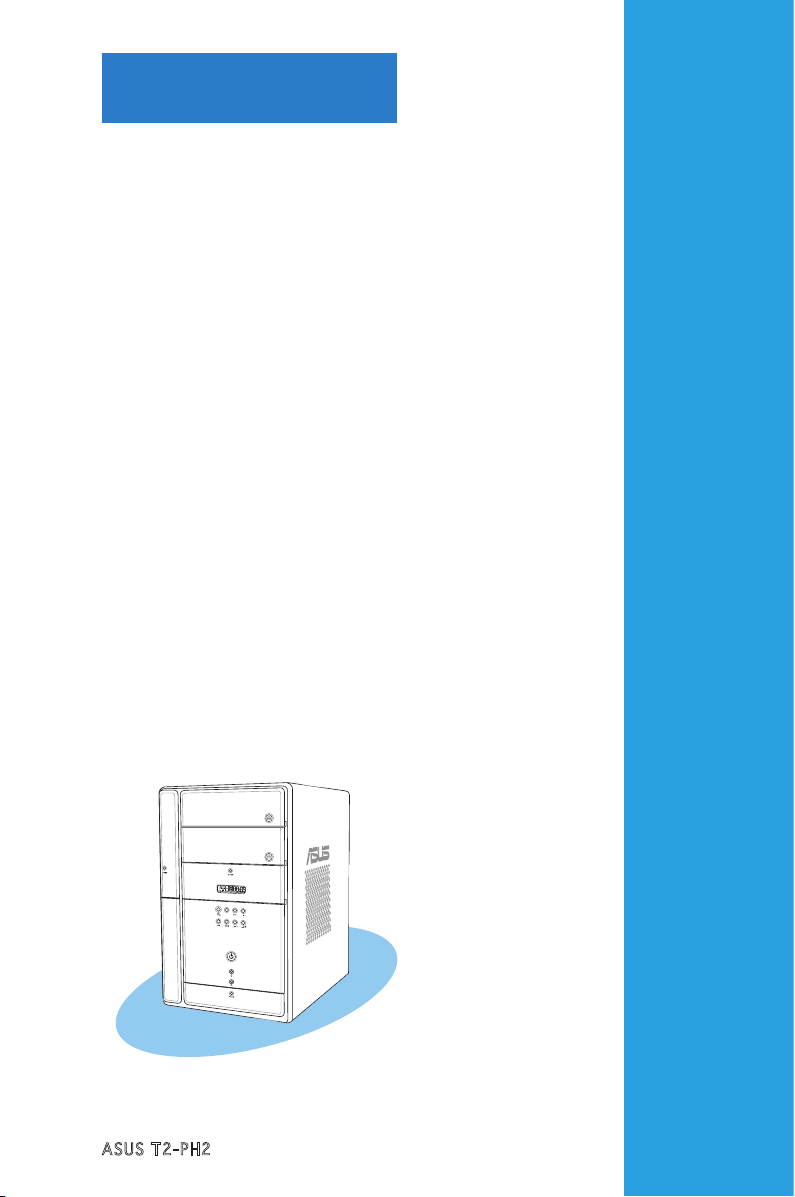
ASUS T2-PH2
MODE
Chapter 1
System introduction
This chapter gives a general
description of the ASUS
T2-PH2. The chapter lists the
system features including
introduction on the front and rear
panel, and internal components.
Page 12
1-2
Chapter 1: System introduction
1.1 Welcome!
Thank you for choosing the ASUS T2-PH2!
The ASUS T2-PH2 is an all-in-one barebone system with a versatile home
entertainment feature.
The system comes in a stylish mini-tower casing, and powered by the ASUS
motherboard that supports the Intel® Pentium® 4 processor in the 775-land
package with 533/800/1066 MHz FSB and up to 2 GB system memory.
With audio functions, extensive connectivity, and Gigabit LAN capability,
the T2-PH2 is designed for the sophisticated.
With these and many more, the T2-PH2 definitely delivers the cutting edge
technology for your computing and multimedia needs!
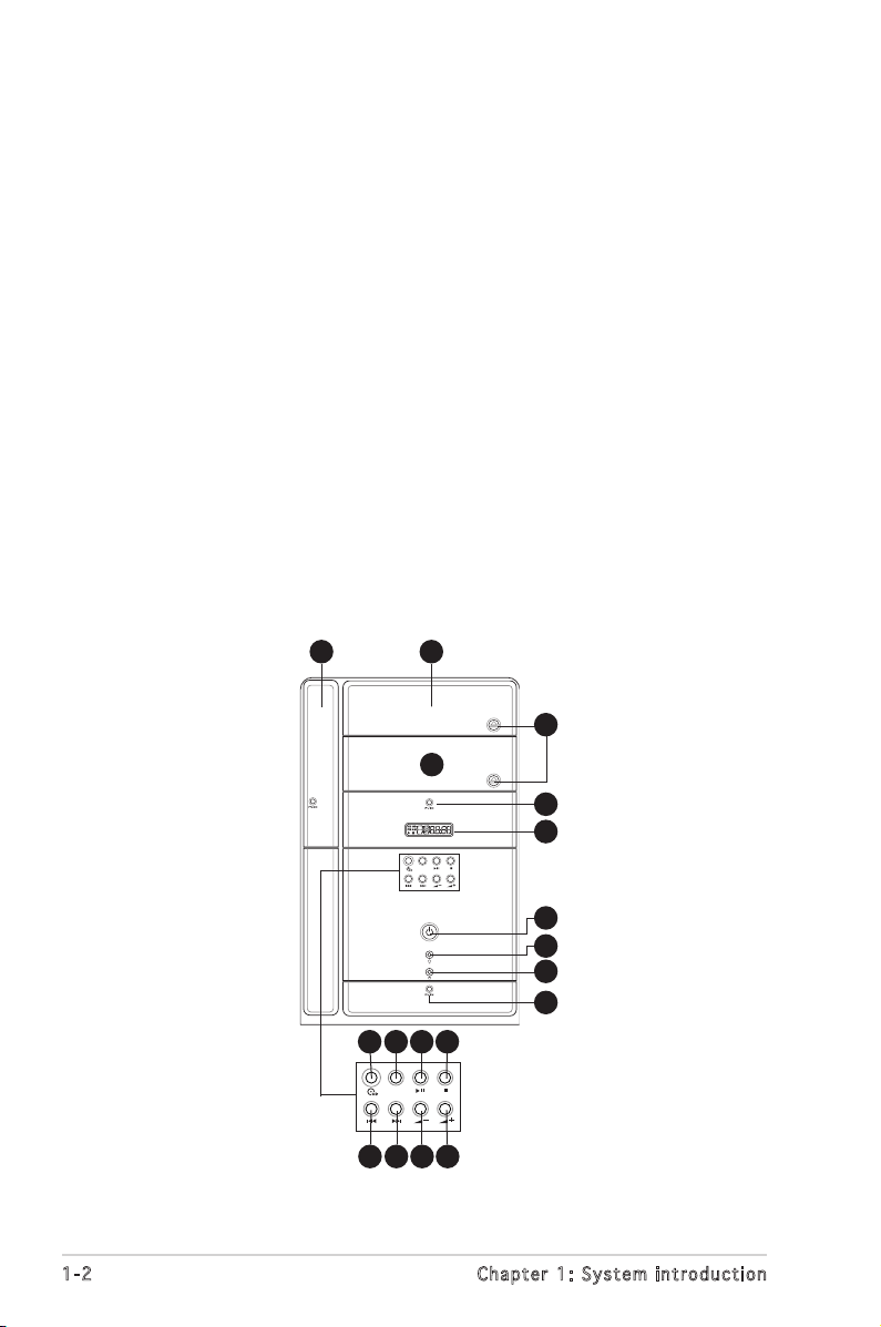
1.2 Front panel (external)
The front panel includes the system and audio control buttons, system
LEDs, and LED panel.
MODE
21
3
4
6
5
7
10
8
9
MODE
11 12 13 14
15 16 17 18
Page 13
1-3
ASUS T2-PH2
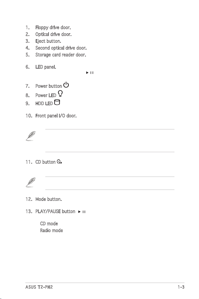
1. Floppy drive door. Open this door to access the floppy disk drive.
2. Optical drive door. This door opens when you eject the loading tray.
3. Eject button. Press this button to eject the optical drive loading tray.
4. Second optical drive door. This door covers a second optical drive bay.
5. Storage card reader door. Open this door to access the 7-in-1 storage
card reader.
6. LED panel. The LED panel displays the audio medium (CD/FM), radio
frequency, player status ( / ), real time clock, track number, and
time. See page 1-10 for details.
7. Power button . Press this button to turn the system on.
8. Power LED . This LED lights up to indicate that the system is ON.
9. HDD LED . This LED lights up when data is being read from or
written to the hard disk drive
10. Front panel I/O door. Open this door to show the front panel input/
output ports.
11. CD button . Press this button to put the Audio DJ function to CD
mode.
12. Mode button. Press this button to switch from CD to FM radio mode
and vice versa.
13. PLAY/PAUSE button ( / ). Press this button to perform various
functions in different modes.
In CD mode, plays or pauses an audio CD track.
In Radio mode, scans the available FM stations when pressed for less
than two seconds or presets a station when pressed for more than
two seconds. Refer to page 3-12 on how to preset a radio station.
In Windows® mode, pressing this button shuts down, restarts, or puts
the system in sleep mode (S3) depending on the OS setting.
The following front panel buttons are activated only when the system
is in Audio DJ mode. The Audio DJ feature allows you to play CD audio
tracks, or tune in to an FM radio station without entering the operating
system. See page 3-11 for details.
Page 14
1-4
Chapter 1: System introduction
14. STOP button . Press this button to stop the audio track being played.
15. PREVIOUS button
. Press this button to perform various functions in
different modes.
In CD mode, selects the previous audio track.
In Radio mode, selects the previous preset station.
16. NEXT button
. Press this button to perform various functions in
different modes.
In CD mode, selects the next audio track.
In Radio mode, selects the next preset station.
17. Volume down button –. Press this button to decrease the system
volume.
18. Volume up button +. Press this button to increase the system
volume.
Page 15
1-5
ASUS T2-PH2
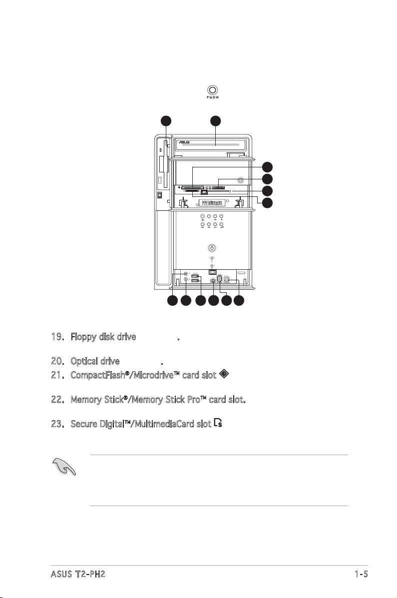
1.3 Front panel (internal)
The optical drive(s), storage card reader slots, and several I/O ports are
located inside the front panel doors.
Open the front panel doors by pressing .
30
19. Floppy disk drive
(optional)
. This drive is for a 1.44 MB, 3.5-inch
floppy disk.
20. Optical drive
(optional)
. This is for optical disks.
21. CompactFlash®/Microdrive™ card slot . This slot is for a
CompactFlash®/Microdrive™ storage card.
22. Memory Stick®/Memory Stick Pro™ card slot. This slot is for a Memory
Stick®/Memory Stick Pro™ storage card.
23. Secure Digital™/MultimediaCard slot . This slot is for a Secure
Digital™/MultimediaCard storage card.
•
You cannot close the storage card reader door if a storage card is
inserted into any of the card slots.
•
Use and format a storage card according to the documentation that
comes with it.
MODE
20
19
21
22
23
24
25
26
27
28
29
28
Page 16
1-6
Chapter 1: System introduction
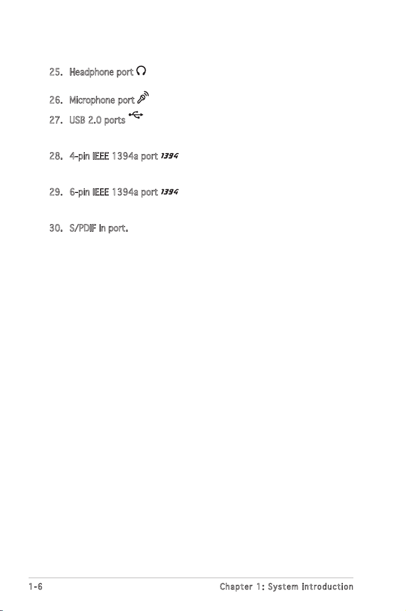
25. Headphone port . This port connects a headphone with a stereo
mini-plug.
26. Microphone port . This Mic (pink) port connects a microphone.
27. USB 2.0 ports
2.0
. These Universal Serial Bus 2.0 (USB 2.0) ports
are available for connecting USB 2.0 devices such as a mouse, printer,
scanner, camera, PDA, and others.
28. 4-pin IEEE 1394a port . This port provides high-speed
connectivity for IEEE 1394a-compliant audio/video devices, storage
peripherals, and other PC devices.
29. 6-pin IEEE 1394a port . This port provides high-speed
connectivity for IEEE 1394a-compliant audio/video devices, storage
peripherals, and other PC devices.
30. S/PDIF In port. This port connects your audio system for 5.1-channel
surround sound and enhanced 3D audio.
Page 17
1-7
ASUS T2-PH2
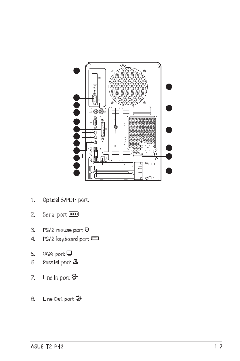
1.4 Rear panel
The system rear panel includes the power connector and several I/O ports
that allow convenient connection of devices.
1. Optical S/PDIF port. This port connects your audio system for
5.1-channel surround sound and enhanced 3D audio.
2. Serial port . This port connects a mouse, modem, or other devices
that conforms with serial specification.
3. PS/2 mouse port . This green 6-pin connector is for a PS/2 mouse.
4. PS/2 keyboard port . This purple 6-pin connector is for a
PS/2 keyboard.
5. VGA port . This port connects a VGA monitor.
6. Parallel port . This 25-pin port connects a printer, scanner, or other
devices.
7. Line In port . This Line In (light blue) port connects a tape player
or other audio sources. In 6-channel mode, the function of this port
becomes Surround output.
8. Line Out port . This Line Out (lime) port connects a headphone or
a speaker. In 4/6-channel mode, the function of this port becomes
Front Speaker Out.
1
3
2
4
5
6
7
8
9
10
11
12
13
14
15
16
17
18
Page 18
1-8
Chapter 1: System introduction
9. Microphone port . This Microphone (pink) port connects a
microphone. In 4/6-channel mode, the function of this port becomes
Low Frequency Enhanced Output/Center.
Aud i o p ort s f u nct i on var i at i on
10. USB 2.0 ports
2.0
. These Universal Serial Bus 2.0 (USB 2.0) ports
are available for connecting USB 2.0 devices such as a mouse, printer,
scanner, camera, PDA, and others.
11. LAN (RJ-45) port . This port allows Gigabit connection to a Local
Area Network (LAN) through a network hub.
12. Expansion slot covers. Remove these covers when installing expansion
cards.
13. Chassis fan vent. This vent is for the fan that provides ventilation
inside the system chassis.
14. Radio antenna port. This port connects a radio antenna.
15. Power supply unit fan vent. This vent is for the PSU fan that provides
ventilation inside the power supply unit.
16. Power connector. This connector is for the power cable and plug.
17. Voltage selector. This switch allows you to adjust the system input
voltage according to the voltage supply in your area. See the “Voltage
selector” section on page 2-25 before adjusting this switch.
18. Expansion card lock. This lock secures installed expansion cards. See
page 2-15 for details.
The functions of the Line Out, Line In, and Microphone ports change
when you select the 6-channel configuration. Refer to the table below
for audio ports function variation.
* L o w F reque n c y Enhan c e d Outpu t
Por t Hea d p h one/2 - C h annel 4 - C hanne l 6-C h a n nel
Light Blue Line In Surround Surround
Lime Line Out Front Speaker Out Front Speaker Out
Pink Mic In Mic In LFE Output*/Center
Page 19
1-9
ASUS T2-PH2
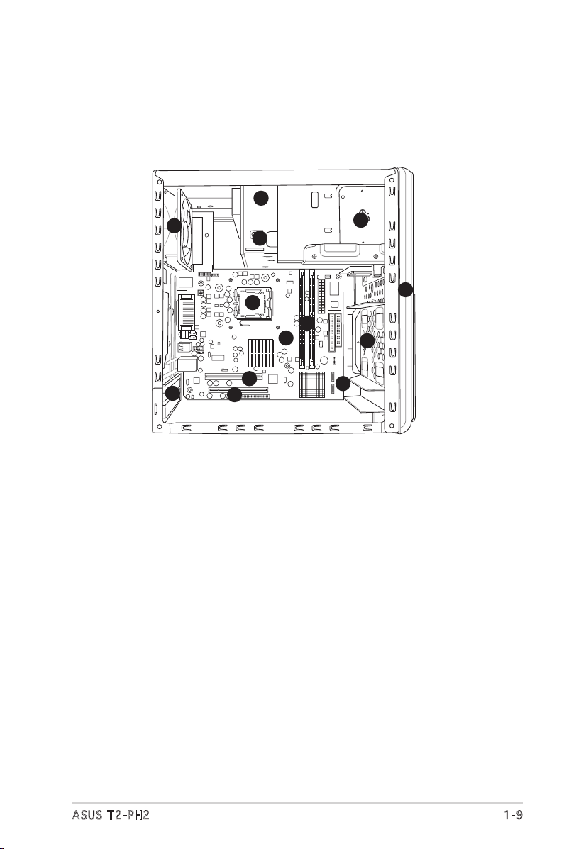
1. Optical drive
(optional)
2. 5.25-inch empty optical drive bay
3. Floppy disk drive
(optional)
4. Front panel cover
5. Hard disk drive metal tray
6. Chassis fan
7. ASUS motherboard
8. DIMM sockets
9. LGA775 socket with PnP cap
10. PCI slot
11. PCI Express™ x16 slot for discrete graphics
card
12. Serial ATA connectors
13. Expansion card slots
1.5 Internal components
The illustration below is the internal view of the system when you remove
the top cover and the power supply unit. The installed components are
labeled for your reference. Proceed to Chapter 2 for instructions on
installing additional system components.
3
9
10
6
5
4
11
7
8
1
2
13
12
Page 20
1-10
Chapter 1: System introduction
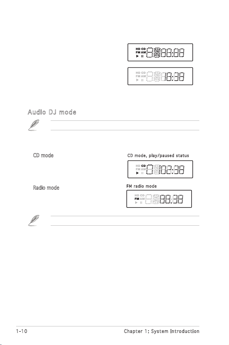
1.6 LED panel
The LED panel displays various system
information depending on the system
mode.
The LED panel displays the system
time in 24-hour format when the
system is in soft-off or stand-by
mode, S3 (Suspend-to-RAM), or S4
(Suspend-to-Disk) state. Enter the BIOS
setup or the operating system to adjust
the time.
Aud io D J m od e
CD m o d e, pl a y / pause d s tatus
FM r a d io mo d e
In Radio mode, the LED panel displays
the station preset number and station
frequency.
Refer to page 3-11 for details on the Audio DJ feature.
The LED panel displays various information when the system is in Audio DJ
mode.
In CD mode, the LED panel displays the
play/pause icon, number, and duration of
the audio CD track being played.
Refer to page 5-20 for details on setting the radio region.
Page 21
ASUS T2-PH2
MODE
Chapter 2
Basic installation
This chapter provides step-by-step
instructions on how to install
components in the system.
Page 22
2-2
Chapter 2: Basic installation
Onboard LED
SB_PWR
ON
Standby
Power
OFF
Powered
Off
®
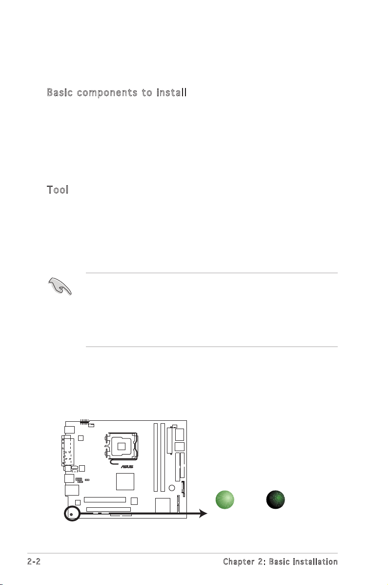
2.1 Preparation
Before you proceed, make sure that you have all the components you plan
to install in the system.
Bas i c c omp o ne n ts t o i nst a ll
1. Central Processing Unit (CPU)
2. DDR2 Dual Inline Memory Module (DIMM)
3. Expansion card(s)
4. Hard disk drive
5. Optical drive
6. Floppy disk drive
Too l
Phillips (cross) screw driver
The motherboard comes with an onboard standby power LED. This LED
lights up to indicate that the system is ON, in sleep mode or in soft-off
mode, and not powered OFF. Unplug the power cable from the power outlet
and make sure that the standby power LED is OFF before installing any
system component.
•
Use a grounded wrist strap or touch a safely grounded object or
a metal object, such as the power supply case, before handling
components to avoid damaging them due to static electricity.
•
Hold components by the edges to avoid touching the ICs on them.
•
Whenever you uninstall any component, place it on a grounded
antistatic pad or in the bag that came with the component.
2.2 Before you proceed
Take note of the following precautions before you install components into
the system.
Page 23
2-3
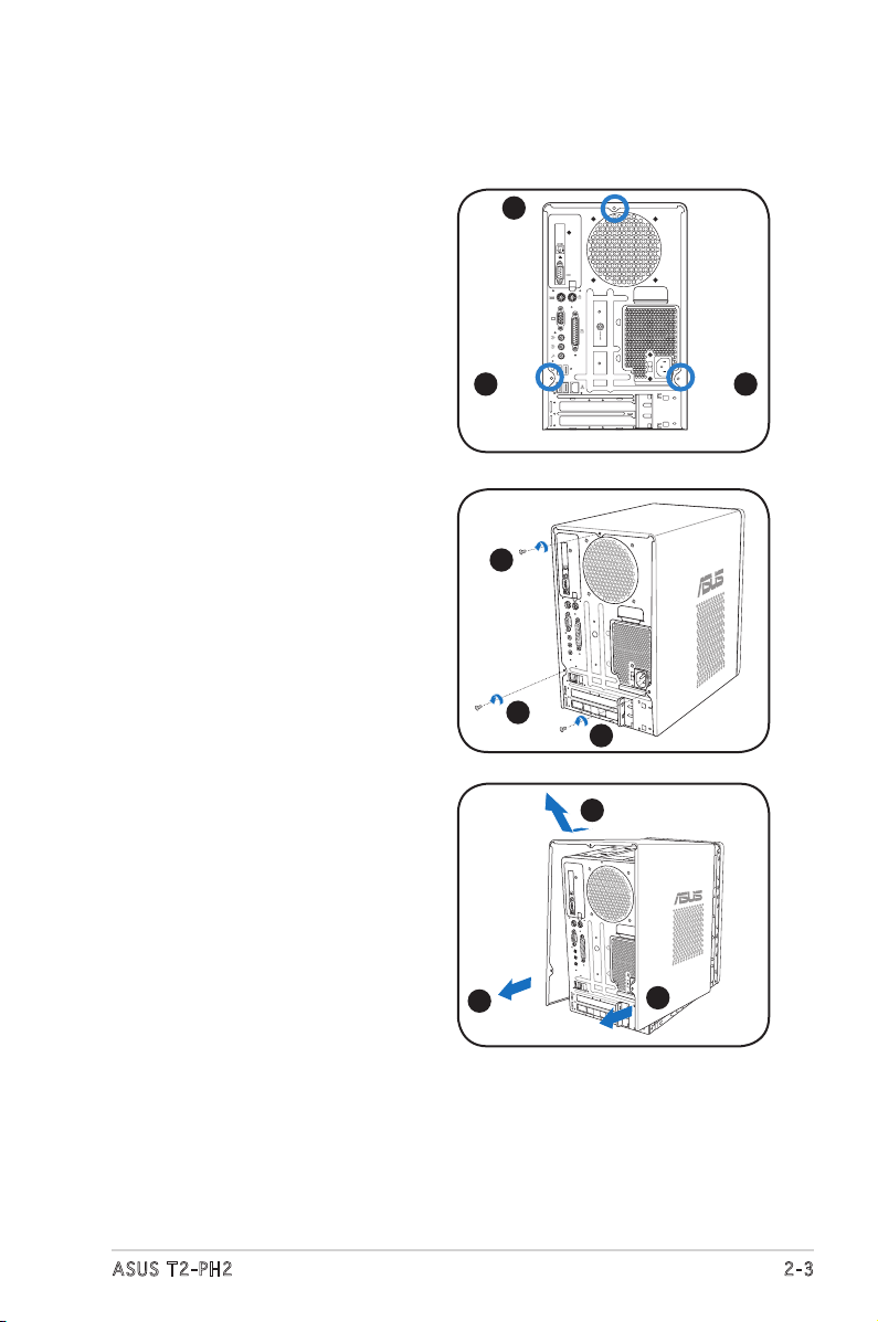
ASUS T2-PH2
3. Slightly pull the cover toward
the rear panel until the side
tabs are disengaged from the
chassis.
4. Lift the cover, then set aside.
2. Use a Phillips screw driver to
remove the cover screws. Keep
the screws for later use.
2.3 Removing the cover
To remove the cover:
1. On the rear panel, locate the
three screws that secure the
cover to the chassis.
2
2
2
1
1
1
4
3
3
Page 24
2-4
Chapter 2: Basic installation
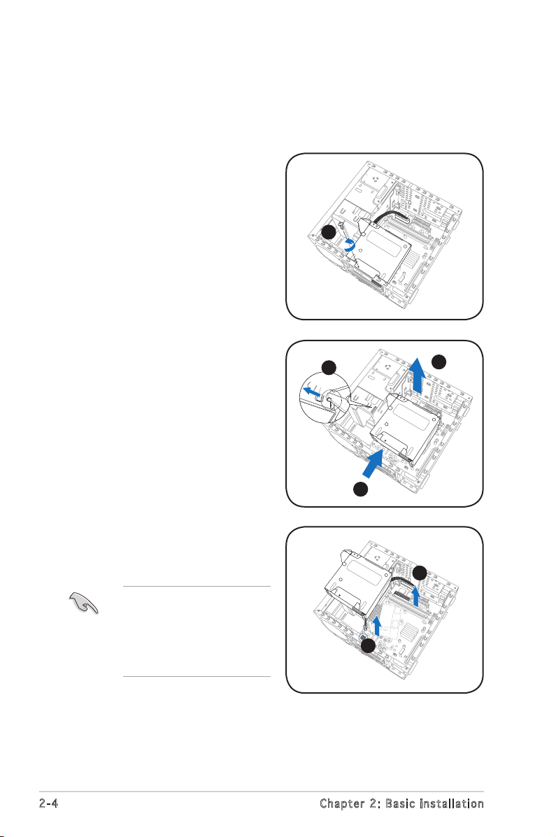
7. Disconnect the power plugs on
the motherboard, then set the
PSU aside.
4. Slide the PSU as the zoomed
image shows, until the side hook
is disengaged from the chassis.
5. Push the PSU towards the front
panel for about half an inch.
6. Slightly lift the PSU.
2.4 Removing the power supply
You must remove the power supply unit (PSU) before you can install a
central processing unit (CPU) and other system components.
To remove the PSU:
1. Lay the system on its side on a
flat, stable surface.
2. Disconnect the optical drive and
floppy disk drive power plugs.
3. Remove the screw that secures
the PSU to the chassis.
When removing the PSU,
make sure to hold or
support it firmly. The unit
may accidentally drop
and damage other system
components.
3
4
5
6
7
7
Page 25
2-5
ASUS T2-PH2
2.5 Installing a CPU
The ASUS motherboard comes with a surface mount LGA775 socket
designed for the Intel® Pentium® 4 processor in the 775-land package.
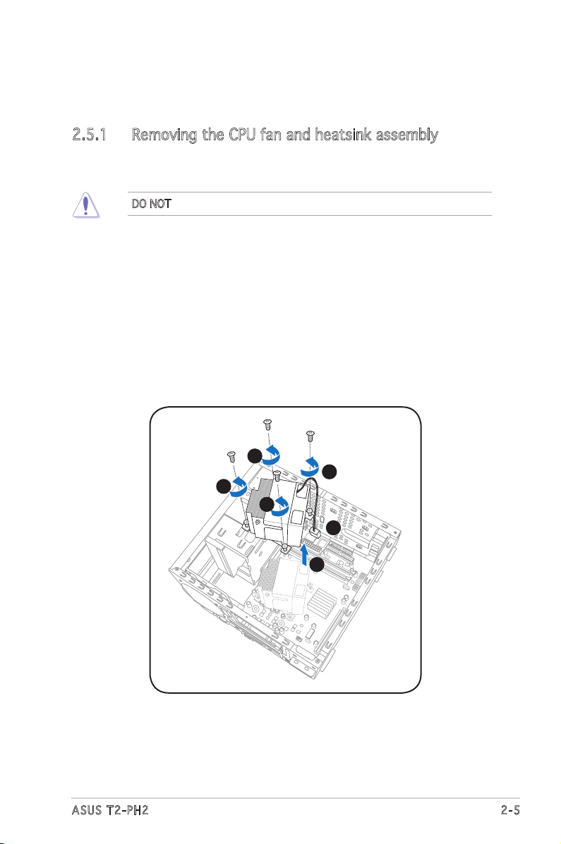
2.5.1 Removing the CPU fan and heatsink assembly
The system package includes a pre-installed proprietary CPU fan and
heatsink assembly to ensure optimum thermal condition and performance.
You must remove the CPU fan and heatsink assembly before you can install
a CPU.
To remove the CPU fan and heatsink assembly:
1. Disconnect the CPU fan cable from the CPU fan connector on the
motherboard.
2. Using a Phillips screw driver, remove and set aside the four screws
that secure the fan and heatsink assembly to the motherboard.
3. Carefully lift the fan and heatsink assembly, and set it aside.
DO NOT replace the proprietary CPU fan and heatsink with other models.
2
2
2
2
1
3
Page 26
2-6
Chapter 2: Basic installation
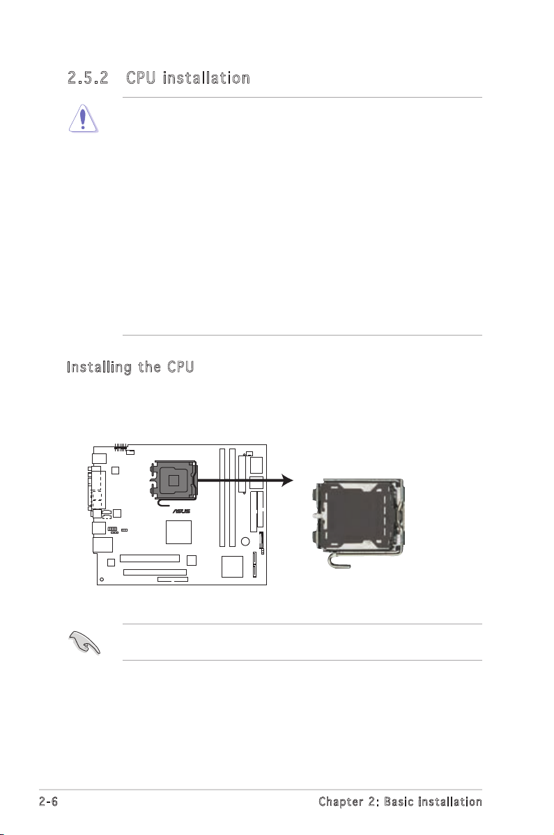
2.5 .2 CPU i ns tal la ti on
Ins t al l ing th e CP U
To install a CPU:
1. Locate the CPU socket on the motherboard.
Before installing the CPU, make sure that the socket box is facing
towards you and the load lever is on your left.
• Your boxed Intel® Pentium® 4 LGA775 processor package should
come with installation instructions for the CPU, heatsink, and the
retention mechanism. If the instructions in this section do not match
the CPU documentation, follow the latter.
•
Check your motherboard to make sure that the PnP cap is on the
CPU socket and the socket contacts are not bent. Contact your
retailer immediately if the PnP cap is missing, or if you see any
damage to the PnP cap/socket contacts/motherboard components.
ASUS will shoulder the cost of repair only if the damage is shipment/
transit-related.
•
Keep the cap after installing the motherboard. ASUS will process
Return Merchandise Authorization (RMA) requests only if the
motherboard comes with the cap on the LGA775 socket.
• The product warranty does not cover damage to the socket
contacts resulting from incorrect CPU installation/removal, or
misplacement/loss/incorrect removal of the PnP cap.
CPU Socket 775
®
Page 27
2-7
ASUS T2-PH2
To prevent damage to the
socket pins, do not remove
the PnP cap unless you are
installing a CPU.
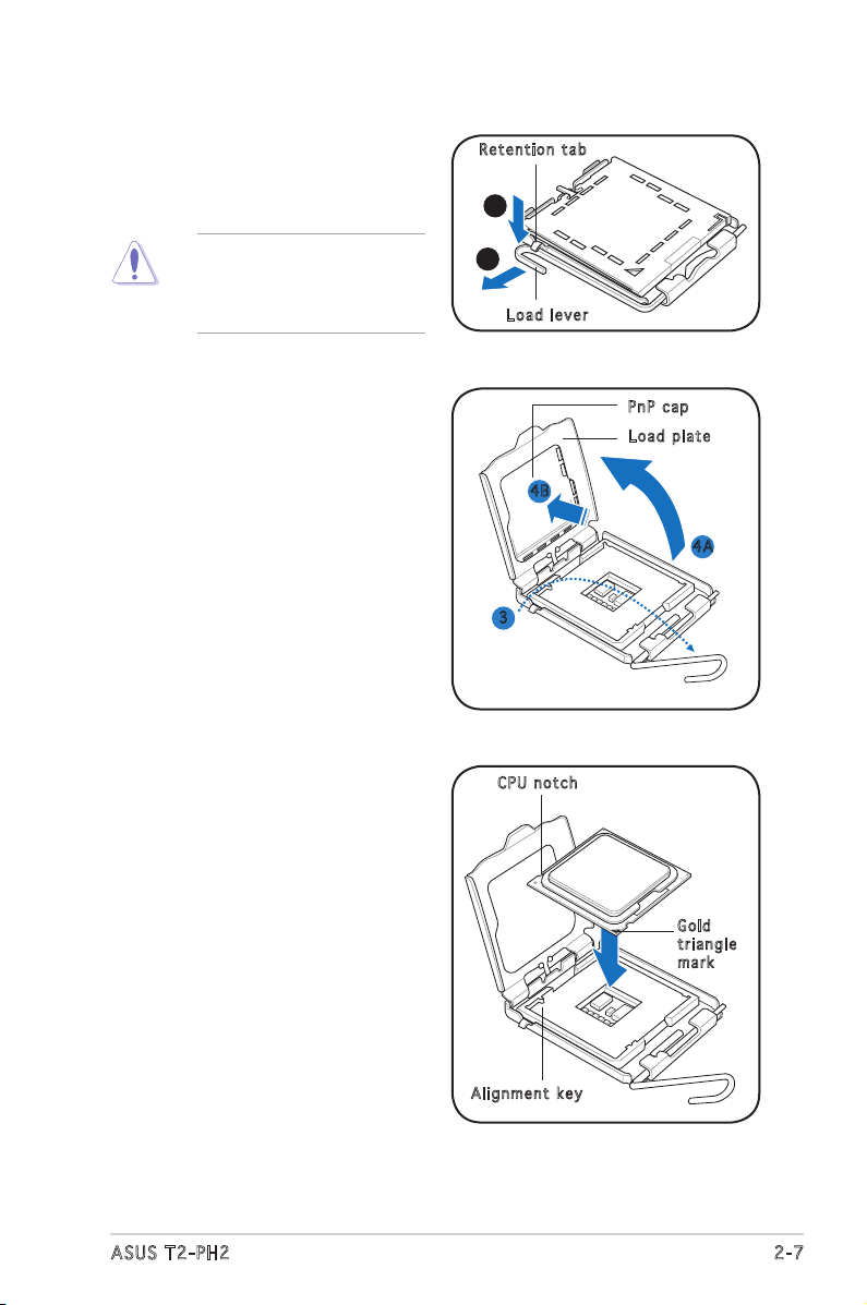
4. Lift the load plate with your
thumb and forefinger to a 100º
angle (4A), then push the PnP
cap from the load plate window
to remove (4B).
2. Press the load lever with your
thumb (A), then move it to the
left (B) until it is released from
the retention tab.
3. Lift the load lever in the
direction of the arrow to a 135º
angle.
A
B
Loa d l ever
Ret e n t ion t a b
Loa d p late
PnP c a p
4A
4B
3
5. Position the CPU over the
socket, making sure that
the gold triangle is on the
bottom-left corner of the socket
then fit the socket alignment
key into the CPU notch.
Gol d
tri a n g le
mar k
Ali g n m ent k e y
CPU n o tch
Page 28
2-8
Chapter 2: Basic installation
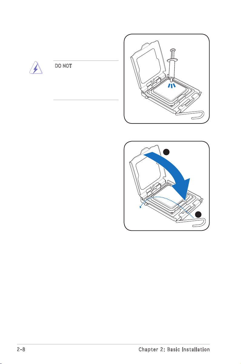
7. Close the load plate (A), then
push the load lever (B) until it
snaps into the retention tab.
6. Apply Thermal Interface Material
on the CPU before closing the
load plate.
A
B
DO NOT eat the Thermal
Interface Material. If it gets
into your eyes or touches
your skin, make sure to wash
it off immediately, and seek
professional medical help.
Page 29
2-9
ASUS T2-PH2
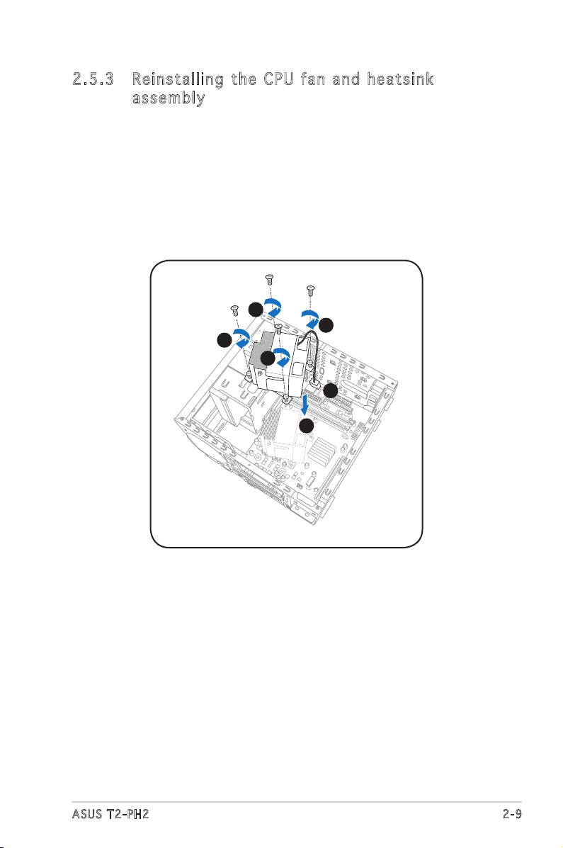
2.5 .3 Rei ns ta lli ng t he CP U fan a nd he at si nk
ass em bl y
To reinstall the CPU fan and heatsink assembly:
1. Position the CPU fan and heatsink assembly on top of the installed
CPU.
2. Drive in the four screws you removed earlier into the CPU fan screw
holes to secure the fan and heatsink assembly to the motherboard.
3. Connect the CPU fan cable to the CPU fan connector on the
motherboard.
2
2
2
2
3
1
Page 30
2-10
Chapter 2: Basic installation
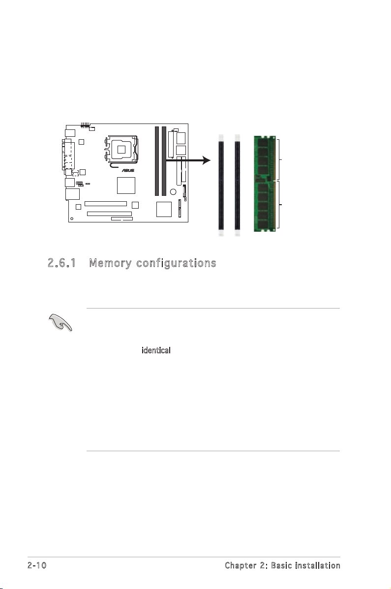
2.6 Installing a DIMM
The system motherboard comes with two Double Data Rate 2 (DDR2) Dual
Inline Memory Module (DIMM) sockets.
The following figure illustrates the location of the sockets:
• Installing DDR2 DIMMS other than the recommended configurations
may cause memory sizing error or system boot failure. Use any of
the recommended configurations in the table on the next page.
• Install only identical (the same type and size) DDR2 DIMMs in
DIMM_A1 and DIMM_B1.
• Always install DIMMs with the same CAS latency. For optimum
compatibility, we recommend that you obtain memory modules from
the same vendor.
• Due to chipset resource allocation, the system may detect less than
2 GB system memory when you installed two 1 GB DDR2 memory.
• This motherboard does not support memory modules made up of
128 Mb chips or double-sided x16 memory modules.
2.6 .1 Me m or y co n fi gu ra t io ns
You may install up to 2 GB system memory using 256 MB, 512 MB, and
1 GB DDR2 DIMMs.
240-pin DDR2 DIMM Sockets
DIMM_A1
DIMM_B1
112 Pins128 Pins
®
Page 31

2-11
ASUS T2-PH2
DDR 2 ( 5 33 M Hz) Qu a lif i ed Ven d or s Li s t
256 MB KINGSTON KVR533D2N4/256 Elpida SS E5116AB-5C-E • •
512 MB KINGSTON KVR533D2N4/512 Hynix DS HY5PS56821 • •
1024 MB KINGSTON KVR533D2N4/1G KINGSTON DS D6408TE7BL-37 • •
256 MB SAMSUNG M378T3253FG0-CD5 SAMSUNG SS K4T56083QF-GCD5 • •
256 MB SAMSUNG M378T6553BG0-CD5 SAMSUNG SS K4T51083QB-GCD5 • •
256 MB Infineon HYS64T32000HU-3.7-A Infineon SS
HYB18T512160AF-3.7AFSS31270
• •
512 MB Infineon HYS64T64000GU-3.7-A Infineon SS
HYB18T512800AC37SSS11511
• •
512 MB Infineon HYS64T64000HU-3.7-A Infineon SS
HYB18T512800AF37SSS12079
• •
512 MB Infineon HYS64T64000HU-3.7-A Infineon SS
HYB18T512800AF37FSS29334
• •
512 MB Micron
MT 16HTF6464AG-53EB2
Micron DS D9BOM • •
512 MB Micron
MT 16HTF6464AG-53EB2
Micron DS Z9BQT • •
1024 MB Micron
MT 16HTF12864AY-53EA1
Micron DS D9CRZ • •
512 MB CORSAIR VS512MB533D2 CORSAIR DS MIII0052532M8CEC • •
512 MB Elpida EBE51UD8ABFA-5C-E Elpida SS E5108AB-5C-E • •
256 MB Kingmax KLBB68F-36EP4 Elpida SS E5116AB-5C-E • •
512 MB Kingmax KLBC28F-A8KB4 Kingmax SS KKEA88B4IAK-37 • •
512 MB Kingmax KLBC28F-A8EB4 Kingmax SS E5108AE-5C-E • •
512 MB PQI MEAB-323LA PQI SS D2-E04180W025 • •
1024 MB PQI MEAB-423LA PQI DS D2-E04230W107 • •
512 MB MDT MDT 512MB MDT SS MDT18D51280D-3.70520 • •
1024 MB MDT MDT 1024 MB MDT DS MDT18D51280D-3.70518 • •
512 MB AENEON AET660UD00-370A98Z AENEON SS AET93F370A G 0513 • •
256 MB AENEON AET560UD00-370A98Z AENEON SS
AET94F370AWVV34635G0520
• •
512 MB AENEON AET660UD00-370A98Z AENEON SS
AET93F370A 3VV36328G 0522
• •
512 MB AENEON AET660UD00-370A98X AENEON SS AET93F370A 0518 • •
Siz e Ve n d or Mo d e l Bra n d S i d e / s* C o mpon e n t A B
DI M M suppo r t
* U s e only i d e ntica l D DR2 D I M M pair s .
Soc k e t s
Mod e D I M M_A1 DI M M _ B1
Single-channel (1) Installed —
(2) — Installed
Dual-channel (3)* Installed Installed
Rec o mm e nde d m e mor y c o nfi g ur a tio n s
Page 32

2-12
Chapter 2: Basic installation
256 MB KINGSTON E2508AB-6E-E Elpida SS KVR667D2N5/256 • •
512 MB KINGSTON KVR667D2N5/512 Kingston SS D6408TE8WL-27 • •
512 MB KINGSTON KVR667D2E5/512 Elpida SS E5108AE-6E-E • •
1024 MB KINGSTON KVR667D2N5/1G Kingston DS D6408TE8WL-3 • •
512 MB SAMSUNG KR M378T6553CZ0-CE6 SAMSUNG SS K4T51083QC • •
512 MB SAMSUNG KR M378T6453FZ0-CE6 SAMSUNG DS K4T56083QF-ZCE6 • •
1024 MB SAMSUNG KR M378T2953CZ0-CE6 SAMSUNG SS K4T51083QC-ZCE6 • •
256 MB Infineon HYS64T32000HU-3S-A Infineon SS
HYB18T512160AF-3SSSS17310
• •
512 MB Infineon HYS64T32000HU-3S-A Infineon SS
HYB18T5128000AF-3SSSS27416
• •
512 MB Infineon HYS64T64000HU-3S-A Infineon SS
HYB18T512800AF3SFSS05346
• •
1024 MB Infineon HYS64T128020HU-3S-A Infineon DS
HYB18T512800AF3SSSS28104
• •
512 MB CORSAIR VS512MB667D2 CORSAIR DS MIII0052532M8CEC • •
512 MB Hynix HYMP564U64AP8-Y4 AA Hynix SS HY5PS12821AFP-Y4 • •
512 MB Hynix HYMP564U64AP8-Y5 AA Hynix SS HY5PS12821AFP-Y5 • •
1024 MB Hynix HYMP512U64AP8-Y5 AB Hynix DS HY5PS12821AFP-Y5 • •
512 MB Kingmax KLCC28F-A8EB5 Elpida SS E5108AE-6E-E • •
512 MB Apacer 78.91092.420 Elpida SS E5108AE-6E-E • •
1024 MB Apacer 78.01092.420 Elpida DS E5108AE-6E-E • •
512 MB ADATA M20EL5G3H3160B1C0Z Elpida SS E5108AE-6E-E • •
256 MB Nanya NT256T64UH4A1FY-3C Nanya SS NT5TU32M16AG-3C • •
512 MB Nanya NT512T64U88A1BY-3C Nanya SS NT5TU64M8AE-3C • •
512 MB Patriot PDC21G5600+XBLK PDP SS N/A • •
1024 MB MDT MDT 1024 MB MDT DS MDT18D51280D-30528 • •
512 MB GEIT GX21GB5300DC GEIT SS Heat-Sink Package • •
512 MB Century CENTURY 512MB Nanya SS NT5TU64M8AE-3C • •
512 MB Century CENTURY 512MB Hynix SS HY5PS12821AFP-Y5 • •
1024 MB Century CENTURY 1G Hynix DS HY5PS12821AFP-Y5 • •
1024 MB Century CENTURY 1G Hynix DS NT5TU64M8AE-3C • •
Siz e Ve n d or Mo d e l Bra n d S i d e / s* Co m p o nent A B
DI M M suppo r t
DDR 2 ( 6 67 M Hz) Qu a lif i ed Ven d or s Li s t
Legend:
A - supports one module inserted into either slot, in a Single-channel memory
configuration.
B - supports one pair of modules inserted into either the blue slots or the black
slots as one pair of Dual-channel memory configuration.
SS - Single-sided
DS - Double-sided
Obtain DDR DIMMs only from ASUS qualified vendors. Refer to the
Qualified DDR2 533/667 vendors list on this page. Visit the ASUS
website (www.asus.com) for the latest DDR2 Qualified Vendors List.
Page 33

2-13
ASUS T2-PH2
2.6 .2 DIM M in sta ll at ion
To install a DDR2 DIMM:
1. Locate the two DIMM sockets
on the motherboard.
2. Unlock a socket by pressing
the retaining clips outward.
3. Align a DIMM on the socket
such that the notch on the
DIMM matches the break on
the socket.
4. Firmly insert the DIMM into the
socket until the retaining clips
snap back in place and the
DIMM is properly seated.
A DDR2 DIMM is keyed with a notch so that it fits in only one direction.
DO NOT force a DIMM into a socket to avoid damaging the DIMM!
Ret a i n ing c l i p s
1
2
2
3
4
4
Page 34

2-14
Chapter 2: Basic installation
2.7 Installing an expansion card
In the future, you may need to install expansion cards. The motherboard
has one PCI and one PCI Express™ x16 slot. The following sub-sections
describe the slots and the expansion cards that they support.
2.7 .1 Exp an si on sl ot s
Make sure to unplug the power cord before adding or removing
expansion cards. Failure to do so may cause you physical injury and
damage the motherboard.
PCI Ex p res s ™ x 16 s lot
This motherboard supports PCI
Express™ x16 graphic cards
that comply with PCI Express™
specifications. The figure shows a
graphics card installed on the PCI
Express™ x16 slot.
PCI sl o t
The PCI slots support PCI cards such
as a LAN card, SCSI card, USB card,
and other cards that comply with PCI
specifications. The figure shows a
LAN card installed on a PCI slot.
The chassis supports PCI Express x 16 cards with 204.63mm x 108mm x
16mm or smaller dimensions only.
Page 35

2-15
ASUS T2-PH2
2.7 .2 Exp an si on ca rd in st al lat io n
To install an expansion card.
1. Before installing the expansion card, read the documentation that
came with it and make the necessary hardware settings for the card.
2. Pull the expansion card lock to
the direction of the arrow.
3. Remove the metal cover
opposite the slot that you intend
to use.
5. Replace the expansion card
lock to secure the card to the
chassis.
4. Align the card connector with
the slot and press firmly until
the card is completely seated
on the slot.
Exp a n s ion
car d l ock
PCI
slo t
PCI E x press
x16 s l ot
2
Exp a n s ion c a r d
4
5
Me t a l cove r s
3
Page 36

2-16
Chapter 2: Basic installation
When using a PCI card on shared slots, ensure that the drivers support
“Share IRQ” or that the cards do not need IRQ assignments; otherwise,
conflicts will arise between the two PCI groups, making the system
unstable and the card inoperable.
Sta n da r d i n te r rup t a s sig n me n ts
IRQ Standa r d Funct i o n
0 System Timer
1 Keyboard Controller
2 Programmable Interrupt
4 Communications Port (COM1)
6 Floppy Disk Controller
7* Printer Port (LPT1)
8 System CMOS/Real Time Clock
9* ACPI Mode when used
10* IRQ Holder for PCI Steering
11* IRQ Holder for PCI Steering
12* PS/2 Compatible Mouse Port
13 Numeric Data Processor
14* Primary IDE Channel
* T h e s e IRQ s a re us u a l l y av a i l a ble f o r ISA o r P CI d e v i c es.
A B C D E F G H
PCI slot –– –– –– –– –– shared –– ––
PCI Express x16 slot shared –– –– –– –– –– –– ––
Onboard USB controller 1 –– –– –– –– shared –– –– ––
Onboard USB controller 2 –– shared –– –– –– –– –– ––
Onboard USB controller 3 –– –– shared –– –– –– –– ––
Onboard USB controller 4 –– –– –– shared –– –– –– ––
Onboard USB 2.0 controller –– –– –– –– shared –– –– ––
Onboard IDE port –– –– shared –– –– –– –– ––
Onboard ACʼ 97 Audio shared –– –– –– –– –– –– ––
Onboard LAN –– shared –– –– –– –– –– ––
Onboard 1394 –– –– –– –– –– shared –– ––
IRQ as s ign m en t s f o r t his mo t her b oa r d
Page 37

2-17
ASUS T2-PH2
2.8 Installing an optical drive
The barebone system comes with two 5.25-inch drive bays for two optical
drives.
To install an optical drive:
1. Place the chassis upright.
2. Locate the front panel cover
hooks.
3. To remove the front panel cover
from the chassis, press the
top hooks downward and the
bottom hooks upward to release
them from the metal tabs that
secure them in place.
4. Detach the front panel cover
top hooks.
5. Slightly push the front panel
cover outward until it detaches
from the chassis, then set it
aside.
On Deluxe models, disconnect
the LED panel and the front
audio button panel cables from
their respective connectors
before removing the front
panel cover.
To reconnect the cables, see
pages 4-12 for the location of
the connectors.
• You may install a second optical drive only if you installed a Serial
ATA hard disk drive.
• Set your second optical drive as Slave device before connecting the
IDE cable and power plug. Refer to the optical drive documentation
on how to set the drive as a Slave device.
1
2
3
3
3
3
4
4
5
Page 38

2-18
Chapter 2: Basic installation
6. Carefully push the optical drive into the bay until its screw holes align
with the holes on the bay as
shown.
7. Secure the optical drive with
two screws on one side of the
bay.
6
7
8. Connect a power cable from the
power supply unit to the power
connector at the back of the
optical drive. See page 2-25 for
details on the power supply unit
plugs.
9. Connect the IDE ribbon cable to
the IDE interface at the back of
the optical drive, matching the red
stripe on the cable with Pin 1 on
the IDE interface.
10. Connect one end of the optical
drive audio cable to the 4-pin
connector at the back of the
optical drive.
11. Make sure that the other end of
the IDE ribbon cable is connected
to the primary IDE connector (blue
connector labeled PRI_IDE) on the
motherboard. See page 4-8 for
the location of the primary IDE
connector.
12. Connect the other end of the
audio cable to the 4-pin CD
connector on the motherboard.
See page 4-10 for the location of
the CD audio connector.
8
9
10
Page 39

2-19
ASUS T2-PH2
14. Lock the front panel cover
hooks to the chassis holes as
indicated.
14
Reconnect the LED panel and
the front audio button panel
cables to their respective
connectors before reinstalling
the front panel cover.
See pages 4-12 for the
location of the connectors.
13. Reinstall the front panel cover
by aligning its hooks with the
chassis holes.
13
Page 40

2-20
Chapter 2: Basic installation
2.9 Installing a floppy disk drive
The barebone system comes with one 3.25-inch drive bay for a floppy disk
drive.
To install a floppy disk drive:
1. Remove the front panel cover.
For instructions on how
to remove the front panel
cover, refer to steps 1-5
of section “2.8 Installing an
optical drive”.
2. Carefully insert the floppy disk
drive into the floppy drive bay
until the screw holes align with
the holes on the bay.
3. Secure the floppy disk drive with
two screws.
2
3
3
4
6
4. Connect the floppy disk drive
signal cable to the signal
connector at the back of the
drive.
5. Connect the other end of the
signal cable to the floppy disk
drive connector (labeled FLOPPY)
on the motherboard. See page
4-10 for the connector location.
6. Connect a power cable from the
power supply unit to the power
connector at the back of the floppy
disk drive. See page 2-25 for details
on the power supply unit plugs.
Page 41

2-21
ASUS T2-PH2
Configure your hard disk drive as Master device before connecting the
IDE cable and power plug. Refer to the HDD documentation on how to
set the drive as a Master device.
2.10 Installing a hard disk drive (HDD)
The system supports one Ultra ATA/100 IDE or one Serial ATA hard disk
drive.
To install an IDE hard disk drive:
1. Locate the HDD tray lock screw
on the other side of the chassis.
2. Remove the lock screw with a
Philips screw driver. Keep the
screw for later use.
4. Place a hard disk drive on the
tray with its bottom on the
open side. Align the HDD and
HDD tray screw holes.
5. Secure the HDD with four
screws.
3. Slide the HDD tray outward until
the tray slots are released from
the chassis hooks.
4
5
5
1
2
Tra y l ocks
Loc k s lots
3
Tra y l ocks
Page 42

2-22
Chapter 2: Basic installation
6. Reinstall the tray and the HDD
to the chassis by locking the
tray slots to the chassis hooks.
7. Secure the tray with the screw
you removed earlier.
8. Connect one end of the 40-pin
IDE cable to the IDE connector
on the drive.
9. Connect a 4-pin power plug
from the power supply unit to
the HDD power connector. See
page 2-25 for details on the
power supply unit plugs.
10. Connect the other end of the
IDE ribbon cable to the primary
IDE connector (blue connector
labeled PRI_IDE) on the
motherboard. See page 4-8 for
the location of the primary IDE
connector.
6
7
8
9
Page 43

2-23
ASUS T2-PH2
To install a Serial ATA hard disk drive:
1. Follow steps 1-7 of the previous section.
2. Connect one end of the supplied
7-pin SATA cable (right angle
side) to the SATA connector
at the back of the drive,
then connect the other end
to a SATA connector on the
motherboard. See page 4-9 for
the location of the Serial ATA
connectors.
2
2
3a
3b
15- p i n SATA
pow e r plug
4-p i n (male )
pow e r plug
If your Serial ATA HDD has both 4-pin and 15-pin connectors at the
back, use either the 15-pin SATA power adapter plug OR the legacy
4-pin power connector. DO NOT use both to prevent damage to
components and to keep the system from becoming unstable.
3. For Serial ATA HDDs with a 4-pin
power connector:
a. Connect a 4-pin (female) power plug from the power supply unit
to the 4-pin (male) power connector at the back of the drive. See
page 2-25 for details on the power supply unit plugs.
For Serial ATA HDDs without a 4-pin power connector:
b. Connect the 15-pin SATA power adapter plug to the power
connector at the back of the drive, then connect the other end
(4-pin male) to a 4-pin (female) power plug from the power supply
unit. See page 2-25 for details on the power supply unit plugs.
Page 44

2-24
Chapter 2: Basic installation
2.11 Reinstalling the power supply unit
Reinstall the power supply unit (PSU) after installing the system
components and reconnecting the cables.
To reinstall the PSU:
1. Connect the 4-pin 12 V power
plug to the ATX12V connector
on the motherboard.
2. Connect the 24-pin ATX power
plug to the ATXPWR connector
on the motherboard. See page
4-7 for the location of power
connectors.
3. Position the PSU over the
chassis.
4. Align the PSU side hook with the
metal slot located on the side of
the optical drive bay.
5. Slide the PSU toward the
direction of the rear panel until it
fits in place.
6. Secure the PSU with the screw
you removed earlier.
Make sure the PSU cables do
not interfere with the CPU
and/or chassis fans.
2
1
6
4
3
5
Page 45

2-25
ASUS T2-PH2
7. Connect the 4-pin power plug to the power connector of the floppy
disk drive.
8. Connect the 4-pin power plug(s) to the power connector of the
optical drive(s).
9A. Connect the 4-pin power plug to the power connector of the IDE hard
disk drive, or the Serial ATA hard disk drive with a 4-pin power plug.
- or -
9B. For Serial ATA hard disk drive without a 4-pin power plug, connect
the 15-pin SATA power adapter plug to the power connector at the
back of the drive, then connect the other end (4-pin male) to a 4-pin
(female) power plug from the power supply unit.
Vol ta ge se le ct or
The PSU has a 115 V/230 V voltage selector
switch located beside the power connector. Use
this switch to select the appropriate system
input voltage according to the voltage supply in
your area.
If the voltage supply in your area is 100-127 V,
set the switch to 115 V.
If the voltage supply in your area is 200-240 V,
set the switch to 230 V.
230
Setting the switch to 115 V in a 230 V environment will seriously
damage the system!
See the Appendix for the power supply specifications.
Pow e r suppl y u nit p l u g s
2
7
8
9B
9A
1
Page 46

2-26
Chapter 2: Basic installation
2.12 Replacing the cover
To replace the cover:
1. Turn the chassis upright.
2. Position the front edge of the
cover at least two inches from
the front panel cover. Fit the
cover tabs with the chassis rail
and the front panel tabs.
3. Lower the rear edge of the
cover as shown.
4. Push the cover slightly toward
the front panel until it fits in
place.
5. Secure the cover with the three
screws you removed earlier.
2
3
4
5
Page 47

ASUS T2-PH2
MODE
Chapter 3
Starting up
This chapter helps you power up
the system and install drivers and
utilities from the support CD.
Page 48

3-2
Chapter 3: Starting up
3.1 Installing an operating system
The barebone system supports Windows® 2000/XP operating systems
(OS). Always install the latest OS version and corresponding updates so
you can maximize the features of your hardware.
3.3 Support CD information
The support CD that came with the system contains useful software and
several utility drivers that enhance the system features.
3.2 Powering up
The system has two power buttons located on the front panel. Press the
system power button ( ) to enter the OS. Press the button to turn on
the Audio DJ feature.
Pre s s to pu t t he sy s t e m in
Aud i o D J mo d e
Pre s s to en t e r the
sys t e m OS
Because motherboard settings and hardware options vary, use the setup
procedures presented in this chapter for general reference only. Refer to
your OS documentation for more information.
In Windows® mode, pressing the button shuts down, restarts, or puts
the system in sleep mode (S3) depending on the OS setting.
•
Screen display and driver options may not be the same for other
operating system versions.
•
The contents of the support CD are subject to change at any time
without notice. Visit the ASUS website for updates.
MODE
Page 49

3-3
ASUS T2-PH2
3.3 .1 Run ni ng th e su ppo rt C D
To begin using the support CD, place the CD in your optical drive. The
CD automatically displays the Drivers menu if Autorun is enabled in your
computer.
If Autorun is NOT enabled in your computer, browse the contents of the
support CD to locate the file ASSETUP.EXE from the BIN folder.
Double-click the ASSETUP.EXE to run the CD.
3.3 .2 Dri ve rs me nu
The drivers menu shows the available device drivers if the system detects
installed devices. Install the necessary drivers to activate the devices.
QFE Up d ate
Installs the Quick Fix Engineering (QFE) driver updates.
Cli c k an it e m to in s t a ll
Cli c k an ic o n to di s p l ay
oth e r infor m a t ion
Make sure you install the QFE Update only
before
installing Microsoft®
Windows® XP Service Pack 1.
Int e l C hip s et INF Up d ate Pr o gra m
Installs the Intel® Chipset INF Update Program.
Page 50

3-4
Chapter 3: Starting up
3.3 .3 Uti li ti es me nu
The Utilities menu shows the applications and other software that the
motherboard supports.
Int e l( R ) G r ap h ics Ac c ele r at o r D r iv e r
Installs the Intel® graphics accelerator driver.
Rea l te k Au d io Dri v er
Installs the Realtek® AC`97 audio driver.
Mar v el l Yu k on Gig a bi t Et h er n et D ri v er
Installs the Marvell® Gigabit LAN Driver.
ASU S P C Pr o be II
This smart utility continuously monitors vital system information such as
fan rotations, CPU temperature, and system voltages, and alerts you on
any detected problems. This utility helps you keep your computer in a
healthy operating condition.
Page 51

3-5
ASUS T2-PH2
ASU S Up dat e
Installs the ASUS Update that allows you to update the motherboard BIOS
and drivers. This utility requires an Internet connection either through a
network or an Internet Service Provider (ISP). See page 5-8 for details.
ASU S S c ree n sa v er
Bring life to your idle screen by installing the ASUS Screensaver.
ASU S R a dio Pl a yer
Installs the ASUS radio application that allows you to tune in to an FM radio
station. See page 3-7 for details.
Ado b e A cro b at Rea d er V7. 0
The Acrobat® Acrobat Reader® software is for viewing files saved in
Portable Document Format (PDF).
Mic r os o ft D ir e ctX 9. 0 c
Installs Microsoft® DirectX® 9.0c. The Microsoft® DirectX® 9.0c is a
multimedia techology that enhances computer graphics and sounds.
DirectX® improves the multimedia featuers of your computer so you can
enjoy watching TV and movies, capturing videos, or playing games on your
computer.
This application is already built into the Microsoft® Windows® XP Service
Pack 2. If Microsoft® Windows® XP Service Pack 2 is installed in your
system, skip Microsoft® DirectX® 9.0c installation.
Nor t on Ant i -v i rus ut i lit y
The Norton anti-virus application scans, identifies, and removes computer
viruses. View the online help for detailed information.
Page 52

3-6
Chapter 3: Starting up
3.3 .5 Oth er i nfo rm at ion
The icons on the top right side of the screen provide additional information
on the motherboard and the contents of the support CD.
3.3 .4 ASU S co nta ct i nfo rm at ion
The Contact tab displays the ASUS contact information.
Page 53

3-7
ASUS T2-PH2
3.4 .1 ASU S Ra dio P la yer
ASUS Radio Player allows you to tune in to an FM station using the optional
radio module.
Lau n ch i ng t he ASU S R a dio Pl a yer
To launch the ASUS Radio Player:
1. Install the ASUS Radio Player from the Utilities tab of the support CD.
See page 3-4 for details.
2. After installing the application, click Start > All Programs > ASUS >
ASUS Radio Player V1.0 > ASUS Radio Player V1.0 from the Windows®
desktop.
3. The ASUS Radio Player panel appears.
By default, the radio region of the ASUS FM radio module is set to
Europe. If you purchased the barebone system outside Europe (USA or
Japan), you must change the radio region in the BIOS setup to receive
FM radio signals. See section “5.4.1 Instant Music Configuration” for
details.
3.4 Software information
Most of the applications in the support CD have wizards that will
conveniently guide you through the installation. View the online help or
readme file that came with the software for more information.
Tun e l eft
Scan left
Sto p
Sca n r ight
Tun e r ight
Clo s e ASUS R a d io
Minimi ze A SU S Radio
Pow e r butto n
Sta t i o n fre q u e ncy
In creas e the vo lu me
Decrease the volume
Mute/Sound on button
Sto r e butto n
Clo c k
Edi t b utton
Pre s e t stat i o n list
Page 54

3-8
Chapter 3: Starting up
Sto r in g a r ad i o s t at i on
To store a radio station:
1. Use the Scan or Tune buttons
to tune into a radio station you
wish to store.
2. Click the Store button. A Store
Channel window appears.
3. Assign a Channel (preset
number) to the radio station
using the arrow buttons.
4. Type the station name in the
field, then click OK.
5. The stored channel is displayed in the preset station list.
3. Another Edit Channel window
appears.
4. Edit the station frequency and
name.
Click OK when you are done.
Edi t in g a s to r ed r ad i o
To edit a stored radio station:
1. Click the Edit button. An Edit
Channel window appears.
2. Select a radio station you want
to edit, then click the Edit
button.
Page 55

3-9
ASUS T2-PH2
To e na b le A SU S In s ta n t M u si c :
1. Connect the analog audio cable from the optical drive to the 4-pin CD
connector on the motherboard. See section “4.4 Connectors” for the
location of the CD connector.
3.4 .2 ASU S In sta nt M usi c
The motherboard is equipped with a BIOS-based audio playback feature
called Instant Music. The onboard audio ACʼ97 CODEC supports this
feature, which requires an optical drive (CD-ROM, DVD-ROM, or CD-RW).
2. Turn on the system and enter BIOS by pressing the Delete key during
the Power-On Self-Test (POST).
3. In the Instant Music Configuration menu, select the item Instant Music
and set it to Enabled. See section “5.4.1 Instant Music Configuration.”
4. The Instant Music CD-ROM Drive item appears if you enabled Instant
Music. Highlight the item then press <Enter> to display the CD-ROM
options.
5. Save your changes and exit BIOS Setup.
Make sure to connect the optical drive audio cable. Otherwise, you
cannot control the audio volume using the Instant Music function keys.
•
The Scroll Lock LED is fixed to ON after enabling Instant Music.
•
The Caps Lock LED turns ON when you pause the CD playback.
•
When set to Instant Music mode, the system wake-up features
(LAN, keyboard, mouse, USB) are deactivated. In this case, power up
the system using the power switch.
•
If the system lost connection or did not detect any optical drive, the
Instant Music feature turns OFF (disabled) automatically. A “beep”
indicates this condition.
•
Instant Music only supports CDs in audio format.
•
Instant Music does not work if you installed and enabled an add-on
sound card.
•
Instant Music only supports PS/2 keyboard.
Page 56

3-10
Chapter 3: Starting up
To use ASUS Instant Music:
1. Connect the PC power plug to an electrical outlet.
2. Use either one of the two sets of special function keys on your
keyboard to play audio CDs. These keys only function as indicated if
you enabled the Instant Music item in BIOS.
I n s t ant M u s i c fun c t i on ke y s (Set 2 )
CD ON/OFF
PLAY/PAUSE
STOP/EJECT
PREVIOUS NEXT
VOL. DOWN VOL. UP
SCROLL
LOCK
LED
CAPS
LOCK
LED
3. Connect the speakers to the Line Out (lime) port on the rear panel for
audio output. You may also connect a headphone to the headphone
port on the rear/front panel or on the optical drive front panel.
4. Press <Esc> to turn on Instant Music.
5. Insert an audio CD to the optical drive.
6. Press <F1> or the <Space Bar> to play the first track on the audio CD.
7. Refer to the Instant Music keyboard label to select other tracks or
control the volume.
8. Press <F2> or <Enter>
once
to stop playing the audio CD.
Press <F2> or <Enter>
again
to eject the CD.
If there is no audio CD inside the optical drive, the drive tray ejects when
you press <F1> or <Space Bar>.
CD
ON/OFF
PLAY/PAUSE STOP/EJECT PREVIOUS NEXT VOL. DOWN VOL. UP
Esc F1 F2 F3 F4 F5 F6 F7 F8
To guide you in using Instant Music, place the Instant Music label over
the function keys on the keyboard. The Instant Music keyboard label
comes with your motherboard package.
I n s t ant M u s i c fun c t i on ke y s (Set 1 )
Page 57

3-11
ASUS T2-PH2
3.5 Audio DJ
Audio DJ is an application that allows you to play audio CD/DVD or tune
into an FM radio station without entering the operating system.
To put the system in Audio DJ mode:
1. Connect the system power plug to an electrical outlet.
2. Press the CD button ( ) on the front panel to put the system in
Audio DJ mode.
3.5 .1 Pla yi ng an a ud io CD /D VD
To play an audio CD/DVD:
1. Insert an audio CD/DVD to the optical drive.
2. Press the PLAY/PAUSE ( / ) button to start playing the first track of
the audio CD/DVD.
3. Press the NEXT (
) or the PREVIOUS (
) button to skip to the next
track or return to the previous track.
4. Press the STOP ( ) button to stop playing the audio track.
3.5 .2 Tun in g int o an FM r ad io st at ion
Refer to page 5-20 for details on setting the radio region.
To tune into an FM station:
1. Press the MODE button to put Audio DJ in radio mode.
2. Press the PLAY/PAUSE ( / ) button for less than 2 seconds to scan
available radio stations in your location. The station scanning stops
when a station is detected.
3. Press the NEXT (
) or the PREVIOUS (
) button to select a preset
station, if any.
Page 58

3-12
Chapter 3: Starting up
3.5 .3 Pre se tt ing a s tat io n
To preset a radio station:
1. Put the Audio DJ in radio mode.
2. Select the radio station you wish to preset by pressing the PLAY/
PAUSE ( / ) button for less than 2 seconds.
3. After selecting the radio station, press the PLAY/PAUSE ( / ) button
for more than 2 seconds or until the station frequency display in the
LED panel blinks.
4. Use the NEXT (
) button or the PREVIOUS (
) button to select a
preset number (1 ~ 9) for the selected station.
5. Press the PLAY/PAUSE ( / ) button to assign the preset number to
the radio station.
Connect a headphone or PC speakers to the rear or front panel Line Out
port for audio output.
3.5 .4 Adj us ti ng th e vol um e
Press the ( +) button to increase the volume or the ( –) button to
decrease the volume.
Page 59

ASUS T2-PH2
MODE
Chapter 4
Motherboard info
This chapter gives information
about the motherboard that comes
with the system. This chapter
includes the motherboard layout,
jumper settings, and connector
locations.
Page 60

4-2
Chapter 3: Starting up
4.1 Introduction
The ASUS T2-PH2 motherboard comes already installed in the ASUS
T2-PH2 system. This chapter provides technical information about the
motherboard for future upgrades or system reconfiguration.
4.2 Motherboard layout
CD
ALC655
AUX
®
IOC_MB
Super
I/O
Flash
BIOS
PS/2
T:Mouse
B:Keyboard
ATX12V
BUZZ
CLRTC
PRI_IDE
24.89cm (9.8in)
20.06cm (7.9in)
DDR2 DIMM_A1 (64/72-bit, 240-pin module)
DDR 2 DIMM_B1 (64/72-bit, 240-pin module)
SB_PWR
FP_AUDIO
PANEL
FANPWR1
SPDIF_IN
Intel
ICH7
EATXPWR
SATA2
SATA1
USB12
PARALLEL PORT
VGA1
Mic
In
Line
Line
Out
LGA775
LAN_USB34
CPU_FAN
Intel
945G
PCI1
PCIEX16
CHA_FAN
Marvell
88E8053
BAT
FLOPPY
TI
TSB43AB22A
In
LGA775
Page 61

4-3
ASUS T2-PH2
4.3 Jumpers
1. Clea r R TC R A M (CLR T C )
This jumper allows you to clear the Real Time Clock (RTC) RAM in
CMOS. You can clear the CMOS memory of date, time, and system
setup parameters by erasing the CMOS RTC RAM data. The onboard
button cell battery powers the RAM data in CMOS, which include
system setup information such as system passwords.
To erase the RTC RAM:
1. Turn OFF the computer and unplug the power cord.
2. Remove the onboard battery.
3. Move the jumper cap from pins 1-2 (default) to pins 2-3. Keep the
cap on pins 2-3 for about 5~10 seconds, then move the cap back
to pins 1-2.
4. Re-install the battery.
5. Plug the power cord and turn ON the computer.
6. Hold down the <Del> key during the boot process and enter BIOS
setup to re-enter data.
Except when clearing the RTC RAM, never remove the cap on CLRTC
jumper default position. Removing the cap will cause system boot failure!
Clear RTC RAM
CLRTC
Normal Clear CMOS
(Default)
3
2
2
1
®
Page 62

4-4
Chapter 3: Starting up
2. Fan p o w er j u m p er ( 3 - p in F A N P WR1)
This jumper allows you to enable or disable the ASUS Q-Fan function.
®
FANPWR1
3
2
2
1
Disable Q-FANEnable Q-FAN
(Default)
Fan Power
Page 63

4-5
ASUS T2-PH2
4.4 Connectors
This section describes and illustrates the connectors on the motherboard.
See page 1-7 for the description of rear panel connectors.
1. Fron t p anel a u dio c o n nect o r (10- 1 p in F P _ A U DIO)
This interface is for the front panel audio connector (FP_AUD) on the
front panel I/O daughterboard to support the front panel audio I/O
ports.
2. Digi t a l aud i o conn e c t or ( 4 - 1 pin S P DIF_ I N )
This connector is for the SPDIF_IN connector on the front panel I/O
daughterboard to support the front panel S/PDIF In port.
®
Digital Audio Connector
+5V
SPDIFIN
GND
SPDIF_IN
®
Front Panel Audio Connector
FP_AUDIO
BLINE_OUT_L
MIC2
Line out_R
Line out_L
BLINE_OUT_R
NC
MICPWR
+5VA
AGND
Page 64

4-6
Chapter 3: Starting up
4. I/O e x t ensi o n modu l e (14- p i n IOC _ M B )
This connector is for the CS-T2 extension module. The CS-T2
extension module supports the rear panel S/PDIF Out and serial ports.
3. CPU a n d cha s s i s fa n c onne c t o rs
(3-p i n CPU_ F A N , CH A _ F AN)
The fan connectors support the proprietary CPU fan and chassis fan.
Connect the fan cables to the fan connectors on the motherboard,
making sure that the black wire of each cable matches the ground pin
of the connector.
Do not forget to connect the fan cables to the fan connectors.
Insufficient air flow within the system may damage the motherboard
components. These are not jumpers! DO NOT place jumper caps on the
fan connectors!
Fan Connectors
CHA_FAN
GND
SYSFANIN
CPUFANPWR
CPU_FAN
GND
CPU FAN PWR
CPU FAN IN
CPU FAN PWM
®
®
IOC_MB connector
®
COM1
IOC_DC
SPDIF_OUT
CS-T2
Page 65

4-7
ASUS T2-PH2
Do not forget to connect the 4-pin ATX12V power plug to the ATX12V
connector on the motherboard; otherwise, the system will not boot up.
5. ATX p o w er c o n n ecto r s (24 - p i n AT X P W R, 4 - p i n AT X 1 2 V )
These connectors are for the 24-pin and 4-pin power plugs from the
power supply unit. The plugs from the power supply unit are designed
to fit these connectors in only one orientation. Find the proper
orientation and push down firmly until the connectors completely fit.
®
ATX Power Connectors
EATXPWR
+12V DCGND
+12V DCGND
+3 Volts
+3 Volts
Ground
+5 Volts
+5 Volts
Ground
Ground
Power OK
+5V Standby
+12 Volts
-5 Volts
+5 Volts
+3 Volts
-12 Volts
Ground
Ground
Ground
PSON#
Ground
+5 Volts
+12 Volts
+3 Volts
+5 Volts
1
Ground
ATX12V
Page 66

4-8
Chapter 3: Starting up
6. IDE c o n nect o r (40- 1 p in P R I _ I DE)
This connector is for an Ultra DMA 100/66 signal cable. The Ultra
DMA 100/66 signal cable has three connectors: a blue connector for
the primary IDE connector on the motherboard, a black connector for
an Ultra DMA 100/66 IDE slave device (optical drive/hard disk drive),
and a gray connector for an Ultra DMA 100/66 IDE master device
(hard disk drive). Refer to the hard disk documentation for the jumper
settings.
• Pin 20 on the IDE connector is removed to match the covered hole
on the Ultra DMA cable connector. This prevents incorrect insertion
when you connect the IDE cable.
• Use the 80-conductor IDE cable for Ultra DMA 100/66 IDE devices.
IDE Connector
NOTE: Orient the red markings
(usually zigzag) on the IDE
ribbon cable to PIN 1.
PIN1
PRI_IDE
®
Page 67

4-9
ASUS T2-PH2
7. Seri a l ATA c o n nect o r s
( 7-pi n S ATA1 [ b lue] , S ATA2 [ b lue] )
These connectors are for the Serial ATA signal cables for Serial ATA
hard disk drives.
Important notes on Serial ATA
• You must install Windows® 2000 Service Pack 4 or the Windows®
XP Service Pack 1 before using Serial ATA hard disk drives.
• When using the connectors in Standard IDE mode, connect the
primary (boot) hard disk drive to the SATA1 or SATA2 connector.
Refer to the table below for the recommended SATA hard disk drive
connections.
Seri a l ATA h a r d di s k driv e c onne c t i on
Con n e c tor Color Set t i n g Use
SATA1 Black Master Boot disk
SATA2 Black Slave Data disk
SATA Connectors
SATA2
GND
RSATA_TXP2
RSATA_TXN2
GND
RSATA_RXP2
RSATA_RXN2
GND
SATA1
GND
RSATA_TXP1
RSATA_TXN1
GND
RSATA_RXP1
RSATA_RXN1
GND
®
Page 68

4-10
Chapter 3: Starting up
8. Inte r n a l au d i o con n e c tors ( 4 -pin A U X, C D )
These connectors allow you to receive stereo audio input from sound
sources such as a CD-ROM, TV tuner, or MPEG card.
9. Flop p y disk d r ive c o n nect o r (34- 1 p in F L O P PY)
This connector is for the provided floppy disk drive (FDD) signal cable.
Insert one end of the cable to this connector, then connect the other
end to the signal connector at the back of the floppy disk drive.
Pin 5 on the connector is removed to prevent incorrect cable connection
when using an FDD cable with a covered Pin 5.
®
Internal Audio Connectors
AUX
(white)
CD
(black)
Right Audio Channel
Left Audio Channel
Ground
®
FLOPPY
NOTE: Orient the red markings on
the floppy ribbon cable to PIN 1.
PIN 1
Floppy Disk Drive Connector
Page 69

4-11
ASUS T2-PH2
10. S y s tem p a n el c o n n ecto r ( 36-1 p i n PA N E L )
This connector provides connection to the front panel USB
connectors, IEEE 1394 connectors, FM radio connector, and the panel
connector (8-1 pin connector on the front panel I/O daughterboard)
which accommodates several system front panel functions.
• Front panel IEEE 1394a connectors
Pins 1~10 are for the IEEE 1394a connectors on the front panel I/O
daughterboard to support the front panel IEEE 1394a ports.
• Front panel USB connectors
These connectors are for the USB connectors on the front panel I/O
daughterboard to support the USB 2.0 ports on the front panel.
• FM Radio connectors
These connectors are for the FM Radio connector (F_R) on the front
panel I/O panel to support the FM radio function.
• System power LED
These connectors are for the 2-pin system power LED connector of
the panel connector (8-1 pin) on the front panel I/O daughterboard.
Refer to section “Daughterboard connectors” on page 4-13 for
details.
• Hard disk drive activity LED
These connectors are for the 2-pin HDD Activity LED connector of the
panel connector (8-1 pin) on the front panel I/O daughterboard.
• Power/Soft-off button
This connector is for the system power button connector of the panel
connector (8-1 pin) on the front panel I/O daughterboard.
System Panel Connector
®
PANEL
GND
GND
GND
GND
GND
P_LED+
+5VSB
+5V
HD_LED-
P_LED-
SMB_DATA_MAINSMB_CLK_MAIN
PWRBTN#DJ_BTN#
RSMGPIO_PIC
GND
TPA0+
TPA0-
TPB0+
TPB0-
USB6+
USB6-
USB7+
USB7-
USB4+
USB4-
V USB56 FL
V USB78 FL
USB5+
USB5-
TPA1+
TPA1-
TPB1+
TPB1-
1394P0_+12V
IEEE 1394
1
USB
USB
F_R
IEEE 1394
(HD_LED+)
Page 70

4-12
Chapter 3: Starting up
1. USB c o n nect o r (10- 1 p i n US B 1 )
Pins 1~5 are for the connector on the storage card reader
daughterboard.
USB1
USB Power
USBP2
–
USBP2
+
GND
+5V
Power Botto
n
USB Powe
r
USBP1
–
USBP1
+
GND
NC
Front panel daughterboard
Storage card reader daughterboard
2. FM r a d i o co n n e ctor ( 2 0-1 p i n F_R )
This connector links the LED panel, the Adudio DJ Switch, and the
FM radio module. (A) is for the connector (6 pin PANEL) on the
LED panel, which displays various system information, depending on
the system mode. (B) is for the J1 connector (10-1 pin J1) on the
Audio DJ Switch to support the Audio DJ buttons. (C) is for the J11
connector (20-1 pin J11) on the FM radio module. (D) is for the F_R
connector.
Front panel daughterboard
FM Radio module
Audio DJ Switch
LED panel
(Reverse)
(Reverse)
(Obverse)
(Obverse)
A
B
C
D
Dau g ht e rbo a rd con n ec t ors
Page 71

4-13
ASUS T2-PH2
3. Pane l c onne c t o r (8 - 1 pin P A N EL)
This connector supports several chassis-mounted functions through
connection with the motherboard panel connector (36-1 pin). Refer to
the section “10. System Panel Connector (36-1 pin PANEL)” on page
4-11 for details.
• System power LED (2-pin PLED)
This 2-pin connector is for the system power LED. The system power
LED lights up when you turn on the system power, and blinks when
the system is in sleep mode.
• Hard disk drive activity (2-pin HDLED)
This 2-pin connector is for the HDD Activity LED. The IDE LED lights
up or flashes when data is read from or written to the HDD.
• Power/Soft-off button (1-pin PWR)
This connector is for the system power button. Pressing the power
button turns the system ON or puts the system in SLEEP or SOFT-OFF
mode depending on the BIOS settings. Pressing the power switch for
more than four seconds while the system is ON turns the system OFF.
* Requires an ATX power supply.
PWR+
PANEL
PLED+
GNDPLED-
NCHDLED+
HDLED-
PWR
PLED HDLED
Front panel daughterboard
Page 72

4-14
Chapter 3: Starting up
Page 73

1
ASUS T2-PH2
MODE
Chapter 5
BIOS setup
This chapter tells how to change
system settings through the BIOS
Setup menus and describes the
BIOS parameters.
Page 74

5-2
Chapter 5: BIOS setup
5.1 Managing and updating your BIOS
The following utilities allow you to manage and update the motherboard
Basic Input/Output System (BIOS) setup.
1. ASUS AFUDOS (Updates the BIOS in DOS mode using a bootable floppy
disk.)
2. ASUS EZ Flash (Updates the BIOS using a floppy disk during POST.)
3. ASUS CrashFree BIOS 2 (Updates the BIOS using a bootable floppy
disk or the motherboard support CD when the BIOS file fails or gets
corrupted.)
4. ASUS Update (Updates the BIOS in Windows® environment.)
Refer to the corresponding sections for details on these utilities.
5.1 .1 Cre at in g a b oo tab le f lop py d isk
1. Do either one of the following to create a bootable floppy disk.
DOS environment
a. Insert a 1.44MB floppy disk into the drive.
b. At the DOS prompt, type format A:/S then press <Enter>.
Windows® XP environment
a. Insert a 1.44 MB floppy disk to the floppy disk drive.
b. Click Start from the Windows® desktop, then select My Computer.
c. Select the 3 1/2 Floppy Drive icon.
d. Click File from the menu, then select Format. A Format 3 1/2
Floppy Disk window appears.
e. Select Create an MS-DOS startup disk from the format options
field, then click Start.
Windows® 2000 environment
To create a set of boot disks for Windows® 2000:
a. Insert a formatted, high density 1.44 MB floppy disk into the drive.
b. Insert the Windows® 2000 CD to the optical drive.
c. Click Start, then select Run.
Save a copy of the original motherboard BIOS file to a bootable floppy
disk in case you need to restore the BIOS in the future. Copy the original
motherboard BIOS using the ASUS Update or AFUDOS utilities.
Page 75

5-3
ASUS T2-PH2
d. From the Open field, type
D:\bootdisk\makeboot a:
assuming that D: is your optical drive.
e. Press <Enter>, then follow screen instructions to continue.
2. Copy the original or the latest motherboard BIOS file to the bootable
floppy disk.
5.1 .2 ASU S EZ Fl as h uti li ty
The ASUS EZ Flash feature allows you to update the BIOS without having
to go through the long process of booting from a floppy disk and using
a DOS-based utility. The EZ Flash utility is built-in the BIOS chip so it is
accessible by pressing <Alt> + <F2> during the Power-On Self-Test (POST).
To update the BIOS using EZ Flash:
1. Visit the ASUS website (www.asus.com) to download the latest BIOS
file for the motherboard and rename the same to P5L7T.ROM.
2. Save the BIOS file to a floppy disk, then restart the system.
3. Press <Alt> + <F2> during POST to display the following.
EZFlash starting BIOS update
Checking for floppy...
4. Insert the floppy disk that contains the BIOS file to the floppy disk
drive. When the correct BIOS file is found, EZ Flash performs the BIOS
update process and automatically reboots the system when done.
EZFlash starting BIOS update
Checking for floppy...
Floppy found!
Reading file “P5L7T.ROM”. Completed.
Start erasing.......|
Start programming...|
Flashed successfully. Rebooting.
• Do not shut down or reset the system while updating the BIOS to
prevent system boot failure!
• A “Floppy not found!” error message appears if there is no floppy
disk in the drive. A “P5L7T.ROM not found!” error message appears
if the correct BIOS file is not found in the floppy disk. Make sure that
you rename the BIOS file to P5L7T.ROM.
• The EZ Flash utility does not support BIOS update using a USB
floppy.
Page 76

5-4
Chapter 5: BIOS setup
5.1 .3 AFU DO S uti li ty
The AFUDOS utility allows you to update the BIOS file in DOS environment
using a bootable floppy disk with the updated BIOS file. This utility also
allows you to copy the current BIOS file that you can use as backup when
the BIOS fails or gets corrupted during the updating process.
Cop y in g th e c u rre n t B IOS
To copy the current BIOS file using the AFUDOS utility:
The utility returns to the DOS prompt after copying the current BIOS
file.
3. Press <Enter>. The utility copies the current BIOS file to the floppy
disk.
A:\>afudos /oOLDBIOS1.ROM
AMI Firmware Update Utility - Version 1.10
Copyright (C) 2002 American Megatrends, Inc. All rights reserved.
Reading flash ..... done
A:\>
1. Copy the AFUDOS utility (afudos.exe) from the motherboard support
CD to the bootable floppy disk you created earlier.
2. Boot the system in DOS mode, then at the prompt type:
afudos /o[filename]
where the [filename] is any user-assigned filename not more than
eight alphanumeric characters for the main filename and three
alphanumeric characters for the extension name.
• Make sure that the floppy disk is not write-protected and has at
least 600 KB free space to save the file.
• The succeeding BIOS screens are for reference only. The actual BIOS
screen displays may not be exactly the same as shown.
Mai n f ilena m e
Ext e n s ion n a m e
A:\>afudos /oOLDBIOS1.ROM
Page 77

5-5
ASUS T2-PH2
2. Copy the AFUDOS utility (afudos.exe) from the motherboard support
CD to the bootable floppy disk you created earlier.
3. Boot the system in DOS mode, then at the prompt type:
afudos /i[filename]
where [filename] is the latest or the original BIOS file on the bootable
floppy disk.
Upd a ti n g t h e B IOS fi l e
To update the BIOS file using the AFUDOS utility:
1. Visit the ASUS website (www.asus.com) and download the latest BIOS
file for the motherboard. Save the BIOS file to a bootable floppy disk.
4. The utility reads the file and starts updating the BIOS.
Do not shut down or reset the system while updating the BIOS to
prevent system boot failure!
Write the BIOS filename on a piece of paper. You need to type the exact
BIOS filename at the DOS prompt.
A:\>afudos /iP5L7T.ROM
AMI Firmware Update Utility - Version 1.19(ASUS V2.07(03.11.24BB))
Copyright (C) 2003 American Megatrends, Inc. All rights reserved.
WARNING!! Do not turn off power during flash BIOS
Reading file ..... done
Reading flash .... done
Search bootblock version
Advance Check........
Erasing flash .... done
Writing flash .... 0x0008CC00 (9%)
A:\>afudos /iP5L7T.ROM
Page 78

5-6
Chapter 5: BIOS setup
5. The utility returns to the DOS prompt after the BIOS update process is
completed. Reboot the system from the hard disk drive.
A:\>afudos /iP5L7T.ROM
AMI Firmware Update Utility - Version 1.19(ASUS V2.07(03.11.24BB))
Copyright (C) 2003 American Megatrends, Inc. All rights reserved.
WARNING!! Do not turn off power during flash BIOS
Reading file ..... done
Reading flash .... done
Search bootblock version
Advance Check.........
Erasing flash ..... done
Writing flash ..... done
Verifying flash ... done
Please restart your computer
A:\>
5.1 .4 ASU S Cr ash Fr ee BI OS 2 ut il it y
The ASUS CrashFree BIOS 2 is an auto recovery tool that allows you to
restore the BIOS file when it fails or gets corrupted during the updating
process. You can update a corrupted BIOS file using the motherboard
support CD or the floppy disk that contains the updated BIOS file.
Rec o ve r ing th e BI O S f rom a f lop p y d isk
To recover the BIOS from a floppy disk:
1. Turn on the system.
2. Insert the floppy disk with the original or updated BIOS file to the
floppy disk drive.
• Prepare the motherboard support CD or the floppy disk containing
the updated motherboard BIOS before using this utility.
• Make sure that you rename the original or updated BIOS file in the
floppy disk to P5L7T.ROM.
Page 79

5-7
ASUS T2-PH2
Rec o ve r ing th e BI O S f rom th e su p po r t C D
To recover the BIOS from the support CD:
1. Remove any floppy disk from the floppy disk drive, then turn on the
system.
2. Insert the support CD to the optical drive.
3. The utility displays the following message and automatically checks
the floppy disk for the original or updated BIOS file.
Bad BIOS checksum. Starting BIOS recovery...
Checking for floppy...
Floppy not found!
Checking for CD-ROM...
CD-ROM found!
Reading file “P5L7T.ROM”. Completed.
Start flashing...
When no floppy disk is found, the utility automatically checks the
optical drive for the original or updated BIOS file. The utility then
updates the corrupted BIOS file.
Bad BIOS checksum. Starting BIOS recovery...
Checking for floppy...
Bad BIOS checksum. Starting BIOS recovery...
Checking for floppy...
4. Restart the system after the utility completes the updating process.
Bad BIOS checksum. Starting BIOS recovery...
Checking for floppy...
Floppy found!
Reading file “P5L7T.ROM”. Completed.
Start flashing...
When found, the utility reads the BIOS file and starts flashing the
corrupted BIOS file.
DO NOT shut down or reset the system while updating the BIOS! Doing
so can cause system boot failure!
3. The utility displays the following message and automatically checks
the floppy disk for the original or updated BIOS file.
Page 80

5-8
Chapter 5: BIOS setup
The recovered BIOS may not be the latest BIOS version for this
motherboard. Visit the ASUS website (www.asus.com) to download the
latest BIOS file.
4. Restart the system after the utility completes the updating process.
DO NOT shut down or reset the system while updating the BIOS! Doing
so can cause system boot failure!
Ins t al l ing AS U S U p dat e
To install ASUS Update:
1. Place the support CD in the optical drive. The Drivers menu appears.
2. Click the Utilities tab, then click Install ASUS Update VX.XX.XX. See
page 3-4 for the Utilities screen menu.
3. The ASUS Update utility is copied to your system.
5.1 .5 ASU S Up dat e ut ili ty
The ASUS Update is a utility that allows you to manage, save, and update
the motherboard BIOS in Windows® environment. The ASUS Update utility
allows you to:
• Save the current BIOS file
• Download the latest BIOS file from the Internet
• Update the BIOS from an updated BIOS file
• Update the BIOS directly from the Internet, and
• View the BIOS version information.
This utility is available in the support CD that comes with the motherboard
package.
ASUS Update requires an Internet connection either through a network
or an Internet Service Provider (ISP).
Quit all Windows® applications before you update the BIOS using this
utility.
Page 81

5-9
ASUS T2-PH2
3. Select the ASUS FTP site
nearest you to avoid network
traffic, or click Auto Select.
Click Next.
Upd a ti n g t h e B IOS th r oug h t h e I n te r net
To update the BIOS through the Internet:
1. Launch the ASUS Update utility from the Windows® desktop by clicking
Start > Programs > ASUS > ASUSUpdate > ASUSUpdate. The ASUS
Update main window appears.
2. Select Update BIOS from
the Internet option from the
drop-down menu, then click
Next.
Page 82

5-10
Chapter 5: BIOS setup
Upd a ti n g t h e B IOS th r oug h a BIO S f i le
To update the BIOS through a BIOS file:
1. Launch the ASUS Update utility from the Windows® desktop by
clicking Start > Programs > ASUS > ASUSUpdate > ASUSUpdate. The
ASUS Update main window appears.
2. Select Update BIOS from a file
option from the drop-down menu,
then click Next.
4. From the FTP site, select the
BIOS version that you wish to
download. Click Next.
5. Follow the screen instructions to
complete the update process.
The ASUS Update utility is
capable of updating itself
through the Internet. Always
update the utility to avail all
its features.
3. Locate the BIOS file from the
Open window, then click Open.
4. Follow the screen instructions to
complete the update process.
Page 83

5-11
ASUS T2-PH2
5.2 BIOS setup program
This motherboard supports a programmable firmware chip that you can
update using the provided utility described in section “5.1 Managing and
updating your BIOS”.
Use the BIOS Setup program when you are installing a motherboard,
reconfiguring your system, or prompted to “Run Setup”. This section
explains how to configure your system using this utility.
Even if you are not prompted to use the Setup program, you can change
the configuration of your computer in the future. For example, you can
enable the security password feature or change the power management
settings. This requires you to reconfigure your system using the BIOS Setup
program so that the computer can recognize these changes and record
them in the CMOS RAM of the firmware hub.
The firmware hub on the motherboard stores the Setup utility. When you
start up the computer, the system provides you with the opportunity to
run this program. Press <Del> during the Power-On Self-Test (POST) to
enter the Setup utility; otherwise, POST continues with its test routines.
If you wish to enter Setup after POST, restart the system by pressing
<Ctrl> + <Alt> + <Del>. You can also restart by turning the system off and
then back on. Do this last option only if the first two failed.
The Setup program is designed to make it as easy to use as possible. Being
a menu-driven program, it lets you scroll through the various sub-menus
and make your selections from the available options using the navigation
keys.
• The default BIOS settings for this motherboard apply for most
conditions to ensure optimum performance. If the system becomes
unstable after changing any BIOS settings, load the default settings
to ensure system compatibility and stability. Select the Load Default
Settings item under the Exit Menu. See section “5.7 Exit Menu.”
• The BIOS setup screens shown in this section are for reference
purposes only, and may not exactly match what you see on your
screen.
• Visit the ASUS website (www.asus.com) to download the latest BIOS
file for this motherboard.
Page 84

5-12
Chapter 5: BIOS setup
5.2 .2 Men u ba r
The menu bar on top of the screen has the following main items:
Main For changing the basic system configuration
Advanced For changing the advanced system settings
Power For changing the advanced power management (APM)
configuration
Boot For changing the system boot configuration
Exit For selecting the exit options and loading default
settings
5.2 .1 BIO S me nu sc re en
To select an item on the menu bar, press the right or left arrow key on the
keyboard until the desired item is highlighted.
5.2 .3 Nav ig at ion k ey s
At the bottom right corner of a menu screen are the navigation keys for
that particular menu. Use the navigation keys to select items in the menu
and change the settings.
System Time [16:37:21]
System Date [Wed,10/20/2004]
Legacy Diskette A [1.44M, 3.5 in.]
Primary IDE Master [ST320410A]
Primary IDE Slave [ASUS CD-S520/A]
Third IDE Master [Not Detected]
Third IDE Slave [Not Detected]
Fourth IDE Master [Not Detected]
Fourth IDE Slave [Not Detected]
IDE Configuration
System Information
Use [ENTER], [TAB] or
[SHIFT-TAB] to select
a field.
Use [+] or [-] to
configure the System
time.
Nav i g a tion k e y s
Gen e r a l hel p
Men u b ar
Sub - m e nu it e m s
Con f i g urati o n field s
Men u i tems
Some of the navigation keys differ from one screen to another.
Page 85

5-13
ASUS T2-PH2
5.2 .4 Men u it ems
The highlighted item on the menu
bar displays the specific items for
that menu. For example, selecting
Main shows the Main menu items.
The other items (Advanced, Power,
Boot, and Exit) on the menu bar
have their respective menu items.
5.2 .5 Sub -m en u i te ms
A solid triangle before each item on any menu screen means that the
item has a sub-menu. To display the sub-menu, select the item and press
<Enter>.
5.2 .6 Con fi gu rat io n fie ld s
These fields show the values for the menu items. If an item is
user-configurable, you can change the value of the field opposite the item.
You cannot select an item that is not user-configurable.
A configurable field is enclosed in brackets, and is highlighted when
selected. To change the value of a field, select it then press <Enter> to
display a list of options. Refer to “5.2.7 Pop-up window.”
5.2 .7 Pop -u p win do w
Select a menu item then press <Enter> to display a pop-up window with
the configuration options for that item.
5.2 .8 Scr ol l bar
A scroll bar appears on the right side
of a menu screen when there are
items that do not fit on the screen.
Press the Up/Down arrow keys or
<Page Up> /<Page Down> keys
to display the other items on the
screen.
5.2 .9 Gen er al he lp
At the top right corner of the menu
screen is a brief description of the
selected item.
Mai n m enu i t e m s
System Time [16:37:21]
System Date [Wed,10/20/2004]
Legacy Diskette A [1.44M, 3.5 in]
Primary IDE Master : [ST320410A]
Primary IDE Slave : [ASUS CD-S520/A]
Third IDE Master : [Not Detected]
Third IDE Slave : [Not Detected]
Fourth IDE Master : [Not Detected]
Fourth IDE Slave : [Not Detected]
IDE Configuration
System Information
Advanced PCI/PnP Settings
WARNING: Setting wrong values in
below sections may cause system to
malfunction.
Plug And Play O/S [No]
PCI Latency Timer [64]
Allocate IRQ to PCI VGA [Yes]
Palette Snooping [Disabled]
[Enabled]
Scr o l l bar
Pop - u p wind o w
Page 86

5-14
Chapter 5: BIOS setup
5.3 Main menu
When you enter the BIOS Setup program, the Main menu screen appears,
giving you an overview of the basic system information.
5.3 .1 Sys te m Tim e [x x:x x: xx ]
Allows you to set the system time.
5.3 .2 Sys te m Dat e [D ay xx /x x/x xx x]
Allows you to set the system date.
5.3 .3 Leg ac y Dis ke tt e A [ 1. 44M , 3. 5 i n. ]
Sets the type of floppy drive installed. Configuration options: [Disabled]
[360K, 5.25 in.] [1.2M, 5.25in.] [720K, 3.5 in.] [1.44M, 3.5 in.]
[2.88M, 3.5 in.]
Refer to section “5.2.1 BIOS menu screen” for information on the menu
screen items and how to navigate through them.
Use [ENTER], [TAB] or
[SHIFT-TAB] to select
a field.
Use [+] or [-] to
configure the System
time.
System Time [16:37:21]
System Date [Wed,10/20/2004]
Legacy Diskette A [1.44M, 3.5 in.]
Primary IDE Master :[ST320410A]
Primary IDE Slave :[ASUS CD-S520/A]
Third IDE Master : [Not Detected]
Third IDE Slave : [Not Detected]
Fourth IDE Master : [Not Detected]
Fourth IDE Slave : [Not Detected]
IDE Configuration
System Information
Page 87

5-15
ASUS T2-PH2
5.3 .4 Pr i ma ry , T hi rd , a nd F ou r th I DE Ma st er / Sl av e
While entering Setup, the BIOS automatically detects the presence of IDE
devices. There is a separate sub-menu for each IDE device. Select a device
item then press <Enter> to display the IDE device information.
Primary IDE Master
Select the type of
device connected to
the system.
Device : Hard Disk
Vendor : ST320410A
Size : 20.0GB
LBA Mode : Supported
Block Mode : 16 Sectors
PIO Mode : 4
Async DMA : MultiWord DMA-2
Ultra DMA : Ultra DMA-2
SMART Monitoring : Supported
Type [Auto]
LBA/Large Mode [Auto]
Block(Multi-sector Transfer) M [Auto]
PIO Mode [Auto]
DMA Mode [Auto]
SMART Monitoring [Auto]
32Bit Data Transfer [Disabled]
The BIOS automatically detects the values opposite the dimmed items
(Device, Vendor, Size, LBA Mode, Block Mode, PIO Mode, Async DMA, Ultra
DMA, and SMART monitoring). These values are not user-configurable.
These items show N/A if no IDE device is installed in the system.
Typ e [ A uto ]
Selects the type of IDE drive. Setting to Auto allows automatic selection
of the appropriate IDE device type. Select CDROM if you are specifically
configuring a CD-ROM drive. Select ARMD (ATAPI Removable Media Device)
if your device is either a ZIP, LS-120, or MO drive.
Configuration options: [Not Installed] [Auto] [CDROM] [ARMD]
LBA / La r ge M od e [A u to ]
Enables or disables the LBA mode. Setting to Auto enables the LBA mode
if the device supports this mode, and if the device was not previously
formatted with LBA mode disabled. Configuration options: [Disabled]
[Auto]
Blo c k ( Mul t i- s ect o r T ran s fe r ) [ A ut o ]
Enables or disables data multi-sectors transfers. When set to Auto, the
data transfer from and to the device occurs multiple sectors at a time if
the device supports multi-sector transfer feature. When set to [Disabled],
the data transfer from and to the device occurs one sector at a time.
Configuration options: [Disabled] [Auto]
Page 88

5-16
Chapter 5: BIOS setup
PIO Mo d e [ A ut o ]
Selects the PIO mode.
Configuration options: [Auto] [0] [1] [2] [3] [4]
DMA Mo d e [ A ut o ]
Selects the DMA mode. Configuration options: [Auto] [SWDMA0]
[SWDMA1] [SWDMA2] [MWDMA0] [MWDMA1] [MWDMA2] [UDMA0]
[UDMA1] [UDMA2] [UDMA3] [UDMA4] [UDMA5]
SMA R T M oni t or i ng [ Au t o]
Sets the Smart Monitoring, Analysis, and Reporting Technology.
Configuration options: [Auto] [Disabled] [Enabled]
32B i t D ata Tra nsf e r [ Dis a ble d]
Enables or disables 32-bit data transfer.
Configuration options: [Disabled] [Enabled]
5.3 .5 ID E C on fi g ur at io n
The items in this menu allow you to set or change the configurations for
the IDE devices installed in the system. Select an item then press <Enter>
if you want to configure the item.
IDE Configuration
Onboard IDE Operate Mode [Enhanced Mode]
Enhanced Mode Support On [S-ATA]
IDE Detect Time Out (Sec) [35]
Onb o ar d ID E O p era t e M ode [E n han c ed Mod e ]
Allows selection of the IDE operation mode depending on the operating
system (OS) that you installed. Set to Enhanced Mode if you are using
native OS, such as Windows® 2000/XP. Configuration options: [Disabled]
[Compatible Mode] [Enhanced Mode]
When in AHCI/RAID
mode, SATA controller
is forced to Native
mode.
Page 89

5-17
ASUS T2-PH2
Enhanced Mode Support On [S-ATA ]
The default setting SATA allows you to use native OS on Serial ATA
and Parallel ATA ports. We recommend that you do not change the
default setting for better OS compatibility. In this setting, you may
use legacy OS on the Parallel ATA ports only if you did not install any
Serial ATA device.
The S-ATA+P-ATA and P-ATA options are for advanced users only. If
you set to any of these options and encounter problems, revert to the
default setting SATA. Configuration options: [S-ATA+P-ATA]
[S-ATA] [P-ATA]
IDE De t ect Ti m e O u t [ 35]
Selects the time out value for detecting ATA/ATAPI devices.
Configuration options: [0] [5] [10] [15] [20] [25] [30] [35]
Combined Mode Option [Primary P-ATA +S-ATA]
Allows you to choose the IDE ports to be used.
Configuration options: [Primary P-ATA +S-ATA] [S-ATA only]
[P-ATA only]
The Enhanced Mode Support On item appears only when the Onboard IDE
Operate Mode item is set to [Enhanced Mode].
The Combined Mode Option item appears only when the Onboard IDE
Operate Mode is set to [Compatible Mode].
Page 90

5-18
Chapter 5: BIOS setup
5.3 .6 Sys te m Inf or ma tio n
This menu gives you an overview of the general system specifications. The
BIOS automatically detects the items in this menu.
AMI BI O S
Displays the auto-detected BIOS information.
Pro c es s or
Displays the auto-detected CPU specification.
Sys t em Mem o ry
Displays the auto-detected system memory.
AMIBIOS
Version : 0109
Build Date : 01/19/06
Processor
Type : Genuine Intel(R) CPU 3.20 GHz
Speed : 3200 MHz
Count : 1
System Memory
Total Size : 256 MB
Appropriated : 0 MB
Available : 248 MB
Page 91

5-19
ASUS T2-PH2
5.4 Advanced menu
The Advanced menu items allow you to change the settings for the CPU
and other system devices.
Take caution when changing the settings of the Advanced menu items.
Incorrect field values can cause the system to malfunction.
Instant Music Configuration
LAN Cable Status
USB Configuration
CPU Configuration
Chipset
Onboard Devices Configuration
PCIPnP
5.4 .1 Ins ta nt Mu si c Con fi gu rat io n
Ins t an t Mu s ic [Di s ab l ed]
Enables or disables the Instant Music feature. Setting this item to [Enabled]
disables the power up by PS/2 keyboard function.
Configuration options: [Disabled] [Enabled]
Instant Music Option
Instant Music [Disabled]
If enabled, power up
by PS/2 keyboard will
be disabled.
Adjust system
frequency/voltage
When this item is set to [Disabled], the ASUS Audio DJ application can
still work.
Page 92

5-20
Chapter 5: BIOS setup
The following items appear when the Instant Music item is set to
[Enabled].
Ins t an t Mu s ic CD- R OM dri v e [ IDE Pr i mar y S l ave ]
Allows you to configure the Instant Music CD-ROM selection.
Configuration options: [IDE Primary Master] [IDE Primary Slave]
Rad i o R egi o n [ USA ]
Allows you to select the radio region. Refer to pages1-10 and 3-11 for
details on Audio DJ feature.
Configuration options: [USA] [Europe] [Japan]
5.4 .2 LAN C ab le St at us
This menu displays the status of the Local Area Network (LAN) cable
connected to the LAN (RJ-45) port.
POS T C h eck LA N Ca b le [Di s ab l ed]
Allows you to enable or disable LAN cable check during POST. When
enabled, the menu reports the cable faults or shorts, and displays the point
(length) where the fault or short is detected.
Configuration options: [Disabled] [Enabled]
POST Check LAN Cable [Disabled]
LAN Cable Status
Pair Status Length
1-2 Open 0.0M
3-6 Open 0.0M
4-5 Open 0.0M
7-8 Open 0.0M
Check LAN cable
during POST.
Page 93

5-21
ASUS T2-PH2
The Module Version and USB Devices Enabled items show the
auto-detected values. If no USB device is detected, the item shows
None.
5.4 .3 USB C on fig ur at ion
The items in this menu allow you to change the USB-related features.
Select an item then press <Enter> to display the configuration options.
USB Configuration
Module Version - 2.24.0-F.4
USB Devices Enabled: None
USB Function [Enabled]
Legacy USB Support [Auto]
USB 2.0 Controller [Enabled]
USB 2.0 Controller Mode [HiSpeed]
BIOS EHCI Hand-off [Enabled]
Enables USB host
controllers.
USB Fu n cti o n [ Ena b le d ]
Allows you to enable or disable the USB function.
Configuration options: [Disabled] [Enabled]
Leg a cy USB Su p por t [ A uto ]
Allows you to enable or disable support for USB devices on legacy
operating systems (OS). Setting to Auto allows the system to detect the
presence of USB devices at startup. If detected, the USB controller legacy
mode is enabled. If no USB device is detected, the legacy USB support is
disabled. Configuration options: [Disabled] [Enabled] [Auto]
USB 2.0 Co n tro lle r [E nab l ed]
Allows you to enable or disable the USB 2.0 controller.
Configuration options: [Enabled] [Disabled]
USB 2.0 Co n tro lle r Mo de [ HiS pee d ]
Allows you to set the USB 2.0 controller mode to HiSpeed (480 Mbps) or
FullSpeed (12 Mbps). Configuration options: [FullSpeed ] [HiSpeed ]
BIO S E H CI H an d -of f [ E nab l ed ]
Allows you to enable or disable the enhanced host controller interface
(EHCI) hand-off support. This is a workaround for operating systems
without EHCI hand-off support. The ECHI ownership change should be
claimed by the EHCI driver. Configuration options: [Disabled] [Enabled]
Page 94

5-22
Chapter 5: BIOS setup
5.4 .4 CPU C on fig ur at ion
The items in this menu show the CPU-related information that the BIOS
automatically detects.
Configure advanced CPU Settings
Manufacturer : Intel
Brand String : Genuine Intel(R) CPU 3.20 GHz
Frequency : 3200 MHz
FSB Speed : 800 MHz
Cache L1 : 16 KB
Cache L2 : 1024 KB
Cache L3 : 0 KB
Ratio Status: Unlocked
Ratio Actual Value : 16
Ratio CMOS Setting: [ 8]
VID CMOS Setting: [ 62]
Microcode Updation: [Enabled]
Max CPUID Value Limit: [Disabled]
Execute Disable Function [Disabled]
Enhanced C1 Control [Auto]
CPU Internal Thermal Control [Auto]
HyperThreading Technology [Enabled]
Sets the ratio between
CPU Core Clock and the
FSB Frequency.
NOTE: If an invalid
ratio is set in CMOS
then actual and
setpoint values may
differ.
Rat i o C MOS Se t tin g [ 8]
Sets the ratio between the CPU Core Clock and the Front Side Bus
frequency. The default value of this item is auto-detected by BIOS. Use the
<+> or <-> keys to adjust the values.
You can only adjust the Ratio CMOS and the VID CMOS setting if you
installed an unlocked CPU. Refer to the CPU documentation for details.
VID CM O S S e tt i ng [ 6 2 ]
Allows you to set the VID CMOS setting at which the processor is to run.
The default value of this item is auto-detected by BIOS. Use the <+> or
<-> keys to adjust the values.
Mic r oc o de U pd a tio n [ E nab l ed ]
Enables or disables microcode updation.
Configuration options: [Disabled] [Enabled]
Max CP U ID V al u e L i mi t [D i sa b led ]
Enable this item to boot legacy operating systems that cannot support
CPUs with extended CPUID functions. Configuration options: [Disabled]
[Enabled]
Page 95

5-23
ASUS T2-PH2
Exe c ut e Di s ab l e F u nc t ion [D i abl e d]
When disabled, the processor forces the XD feature flag to always return 0.
Configuration options: [Enabled] [Disabled]
Enh a nc e d C 1 C o ntr o l [ Aut o ]
When set to [Auto], the BIOS will automatically check the CPUʼs capability
to enable the C1E support. In C1E mode, the CPU power consumption is
lower when idle. Configuration options: [Auto] [Disabled]
CPU In t ern a l T her m al Con t ro l [A u to ]
Disables or sets the CPU internal thermal control.
Configuration options: [Auto] [Disabled]
Hyp e r T hre a di n g T e ch n olo g y [ Ena b le d ]
Enables or disables the processor Hyper-Threading Technology.
Configuration options: [Disabled] [Enabled]
Page 96

5-24
Chapter 5: BIOS setup
5.4 .5 Chi ps et
The Chipset menu allows you to change the advanced chipset settings.
Select an item then press <Enter> to display the sub-menu.
Enable or disable
Configure DRAM Timing
by SPD.
Advanced Chipset Settings
Configure DRAM Timing by SPD [Enabled]
Graphic Adapter Priority [PCI Express/Int-VGA]
Internal Graphics Mode Select [Enabled, 8MB]
Graphic Memory Type [Auto]
Con f ig u re D RA M Ti m in g by SP D [E n ab l ed]
When this item is enabled, the DRAM timing parameters are set according
to the DRAM SPD (Serial Presence Detect). When disabled, you can
manually set the DRAM timing parameters throug the DRAM sub-items. The
following sub-items appear when this item is disabled.
DRAM CAS# Latency [5 Clocks]
Controls the latency between the SDRAM read command and the time
the data actually becomes available. Configuration options: [6 Clocks]
[5 Clocks] [4 Clocks] [3 Clocks]
DRAM RAS# Precharge [4 Clocks]
Controls idle clocks after issuing a precharge command to the DDR
SDRAM. Configuration options: [2 Clocks] [3 Clocks] [4 Clocks]
[5 Clocks] [6 Clocks]
DRAM RAS# to CAS# Delay [4 Clocks]
Controls the latency between the DDR SDRAM active command and
the read/write command. Configuration options: [2 Clocks] [3 Clocks]
[4 Clocks] [5 Clocks] [6 Clocks]
DRAM RAS# Activate to Precharge Delay [15 Clocks]
Configuration options: [4 Clock] [5 Clock] ~ [18 Clocks]
DRAM Write Recovery Time [4 Clock]
Configuration options: [2 Clocks] [3 Clocks] [4 Clocks] [5 Clocks]
[6 Clocks]
Page 97

5-25
ASUS T2-PH2
• The item Fixed Graphic Memory Size appears only when you set the
Internal Graphics Mode Select item to [FIX].
• The item DVMT Graphic Memory Size appears only when you set the
Internal Graphics Mode Select item to [DVMT].
• When you set the item Internal Graphics Mode Select to [DVMT +
FIX], both the Fixed Graphic Memory Size and DVMT Graphic Memory
Size items appear without configuration options.
Gra p hi c Ad a pt e r P r io r ity [P C I-E x pr e ss/ I nt - VGA ]
Allows selection of the graphics controller to use as a primary boot device.
Configuration options: [Internal VGA] [PCI Express/Int-VGA] [PCI Express/
PCI] [PCI/PCI Express] [PCI/Int-VGA]
Int e rn a l G r ap h ics Mo d e S e le c t [ E na b led , 8 M B]
Allows selection of the amount of system memory pre-allocated by the
internal graphics device. Configuration options: [Disabled] [Enabled, 1MB]
[Enabled, 8 MB]
Gra p hi c Me m or y Ty p e [ Aut o ]
Sets the PCI Express Graphics card buffer length.
Configuration options: [Auto] [DVMT] [FIX] [DVMT + FIX]
Fixed Graphic Memory Size [56 MB]
Allows selection of the size of graphic memory used by fixed mode.
Configuration options: [56 MB] [120 MB]
DVMT Graphic Memory Size [56 MB]
Allows selection of the size of graphic memory used by DVMT mode.
Configuration options: [56 MB] [120 MB] [152 MB]
Page 98

5-26
Chapter 5: BIOS setup
5.4 .6 Onb oa rd De vi ce s C on fi gur at io n
Configure Win627EHG Super IO Chipset
AC’97 Controller [Enabled]
Onboard 1394 Controller [Enabled]
Onboard PCIEX GbE LAN [Enabled]
LAN Option ROM [Disabled]
Serial Port1 Address [3F8/IRQ4]
Parallel Port Address [378]
Parallel Port Mode [ECP]
ECP Mode DMA Channel [DMA3]
Parallel Port IRQ [IRQ7]
Onboard Game/MIDI Port [Disabled]
ACʼ 9 7 C ont r ol l er [ En a ble d ]
Enables or disables the ACʼ97 CODEC.
Configuration options: [Enabled] [Disabled]
Onb o ar d 13 9 4 C o nt r oll e r [ Ena b le d ]
Enables or disables the onboard IEEE 1394a controller.
Configuration options: [Enabled] [Disabled]
OnB o ar d PC I EX GbE LA N [E n ab l ed]
Allows you to enable or disable the onboard PCI Express Gigabit LAN
controller. Configuration options: [Enabled] [Disabled]
LAN Option ROM [Disabled]
Allows you to enable or disable the option ROM in the onboard PCI
Express Gigabit LAN controller. This item appears only when the
Onboard PCIEX GbE LAN item is set to Enabled.
Configuration options: [Disabled] [Enabled]
Ser i al Por t 1 A ddr e ss [3F 8 /IR Q4]
Allows you to select the Serial Port1 base address.
Configuration options: [Disabled] [3F8/IRQ4] [2F8/IRQ3] [3E8/IRQ4]
[2E8/IRQ3]
Enable or disable
Configure DRAM Timing
by SPD.
Page 99

5-27
ASUS T2-PH2
Par a ll e l P o rt Add r es s [3 7 8]
Allows you to select the Parallel Port base addresses.
Configuration options: [Disabled] [378] [278] [3BC]
Par a ll e l P o rt Mod e [ E CP]
Allows you to select the Parallel Port mode.
Configuration options: [Normal] [Bi-directional] [EPP] [ECP]
ECP M o d e DM A C h anne l [ D MA3]
Appears only when the Parallel Port Mode is set to [ECP]. This item
allows you to set the Parallel Port ECP DMA.
Configuration options: [DMA0] [DMA1] [DMA3]
EPP V e rsion [ 1 .9]
Allows selection of the Parallel Port EPP version. This item appears
only when the Parallel Port Mode is set to EPP.
Configuration options: [1.9] [1.7]
Parallel Port IRQ [IRQ7]
Allows selection of the Parallel Port IRQ.
Configuration options: [IRQ5] [IRQ7]
Page 100

5-28
Chapter 5: BIOS setup
5.4 .7 PCI P nP
The PCI PnP menu items allow you to change the advanced settings for
PCI/PnP devices. The menu includes setting IRQ and DMA channel resources
for either PCI/PnP or legacy ISA devices, and setting the memory size block
for legacy ISA devices.
Take caution when changing the settings of the PCI PnP menu items.
Incorrect field values can cause the system to malfunction.
Advanced PCI/PnP Settings
WARNING: Setting wrong values in below sections
may cause system to malfunction.
Plug And Play O/S [No]
PCI Latency Timer [64]
Allocate IRQ to PCI VGA [Yes]
Palette Snooping [Disabled]
IRQ-3 assigned to [PCI Device]
IRQ-4 assigned to [PCI Device]
IRQ-5 assigned to [PCI Device]
IRQ-7 assigned to [PCI Device]
IRQ-9 assigned to [PCI Device]
IRQ-10 assigned to [PCI Device]
IRQ-11 assigned to [PCI Device]
IRQ-14 assigned to [PCI Device]
IRQ-15 assigned to [PCI Device]
Plu g a n d P l ay O/S [N o ]
When set to [No], BIOS configures all the devices in the system. When set
to [Yes] and if you install a Plug and Play operating system, the operating
system configures the Plug and Play devices not required for boot.
Configuration options: [No] [Yes]
PCI La t enc y T i mer [6 4 ]
Allows you to select the value in units of PCI clocks for the PCI device
latency timer register. Configuration options: [32] [64] [96] [128] [160]
[192] [224] [248]
All o ca t e I R Q t o P C I V GA [ Ye s ]
When set to [Yes], BIOS assigns an IRQ to PCI VGA card if the card
requests for an IRQ. When set to [No], BIOS does not assign an IRQ to the
PCI VGA card even if requested. Configuration options: [Yes] [No]
Pal e tt e Sn o op i ng [ Di s abl e d]
When set to [Enabled], the palette snooping feature informs the PCI
devices that an ISA graphics device is installed in the system so that the
latter can function correctly. Configuration options: [Disabled] [Enabled]
No: Lets the BIOS
configure all the
devices in the system.
Yes: Lets the operating
system configure Plug
and Play (PnP) devices
not required for boot
if your system has a
Plug and Play operating
system.
 Loading...