

Page 1
®
T2-PH2
MODE
Barebone System
Quick Installation Guide
English
Copyright © 2006 ASUSTeK COMPUTER INC. All Rights Reserved.Copyright © 2006 ASUSTeK COMPUTER INC. All Rights Reserved.
Copyright © 2006 ASUSTeK COMPUTER INC. All Rights Reserved.
Copyright © 2006 ASUSTeK COMPUTER INC. All Rights Reserved.Copyright © 2006 ASUSTeK COMPUTER INC. All Rights Reserved.
Page 2
System package contents
Check your T2-PH2 system package for the following items. Contact your
retailer immediately if any of the items is damaged or missing.
Item descriptionItem description
Item description
Item descriptionItem description
1.1.
ASUS T2-PH2 barebone systemASUS T2-PH2 barebone system
1.
ASUS T2-PH2 barebone system with
1.1.
ASUS T2-PH2 barebone systemASUS T2-PH2 barebone system
•
ASUS motherboard
•
250 W PFC power supply unit
•
Gigabit LAN port
•
CPU fan and heatsink assembly
•
2 x 5.25” drive bays
•
1 x 3.5” floppy disk drive bay
•
LED panel
2.2.
CablesCables
2.
Cables
2.2.
CablesCables
•
AC power cable
•
Serial ATA cable
•
Serial ATA power cable
3.3.
Support CDSupport CD
3.
Support CD
3.3.
Support CDSupport CD
4.4.
User guideUser guide
4.
User guide
4.4.
User guideUser guide
5.5.
Optional itemsOptional items
5.
Optional items
5.5.
Optional itemsOptional items
•
Optical drive
•
Floppy disk drive
(CD-ROM/CD-RW/DVD-ROM/DVD-RW)
•
6 x USB 2.0 ports
•
2 x IEEE 1394a ports
•
S/PDIF port
•
7-in-1 storage card reader
•
FM radio module and radio antenna
•
1 x 3.5” hard disk drive bay
•
Audio DJ play buttons
Features
Front panel (external)Front panel (external)
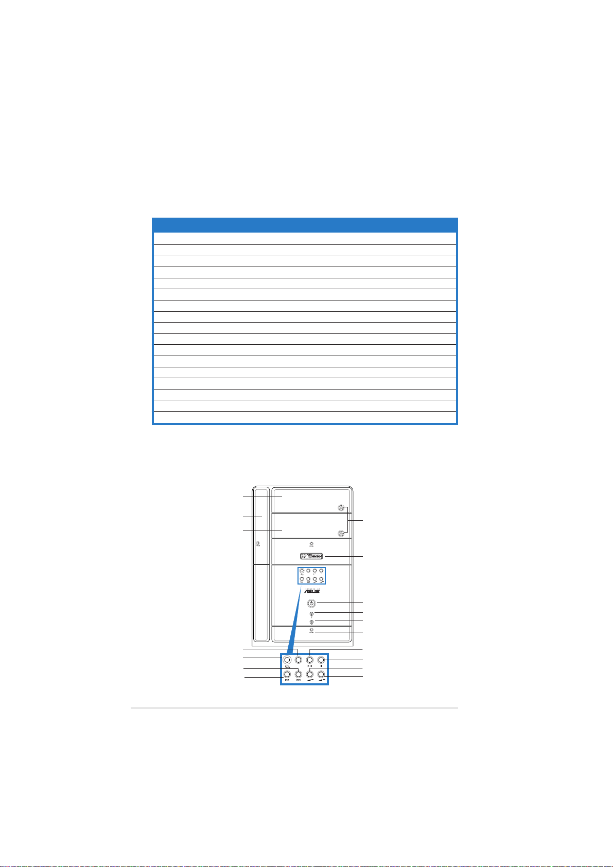
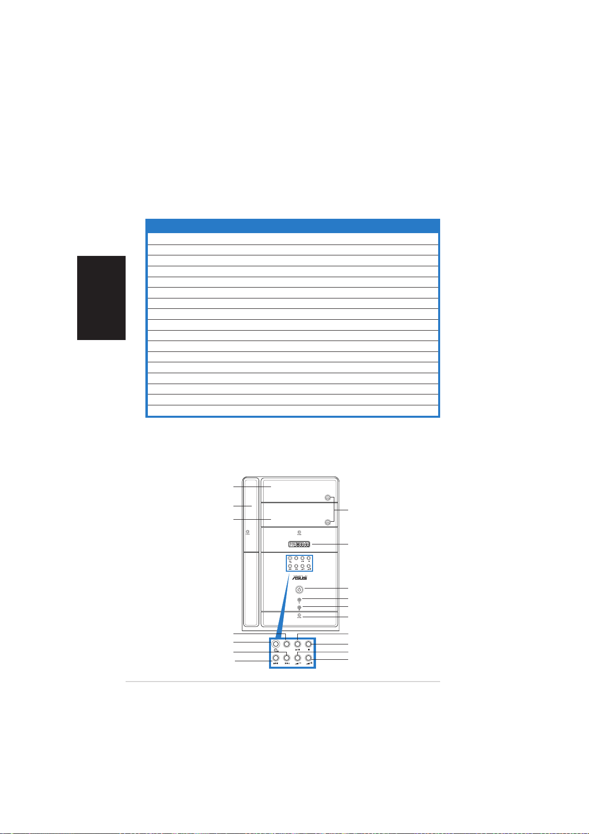
Front panel (external)
Front panel (external)Front panel (external)
Optical drive doorOptical drive door
Optical drive door
Optical drive doorOptical drive door
Floppy drive doorFloppy drive door
Floppy drive door
Floppy drive doorFloppy drive door
Second optical driveSecond optical drive
Second optical drive
Second optical driveSecond optical drive
Mode buttonMode button
Mode button
Mode buttonMode button
NEXT buttonNEXT button
NEXT button
NEXT buttonNEXT button
PREVIOUS buttonPREVIOUS button
PREVIOUS button
PREVIOUS buttonPREVIOUS button
iiii
ii
iiii
doordoor
door
doordoor
CD buttonCD button
CD button
CD buttonCD button
Eject buttonEject button
Eject button
Eject buttonEject button
LED panelLED panel
LED panel
LED panelLED panel
MODE
Power buttonPower button
Power button
Power buttonPower button
Power LEDPower LED
Power LED
Power LEDPower LED
HDD LEDHDD LED
HDD LED
HDD LEDHDD LED
Front panel I/O doorFront panel I/O door
Front panel I/O door
Front panel I/O doorFront panel I/O door
PLAY/PAUSE buttonPLAY/PAUSE button
PLAY/PAUSE button
PLAY/PAUSE buttonPLAY/PAUSE button
STOP buttonSTOP button
STOP button
MODE
STOP buttonSTOP button
Volume down buttonVolume down button
Volume down button
Volume down buttonVolume down button
Volume up buttonVolume up button
Volume up button
Volume up buttonVolume up button
Page 3
Front panel (internal)Front panel (internal)
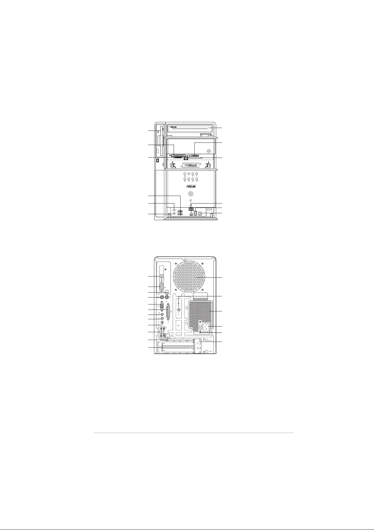
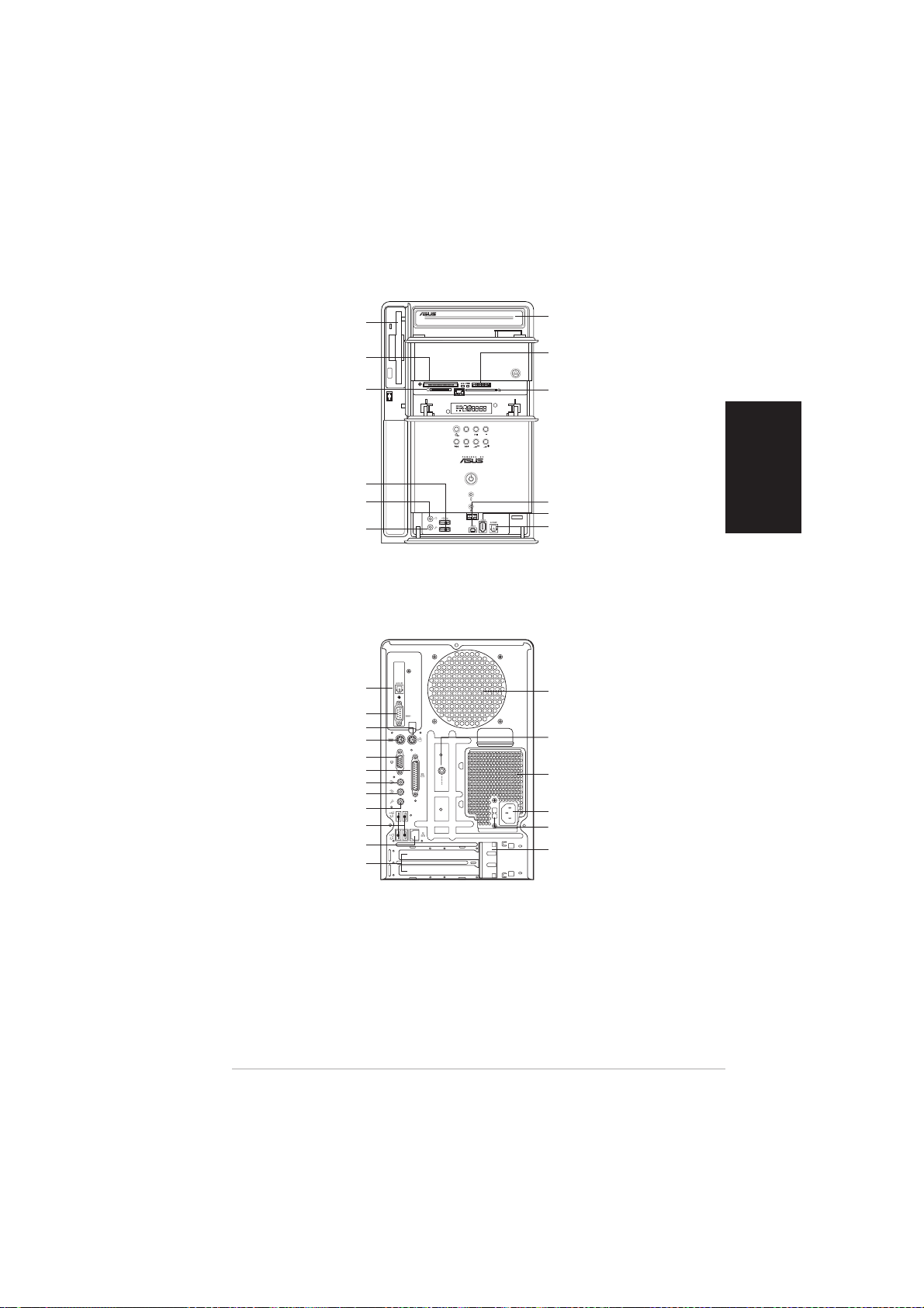
Front panel (internal)
Front panel (internal)Front panel (internal)
Floppy disk driveFloppy disk drive
Floppy disk drive
Floppy disk driveFloppy disk drive
®®
®
CompactFlashCompactFlash
CompactFlash
CompactFlashCompactFlash
Microdrive™ card slotMicrodrive™ card slot
Microdrive™ card slot
Microdrive™ card slotMicrodrive™ card slot
SmartMediaSmartMedia
SmartMedia
SmartMediaSmartMedia
Rear panelRear panel
Rear panel
Rear panelRear panel
Optical S/PDIF portOptical S/PDIF port
Optical S/PDIF port
Optical S/PDIF portOptical S/PDIF port
PS/2 keyboard portPS/2 keyboard port
PS/2 keyboard port
PS/2 keyboard portPS/2 keyboard port
®®
®
®®
USB 2.0 portsUSB 2.0 ports
USB 2.0 ports
USB 2.0 portsUSB 2.0 ports
Headphone portHeadphone port
Headphone port
Headphone portHeadphone port
Microphone portMicrophone port
Microphone port
Microphone portMicrophone port
Serial portSerial port
Serial port
Serial portSerial port
PS/2 mouse portPS/2 mouse port
PS/2 mouse port
PS/2 mouse portPS/2 mouse port
Parallel portParallel port
Parallel port
Parallel portParallel port
Line Out portLine Out port
Line Out port
Line Out portLine Out port
Line In portLine In port
Line In port
Line In portLine In port
Microphone portMicrophone port
Microphone port
Microphone portMicrophone port
USB 2.0 portsUSB 2.0 ports
USB 2.0 ports
USB 2.0 portsUSB 2.0 ports
LAN (RJ-45) portLAN (RJ-45) port
LAN (RJ-45) port
LAN (RJ-45) portLAN (RJ-45) port
Expansion slotExpansion slot
Expansion slot
Expansion slotExpansion slot
®®
//
/
//
card slot card slot
card slot
card slot card slot
VGA portVGA port
VGA port
VGA portVGA port
coverscovers
covers
coverscovers
Optical driveOptical drive
Optical drive
Optical driveOptical drive
(optional)(optional)
(optional)
(optional)(optional)
®®
®
MemoryStickMemoryStick
MemoryStick
MemoryStickMemoryStick
MemoryStick Pro™ cardMemoryStick Pro™ card
MemoryStick Pro™ card
MemoryStick Pro™ cardMemoryStick Pro™ card
slotslot
slot
slotslot
Secure DigitalSecure Digital
Secure Digital
Secure DigitalSecure Digital
MultimediaCard slotMultimediaCard slot
MultimediaCard slot
MultimediaCard slotMultimediaCard slot
MODE
4-pin IEEE 1394a port4-pin IEEE 1394a port
4-pin IEEE 1394a port
4-pin IEEE 1394a port4-pin IEEE 1394a port
6-pin IEEE 1394a port6-pin IEEE 1394a port
6-pin IEEE 1394a port
6-pin IEEE 1394a port6-pin IEEE 1394a port
S/PDIF In portS/PDIF In port
S/PDIF In port
S/PDIF In portS/PDIF In port
Chassis fan ventChassis fan vent
Chassis fan vent
Chassis fan ventChassis fan vent
Radio antenna portRadio antenna port
Radio antenna port
Radio antenna portRadio antenna port
Power supply unitPower supply unit
Power supply unit
Power supply unitPower supply unit
fan ventfan vent
fan vent
fan ventfan vent
Power connectorPower connector
Power connector
Power connectorPower connector
Voltage selectorVoltage selector
Voltage selector
Voltage selectorVoltage selector
Expansion card lockExpansion card lock
Expansion card lock
Expansion card lockExpansion card lock
®®
//
/
//
™™
™
™™
//
/
//
iiiiii
iii
iiiiii
Page 4
Installation
IMPORTANT! IMPORTANT!
IMPORTANT! Refer to the system user guide for installation details
IMPORTANT! IMPORTANT!
and other system information.
Removing the coverRemoving the cover
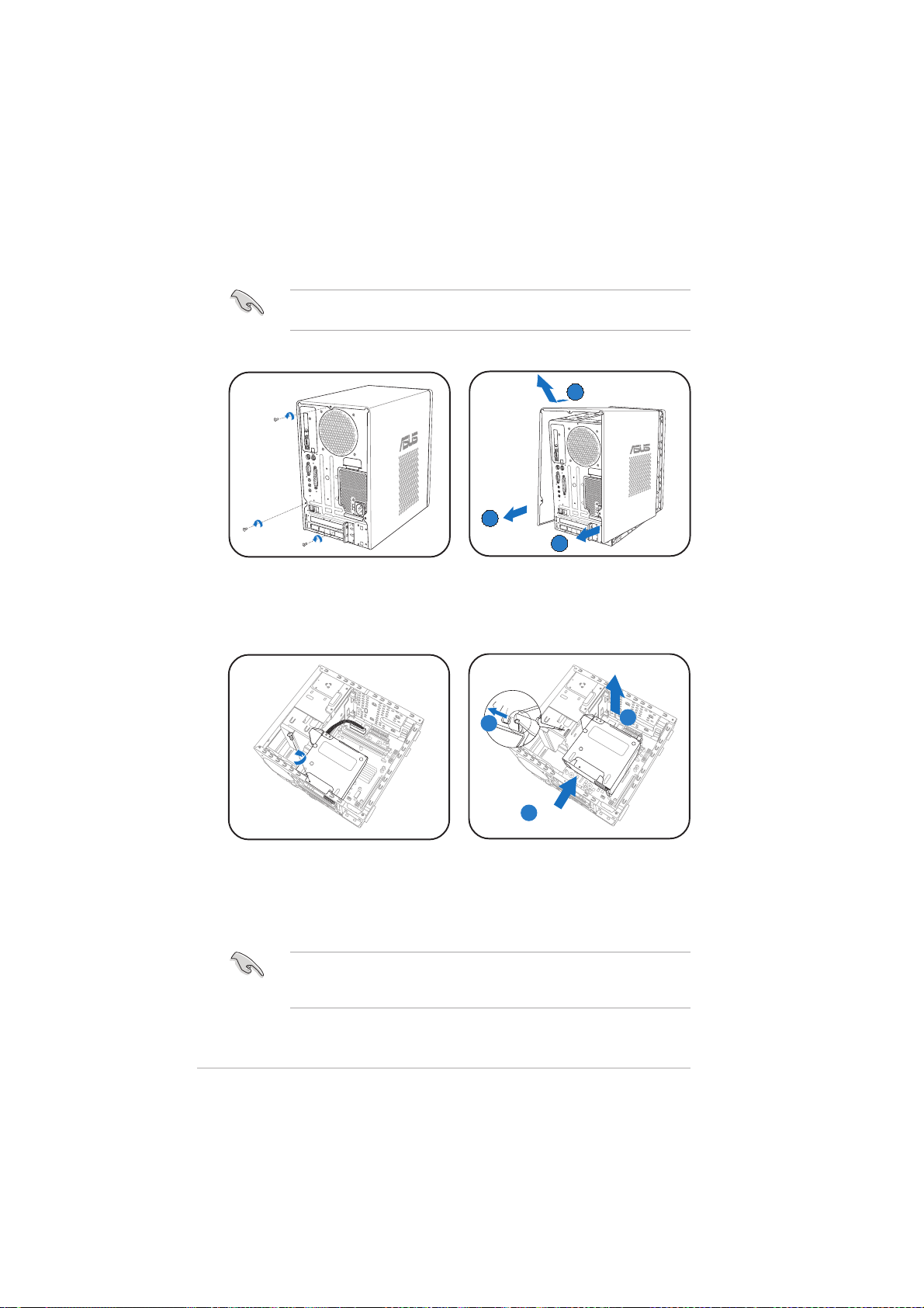
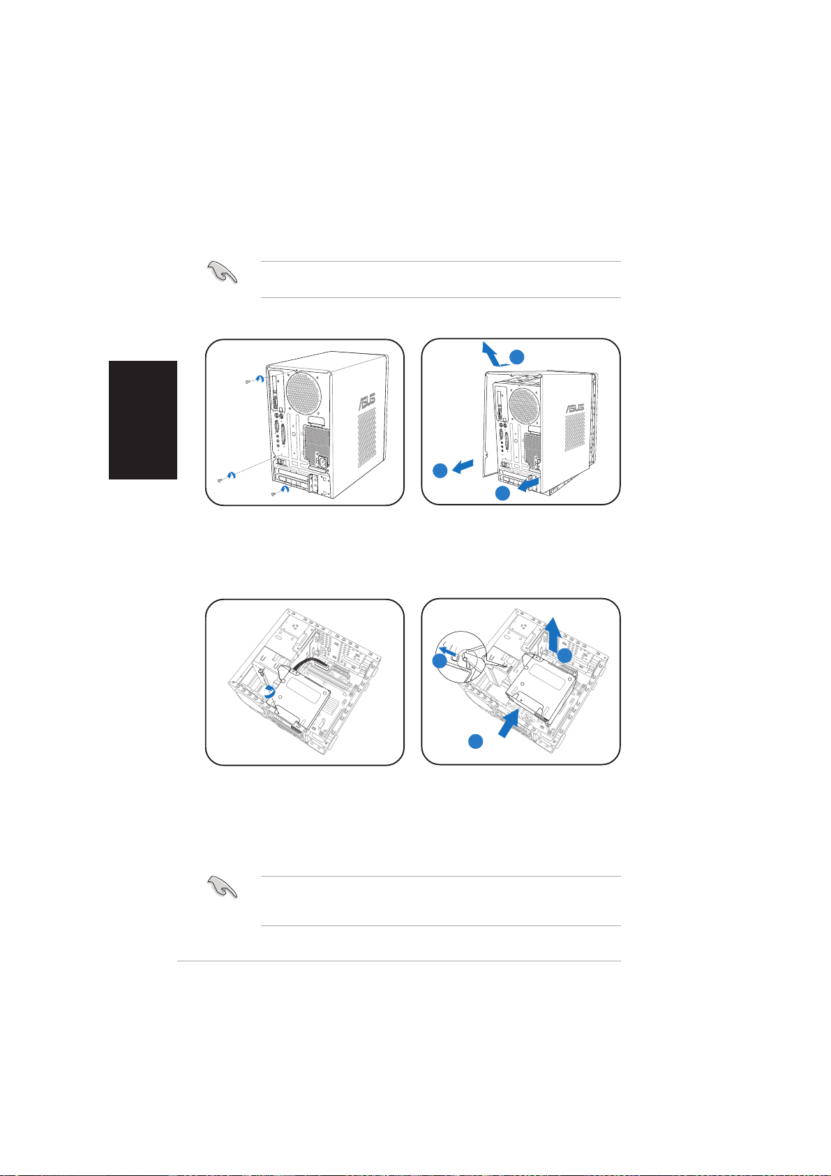
Removing the cover
Removing the coverRemoving the cover
BB
B
BB
AA
A
AA
AA
A
AA
1. Locate and remove three
cover screws.
Removing the power supply unitRemoving the power supply unit
Removing the power supply unit
Removing the power supply unitRemoving the power supply unit
1. Disconnect all power plugs
from the system components
and the motherboard, then
remove the PSU screw.
2. Pull the cover toward the rear
panel (A), then lift (B).
AA
A
AA
2. Slide the PSU to the left (A)
until the side hook is
disengaged. Push the PSU
toward the front panel (B),
then lift (C).
IMPORTANT! IMPORTANT!
IMPORTANT! When removing the PSU, make sure to hold or support it
IMPORTANT! IMPORTANT!
firmly. The unit might accidentally drop and damage the other system
components.
CC
C
CC
BB
B
BB
iviv
iv
iviv
Page 5
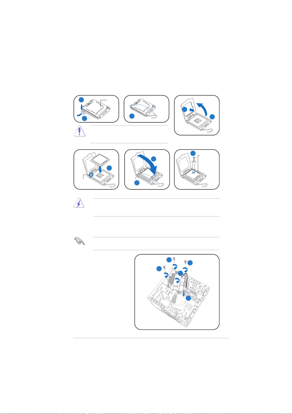
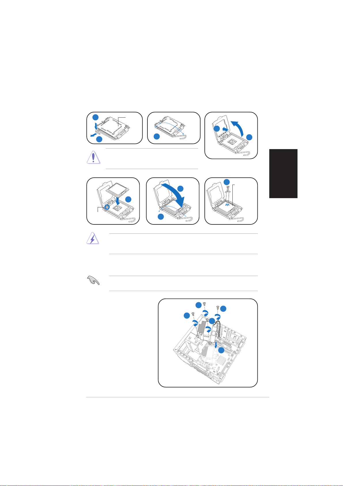
Installing the CPUInstalling the CPU
Installing the CPU
Installing the CPUInstalling the CPU
11
1
11
22
2
22
CAUTION. CAUTION.
CAUTION. To prevent damage to the
CAUTION. CAUTION.
PnPPnP
PnP
PnPPnP
capcap
cap
capcap
44
4
44
33
3
33
socket pins, do not remove the PnP cap
unless you are installing a CPU.
88
8
88
ApplyApply
Apply
ApplyApply
ThermalThermal
Thermal
ThermalThermal
InterfaceInterface
Interface
InterfaceInterface
MaterialMaterial
Material
MaterialMaterial
AlignmentAlignment
Alignment
AlignmentAlignment
keykey
key
keykey
WARNING! DO NOT WARNING! DO NOT
WARNING! DO NOT eat the Thermal Interface Material. If it gets into
WARNING! DO NOT WARNING! DO NOT
77
7
77
66
6
66
88
8
88
your eyes or touches your skin, make sure to wash it off immediately,
and seek professional medical help.
Installing the CPU fan and heatsink assemblyInstalling the CPU fan and heatsink assembly
Installing the CPU fan and heatsink assembly
Installing the CPU fan and heatsink assemblyInstalling the CPU fan and heatsink assembly
Make sure to turn off your computer and unplug the cable from the
power source before installing the CPU fan and heatsink assembly.
55
5
55
1. Position the CPU fan and
heatsink assembly on
top of the installed CPU.
2. Drive in four screws into
the CPU fan screw
holes.
3. Connect the CPU fan
cable to the connector
on the motherboard.
22
2
22
22
2
22
22
2
22
22
2
22
33
3
33
vv
v
vv
Page 6
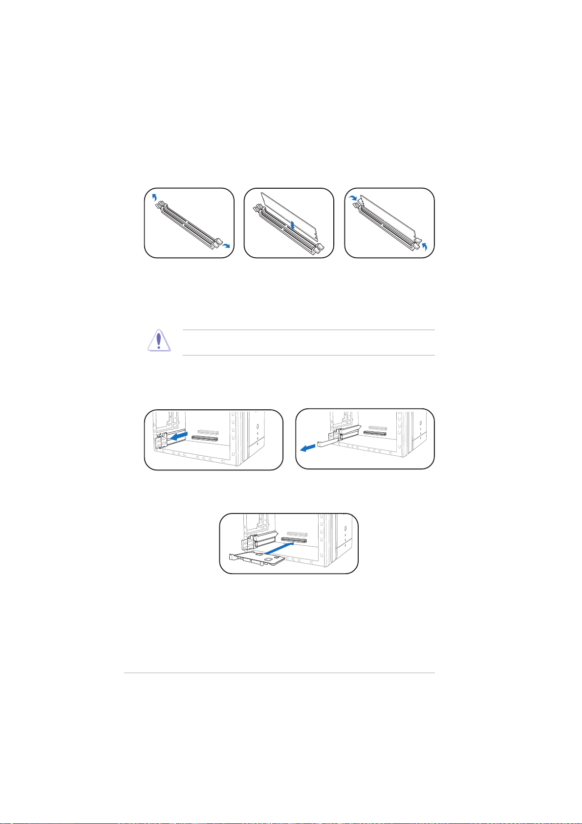
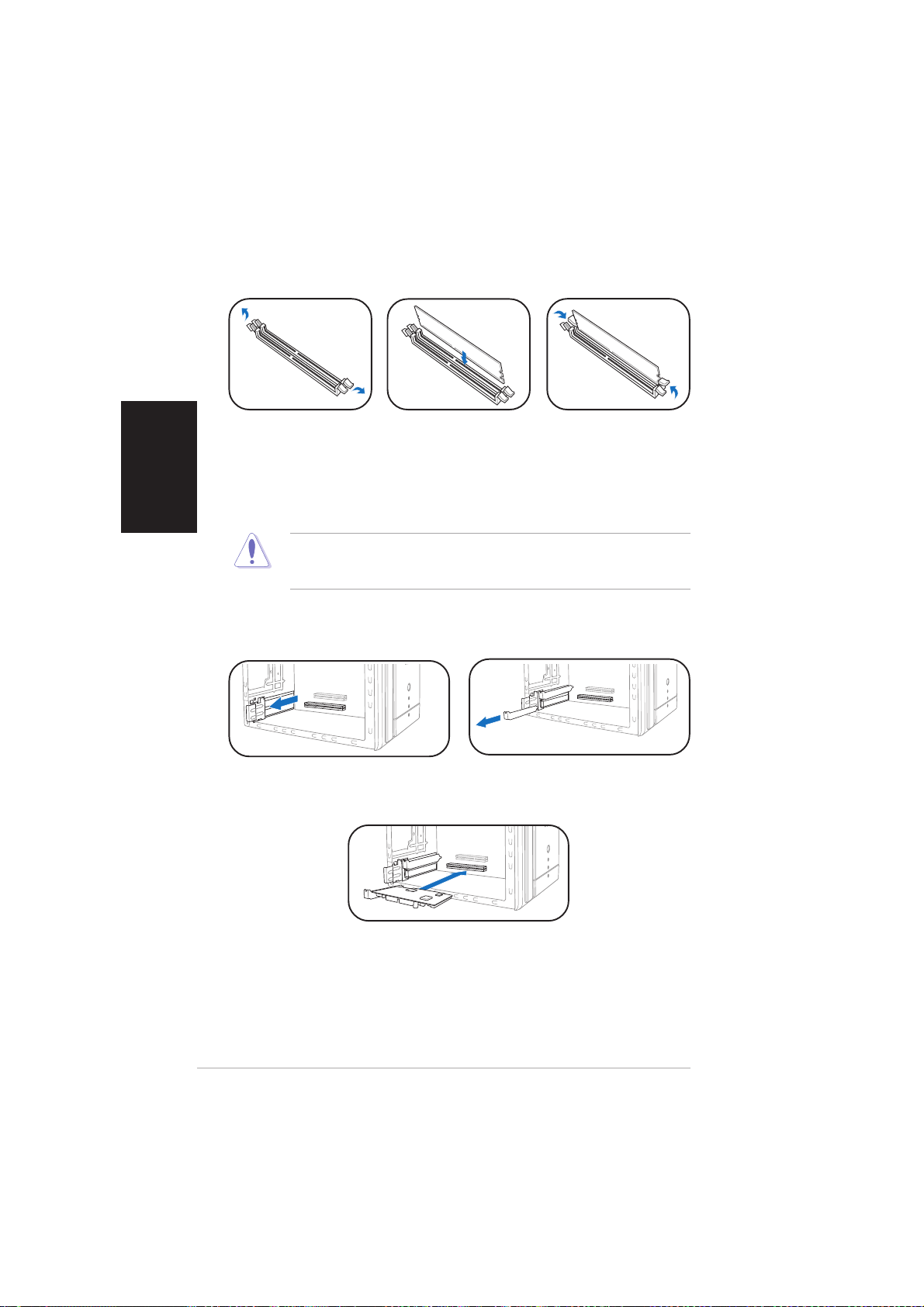
Installing memory module(s)Installing memory module(s)
Installing memory module(s)
Installing memory module(s)Installing memory module(s)
1. Press the
retaining clips of
the DIMM socket
outward.
CAUTION! CAUTION!
CAUTION! A DDR DIMM is keyed with a notch so that it fits in only one
CAUTION! CAUTION!
direction. Do not force a DIMM into a socket to avoid damaging the DIMM!
Installing expansion cardsInstalling expansion cards
Installing expansion cards
Installing expansion cardsInstalling expansion cards
1. Pull the expansion card lock to
the direction of the arrow.
2. Align a DIMM on
the socket.
3. Insert the DIMM
firmly to the
socket until the
retaining clips snap
back in place.
2. Remove the metal bracket
opposite the slot you intend to
use.
vivi
vi
vivi
3. Align the card connector
with the slot, then press
firmly.
Page 7
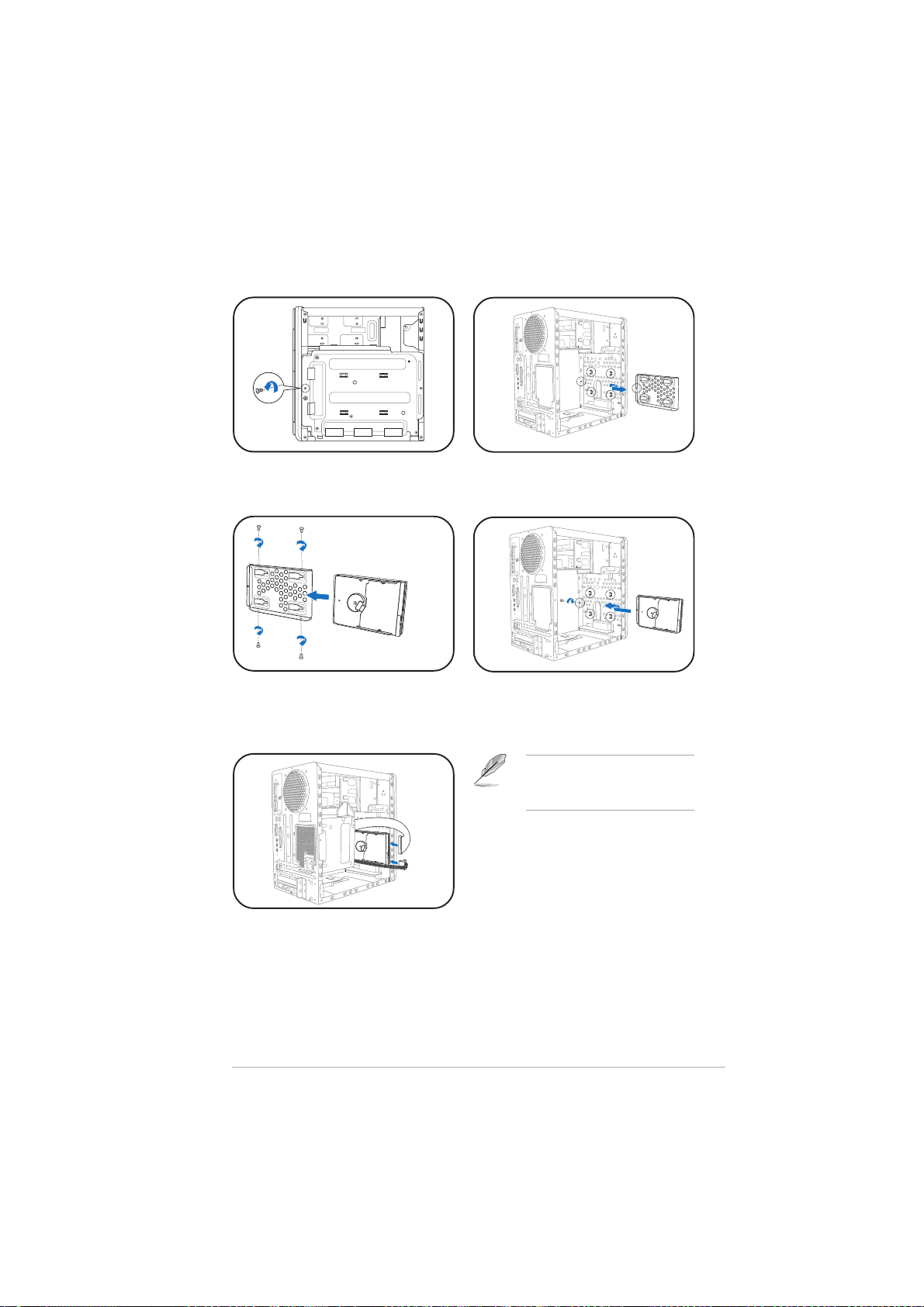
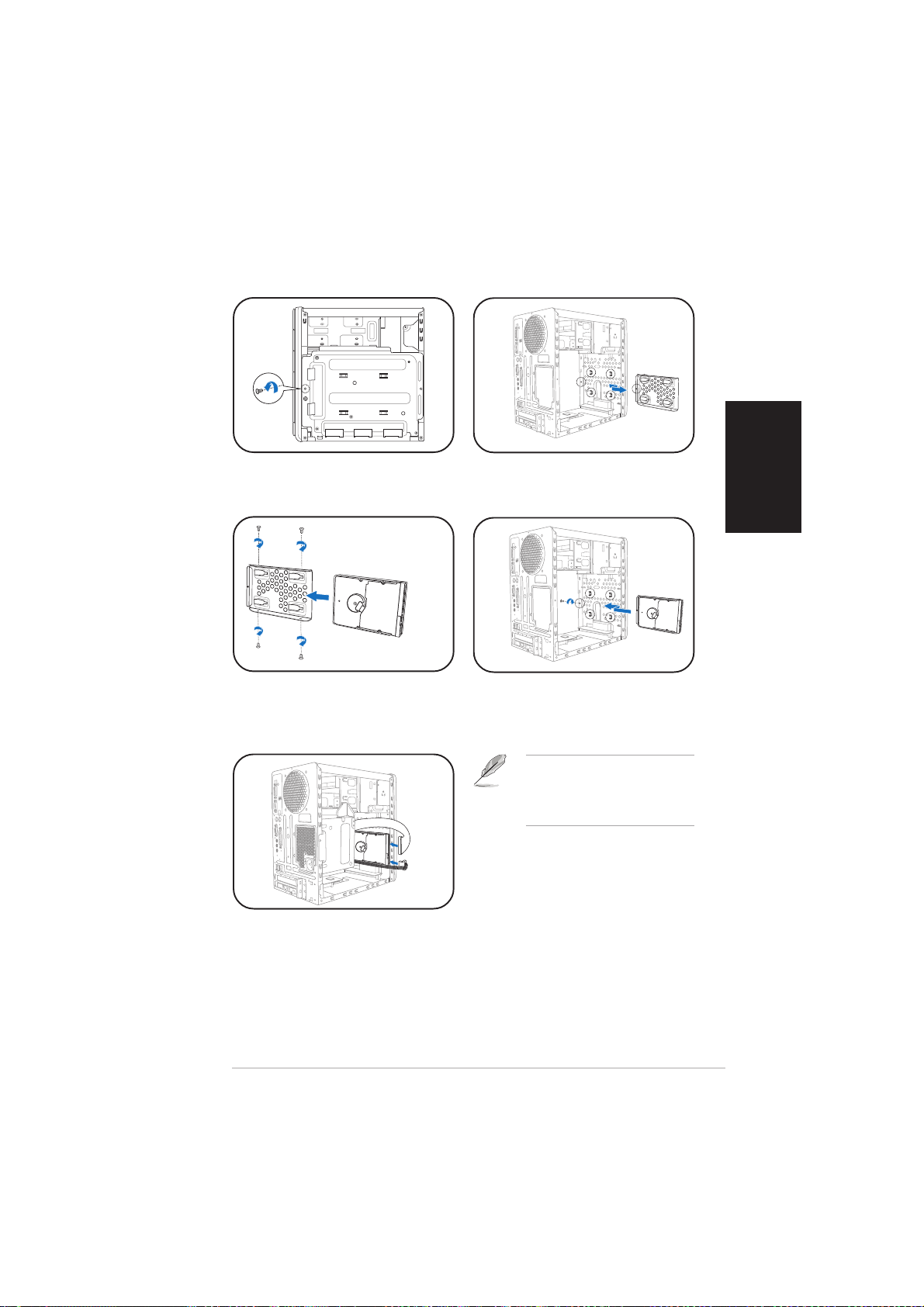
Installing a hard disk driveInstalling a hard disk drive
Installing a hard disk drive
Installing a hard disk driveInstalling a hard disk drive
1. Remove the HDD tray lock
screw.
3. Place a hard disk drive on the
tray, then secure it with four
screws.
2. Slide the HDD tray outward.
4. Reinstall the HDD tray inside
the chassis, then secure the
HDD tray with the lock screw.
NOTE. NOTE.
NOTE. Refer to the User
NOTE. NOTE.
Guide for details on installing a
Serial ATA HDD.
5. Connect the power and signal
cables to the connectors at
the back of the drive.
viivii
vii
viivii
Page 8
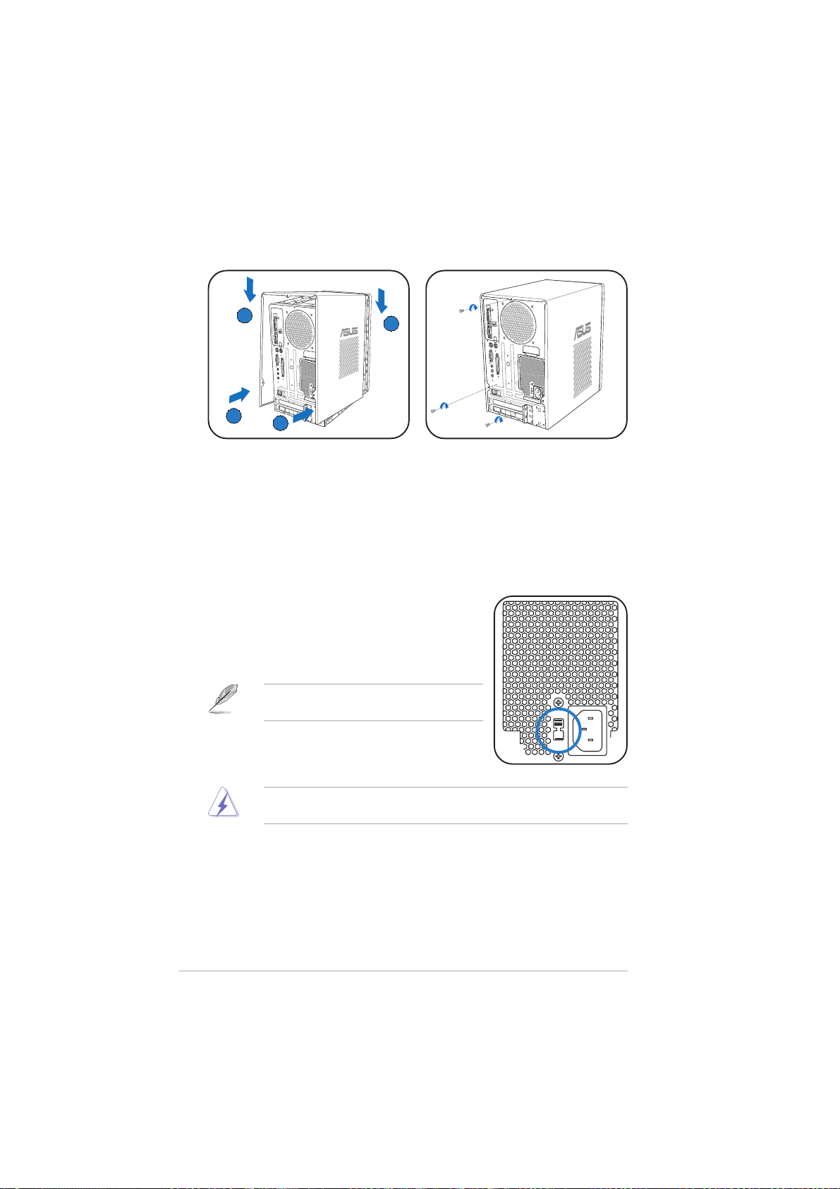
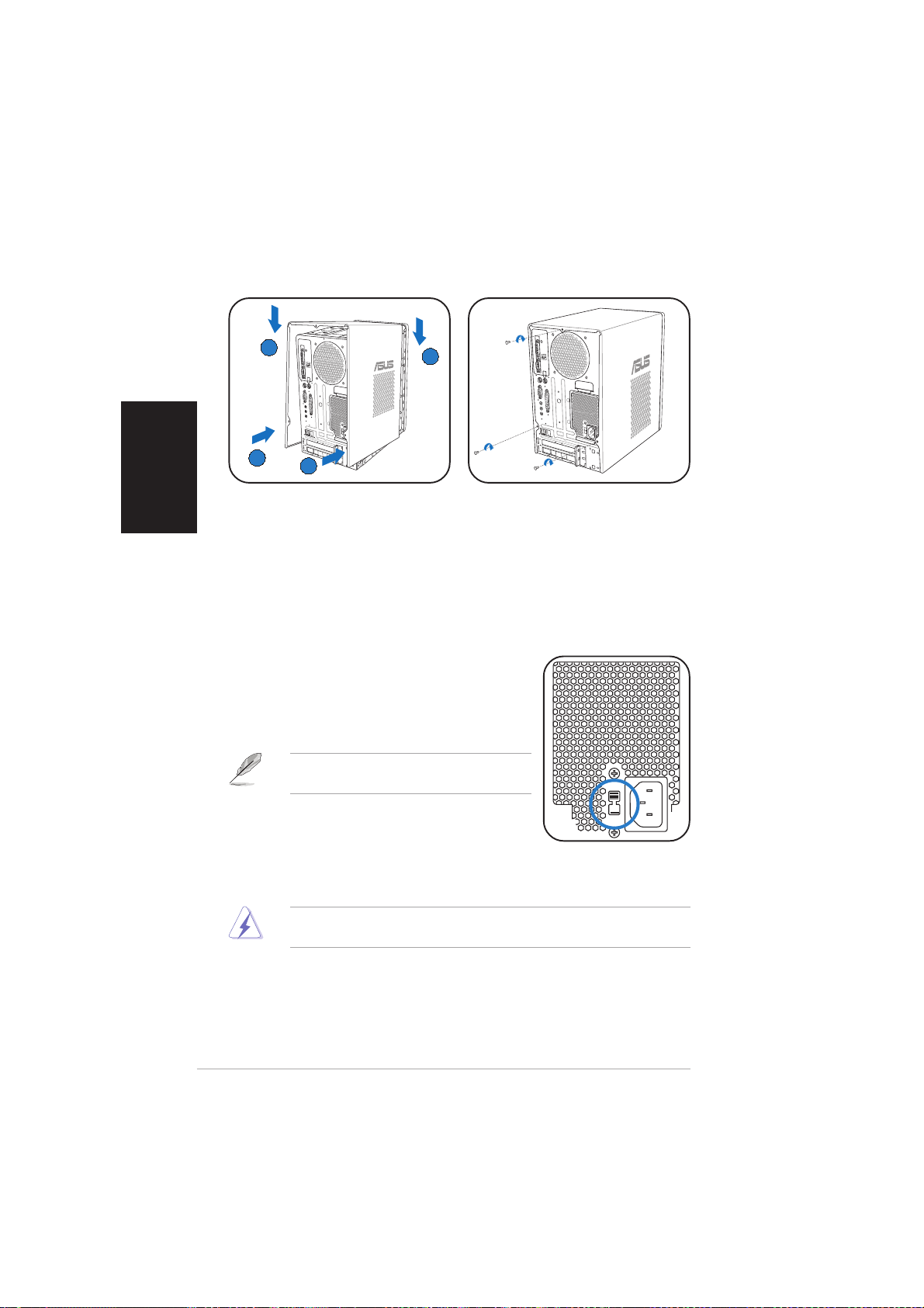
Replacing the coverReplacing the cover
Replacing the cover
Replacing the coverReplacing the cover
BB
B
BB
AA
A
AA
AA
A
AA
BB
B
BB
1. Fit the cover tabs with the
chassis rail and the front panel
2. Secure the cover with three
screws.
tabs (A), then lower the rear
edge of the cover as shown
(B).
Selecting the voltage
The PSU has a 115 V/230 V voltage selector
switch located beside the power connector. Use
this switch to select the appropriate system
input voltage according to the voltage supply in
your area.
NOTE.NOTE.
NOTE. The voltage selector is set to
NOTE.NOTE.
230 V by default.
If the voltage supply in your area is 100-127 V,
set the switch to 115 V. If the voltage supply in
your area is 200-240 V, set the switch to 230 V.
WARNING! WARNING!
WARNING! Setting the switch to 115 V in a 230 V environment will
WARNING! WARNING!
seriously damage the system!
viiiviii
viii
viiiviii
Page 9
®
T2-PH2
MODE
Système barebone
Guide d’installation rapide
Français
Copyright © 2006 ASUSTeK COMPUTER INC. Tous droits réservés.Copyright © 2006 ASUSTeK COMPUTER INC. Tous droits réservés.
Copyright © 2006 ASUSTeK COMPUTER INC. Tous droits réservés.
Copyright © 2006 ASUSTeK COMPUTER INC. Tous droits réservés.Copyright © 2006 ASUSTeK COMPUTER INC. Tous droits réservés.
Page 10
Français
Contenu du carton
Vérifiez que les éléments suivants accompagnent bien votre T2-PH2.
Contactez votre revendeur immédiatement si l’un d’entre eux était
manquant ou endommagé.
Description des élémentsDescription des éléments
Description des éléments
Description des élémentsDescription des éléments
1.1.
Système barebone ASUS T2-PH2 Système barebone ASUS T2-PH2
1.
Système barebone ASUS T2-PH2 avec
1.1.
Système barebone ASUS T2-PH2 Système barebone ASUS T2-PH2
•
Carte mère ASUS
•
Alimentation 250 W PFC
•
Port Gigabit LAN
•
Assemblage dissipateur/ventilateur pour CPU•Lecteur de cartes 7-en-1
•
2 x baies 5.25”
•
1 x baie pour lecteur de disquettes 3.5”•1 x baie pour disque dur 3.5”
•
Panneau de LED
2.2.
CâblesCâbles
2.
Câbles
2.2.
CâblesCâbles
•
Câble d’alimentation
•
Câble Serial ATA
•
Câble d’alimentation Serial ATA
3.3.
CD de supportCD de support
3.
CD de support
3.3.
CD de supportCD de support
4.4.
ManuelManuel
4.
Manuel
4.4.
ManuelManuel
5.5.
Eléments optionnelsEléments optionnels
5.
Eléments optionnels
5.5.
Eléments optionnelsEléments optionnels
•
Lecteur optique
•
Lecteur de disquettes
(CD-ROM/CD-RW/DVD-ROM/DVD-RW)
•
6 x ports USB 2.0
•
2 x ports IEEE 1394a
•
Port S/PDIF
•
Module radio FM et antenne
•
Boutons de lecture Audio DJ
Caractéristiques
Façade (externe)
Trappe du lecteur optiqueTrappe du lecteur optique
Trappe du lecteur optique
Trappe du lecteur optiqueTrappe du lecteur optique
Trappe du lecteur deTrappe du lecteur de
Trappe du lecteur de
Trappe du lecteur deTrappe du lecteur de
Seconde trappe deSeconde trappe de
Seconde trappe de
Seconde trappe deSeconde trappe de
Bouton PRECEDENTBouton PRECEDENT
Bouton PRECEDENT
Bouton PRECEDENTBouton PRECEDENT
iiii
ii
iiii
disquettesdisquettes
disquettes
disquettesdisquettes
lecteur optiquelecteur optique
lecteur optique
lecteur optiquelecteur optique
Bouton ModeBouton Mode
Bouton Mode
Bouton ModeBouton Mode
Bouton CDBouton CD
Bouton CD
Bouton CDBouton CD
Bouton SUIVANTBouton SUIVANT
Bouton SUIVANT
Bouton SUIVANTBouton SUIVANT
Bouton d’éjectionBouton d’éjection
Bouton d’éjection
Bouton d’éjectionBouton d’éjection
LEDsLEDs
LEDs
LEDsLEDs
MODE
Bouton d’alimentationBouton d’alimentation
Bouton d’alimentation
Bouton d’alimentationBouton d’alimentation
LED d’alimentationLED d’alimentation
LED d’alimentation
LED d’alimentationLED d’alimentation
LED du disque durLED du disque dur
LED du disque dur
LED du disque durLED du disque dur
Trappe d’E/S en façadeTrappe d’E/S en façade
Trappe d’E/S en façade
Trappe d’E/S en façadeTrappe d’E/S en façade
Bouton PLAY/PAUSEBouton PLAY/PAUSE
Bouton PLAY/PAUSE
Bouton PLAY/PAUSEBouton PLAY/PAUSE
Bouton STOPBouton STOP
Bouton STOP
MODE
Bouton STOPBouton STOP
Bouton baisse du volumeBouton baisse du volume
Bouton baisse du volume
Bouton baisse du volumeBouton baisse du volume
Bouton hausse du volumeBouton hausse du volume
Bouton hausse du volume
Bouton hausse du volumeBouton hausse du volume
Page 11
Façade (interne)Façade (interne)
Façade (interne)
Façade (interne)Façade (interne)
Lecteur de disquettesLecteur de disquettes
Lecteur de disquettes
Lecteur de disquettesLecteur de disquettes
®®
®
CompactFlashCompactFlash
CompactFlash
CompactFlashCompactFlash
Microdrive™ card slotMicrodrive™ card slot
Microdrive™ card slot
Microdrive™ card slotMicrodrive™ card slot
SmartMediaSmartMedia
SmartMedia
SmartMediaSmartMedia
ArrièreArrière
Arrière
ArrièreArrière
Port S/PDIF optiquePort S/PDIF optique
Port S/PDIF optique
Port S/PDIF optiquePort S/PDIF optique
®®
®
®®
Ports USB 2.0Ports USB 2.0
Ports USB 2.0
Ports USB 2.0Ports USB 2.0
Port CasquePort Casque
Port Casque
Port CasquePort Casque
Port MicrophonePort Microphone
Port Microphone
Port MicrophonePort Microphone
Port SériePort Série
Port Série
Port SériePort Série
Port souris PS/2Port souris PS/2
Port souris PS/2
Port souris PS/2Port souris PS/2
Port clavier PS/2Port clavier PS/2
Port clavier PS/2
Port clavier PS/2Port clavier PS/2
Port ParallèlePort Parallèle
Port Parallèle
Port ParallèlePort Parallèle
Port Line OutPort Line Out
Port Line Out
Port Line OutPort Line Out
Port Line InPort Line In
Port Line In
Port Line InPort Line In
Port MicrophonePort Microphone
Port Microphone
Port MicrophonePort Microphone
Ports USB 2.0Ports USB 2.0
Ports USB 2.0
Ports USB 2.0Ports USB 2.0
Port LAN (RJ-45)Port LAN (RJ-45)
Port LAN (RJ-45)
Port LAN (RJ-45)Port LAN (RJ-45)
Couverture desCouverture des
Couverture des
Couverture desCouverture des
slots d’extensionslots d’extension
slots d’extension
slots d’extensionslots d’extension
®®
//
/
//
card slot card slot
card slot
card slot card slot
Port VGAPort VGA
Port VGA
Port VGAPort VGA
Lecteur optiqueLecteur optique
Lecteur optique
Lecteur optiqueLecteur optique
(optionnel)(optionnel)
(optionnel)
(optionnel)(optionnel)
Slot pour cartesSlot pour cartes
Slot pour cartes
Slot pour cartesSlot pour cartes
MemoryStickMemoryStick
MemoryStick
MemoryStickMemoryStick
MemoryStick Pro™MemoryStick Pro™
MemoryStick Pro™
MemoryStick Pro™MemoryStick Pro™
Slot Secure DigitalSlot Secure Digital
Slot Secure Digital
Slot Secure DigitalSlot Secure Digital
MultimediaCardMultimediaCard
MultimediaCard
MultimediaCardMultimediaCard
MODE
Port IEEE 1394a 4 brochesPort IEEE 1394a 4 broches
Port IEEE 1394a 4 broches
Port IEEE 1394a 4 brochesPort IEEE 1394a 4 broches
Port IEEE 1394a 6 brochesPort IEEE 1394a 6 broches
Port IEEE 1394a 6 broches
Port IEEE 1394a 6 brochesPort IEEE 1394a 6 broches
Port S/PDIF inPort S/PDIF in
Port S/PDIF in
Port S/PDIF inPort S/PDIF in
Ventilation châssisVentilation châssis
Ventilation châssis
Ventilation châssisVentilation châssis
Port antenne radioPort antenne radio
Port antenne radio
Port antenne radioPort antenne radio
VentilationVentilation
Ventilation
VentilationVentilation
alimentationalimentation
alimentation
alimentationalimentation
Connecteur d’alimentaitonConnecteur d’alimentaiton
Connecteur d’alimentaiton
Connecteur d’alimentaitonConnecteur d’alimentaiton
Sélecteur de tensionsSélecteur de tensions
Sélecteur de tensions
Sélecteur de tensionsSélecteur de tensions
Verrou des cartesVerrou des cartes
Verrou des cartes
Verrou des cartesVerrou des cartes
d’extensiond’extension
d’extension
d’extensiond’extension
®®
®
®®
//
/
//
™™
™
™™
//
/
//
Français
iiiiii
iii
iiiiii
Page 12
Français
Installation
IMPORTANT ! IMPORTANT !
IMPORTANT ! reportez-vous au manuel pour plus de détails
IMPORTANT ! IMPORTANT !
d’installation et autres informations système.
Ouvrir le châssisOuvrir le châssis
Ouvrir le châssis
Ouvrir le châssisOuvrir le châssis
BB
B
BB
AA
A
AA
AA
A
AA
1. Localisez et dévissez les trois
vis de châssis.
Enlever l’alimentationEnlever l’alimentation
Enlever l’alimentation
Enlever l’alimentationEnlever l’alimentation
1. Déconnectez toutes les prises
d’alimentaiton du système et
des composants puis enlevez
la vis de l’alimentation.
IMPORTANT ! IMPORTANT !
IMPORTANT ! lorsque vous enlevez l’alimentation assurez-vous de
IMPORTANT ! IMPORTANT !
bien la tenir car elle pourrait tomber et endommager les autres
composants du système.
2. Tirez vers l’arrière (A), puis
levez (B).
CC
C
AA
A
AA
BB
B
BB
CC
2. Glissez l’alimentation vers la
gauche (A) jusqu’à ce que les
crochets soient désengagés.
Poussez l’alimentation vers la
façade (B), puis soulevez (C).
iviv
iv
iviv
Page 13
Installer le CPUInstaller le CPU
Installer le CPU
Installer le CPUInstaller le CPU
11
1
11
22
2
22
ATTENTION. ATTENTION.
ATTENTION. pour éviter d’endommager les
ATTENTION. ATTENTION.
plaqueplaque
plaque
plaqueplaque
PnPPnP
PnP
PnPPnP
44
4
44
33
3
33
broches du socket, n’enlevez la plaque PnP
que pour installer un CPU.
88
8
88
Mettz deMettz de
Mettz de
Mettz deMettz de
la pâtela pâte
la pâte
la pâtela pâte
thermiquethermique
thermique
thermiquethermique
ClefClef
Clef
ClefClef
d’alignementd’alignement
d’alignement
d’alignementd’alignement
ATTENTION ! NE MANGEZ PAS ATTENTION ! NE MANGEZ PAS
ATTENTION ! NE MANGEZ PAS la pâte thermique. Si vous vous en
ATTENTION ! NE MANGEZ PAS ATTENTION ! NE MANGEZ PAS
77
7
77
66
6
66
88
8
88
mettez dans les yeux ou sur votre peau, lavez-la à grande eau
immédiatement et allez voir un médecin.
Installer le système de refroidissement du CPUInstaller le système de refroidissement du CPU
Installer le système de refroidissement du CPU
Installer le système de refroidissement du CPUInstaller le système de refroidissement du CPU
Assurez-vous d’éteindre l’ordinateur et de débrancher le câble
d’alimentation avant d’installer l’ensemble dissipateur/ventilateur.
55
5
55
Français
1. Positionnez l’ensemble
dissipateur/ventilateur
sur le CPU installé.
2. Vissez quatre vis dans
les pas de vis du
ventilateur
3. Connectez le câble du
ventilateur au
connecteur de la carte
mère.
22
2
22
22
2
22
22
2
22
22
2
22
33
3
33
vv
v
vv
Page 14
Installer des modules de mémoireInstaller des modules de mémoire
Installer des modules de mémoire
Installer des modules de mémoireInstaller des modules de mémoire
Français
1. Pressez les clips
de rétention des
sockets DIMM
vers l’extérieur.
ATTENTION ATTENTION
ATTENTION
ATTENTION ATTENTION
sorte qu’il ne puisse entrer que dans un seul sens. Ne forcez pas
inutilement sur un module pour ne pas l’endommager.
Installer les cartes d’extensionInstaller les cartes d’extension
Installer les cartes d’extension
Installer les cartes d’extensionInstaller les cartes d’extension
1. Tirez le verrou des cartes
d’extension dans le sens de la
flèche.
2. Alignez un module
sur le socket.
! !
! Un module DIMM DDR est verrouillé par une encoche de
! !
2. Enlevez la protection
métallique du slot que vous
voulez utiliser.
3. Insérez le module
DIMM dans le
socket jusqu’à ce
que lec clips
reviennent en
place.
vivi
vi
vivi
3. Positionnez le connecteur de
la carte sur le slot, puis
pressez fermement.
Page 15
Installer un disque durInstaller un disque dur
Installer un disque dur
Installer un disque durInstaller un disque dur
1. Dévissez le plateau du disque
dur.
3. Placez le disque dur sur le
plateau puis fixez-le avec
quatre vis.
2. Sortez le plateau.
4. Reinstallez le plateau du
disque dur dans le châssis puis
remettez la vis de fixation.
NOTE. NOTE.
NOTE. reportez-vous au
NOTE. NOTE.
manuel pour plus de détails sur
l’installation d’un disque dur
Serial ATA.
Français
5. Connectez les câbles de signal
et d’alimentation aux prises à
l’arrière du disque.
viivii
vii
viivii
Page 16
Français
Refermer le châssisRefermer le châssis
Refermer le châssis
Refermer le châssisRefermer le châssis
BB
B
BB
AA
A
AA
AA
A
AA
BB
B
BB
1. Alignez les onglets du capot
2. Fixez le capot avec trois vis.
avec le rail du châssis et les
onglets de la façade (A), puis
baissez le bord arrière comme
indiqué (B).
Choisir le voltage
L’alimentation est équipée d’un sélecteur de
tension 115 V/230 V situé près du connecteur
d’alimentation. Utilisez cet interrupteur pour
choisir la tension d’entrée appropriée à votre
région.
NOTE.NOTE.
NOTE. le sélecteur de tension est placé
NOTE.NOTE.
sur 230 V par défaut.
Si la tension dans votre région est de 100-127
V, passez l’interrupteur sur 115 V. Si la tension
dans votre région est de 200-240 V, passez l’interrupteur sur 230 V.
ATTENTION ! ATTENTION !
ATTENTION ! Paser l’interrupteur sur 115 V dans une région à 230 V
ATTENTION ! ATTENTION !
endommagera gravement le système !
viiiviii
viii
viiiviii
Page 17
®
MODE
T2-PH2
Copyright 2006 ASUSTeK COMPUTER INC. All Rights Reserved.
Page 18

1. T2-PH2
6 USB 2.0
250 W PFC 2 IEEE 1394a
Gigabit LAN S/PDIF
CPU 7-in-1
2 x 5.25 FM
1 x 3.5 1 x 3.5
LED Audio DJ
2.
Serial ATA
Serial ATA
3.
4.
5.
(CD-ROM/CD-RW/DVD-ROM/DVD-RW)
( )
LED
MODE
I/O
CD
iiii
ii
iiii
MODE
/
Page 19

( )
( )
CompactFlash Microdrive
SmartMedia
USB 2.0
S/PDIF
PS/2
PS/2
VGA
MemoryStick MemoryStick
Pro
Secure Digital
MultimediaCard
MODE
4-pin IEEE 1394a
6-pin IEEE 1394a
S/PDIF IN
USB 2.0
LAN (RJ-45)
iiiiii
iii
iiiiii
Page 20

!
B
A
A
1.
2. (A)
(B)
A
B
C
1. 2. 5.25
(A)
!
(B)
(C)
iviv
iv
iviv
Page 21

CPU
1
2
CPU
4
3
8
7
6
5
Alignment
key
CPU
CPU
1. CPU CPU
2.
3.
CPU_FAN
8
2
2
2
2
3
vv
v
vv
Page 22

1.
2. 3.
DDR DIMM
1. 2.
vivi
vi
vivi
3.
Page 23

1. 2.
3. 4.
Serial ATA
5.
viivii
vii
viivii
Page 24

B
B
A
1.
A
2.
230 V
100-127V
115V 200-240V
230V
! 230V 115V
viiiviii
viii
viiiviii
Page 25

®
MODE
T2-PH2
Copyright 2006 ASUSTeK COMPUTER INC. All Rights Reserved.
Page 26

1. T2-PH2
250 W PFC 2 IEEE 1394a
Gigabit LAN S/PDIF
CPU 7-in-1
2 x 5.25 FM
1 x 3.5 1 x 3.5
LED Audio DJ
2.
Serial ATA
Serial ATA
3.
4.
5.
(CD-ROM/CD-RW/DVD-ROM/DVD-RW)
( )
6 USB 2.0
LED
MODE
I/O
CD
iiii
ii
iiii
MODE
/
Page 27

( )
( )
CompactFlash Microdrive
SmartMedia
USB 2.0
S/PDIF
PS/2
PS/2
VGA
MemoryStick MemoryStick
Pro
Secure Digital
MultimediaCard
MODE
4-pin IEEE 1394a
6-pin IEEE 1394a
S/PDIF IN
USB 2.0
LAN (RJ-45)
iiiiii
iii
iiiiii
Page 28

!
B
A
A
1.
2. (A)
(B)
A
B
1. 2. 5.25
(A)
(C)
!
C
(B)
iviv
iv
iviv
Page 29

CPU
1
2
CPU
4
3
8
7
6
5
Alignment
key
CPU
CPU
1. CPU CPU
2.
3.
CPU_FAN
8
2
2
2
2
3
vv
v
vv
Page 30

1.
2. 3.
DDR DIMM
1. 2.
vivi
vi
vivi
3.
Page 31

1. 2.
3. 4.
Serial ATA
5.
viivii
vii
viivii
Page 32

B
B
A
1.
A
2.
230 V
100-127V
115V 200-240V
230V
! 230V 115V
viiiviii
viii
viiiviii
Page 33

®
T2-PH2
MODE
©©
©
©©
Page 34

• •
• •
• •
• •
• •
• •
• •
•
•
•
•
•
MODE
MODE
iiii
ii
iiii
Page 35

®®
®
®®
®
®®
™™
™
™™
®®
®
®®
MODE
®®
™™
™
™™
™™
™
™™
iiiiii
iii
iiiiii
Page 36

BB
B
BB
AA
A
AA
AA
A
AA
CC
C
AA
A
AA
BB
B
BB
CC
iviv
iv
iviv
Page 37

11
1
11
44
4
44
33
3
22
2
22
66
6
66
33
88
8
88
77
7
77
88
8
88
55
5
55
22
2
22
22
2
22
22
2
22
22
2
22
33
3
33
vv
v
vv
Page 38

vivi
vi
vivi
Page 39

viivii
vii
viivii
Page 40

BB
B
BB
AA
A
AA
AA
A
AA
BB
B
BB
viiiviii
viii
viiiviii
Page 41

한국어
®
T2-PH2
베어본 시스템
Quick 설치 가이드
Copyright © 2006 ASUSTeK COMPUTER INC. All Rights Reserved.
MODE
Page 42

ii
한국어한국어한국어
시스템 구성 품목
T2-PH2 시스템 구성 품목이 모두 포함되어 있는지 확인해 주십시오. 만약 구성 품
목이 빠져 있거나 손상되었다면 즉시 구입처에 문의해 주십시오.
제품 사양
전면부 패널(외부)
구성품 항목
1. ASUS T2-PH2 베어본 시스템
•
ASUS 마더보드
•
6 x USB 2.0 포트
•
250 W PFC 파워서플라이 • 2 x IEEE 1394a 포트
•
Gigabit LAN 포트
•
S/PDIF 포트
•
CPU 팬 & 힛싱크 조립 • 7-in-1 저장 카드리더
•
2 x 5.25” 드라이브 베이 • FM 라디오 모듈 & 라디오 안테나
•
1 x 3.5” 플로피 디스크 드라이브 베이 • 1 x 3.5” 하드디스크 드라이브 베이
•
LED 패널
•
Audio DJ play 버튼
2. 케이블
•
AC 전원 케이블
•
S-ATA 케이블
•
S-ATA 전원 케이블
3. 지원 CD
4. 사용자 설명서
5. 옵션 항목
•
옵티컬 드라이브
(CD-ROM/CD-RW/DVD-ROM/DVD-RW)
•
플로피디스크 드라이브
MODE
MODE
옵이컬 드라이브 도어
플로피 드라이브 도어
2nd 옵티컬 드라이브 도어
꺼내기 버튼
전원 버튼
전원 LED
HDD LED
전면부 패널 I/O 도어
LED 패널
모드 버튼
CD 버튼
다음 버튼
이전 버튼
재생/일시 멈춤 버튼
정지 버튼
음량 낮춤 버튼
음량 높임 버튼
Page 43

iii
한국어한국어한국어
MODE
전면부 패널(내부)
플로피 디스크 드라이브
옵티컬 드라이브(옵션)
USB 2.0 포트
헤드폰 포트
마이크로폰 포트
4핀 IEEE 1394a 포트
6핀 IEEE 1394a 포트
후면부 패널
옵티컬 S/PDIF 포트
직렬 포트
PS/2 마우스 포트
PS/2 키보드 포트
VGA 포트
패래럴 포트
Line 출력 포트
Line 입력 포트
마이크로폰 포트
USB 2.0 포트
LAN (RJ-45) 포트
확장 슬롯 커버
케이스 팬 배기구
파워 서플라이 팬 배기구
접압 셀렉터
전원 커넥터
확장 카드 잠금 장치
CompactFlash®/
Microdrive™ 카드 슬롯
SmartMedia
®
카드 슬롯
MemoryStick
®
/MemoryStick
Pro™ 카드 슬롯
Secure Digital™/Multimedia 카
드 슬롯
라디오 안테나 포트
S/PDIF 입력 포트
Page 44

iv
한국어한국어한국어
설치
중요! 다른 시스템 정보나 더 자세한 설치 방법을 원하신다면, 본 시스템 사용
자 설명서를 참조해 주십시오.
커버 제거하기
1. 3개의 커버 나사를 제거해 주십시
오.
A
2. 커버를 뒤로(A) 당겨 들어 올려 주
십시오 (B).
파워 서플라이 유닛 제거하기
1. 모든 시스템 구성부품의 전원 플
러그를 제거해 주신 후, 파워서플
라이 나사를 제거해 주십시오.
2. 파워 서플라이가 측면의 구멍에서
완전히 분리될 때까지 왼쪽으로
(A) 밀어 주십시오. 파워 서플라이
를 앞으로(B) 밀어 들어 올려 주십
시오 (C).
A
B
C
중요! 파워 서플라이 유닛을 제거할 경우, 조심스럽게 다루어 주십시오. 유닛을
실수로 떨어 뜨리면 다른 시스템 구성 부품에 손상을 야기할 수 있습니다.
A
B
Page 45

v
한국어한국어한국어
CPU 설치하기
주의. 소켓 핀의 손상을 막기 위해 CPU를 설
치하기 전까지 PnP 캡을 제거하지 마십시오.
1
2
3
4
5
6
7
8
경고! 써멀 그리스를 절대 먹지 마십시오. 또는 눈이나 피부에 써멀 그리스가
닿았다면, 즉시 닦아내고 병원에 가서 진찰을 받아 주십시오.
써멀 그리스
를 발라
주십시오.
8
CPU 팬과 힛싱크 조립하기
CPU 팬과 힛싱크를 설치하기 전에 컴퓨터의 전원 연결부의 케이블이 완전히
제거되어 있는지 확인해 주십시오.
1. 설치된 CPU 위에 CPU 팬과 힛싱크를 위치시켜 주십시오.
2. 4개의 나사를 이용해 CPU팬
구멍에 고정시켜 주십시오.
3. CPU팬 케이블을 마더보드
커넥터에 연결해 주십시오.
2
2
2
2
3
PnP
캡
정렬 키
Page 46

vi
한국어한국어한국어
메모리 모듈 설치
1. 고정 클립을 밖으로
눌러 DIMM 소켓을
열어 주십시오.
2. DIMM을 소켓에 위
치시켜 주십시오.
3. 고정 클립이 제위치
로 돌아올 때까지
DIMM을 소켓에 밀
어 넣어 주십시오.
경고! DDR DIMM은 중간에 홈이 있어 한쪽 방향으로만 장착할 수 있습니다.
DIMM을 소켓에 넣을 때, 너무 강한 힘을 주면 DIMM에 손상을 야기할 수 있습
니다.
확장 카드 설치하기
1. 화살표 방향으로 확장 카드 잠금
장치를 당겨 주십시오.
2. 사용하려는 슬롯의 바깥쪽에 부착
된 금속 커버를 제거해 주십시오.
3. 슬롯에 카드 커넥터를 넣은 후,
고정이 될 때까지 밀어 장착해
주십시오.
Page 47

vii
한국어한국어한국어
하드디스크 드라이브 설치하기
1. HDD 트레이의 잠금 나사를 제거
해 주십시오.
2. HDD 트레이를 밖으로 밀어 주십
시오.
3. 트레이 위에 하드디스크 드라이브
를 위치시킨 후, 4개의 나사로 고
정 시켜 주십시오.
4. HDD 트레이를 케이스에 재설치
하신 후, 잠금 나사로 HDD 트레
이를 고정 시켜주십시오.
5. 전원 케이블과 신호 케이블을 드
라이브 후면에 있는 커넥터에 연
결해 주십시오.
참조. SATA HDD 설치에 관한 자
세한 내용은 사용자 설명서를 참
조해 주십시오.
Page 48

viii
한국어한국어한국어
커버 재설치 하기
1. 케이스와 전면부 탭에 커버를 먼
저 고정시킨 후(A), 그림에서 처럼
하단부를 고정시켜 주십시오(B).
2. 3개의 나사로 커버를 고정시켜 주
십시오.
전압 선택
본 시스템의 파워 서플라이에는 115V/230V 전압 셀렉
터 스위치가 전원 커넥터 옆에 위치해 있습니다. 이 스
위치를 이용하여 사용하고 있는 전압에 알맞는 전압을
선택할 수 있습니다.
참조. 전압 셀렉터의 기본값은 230V로 설정되
어 있습니다.
만약 사용 중인 전압이 100-127V면, 스위치를
115V로 설정하시면 됩니다. 만약 사용 중인 전압이
200-240V면, 스위치를 230V으로 설정하시면 됩니다.
경고!. 230V 환경에서 스위치를 115V로 설정하여 사용하면 시스템에 심각한
손상을 야기할 수 있습니다!
A
A
B
B
Page 49

®
T2-PH2
MODE
Barebone Sistemi
H›zl› Kurulum K›lavuzu
Türkçe
Telif Hakk› © 2006 ASUSTeK COMPUTER INC. Tüm Haklar› Sakl›d›r.
Page 50

Türkçe
Sistem paketi muhteviyat›
T2-PH2 sistem paketinizde afla¤›daki ürünlerin oldu¤unu kontrol edin. Ürünlerden
herhangi biri hasar görmüflse ya da kay›psa derhal bayiiniz ile temasa geçiniz.
Ürün tan›m›
1. ASUS T2-PH2 barebone sistemi
•
ASUS anakart
•
250 W PFC güç besleme ünitesi
•
Gigabit LAN girifli
•
CPU fan› ve ›s› alma komplesi
•
2 x 5.25" sürücü yuvalar›
•
1 x 3.5" floppy disk sürücü yuvas›
•
LED paneli
2. Kablolar
•
AC güç kablosu
•
Seri ATA kablosu
•
Seri ATA güç kablosu
3. Destek CD'si
4. Kullan›m K›lavuzu
5. ‹ste¤e Ba¤l› Ürünler
•
Optik sürücü (CD-ROM/CD-RW/DVD-ROM/DVD-RW)
•
Floppy disk sürücüsü
•
6 x USB 2.0 girifli
•
2 x IE EE 1394a girifli
•
S/PDIF
•
7'si 1 arada saklama kart› okuyucusu
•
FM radyo modülü ve radyo anteni
•
1 x 3.5" sabit disk sürücü yuvas›
•
Audio DJ çalma dü¤meleri
Özellikler
Ön panel (harici)
Optik sürücü kap›s›
Floppy sürücü kap›s›
‹kinci optik sürücü kap›s›
iiii
ii
iiii
Mod dü¤mesi
CD dü¤mesi
SONRAK‹ dü¤mesi
ÖNCEK‹ dü¤mesi
Ç›karma Dü¤mesi
LED paneli
MODE
Güç Dü¤mesi
Güç LED Göstergesi
HDD LED Göstergesi
Ön panel I/O kap›s›
ÇAL/DURAKLAT dü¤mesi
MODE
DURDUR dü¤mesi
Ses k›sma dü¤mesi
Ses açma dü¤mesi
Page 51

Ön panel (dahili)
Floppy disk sürücüsü
CompactFlash®/
Microdrive™ kart yuvas›
SmartMedia
®
kart yuvas›
USB 2.0 giriflleri
Kulakl›k girifli
Mikrofon girifli
Arka panel
Optik S/PDIF girifli
Seri girifl
PS/2 fare girifli
PS/2 klavye girifli
VGA girifli
Paralel girifl
Hat Ç›k›fl›
Hat Girifli
Mikrofon girifli
USB 2.0 giriflleri
LAN (RJ-45) girifli
Geniflletme yuvas› kapaklar›
Optik sürücü (iste¤e ba¤l›)
MemoryStick®/MemoryStick
Pro™ kart yuvas›
™
Secure Digital
Multimedya Kart› yuvas›
MODE
4-pimli IEEE 1394a girifli
6-pimli IEEE 1394a girifli
S/PDIF
fiasi fan havaland›rmas›
Radyo anteni girifli
Güç besleme ünitesi fan
havaland›rmas›
Güç konektörü
Voltaj seçicisi
Geniflletme kart› kilidi
/
Türkçe
iiiiii
iii
iiiiii
Page 52

Kurulum
Türkçe
ÖNEML‹! Kurulum ayr›nt›lar› ve di¤er sistem bilgileri hakk›nda sistem
kullan›c› k›lavuzuna bak›n›z.
Kapa¤›n ç›kar›lmas›
1. Üç kapak vidas›n› da yerlefltirin
ve sökün.
Güç beslemesi ünitesinin sökülmesi
B
A
A
2. Kapa¤› arka panele (A) do¤ru
çekin, ard›ndan (B)'yi kald›r›n.
A
C
1. Tüm güç fifllerini sistem
komponentlerinden ve ana
karttan sökün, ard›ndan PSU
vidas›n› ç›kar›n.
ÖNEML‹! PSU'yu sökerken, do¤ru tuttu¤unuzdan ve destekledi¤inizden
emin olun. Ünite istemeden düflebilir ve di¤er sistem bileflenlerine zarar
verebilir.
iviv
iv
iviv
B
2. Yandaki kanca yerinden
ç›k›ncaya kadar PSU'yu sola
do¤ru (A) kayd›r›n. PSU'yu ön
panele (B) do¤ru itin, ard›ndan
(C)'yi kald›r›n.
Page 53

CPU'nun tak›lmas›
1
2
PnP
flapkas›
3
D‹KKAT. Soket pimlerine zarar vermemek için,
bir CPU takmad›¤›n›z sürece PnP flapkas›n›
ç›karmay›n.
7
6
Hizalama
anahtar›
8
UYARI! Termal Arayüz Malzemesini YEMEY‹N. A¤z›n›za kaçarsa ya da
cildinize temas ederse, temas eden yeri derhal y›kad›¤›n›zdan emin olun ve
profesyonel t›bbi yard›m al›n.
CPU fan› ve ›s› al›c› komplesinin tak›lmas›
CPU fan›n› ve ›s› komplesini takmadan önce bilgisayar›n›z› kapatt›¤›n›zdan
ve kabloyu güç kayna¤›ndan çekti¤inizden emin olun.
4
5
8
Termal
Arayüz
Malzemesi
uygulay›n
Türkçe
1. CPU fan›n› ve ›s› alma
komplesini tak›lan
CPU'nun üstüne
yerlefltirin.
2. Dört adet viday› CPU
fan›n›n vida deliklerine
yerlefltirin.
3. CPU fan› kablosunu
anakart üzerindeki
konektöre ba¤lay›n.
2
2
2
2
3
vv
v
vv
Page 54

Türkçe
Bellek modül(ler)inin tak›lmas›
1. DIMM soketinin
tutucu klipslerine
2. DIMM'i soket
üzerinde hizalay›n.
d›flar›ya do¤ru
bast›r›n.
D‹KKAT! DDR DIMM çentik ile eflleflmeli ve böylece sadece tek yönde
yerleflmelidir. DIMM'e zarar vermemek için DIMM'i sokete do¤ru güç
kullanarak yerlefltirmeyin!
Geniflletme kartlar›n›n tak›lmas›
1. Geniflletme kart› kilidini ok
yönünde itin.
3. Tutucu klipsler
yerine geri
oturuncaya kadar
DIMM'i sokete
düzgün bir flekilde
yerlefltirin.
2. Kullanmak istedi¤iniz yuvan›n
karfl›s›nda bulunan metal
deste¤i ç›kar›n.
vivi
vi
vivi
3. Kart konektörünü yuva ile
hizalay›n, ard›ndan düzgün
bir flekilde bast›r›n.
Page 55

Sabit disk sürücüsünün tak›lmas›
1. HDD tepsi kilidi vidas›n› ç›kar›n. 2. HDD tepsisini d›flar›ya do¤ru
kayd›r›n.
Türkçe
3. Sabit disk yuvas›n› tepsiye
yerlefltirin, ard›ndan dört viday›
da kullanarak sabitleyin.
5. Güç ve sinyal kablolar›n›
konektöre sürücünün arkas›nda
ba¤lay›n.
4. HDD tepsisini flaside yeniden
kurun, ard›ndan HDD tepsisini
kilit vidas› ile sabitleyin.
NOT. Seri ATA HDD'in tak›lmas›
hakk›ndaki ayr›nt›lar› görmek
için Kullan›m K›lavuzuna bak›n.
viivii
vii
viivii
Page 56

Türkçe
Kapa¤›n yerlefltirilmesi
B
A
A
1. fiasi k›za¤› ve ön panel
sekmeleri (A) ile birlikte kapak
B
2. Vidalar› kullanarak kapa¤›
sabitleyin.
sekmelerini yerlefltirin,
ard›ndan kapa¤›n arka kenar›n›
(B)'de gösterildi¤i gibi indirin.
Voltaj seçimi
PSU'da güç konektörünün yan›na yerlefltirilen 115
V/230 V de¤erinde voltaj seçme dü¤mesi
bulunmaktad›r. Bölgenizdeki voltaj beslemesine
göre uygun sistem girifl voltaj›n› seçmek için bu
dü¤meyi kullan›n.
NOT. Voltaj seçicisi varsay›lan olarak 230 V
de¤erine ayarlanm›flt›r.
Bölgenizdeki voltaj beslemesi 100-127 V ise,
dü¤meyi 115 V de¤erine ayarlay›n. Bölgenizdeki
voltaj beslemesi 200-240 V ise, dü¤meyi 230 V
de¤erine ayarlay›n.
UYARI! 230 V olan ortamlarda dü¤menin 115 V de¤erine ayarlanmas›
sisteme ciddi hasar verecektir!
viiiviii
viii
viiiviii
 Loading...