

Page 1
®
MODE
T2-AH1/AH2
Barebone System
Quick Installation Guide
English
Copyright © 2005 ASUSTeK COMPUTER INC. All Rights Reserved.Copyright © 2005 ASUSTeK COMPUTER INC. All Rights Reserved.
Copyright © 2005 ASUSTeK COMPUTER INC. All Rights Reserved.
Copyright © 2005 ASUSTeK COMPUTER INC. All Rights Reserved.Copyright © 2005 ASUSTeK COMPUTER INC. All Rights Reserved.
Page 2
System package contents
English
Check your T2-AH1/AH2 system package for the following items. Contact
your retailer immediately if any of the items is damaged or missing.
Item descriptionItem description
Item description
Item descriptionItem description
1.1.
ASUS T2-AH1/AH2 barebone systemASUS T2-AH1/AH2 barebone system
1.
ASUS T2-AH1/AH2 barebone system with
1.1.
ASUS T2-AH1/AH2 barebone systemASUS T2-AH1/AH2 barebone system
•
ASUS motherboard
•
250 W PFC power supply unit
•
Gigabit LAN port
•
CPU fan and heatsink assembly
•
2 x 5.25” drive bays
•
1 x 3.5” floppy disk drive bay
•
LED panel
2.2.
CablesCables
2.
Cables
2.2.
CablesCables
•
AC power cable
•
Serial ATA cable
•
Serial ATA power cable
3.3.
Support CDSupport CD
3.
Support CD
3.3.
Support CDSupport CD
4.4.
User guideUser guide
4.
User guide
4.4.
User guideUser guide
5.5.
Optional itemsOptional items
5.
Optional items
5.5.
Optional itemsOptional items
•
Optical drive
•
Floppy disk drive
(CD-ROM/CD-RW/DVD-ROM/DVD-RW)
•
6 x USB 2.0 ports
•
2 x IEEE 1394a ports
•
S/PDIF out port
•
7-in-1 storage card reader
•
FM radio module and radio antenna
•
1 x 3.5” hard disk drive bay
•
Audio DJ play buttons
Features
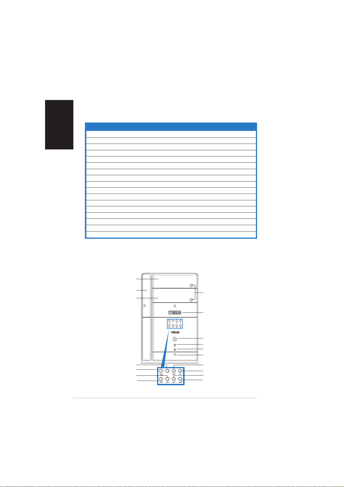
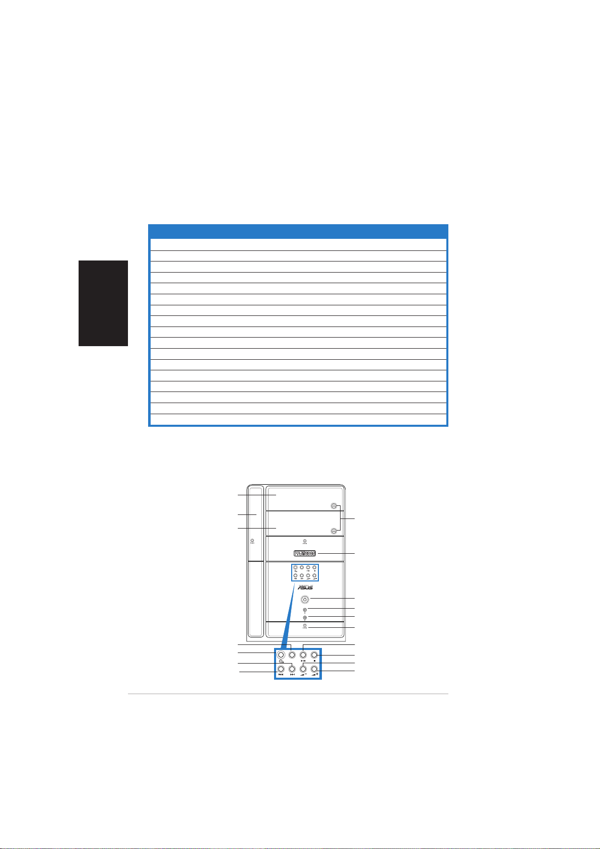
Front panel (external)Front panel (external)
Front panel (external)
Front panel (external)Front panel (external)
Optical drive doorOptical drive door
Optical drive door
Optical drive doorOptical drive door
Floppy drive doorFloppy drive door
Floppy drive door
Floppy drive doorFloppy drive door
Second optical driveSecond optical drive
Second optical drive
Second optical driveSecond optical drive
Mode buttonMode button
Mode button
Mode buttonMode button
NEXT buttonNEXT button
NEXT button
NEXT buttonNEXT button
PREVIOUS buttonPREVIOUS button
PREVIOUS button
PREVIOUS buttonPREVIOUS button
iiii
ii
iiii
doordoor
door
doordoor
CD buttonCD button
CD button
CD buttonCD button
Eject buttonEject button
Eject button
Eject buttonEject button
LED panelLED panel
LED panel
LED panelLED panel
MODE
Power buttonPower button
Power button
Power buttonPower button
Power LEDPower LED
Power LED
Power LEDPower LED
HDD LEDHDD LED
HDD LED
HDD LEDHDD LED
Front panel I/O doorFront panel I/O door
Front panel I/O door
Front panel I/O doorFront panel I/O door
PLAY/PAUSE buttonPLAY/PAUSE button
PLAY/PAUSE button
PLAY/PAUSE buttonPLAY/PAUSE button
STOP buttonSTOP button
STOP button
MODE
STOP buttonSTOP button
Volume down buttonVolume down button
Volume down button
Volume down buttonVolume down button
Volume up buttonVolume up button
Volume up button
Volume up buttonVolume up button
Page 3
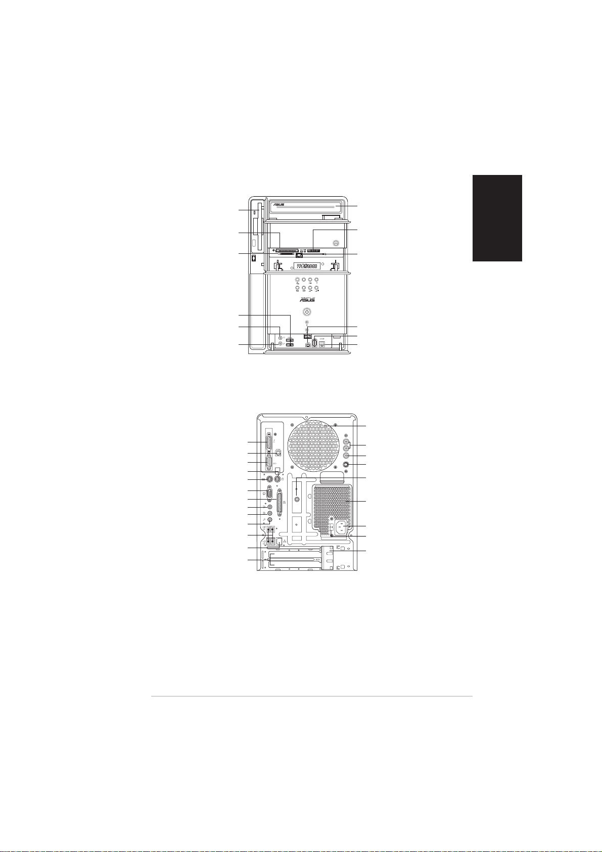
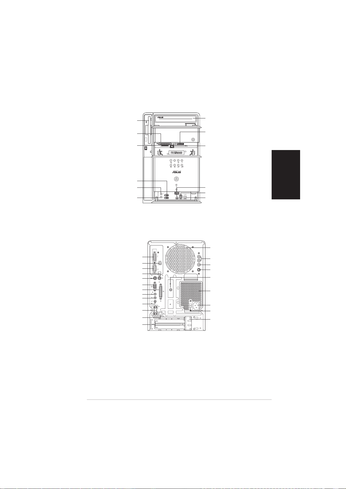
Front panel (internal)Front panel (internal)
Front panel (internal)
Front panel (internal)Front panel (internal)
Floppy disk driveFloppy disk drive
Floppy disk drive
Floppy disk driveFloppy disk drive
®®
®
CompactFlashCompactFlash
CompactFlash
CompactFlashCompactFlash
Microdrive™ card slotMicrodrive™ card slot
Microdrive™ card slot
Microdrive™ card slotMicrodrive™ card slot
SmartMediaSmartMedia
SmartMedia
SmartMediaSmartMedia
Rear panelRear panel
Rear panel
Rear panelRear panel
Optical S/PDIF Out portOptical S/PDIF Out port
Optical S/PDIF Out port
Optical S/PDIF Out portOptical S/PDIF Out port
®®
®
®®
USB 2.0 portsUSB 2.0 ports
USB 2.0 ports
USB 2.0 portsUSB 2.0 ports
Headphone portHeadphone port
Headphone port
Headphone portHeadphone port
Microphone portMicrophone port
Microphone port
Microphone portMicrophone port
DVI-out portDVI-out port
DVI-out port
DVI-out portDVI-out port
PS/2 mouse portPS/2 mouse port
PS/2 mouse port
PS/2 mouse portPS/2 mouse port
PS/2 keyboard portPS/2 keyboard port
PS/2 keyboard port
PS/2 keyboard portPS/2 keyboard port
Parallel portParallel port
Parallel port
Parallel portParallel port
Line Out portLine Out port
Line Out port
Line Out portLine Out port
Microphone portMicrophone port
Microphone port
Microphone portMicrophone port
USB 2.0 portsUSB 2.0 ports
USB 2.0 ports
USB 2.0 portsUSB 2.0 ports
LAN (RJ-45) portLAN (RJ-45) port
LAN (RJ-45) port
LAN (RJ-45) portLAN (RJ-45) port
Expansion slotExpansion slot
Expansion slot
Expansion slotExpansion slot
®®
//
/
//
card slot card slot
card slot
card slot card slot
Serial portSerial port
Serial port
Serial portSerial port
VGA portVGA port
VGA port
VGA portVGA port
Line In portLine In port
Line In port
Line In portLine In port
coverscovers
covers
coverscovers
Optical driveOptical drive
Optical drive
Optical driveOptical drive
(optional)(optional)
(optional)
(optional)(optional)
®®
®
MemoryStickMemoryStick
MemoryStick
MemoryStickMemoryStick
MemoryStick Pro™ cardMemoryStick Pro™ card
MemoryStick Pro™ card
MemoryStick Pro™ cardMemoryStick Pro™ card
slotslot
slot
slotslot
Secure DigitalSecure Digital
Secure Digital
Secure DigitalSecure Digital
MultimediaCard slotMultimediaCard slot
MultimediaCard slot
MultimediaCard slotMultimediaCard slot
MODE
4-pin IEEE 1394a port4-pin IEEE 1394a port
4-pin IEEE 1394a port
4-pin IEEE 1394a port4-pin IEEE 1394a port
6-pin IEEE 1394a port6-pin IEEE 1394a port
6-pin IEEE 1394a port
6-pin IEEE 1394a port6-pin IEEE 1394a port
Optical S/PDIF In portOptical S/PDIF In port
Optical S/PDIF In port
Optical S/PDIF In portOptical S/PDIF In port
Chassis fan ventChassis fan vent
Chassis fan vent
Chassis fan ventChassis fan vent
Audio in portsAudio in ports
Audio in ports
Audio in portsAudio in ports
Video in portVideo in port
Video in port
Video in portVideo in port
S-Video portS-Video port
S-Video port
S-Video portS-Video port
Radio antenna portRadio antenna port
Radio antenna port
Radio antenna portRadio antenna port
Power supply unitPower supply unit
Power supply unit
RADIO ANY
Power supply unitPower supply unit
fan ventfan vent
fan vent
fan ventfan vent
Power connectorPower connector
Power connector
Power connectorPower connector
Voltage selectorVoltage selector
Voltage selector
Voltage selectorVoltage selector
Expansion card lockExpansion card lock
Expansion card lock
Expansion card lockExpansion card lock
®®
//
/
//
™™
™
™™
//
/
//
English
iiiiii
iii
iiiiii
Page 4
English
Installation
IMPORTANT! IMPORTANT!
IMPORTANT! Refer to the system user guide for installation details
IMPORTANT! IMPORTANT!
and other system information.
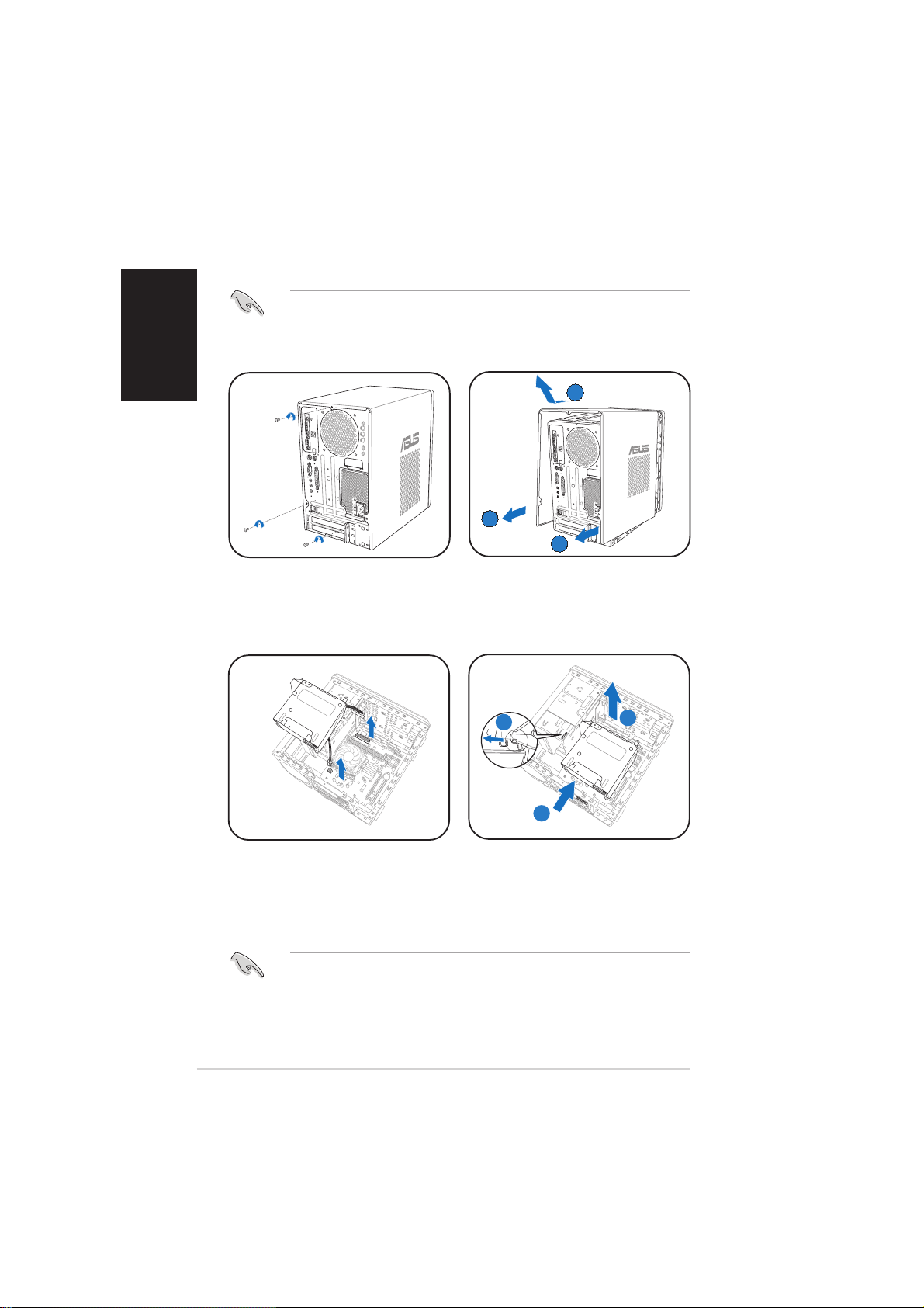
Removing the coverRemoving the cover
Removing the cover
Removing the coverRemoving the cover
BB
B
BB
AA
A
AA
AA
A
AA
1. Locate and remove three
cover screws.
Removing the power supply unitRemoving the power supply unit
Removing the power supply unit
Removing the power supply unitRemoving the power supply unit
1. Disconnect all power plugs
from the system components
and the motherboard, then
remove the PSU screw.
2. Pull the cover toward the rear
panel (A), then lift (B).
AA
A
AA
2. Slide the PSU to the left (A)
until the side hook is
disengaged. Push the PSU
toward the front panel (B),
then lift (C).
IMPORTANT! IMPORTANT!
IMPORTANT! When removing the PSU, make sure to hold or support it
IMPORTANT! IMPORTANT!
firmly. The unit might accidentally drop and damage the other system
components.
CC
C
CC
BB
B
BB
iviv
iv
iviv
Page 5
Installing the CPUInstalling the CPU
Installing the CPU
Installing the CPUInstalling the CPU
English
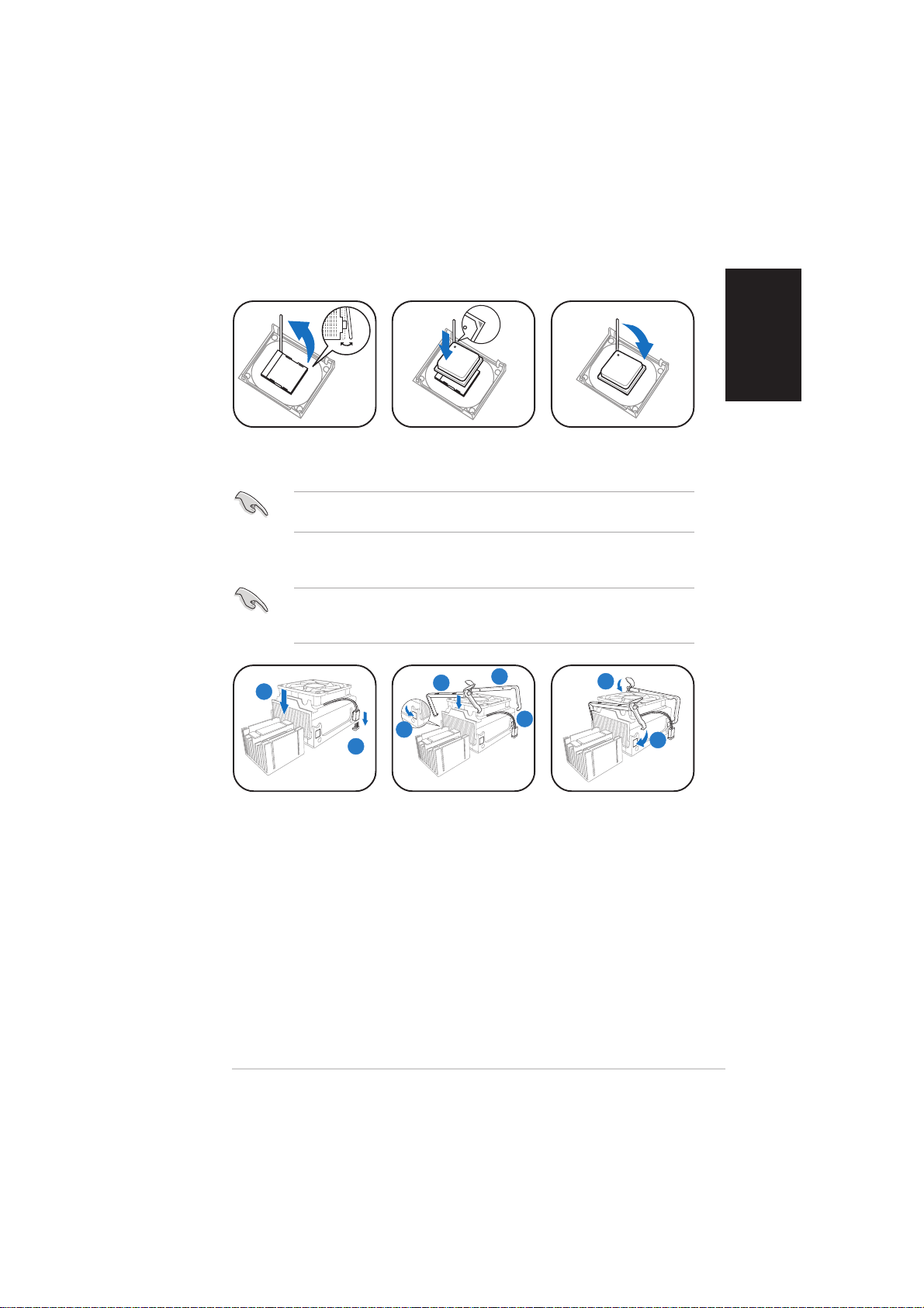
1. Press the CPU
socket lever
sideways, then lift.
IMPORTANT! IMPORTANT!
IMPORTANT! Make sure to install the CPU fan and heatsink assembly
IMPORTANT! IMPORTANT!
on top of the installed CPU.
Installing the CPU fan and heatsink assemblyInstalling the CPU fan and heatsink assembly
Installing the CPU fan and heatsink assembly
Installing the CPU fan and heatsink assemblyInstalling the CPU fan and heatsink assembly
IMPORTANT! IMPORTANT!
IMPORTANT! Make sure to turn off your computer and unplug the
IMPORTANT! IMPORTANT!
cable from the power source before installing the CPU fan and heatsink
assembly.
11
1
11
1. Place the CPU fan
and heatsink
assembly on top
of the installed
CPU, making sure
it fits the
retention module.
2. Connect the CPU
fan cable to the
CPU fan
connector on the
motherboard.
2. Insert the CPU into
the socket until it
fits in place.
33
3
33
44
4
44
22
2
22
3. Align the metal
clips to the side
rail of the CPU fan
and heatsink
assembly, with
the locking levers
in the reverse
orientation.
4. Snap the hook of
each metal clip
into the hole of
the retention
33
3
33
3. Push down the
socket lever to
secure the CPU.
55
5
55
44
4
44
5. Carefully press
down each locking
lever and hook its
end into the hole
of the retention
module.
module.
55
5
55
vv
v
vv
Page 6
English
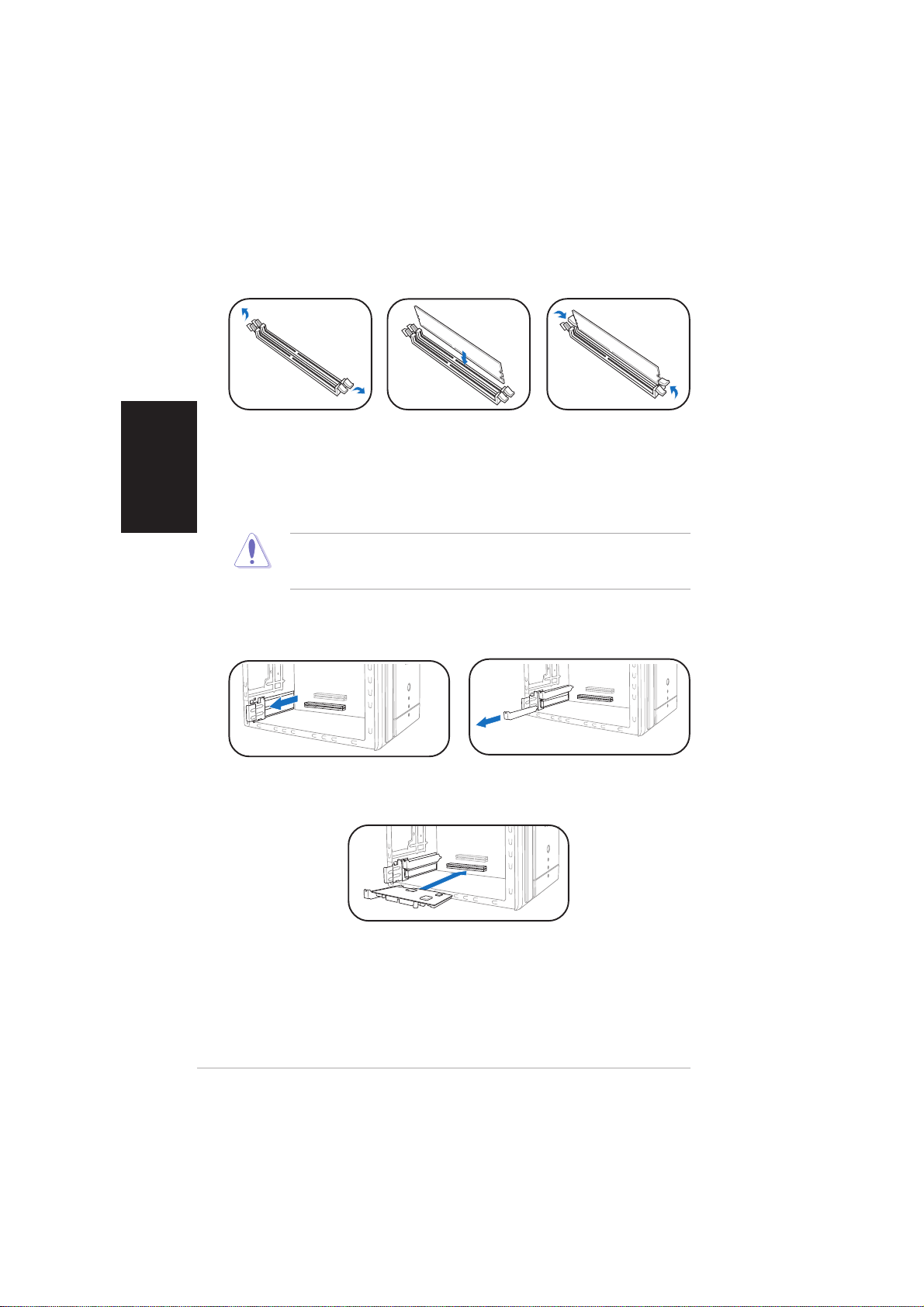
Installing memory module(s)Installing memory module(s)
Installing memory module(s)
Installing memory module(s)Installing memory module(s)
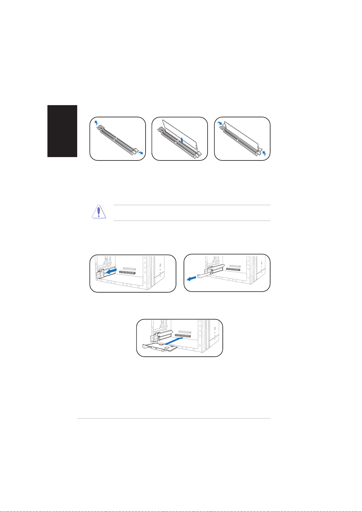
1. Press the
retaining clips of
the DIMM socket
outward.
CAUTION! CAUTION!
CAUTION! A DDR DIMM is keyed with a notch so that it fits in only one
CAUTION! CAUTION!
direction. Do not force a DIMM into a socket to avoid damaging the DIMM!
Installing expansion cardsInstalling expansion cards
Installing expansion cards
Installing expansion cardsInstalling expansion cards
1. Pull the expansion card lock to
the direction of the arrow.
2. Align a DIMM on
the socket.
3. Insert the DIMM
firmly to the
socket until the
retaining clips snap
back in place.
2. Remove the metal bracket
opposite the slot you intend to
use.
vivi
vi
vivi
3. Align the card connector
with the slot, then press
firmly.
Page 7
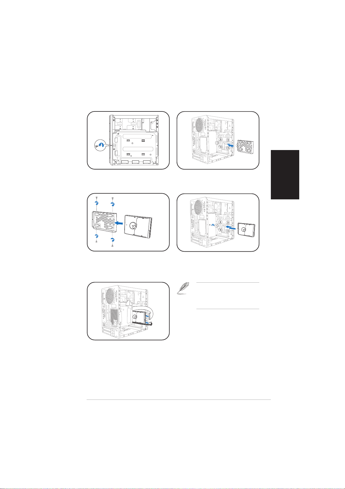
Installing a hard disk driveInstalling a hard disk drive
Installing a hard disk drive
Installing a hard disk driveInstalling a hard disk drive
English
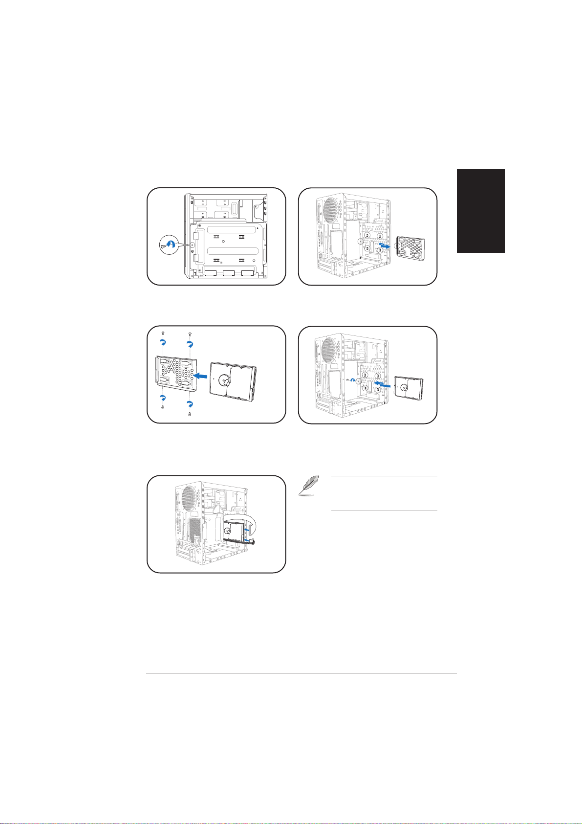
1. Remove the HDD tray lock
screw.
3. Place a hard disk drive on the
tray, then secure it with four
screws.
2. Slide the HDD tray outward.
4. Reinstall the HDD tray inside
the chassis, then secure the
HDD tray with the lock screw.
NOTE. NOTE.
NOTE. Refer to the User
NOTE. NOTE.
Guide for details on installing a
Serial ATA HDD.
5. Connect the power and signal
cables to the connectors at
the back of the drive.
viivii
vii
viivii
Page 8
English
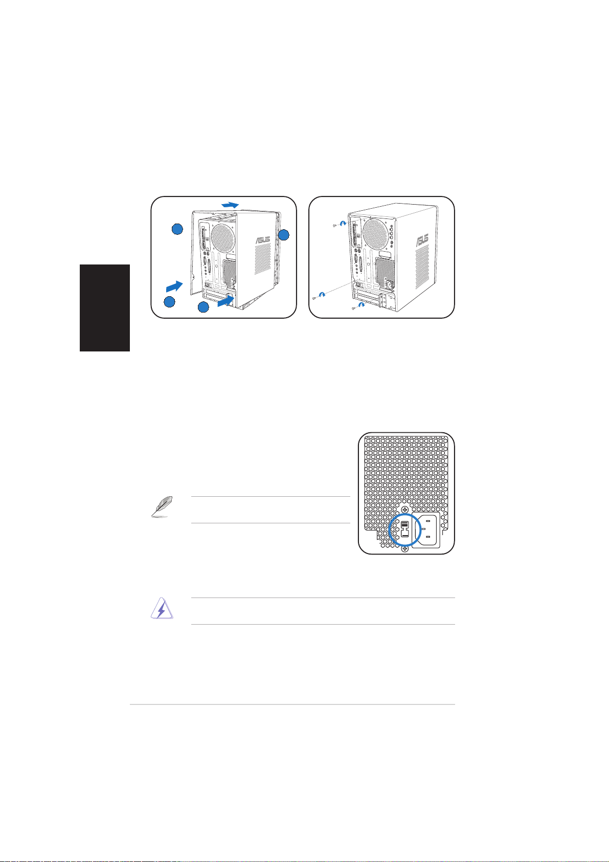
Replacing the coverReplacing the cover
Replacing the cover
Replacing the coverReplacing the cover
BB
B
BB
AA
A
AA
AA
A
AA
BB
B
BB
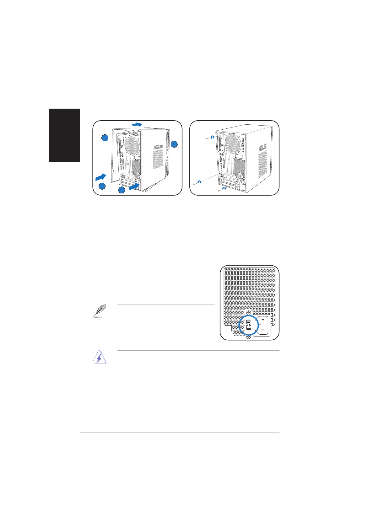
1. Fit the cover tabs with the
chassis rail and the front panel
2. Secure the cover with three
screws.
tabs (A), then lower the rear
edge of the cover as shown
(B).
Selecting the voltage
The PSU has a 115 V/230 V voltage selector
switch located beside the power connector. Use
this switch to select the appropriate system
input voltage according to the voltage supply in
your area.
NOTE.NOTE.
NOTE. The voltage selector is set to
NOTE.NOTE.
230 V by default.
If the voltage supply in your area is 100-127 V,
set the switch to 115 V. If the voltage supply in
your area is 200-240 V, set the switch to 230 V.
WARNING! WARNING!
WARNING! Setting the switch to 115 V in a 230 V environment will
WARNING! WARNING!
seriously damage the system!
viiiviii
viii
viiiviii
Page 9
®
MODE
T2-AH1/AH2
Système barebone
Guide d’installation rapide
Français
Copyright © 2005 ASUSTeK COMPUTER INC. Tous droits ré servé s.Copyright © 2005 ASUSTeK COMPUTER INC. Tous droits ré servé s.
Copyright © 2005 ASUSTeK COMPUTER INC. Tous droits ré servé s.
Copyright © 2005 ASUSTeK COMPUTER INC. Tous droits ré servé s.Copyright © 2005 ASUSTeK COMPUTER INC. Tous droits ré servé s.
Page 10
Français
Contenu du carton
Vérifiez que les éléments suivants accompagnent bien votre T2-AH1/AH2.
Contactez votre revendeur immédiatement si l’un d’entre eux était
manquant ou endommagé.
Description des é l é mentsDescription des é l é ments
Description des é l é ments
Description des é l é mentsDescription des é l é ments
1.1.
Systè me barebone ASUS T2-AH1/AH2 Systè me barebone ASUS T2-AH1/AH2
1.
Systè me barebone ASUS T2-AH1/AH2 avec
1.1.
Systè me barebone ASUS T2-AH1/AH2 Systè me barebone ASUS T2-AH1/AH2
•
Carte mère ASUS
•
Alimentation 250 W PFC
•
Port Gigabit LAN
•
Assemblage dissipateur/ventilateur pour CPU•Lecteur de cartes 7-en-1
•
2 x baies 5.25”
•
1 x baie pour lecteur de disquettes 3.5”
•
Panneau de LED
2.2.
C â blesC â bles
2.
C â bles
2.2.
C â blesC â bles
•
Câble d’alimentation
•
Câble Serial ATA
•
Câble d’alimentation Serial ATA
3.3.
CD de supportCD de support
3.
CD de support
3.3.
CD de supportCD de support
4.4.
ManuelManuel
4.
Manuel
4.4.
ManuelManuel
5.5.
Elé ments optionnelsElé ments optionnels
5.
Elé ments optionnels
5.5.
Elé ments optionnelsElé ments optionnels
•
Lecteur optique
•
Lecteur de disquettes
(CD-ROM/CD-RW/DVD-ROM/DVD-RW)
•
6 x ports USB 2.0
•
2 x ports IEEE 1394a
•
Port de sortie S/PDIF
•
Module radio FM et antenne
•
1 x baie pour disque dur 3.5”
•
Boutons de lecture Audio DJ
Caractéristiques
Façade (externe)
Trappe du lecteur optiqueTrappe du lecteur optique
Trappe du lecteur optique
Trappe du lecteur optiqueTrappe du lecteur optique
Trappe du lecteur deTrappe du lecteur de
Trappe du lecteur de
Trappe du lecteur deTrappe du lecteur de
Seconde trappe deSeconde trappe de
Seconde trappe de
Seconde trappe deSeconde trappe de
Bouton PRECEDENTBouton PRECEDENT
Bouton PRECEDENT
Bouton PRECEDENTBouton PRECEDENT
iiii
ii
iiii
disquettesdisquettes
disquettes
disquettesdisquettes
lecteur optiquelecteur optique
lecteur optique
lecteur optiquelecteur optique
Bouton ModeBouton Mode
Bouton Mode
Bouton ModeBouton Mode
Bouton CDBouton CD
Bouton CD
Bouton CDBouton CD
Bouton SUIVANTBouton SUIVANT
Bouton SUIVANT
Bouton SUIVANTBouton SUIVANT
Bouton d’éjectionBouton d’éjection
Bouton d’éjection
Bouton d’éjectionBouton d’éjection
LEDsLEDs
LEDs
LEDsLEDs
MODE
Bouton d’ alimentationBouton d’ alimentation
Bouton d’ alimentation
Bouton d’ alimentationBouton d’ alimentation
LED d’ alimentationLED d’alimentation
LED d’ alimentation
LED d’ alimentationLED d’alimentation
LED du disque durLED du disque dur
LED du disque dur
LED du disque durLED du disque dur
Trappe d’ E/S en faç adeTrappe d’ E/S en faç ade
Trappe d’ E/S en faç ade
Trappe d’ E/S en faç adeTrappe d’ E/S en faç ade
Bouton PLAY/PAUSEBouton PLAY/PAUSE
Bouton PLAY/PAUSE
Bouton PLAY/PAUSEBouton PLAY/PAUSE
Bouton STOPBouton STOP
Bouton STOP
MODE
Bouton STOPBouton STOP
Bouton baisse du volumeBouton baisse du volume
Bouton baisse du volume
Bouton baisse du volumeBouton baisse du volume
Bouton hausse du volumeBouton hausse du volume
Bouton hausse du volume
Bouton hausse du volumeBouton hausse du volume
Page 11
Façade (interne)Façade (interne)
Façade (interne)
Façade (interne)Façade (interne)
Lecteur de disquettesLecteur de disquettes
Lecteur de disquettes
Lecteur de disquettesLecteur de disquettes
Slot pour cartesSlot pour cartes
Slot pour cartes
Slot pour cartesSlot pour cartes
CompactFlashCompactFlash
CompactFlash
CompactFlashCompactFlash
Microdrive™Microdrive™
Microdrive™
Microdrive™Microdrive™
Slot pour cartesSlot pour cartes
Slot pour cartes
Slot pour cartesSlot pour cartes
SmartMediaSmartMedia
SmartMedia
SmartMediaSmartMedia
Ports USB 2.0Ports USB 2.0
Ports USB 2.0
Ports USB 2.0Ports USB 2.0
Port CasquePort Casque
Port Casque
Port CasquePort Casque
Port MicrophonePort Microphone
Port Microphone
Port MicrophonePort Microphone
ArrièreArriè re
Arrière
ArrièreArriè re
Port S/PDIF optiquePort S/PDIF optique
Port S/PDIF optique
Port S/PDIF optiquePort S/PDIF optique
Port souris PS/2Port souris PS/2
Port souris PS/2
Port souris PS/2Port souris PS/2
Port clavier PS/2Port clavier PS/2
Port clavier PS/2
Port clavier PS/2Port clavier PS/2
Port Parallè lePort Parallè le
Port Parallè le
Port Parallè lePort Parallè le
Port Line OutPort Line Out
Port Line Out
Port Line OutPort Line Out
Port MicrophonePort Microphone
Port Microphone
Port MicrophonePort Microphone
Ports USB 2.0Ports USB 2.0
Ports USB 2.0
Ports USB 2.0Ports USB 2.0
Port LAN (RJ-45)Port LAN (RJ-45)
Port LAN (RJ-45)
Port LAN (RJ-45)Port LAN (RJ-45)
Couverture desCouverture des
Couverture des
Couverture desCouverture des
slots d’ extensionslots d’ extension
slots d’ extension
slots d’ extensionslots d’ extension
®®
®
®®
//
/
//
®®
®
®®
DVI-outDVI-out
DVI-out
DVI-outDVI-out
Port Sé riePort Série
Port Sé rie
Port Sé riePort Série
Port VGAPort VGA
Port VGA
Port VGAPort VGA
Port Line InPort Line In
Port Line In
Port Line InPort Line In
Lecteur optiqueLecteur optique
Lecteur optique
Lecteur optiqueLecteur optique
(optionnel)(optionnel)
(optionnel)
(optionnel)(optionnel)
Slot pour cartesSlot pour cartes
Slot pour cartes
Slot pour cartesSlot pour cartes
MemoryStickMemoryStick
MemoryStick
MemoryStickMemoryStick
MemoryStick Pro™MemoryStick Pro™
MemoryStick Pro™
MemoryStick Pro™MemoryStick Pro™
Slot Secure DigitalSlot Secure Digital
Slot Secure Digital
Slot Secure DigitalSlot Secure Digital
MultimediaCardMultimediaCard
MultimediaCard
MultimediaCardMultimediaCard
MODE
Port IEEE 1394a 4 brochesPort IEEE 1394a 4 broches
Port IEEE 1394a 4 broches
Port IEEE 1394a 4 brochesPort IEEE 1394a 4 broches
Port IEEE 1394a 6 brochesPort IEEE 1394a 6 broches
Port IEEE 1394a 6 broches
Port IEEE 1394a 6 brochesPort IEEE 1394a 6 broches
Port S/PDIF optiquePort S/PDIF optique
Port S/PDIF optique
Port S/PDIF optiquePort S/PDIF optique
Ventilation châ ssisVentilation châ ssis
Ventilation châ ssis
Ventilation châ ssisVentilation châ ssis
Audio-inAudio-in
Audio-in
Audio-inAudio-in
Video-inVideo-in
Video-in
Video-inVideo-in
S-VideoS-Video
S-Video
S-VideoS-Video
Port antenne radioPort antenne radio
Port antenne radio
Port antenne radioPort antenne radio
VentilationVentilation
Ventilation
RADIO ANY
VentilationVentilation
alimentationalimentation
alimentation
alimentationalimentation
Connecteur d’ alimentaitonConnecteur d’ alimentaiton
Connecteur d’ alimentaiton
Connecteur d’ alimentaitonConnecteur d’ alimentaiton
S é lecteur de tensionsS é lecteur de tensions
S é lecteur de tensions
S é lecteur de tensionsS é lecteur de tensions
Verrou des cartesVerrou des cartes
Verrou des cartes
Verrou des cartesVerrou des cartes
d ’ extensiond ’ extension
d ’ extension
d ’ extensiond ’ extension
®®
®
®®
//
/
//
™™
™
™™
//
/
//
Français
iiiiii
iii
iiiiii
Page 12

Français
Installation
IMPORTANT ! IMPORTANT !
IMPORTANT ! reportez-vous au manuel pour plus de détails
IMPORTANT ! IMPORTANT !
d’installation et autres informations système.
Ouvrir le châssisOuvrir le châssis
Ouvrir le châssis
Ouvrir le châssisOuvrir le châssis
BB
B
BB
AA
A
AA
AA
A
AA
1. Localisez et dévissez les trois
vis de châssis.
Enlever l’alimentationEnlever l’alimentation
Enlever l’alimentation
Enlever l’alimentationEnlever l’alimentation
1. Déconnectez toutes les prises
d’alimentaiton du système et
des composants puis enlevez
la vis de l’alimentation.
IMPORTANT ! IMPORTANT !
IMPORTANT ! lorsque vous enlevez l’alimentation assurez-vous de
IMPORTANT ! IMPORTANT !
bien la tenir car elle pourrait tomber et endommager les autres
composants du système.
2. Tirez vers l’arrière (A), puis
levez (B).
CC
C
AA
A
AA
BB
B
BB
CC
2. Glissez l’alimentation vers la
gauche (A) jusqu’à ce que les
crochets soient désengagés.
Poussez l’alimentation vers la
façade (B), puis soulevez (C).
iviv
iv
iviv
Page 13

Installer le CPUInstaller le CPU
Installer le CPU
Installer le CPUInstaller le CPU
1. Pressez le levier
du socket du CPU
latéralement, puis
souvevez.
IMPORTANT ! IMPORTANT !
IMPORTANT ! Assurez-vous de bien installer le système de ventilation
IMPORTANT ! IMPORTANT !
sur le CPU installé.
Installer le système de refroidissement du CPUInstaller le système de refroidissement du CPU
Installer le système de refroidissement du CPU
Installer le système de refroidissement du CPUInstaller le système de refroidissement du CPU
IMPORTANT! IMPORTANT!
IMPORTANT! Assurez-vous d’éteindre l’ordinateur et de débrancher le
IMPORTANT! IMPORTANT!
câble d’alimentation avant d’installer l’ensemble dissipateur/ventilateur.
11
1
11
1. Placez le système
de refroidissement
du CPU sur le CPU
installé en vous
assurant qu’il entre
dans le module de
rétention.
2. Connectez le câble
du ventilateur du
CPU au connecteur
de la carte mère.
2. Insérez le CPU
dans le socket
jusqu’à ce qu’il
soit bien en place.
44
4
44
22
2
22
3. Alignez les clips
métalliques sur
les rails latéraux
de l’ensemble
dissipateurventilateur, avec
les leviers de
verrouillage
ouverts.
4. Accrochez le
crochet de
33
3
33
3
33
33
3. Rabaissez le levier
du CPU pour le
verrouiller.
55
5
55
44
4
44
5. Rabaissez avec
soin chaque levier
de verrouillage et
accrochez-en
l’extrémité au trou
du module de
rétention.
chaque clip
métallique dans le
trou du module de
rétention.
Français
55
5
55
vv
v
vv
Page 14
Installer des modules de mémoireInstaller des modules de mémoire
Installer des modules de mémoire
Installer des modules de mémoireInstaller des modules de mémoire
Français
1. Pressez les clips
de rétention des
sockets DIMM
vers l’extérieur.
ATTENTION ATTENTION
ATTENTION
ATTENTION ATTENTION
sorte qu’il ne puisse entrer que dans un seul sens. Ne forcez pas
inutilement sur un module pour ne pas l’endommager.
Installer les cartes d’extensionInstaller les cartes d’extension
Installer les cartes d’extension
Installer les cartes d’extensionInstaller les cartes d’extension
1. Tirez le verrou de cartes
d’extension dans le sens de la
flèche.
2. Alignez un module
sur le socket.
! !
! Un module DIMM DDR est verrouillé par une encoche de
! !
2. Enlevez la protection
3. Insérez le module
DIMM dans le
socket jusqu’à ce
que lec clips
reviennent en
place.
métallique du slot que vous
voulez utiliser.
vivi
vi
vivi
3. Positionnez le connecteur de
la carte sur le slot, puis
pressez fermement.
Page 15
Installer un disque durInstaller un disque dur
Installer un disque dur
Installer un disque durInstaller un disque dur
1. Dévissez le plateau du disque
dur.
3. Placez le disque dur sur le
plateau puis fixez-le avec
quatre vis.
2. Sortez le plateau.
4. Reinstallez le plateau du
disque dur dans le châssis puis
remettez la vis de fixation.
NOTE. NOTE.
NOTE. reportez-vous au
NOTE. NOTE.
manuel pour plus de détails sur
l’installation d’un disque dur
Serial ATA.
Français
5. Connectez les câbles de signal
et d’alimentation aux prises à
l’arrière du disque.
viivii
vii
viivii
Page 16
Français
Refermer le châssisRefermer le châssis
Refermer le châssis
Refermer le châssisRefermer le châssis
BB
B
BB
AA
A
AA
AA
A
AA
BB
B
BB
1. Alignez les onglets du capot
2. Fixez le capot avec trois vis.
avec le rail du châssis et les
onglets de la façade (A), puis
baissez le bord arrière comme
indiqué (B).
Choisir le voltage
L’alimentation est équipée d’un sélecteur de
tension 115 V/230 V situé près du connecteur
d’alimentation. Utilisez cet interrupteur pour
choisir la tension d’entrée appropriée à votre
région.
NOTE.NOTE.
NOTE. le sélecteur de tension est placé
NOTE.NOTE.
sur 230 V par défaut.
Si la tension dans votre région est de 100-127
V, passez l’interrupteur sur 115 V. Si la tension
dans votre région est de 200-240 V, passez l’interrupteur sur 230 V.
ATTENTION ! ATTENTION !
ATTENTION ! Paser l’interrupteur sur 115 V dans une région à 230 V
ATTENTION ! ATTENTION !
endommagera gravement le système !
viiiviii
viii
viiiviii
Page 17
®
MODE
T2-AH1/AH2
Copyright 2005 ASUSTeK COMPUTER INC. All Rights Reserved.
Page 18

1. T2-AH1/AH2
6 USB 2.0
250 W PFC 2 IEEE 1394a
Gigabit LAN S/PDIF
CPU 7-in-1
2 x 5.25 FM
1 x 3.5 1 x 3.5
LED Audio DJ
2.
Serial ATA
Serial ATA
3.
4.
5.
(CD-ROM/CD-RW/DVD-ROM/DVD-RW)
( )
LED
MODE
I/O
CD
iiii
ii
iiii
MODE
/
Page 19

( )
( )
CompactFlash Microdrive
SmartMedia
USB 2.0
DVI
S/PDIF
PS/2
PS/2
VGA
MemoryStick MemoryStick
Pro
Secure Digital
MultimediaCard
MODE
4-pin IEEE 1394a
6-pin IEEE 1394a
RADIO ANY
USB 2.0
LAN (RJ-45)
iiiiii
iii
iiiiii
Page 20

!
B
A
A
1.
2. (A)
(B)
A
B
C
1. 2. 5.25
(A)
!
(B)
(C)
iviv
iv
iviv
Page 21

CPU
1. CPU
CPU
1
1.
CPU
90
!
CPU
2
2. 3.
3
4
3.
3
4
5.
5
5
2.
CPU_FAN
4.
vv
v
vv
Page 22

1.
2. 3.
DDR DIMM
1. 2.
vivi
vi
vivi
3.
Page 23

1. 2.
3. 4.
Serial ATA
5.
viivii
vii
viivii
Page 24

B
B
A
1.
A
2.
230 V
100-127V
115V 200-240V
230V
! 230V 115V
viiiviii
viii
viiiviii
Page 25

®
MODE
T2-AH1/AH2
Copyright 2005 ASUSTeK COMPUTER INC. All Rights Reserved.
Page 26

1. T2-AH1/AH2
250 W PFC 2 IEEE 1394a
Gigabit LAN S/PDIF
CPU 7-in-1
2 x 5.25 FM
1 x 3.5 1 x 3.5
LED Audio DJ
2.
Serial ATA
Serial ATA
3.
4.
5.
(CD-ROM/CD-RW/DVD-ROM/DVD-RW)
( )
6 USB 2.0
LED
MODE
I/O
CD
iiii
ii
iiii
MODE
/
Page 27

( )
( )
CompactFlash Microdrive
SmartMedia
USB 2.0
DVI
S/PDIF
( )
PS/2
PS/2
VGA
MemoryStick MemoryStick
Pro
Secure Digital
MultimediaCard
MODE
4-pin IEEE 1394a
6-pin IEEE 1394a
RADIO ANY
USB 2.0
LAN (RJ-45)
iiiiii
iii
iiiiii
Page 28

!
B
A
A
1.
2. (A)
(B)
A
B
1. 2. 5.25
(A)
(C)
!
C
(B)
iviv
iv
iviv
Page 29

CPU
1. CPU
CPU
1
1.
CPU
90
!
CPU
2
2. 3.
3
4
3.
3
4
5.
5
5
2.
CPU_FAN
4.
vv
v
vv
Page 30

1.
2. 3.
DDR DIMM
1. 2.
vivi
vi
vivi
3.
Page 31

1. 2.
3. 4.
Serial ATA
5.
viivii
vii
viivii
Page 32

B
B
A
1.
A
2.
230 V
100-127V
115V 200-240V
230V
! 230V 115V
viiiviii
viii
viiiviii
Page 33

®
MODE
T2-AH1/AH2
©©
©
©©
Page 34

• •
• •
• •
• •
• •
• •
• •
•
•
•
•
•
MODE
MODE
iiii
ii
iiii
Page 35

®
™
®®
®
®®
™™
™
™™
®
MODE
RADIO ANY
™™
™
™™
iiiiii
iii
iiiiii
Page 36

BB
B
BB
AA
A
AA
AA
A
AA
CC
C
AA
A
AA
BB
B
BB
CC
iviv
iv
iviv
Page 37

33
3
33
3
11
1
11
22
2
22
33
44
4
44
33
44
4
44
55
5
55
55
5
55
vv
v
vv
Page 38

vivi
vi
vivi
Page 39

viivii
vii
viivii
Page 40

BB
B
BB
AA
A
AA
AA
A
AA
BB
B
BB
viiiviii
viii
viiiviii
Page 41

®
T2-AH1/AH2
MODE
©
Page 42

• •
• •
• •
• •
•
•
”
”
• •
•
•
•
•
•
•
•
”
MODE
MODE
Page 43

™
®
®
™
®
MODE
RADIO ANY
™
Page 44

Page 45

Page 46

Page 47

Page 48

Page 49

®
MODE
T2-AH1/AH2
Barebone Sistemi
H›zl› Kurulum K›lavuzu
Türkçe
Telif Hakk› © 2005 ASUSTeK COMPUTER INC. Tüm Haklar› Sakl›d›r.
Page 50

Türkçe
Sistem paketi muhteviyat›
T2-AH1/AH2 sistem paketinizde afla¤›daki ürünlerin oldu¤unu kontrol edin.
Ürünlerden herhangi biri hasar görmüflse ya da kay›psa derhal bayiiniz ile temasa
geçiniz.
Ürün tan›m›
1. ASUS T2-AH1/AH2 barebone sistemi
•
ASUS anakart
•
250 W PFC güç besleme ünitesi
•
Gigabit LAN girifli
•
CPU fan› ve ›s› alma komplesi
•
2 x 5.25" sürücü yuvalar›
•
1 x 3.5" floppy disk sürücü yuvas›
•
LED paneli
2. Kablolar
•
AC güç kablosu
•
Seri ATA kablosu
•
Seri ATA güç kablosu
3. Destek CD'si
4. Kullan›m K›lavuzu
5. ‹ste¤e Ba¤l› Ürünler
•
Optik sürücü (CD-ROM/CD-RW/DVD-ROM/DVD-RW)
•
Floppy disk sürücüsü
•
6 x USB 2.0 girifli
•
2 x IE EE 1394a girifli
•
S/PDIF ç›k›fl›
•
7'si 1 arada saklama kart› okuyucusu
•
FM radyo modülü ve radyo anteni
•
1 x 3.5" sabit disk sürücü yuvas›
•
Audio DJ çalma dü¤meleri
Özellikler
Ön panel (harici)
Optik sürücü kap›s›
Floppy sürücü kap›s›
‹kinci optik sürücü kap›s›
SONRAK‹ dü¤mesi
iiii
ii
iiii
Mod dü¤mesi
CD dü¤mesi
ÖNCEK‹ dü¤mesi
Ç›karma Dü¤mesi
LED paneli
MODE
Güç Dü¤mesi
Güç LED Göstergesi
HDD LED Göstergesi
Ön panel I/O kap›s›
ÇAL/DURAKLAT dü¤mesi
MODE
DURDUR dü¤mesi
Ses k›sma dü¤mesi
Ses açma dü¤mesi
Page 51

Ön panel (dahili)
Floppy disk sürücüsü
CompactFlash®/
Microdrive™ kart yuvas›
SmartMedia
®
kart yuvas›
USB 2.0 giriflleri
Kulakl›k girifli
Mikrofon girifli
Arka panel
Optik S/PDIF girifli
PS/2 fare girifli
PS/2 klavye girifli
Paralel girifl
Mikrofon girifli
USB 2.0 giriflleri
LAN (RJ-45) girifli
Geniflletme yuvas›
DVI-outDVI-out
DVI-out
DVI-outDVI-out
Seri girifl
VGA girifli
Hat Ç›k›fl›
Hat Girifli
kapaklar›
Optik sürücü (iste¤e ba¤l›)
MemoryStick
®
/MemoryStick
Türkçe
Pro™ kart yuvas›
Secure Digital™/
Multimedya Kart› yuvas›
MODE
4-pimli IEEE 1394a girifli
6-pimli IEEE 1394a girifli
Optik S/PDIF girifli
fiasi fan havaland›rmas›
Audio-inAudio-in
Audio-in
Audio-inAudio-in
Video-inVideo-in
Video-in
Video-inVideo-in
S-VideoS-Video
S-Video
S-VideoS-Video
Radyo anteni girifli
RADIO ANY
Güç besleme ünitesi fan
havaland›rmas›
Güç konektörü
Voltaj seçicisi
Geniflletme kart› kilidi
iiiiii
iii
iiiiii
Page 52

Kurulum
Türkçe
ÖNEML‹! Kurulum ayr›nt›lar› ve di¤er sistem bilgileri hakk›nda sistem
kullan›c› k›lavuzuna bak›n›z.
Kapa¤›n ç›kar›lmas›
1. Üç kapak vidas›n› da yerlefltirin
ve sökün.
2. Kapa¤› arka panele (A) do¤ru
Güç beslemesi ünitesinin sökülmesi
BB
B
BB
AA
A
AA
AA
A
AA
çekin, ard›ndan (B)'yi kald›r›n.
CC
C
AA
A
AA
CC
1. Tüm güç fifllerini sistem
komponentlerinden ve ana
karttan sökün, ard›ndan PSU
vidas›n› ç›kar›n.
ÖNEML‹! PSU'yu sökerken, do¤ru tuttu¤unuzdan ve destekledi¤inizden
emin olun. Ünite istemeden düflebilir ve di¤er sistem bileflenlerine zarar
verebilir.
iviv
iv
iviv
BB
B
BB
2. Yandaki kanca yerinden
ç›k›ncaya kadar PSU'yu sola
do¤ru (A) kayd›r›n. PSU'yu ön
panele (B) do¤ru itin, ard›ndan
(C)'yi kald›r›n.
Page 53

CPU'nun tak›lmas›
Türkçe
1. CPU soket koluna
yanlardan bast›r›n,
ard›ndan kald›r›n.
ÖNEML‹! CPU fan›n› ve ›s› alma komplesini tak›lan CPU'nun üstüne
takt›¤›n›zdan emin olun.
2. CPU'yu sokete
yerleflinceye kadar
itin.
CPU fan› ve ›s› al›c› komplesinin tak›lmas›
ÖNEML‹!
kapatt›¤›n›zdan ve kabloyu güç kayna¤›ndan çekti¤inizden emin olun.
11
1
11
1. CPU fan›n› ve ›s›
alma komplesini
tak›lan CPU'nun
üstüne yerlefltirin,
tutma modülüne
oturdu¤undan
emin olun.
2. CPU fan
kablosunu anakart
üzerinde bulunan
CPU fan
konektörüne
ba¤lay›n.
CPU fan›n› ve ›s› komplesini takmadan önce bilgisayar›n›z›
33
3
33
3
33
44
4
44
22
2
22
33
3. Kilitleme kollar›
ters yönde olacak
flekilde metal
klipsleri CPU
fan›n›n ve ›s› alma
komplesinin yan
k›za¤› ile hizalay›n.
4. Her bir metal
klipse ait kancay›
tutma modülünün
deli¤ine geçirin.
3. CPU'yu sabitlemek
için soket koluna
bast›r›n.
55
5
55
44
4
44
5. Her bir kilitleme
kolunu dikkatlice
bast›r›n ve ucunu
tutma modülünün
ucuna geçirin.
55
5
55
vv
v
vv
Page 54

Türkçe
Bellek modül(ler)inin tak›lmas›
1. DIMM soketinin
tutucu klipslerine
2. DIMM'i soket
üzerinde hizalay›n.
d›flar›ya do¤ru
bast›r›n.
D‹KKAT! DDR DIMM çentik ile eflleflmeli ve böylece sadece tek yönde
yerleflmelidir. DIMM'e zarar vermemek için DIMM'i sokete do¤ru güç
kullanarak yerlefltirmeyin!
Geniflletme kartlar›n›n tak›lmas›
1. Geniflletme kart› kilidini ok
yönünde itin.
3. Tutucu klipsler
yerine geri
oturuncaya kadar
DIMM'i sokete
düzgün bir flekilde
yerlefltirin.
2. Kullanmak istedi¤iniz yuvan›n
karfl›s›nda bulunan metal
deste¤i ç›kar›n.
vivi
vi
vivi
3. Kart konektörünü yuva ile
hizalay›n, ard›ndan düzgün
bir flekilde bast›r›n.
Page 55

Sabit disk sürücüsünün tak›lmas›
1. HDD tepsi kilidi vidas›n› ç›kar›n. 2. HDD tepsisini d›flar›ya do¤ru
kayd›r›n.
Türkçe
3. Sabit disk yuvas›n› tepsiye
yerlefltirin, ard›ndan dört viday›
da kullanarak sabitleyin.
5. Güç ve sinyal kablolar›n›
konektöre sürücünün arkas›nda
ba¤lay›n.
4. HDD tepsisini flaside yeniden
kurun, ard›ndan HDD tepsisini
kilit vidas› ile sabitleyin.
NOT. Seri ATA HDD'in tak›lmas›
hakk›ndaki ayr›nt›lar› görmek
için Kullan›m K›lavuzuna bak›n.
viivii
vii
viivii
Page 56

Türkçe
Kapa¤›n yerlefltirilmesi
BB
B
BB
AA
A
AA
AA
A
AA
BB
B
BB
1. fiasi k›za¤› ve ön panel
sekmeleri (A) ile birlikte kapak
2. Vidalar› kullanarak kapa¤›
sabitleyin.
sekmelerini yerlefltirin,
ard›ndan kapa¤›n arka kenar›n›
(B)'de gösterildi¤i gibi indirin.
Voltaj seçimi
PSU'da güç konektörünün yan›na yerlefltirilen 115
V/230 V de¤erinde voltaj seçme dü¤mesi
bulunmaktad›r. Bölgenizdeki voltaj beslemesine
göre uygun sistem girifl voltaj›n› seçmek için bu
dü¤meyi kullan›n.
NOT. Voltaj seçicisi varsay›lan olarak 230 V
de¤erine ayarlanm›flt›r.
Bölgenizdeki voltaj beslemesi 100-127 V ise,
dü¤meyi 115 V de¤erine ayarlay›n. Bölgenizdeki
voltaj beslemesi 200-240 V ise, dü¤meyi 230 V
de¤erine ayarlay›n.
UYARI! 230 V olan ortamlarda dü¤menin 115 V de¤erine ayarlanmas›
sisteme ciddi hasar verecektir!
viiiviii
viii
viiiviii
 Loading...