

Page 1
®
MODE
T2-AH1
Barebone System
Quick Installation Guide
E2157E2157
E2157
E2157E2157
English
Copyright © 2005 ASUSTeK COMPUTER INC. All Rights Reserved.Copyright © 2005 ASUSTeK COMPUTER INC. All Rights Reserved.
Copyright © 2005 ASUSTeK COMPUTER INC. All Rights Reserved.
Copyright © 2005 ASUSTeK COMPUTER INC. All Rights Reserved.Copyright © 2005 ASUSTeK COMPUTER INC. All Rights Reserved.
Page 2
System package contents
Check your T2-AH1 system package for the following items. Contact your
retailer immediately if any of the items is damaged or missing.
Item descriptionItem description
Item description
Item descriptionItem description
1.1.
ASUS T2-AH1 barebone systemASUS T2-AH1 barebone system
1.
ASUS T2-AH1 barebone system with
1.1.
ASUS T2-AH1 barebone systemASUS T2-AH1 barebone system
•
ASUS motherboard
•
250 W PFC power supply unit
•
Gigabit LAN port
•
CPU fan and heatsink assembly
•
2 x 5.25” drive bays
•
1 x 3.5” floppy disk drive bay
•
LED panel
2.2.
CablesCables
2.
Cables
2.2.
CablesCables
•
AC power cable
•
Serial ATA cable
•
Serial ATA power cable
3.3.
Support CDSupport CD
3.
Support CD
3.3.
Support CDSupport CD
4.4.
User guideUser guide
4.
User guide
4.4.
User guideUser guide
5.5.
Optional itemsOptional items
5.
Optional items
5.5.
Optional itemsOptional items
•
Optical drive
•
Floppy disk drive
(CD-ROM/CD-RW/DVD-ROM/DVD-RW)
•
6 x USB 2.0 ports
•
2 x IEEE 1394a ports
•
S/PDIF out port
•
7-in-1 storage card reader
•
FM radio module and radio antenna
•
1 x 3.5” hard disk drive bay
•
Audio DJ play buttons
Features
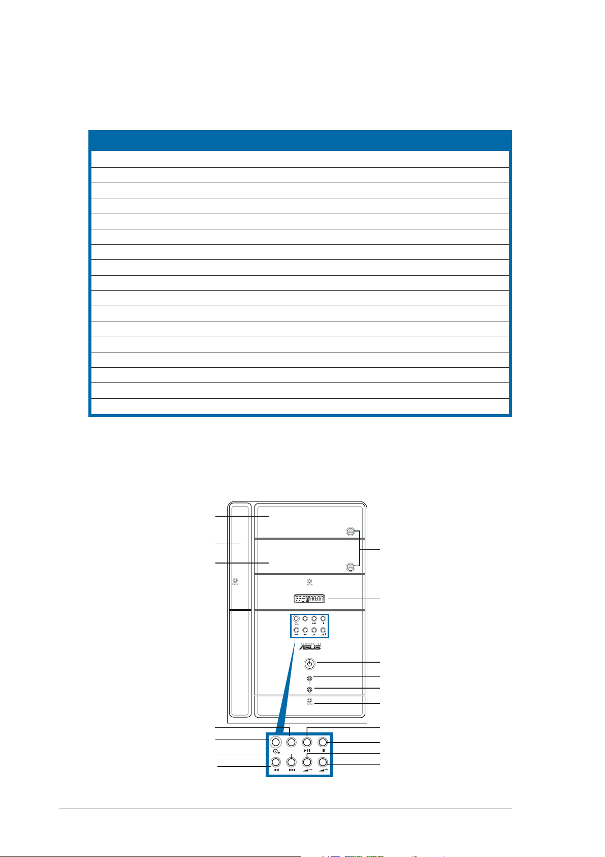
Front panel (external)Front panel (external)
Front panel (external)
Front panel (external)Front panel (external)
Optical drive doorOptical drive door
Optical drive door
Optical drive doorOptical drive door
Floppy drive doorFloppy drive door
Floppy drive door
Floppy drive doorFloppy drive door
Second optical driveSecond optical drive
Second optical drive
Second optical driveSecond optical drive
doordoor
door
doordoor
Mode buttonMode button
Mode button
Mode buttonMode button
CD buttonCD button
CD button
CD buttonCD button
NEXT buttonNEXT button
NEXT button
NEXT buttonNEXT button
PREVIOUS buttonPREVIOUS button
PREVIOUS button
PREVIOUS buttonPREVIOUS button
MODE
Eject buttonEject button
Eject button
Eject buttonEject button
LED panelLED panel
LED panel
LED panelLED panel
MODE
Power buttonPower button
Power button
Power buttonPower button
Power LEDPower LED
Power LED
Power LEDPower LED
HDD LEDHDD LED
HDD LED
HDD LEDHDD LED
Front panel I/O doorFront panel I/O door
Front panel I/O door
Front panel I/O doorFront panel I/O door
PLAY/PAUSE buttonPLAY/PAUSE button
PLAY/PAUSE button
PLAY/PAUSE buttonPLAY/PAUSE button
STOP buttonSTOP button
STOP button
STOP buttonSTOP button
Volume down buttonVolume down button
Volume down button
Volume down buttonVolume down button
Volume up buttonVolume up button
Volume up button
Volume up buttonVolume up button
iiii
ii
iiii
Page 3
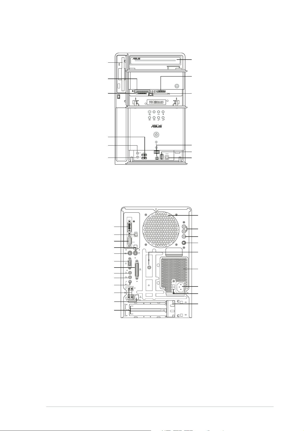
Front panel (internal)Front panel (internal)
Front panel (internal)
Front panel (internal)Front panel (internal)
Floppy disk driveFloppy disk drive
Floppy disk drive
Floppy disk driveFloppy disk drive
®®
®
CompactFlashCompactFlash
CompactFlash
CompactFlashCompactFlash
Microdrive™ card slotMicrodrive™ card slot
Microdrive™ card slot
Microdrive™ card slotMicrodrive™ card slot
®®
®
®®
SmartMediaSmartMedia
SmartMedia
SmartMediaSmartMedia
Headphone portHeadphone port
Headphone port
Headphone portHeadphone port
Microphone portMicrophone port
Microphone port
Microphone portMicrophone port
card slot card slot
card slot
card slot card slot
USB 2.0 portsUSB 2.0 ports
USB 2.0 ports
USB 2.0 portsUSB 2.0 ports
®®
//
/
//
Optical driveOptical drive
Optical drive
Optical driveOptical drive
(optional)(optional)
(optional)
(optional)(optional)
®®
®
MemoryStickMemoryStick
MemoryStick
MemoryStickMemoryStick
MemoryStick Pro™ cardMemoryStick Pro™ card
MemoryStick Pro™ card
MemoryStick Pro™ cardMemoryStick Pro™ card
slotslot
slot
slotslot
Secure DigitalSecure Digital
Secure Digital
Secure DigitalSecure Digital
MultimediaCard slotMultimediaCard slot
MultimediaCard slot
MultimediaCard slotMultimediaCard slot
MODE
4-pin IEEE 1394a port4-pin IEEE 1394a port
4-pin IEEE 1394a port
4-pin IEEE 1394a port4-pin IEEE 1394a port
6-pin IEEE 1394a port6-pin IEEE 1394a port
6-pin IEEE 1394a port
6-pin IEEE 1394a port6-pin IEEE 1394a port
Optical S/PDIF In portOptical S/PDIF In port
Optical S/PDIF In port
Optical S/PDIF In portOptical S/PDIF In port
®®
//
/
//
™™
™
™™
//
/
//
Rear panelRear panel
Rear panel
Rear panelRear panel
DVI-out portDVI-out port
DVI-out port
DVI-out portDVI-out port
Optical S/PDIF Out portOptical S/PDIF Out port
Optical S/PDIF Out port
Optical S/PDIF Out portOptical S/PDIF Out port
Serial portSerial port
Serial port
Serial portSerial port
PS/2 mouse portPS/2 mouse port
PS/2 mouse port
PS/2 mouse portPS/2 mouse port
PS/2 keyboard portPS/2 keyboard port
PS/2 keyboard port
PS/2 keyboard portPS/2 keyboard port
VGA portVGA port
VGA port
VGA portVGA port
Parallel portParallel port
Parallel port
Parallel portParallel port
Line Out portLine Out port
Line Out port
Line Out portLine Out port
Line In portLine In port
Line In port
Line In portLine In port
Microphone portMicrophone port
Microphone port
Microphone portMicrophone port
USB 2.0 portsUSB 2.0 ports
USB 2.0 ports
USB 2.0 portsUSB 2.0 ports
LAN (RJ-45) portLAN (RJ-45) port
LAN (RJ-45) port
LAN (RJ-45) portLAN (RJ-45) port
Expansion slotExpansion slot
Expansion slot
Expansion slotExpansion slot
coverscovers
covers
coverscovers
RADIO ANY
Chassis fan ventChassis fan vent
Chassis fan vent
Chassis fan ventChassis fan vent
Audio in portsAudio in ports
Audio in ports
Audio in portsAudio in ports
Video in portVideo in port
Video in port
Video in portVideo in port
S-Video portS-Video port
S-Video port
S-Video portS-Video port
Radio antenna portRadio antenna port
Radio antenna port
Radio antenna portRadio antenna port
Power supply unitPower supply unit
Power supply unit
Power supply unitPower supply unit
fan ventfan vent
fan vent
fan ventfan vent
Power connectorPower connector
Power connector
Power connectorPower connector
Voltage selectorVoltage selector
Voltage selector
Voltage selectorVoltage selector
Expansion card lockExpansion card lock
Expansion card lock
Expansion card lockExpansion card lock
iiiiii
iii
iiiiii
Page 4

Installation
IMPORTANT! IMPORTANT!
IMPORTANT! Refer to the system user guide for installation details
IMPORTANT! IMPORTANT!
and other system information.
Removing the coverRemoving the cover
Removing the cover
Removing the coverRemoving the cover
BB
B
BB
AA
A
AA
AA
A
AA
1. Locate and remove three
cover screws.
Removing the power supply unitRemoving the power supply unit
Removing the power supply unit
Removing the power supply unitRemoving the power supply unit
1. Disconnect all power plugs
from the system components
and the motherboard, then
remove the PSU screw.
2. Pull the cover toward the rear
panel (A), then lift (B).
AA
A
AA
2. Slide the PSU to the left (A)
until the side hook is
disengaged. Push the PSU
toward the front panel (B),
then lift (C).
CC
C
CC
BB
B
BB
iviv
iv
iviv
IMPORTANT! IMPORTANT!
IMPORTANT! When removing the PSU, make sure to hold or support it
IMPORTANT! IMPORTANT!
firmly. The unit might accidentally drop and damage the other system
components.
Page 5

Installing the CPUInstalling the CPU
Installing the CPU
Installing the CPUInstalling the CPU
1. Press the CPU
socket lever
sideways, then lift.
IMPORTANT! IMPORTANT!
IMPORTANT! Make sure to install the CPU fan and heatsink assembly
IMPORTANT! IMPORTANT!
on top of the installed CPU.
Installing the CPU fan and heatsink assemblyInstalling the CPU fan and heatsink assembly
Installing the CPU fan and heatsink assembly
Installing the CPU fan and heatsink assemblyInstalling the CPU fan and heatsink assembly
IMPORTANT! IMPORTANT!
IMPORTANT! Make sure to turn off your computer and unplug the
IMPORTANT! IMPORTANT!
cable from the power source before installing the CPU fan and heatsink
assembly.
11
1
11
22
2
22
2. Insert the CPU into
the socket until it
fits in place.
33
3
33
3
33
44
4
44
33
3. Push down the
socket lever to
secure the CPU.
55
5
55
44
4
44
55
5
55
1. Place the CPU fan
and heatsink
assembly on top
of the installed
CPU, making sure
it fits the
retention module.
2. Connect the CPU
fan cable to the
CPU fan
connector on the
motherboard.
3. Align the metal
clips to the side
rail of the CPU fan
and heatsink
assembly, with
the locking levers
in the reverse
orientation.
4. Snap the hook of
each metal clip
into the hole of
the retention
module.
5. Carefully press
down each locking
lever and hook its
end into the hole
of the retention
module.
vv
v
vv
Page 6

Installing memory module(s)Installing memory module(s)
Installing memory module(s)
Installing memory module(s)Installing memory module(s)
1. Press the
retaining clips of
the DIMM socket
outward.
CAUTION! CAUTION!
CAUTION! A DDR DIMM is keyed with a notch so that it fits in only one
CAUTION! CAUTION!
direction. Do not force a DIMM into a socket to avoid damaging the DIMM!
Installing expansion cardsInstalling expansion cards
Installing expansion cards
Installing expansion cardsInstalling expansion cards
2. Align a DIMM on
the socket.
3. Insert the DIMM
firmly to the
socket until the
retaining clips snap
back in place.
1. Pull the expansion card lock to
the direction of the arrow.
3. Align the card connector
with the slot, then press
firmly.
vivi
vi
vivi
2. Remove the metal bracket
opposite the slot you intend to
use.
Page 7

Installing a hard disk driveInstalling a hard disk drive
Installing a hard disk drive
Installing a hard disk driveInstalling a hard disk drive
1. Remove the HDD tray lock
screw.
3. Place a hard disk drive on the
tray, then secure it with four
screws.
2. Slide the HDD tray outward.
4. Reinstall the HDD tray inside
the chassis, then secure the
HDD tray with the lock screw.
NOTE. NOTE.
NOTE. Refer to the User
NOTE. NOTE.
Guide for details on installing a
Serial ATA HDD.
5. Connect the power and signal
cables to the connectors at
the back of the drive.
viivii
vii
viivii
Page 8

Replacing the coverReplacing the cover
Replacing the cover
Replacing the coverReplacing the cover
BB
B
BB
AA
A
AA
AA
A
AA
BB
B
BB
1. Fit the cover tabs with the
chassis rail and the front panel
2. Secure the cover with three
screws.
tabs (A), then lower the rear
edge of the cover as shown
(B).
Selecting the voltage
The PSU has a 115 V/230 V voltage selector
switch located beside the power connector. Use
this switch to select the appropriate system
input voltage according to the voltage supply in
your area.
NOTE.NOTE.
NOTE. The voltage selector is set to
NOTE.NOTE.
230 V by default.
If the voltage supply in your area is 100-127 V,
set the switch to 115 V. If the voltage supply in
your area is 200-240 V, set the switch to 230 V.
viiiviii
viii
viiiviii
WARNING! WARNING!
WARNING! Setting the switch to 115 V in a 230 V environment will
WARNING! WARNING!
seriously damage the system!
 Loading...