


s62
Table of contents
 Loading...
ASUS s62 Service Manual
service overview
T
Chapter
Service Overview
Carefully read through this chapter for a look at various components of
the notebook and necessary cautions and tools before performing any
service and repairs.
o provide the best service and support for the ASUS S62 Series, we have provided the
below information for technicians from distributors and resellers to perform the
complete notebook disassembly and assembly. But before performing the procedures,
please be sure to read through the overview in this chapter for component overview,
cautions and tools to avoid any unwarranted damages to the notebook’s hardware.
The following chapter includes:
• S62 Series Overview
• Components
• Precautions
• Appropriate Tools
1-1
service overview
y
S62 Series Overview and Components
The ASUS S62 Series Notebook is a product combining the power of Intel®
Pentium-M CPU. In this section, an overview for the S62 Series, along with its
components, will be presented.
OVERVIEW
Mic input
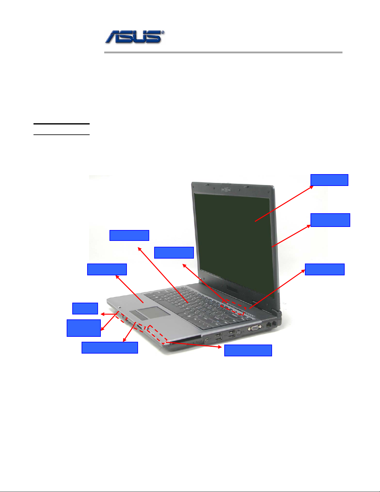
S62 Series Overview
The illustrations below show the notebook’s overview from front view, right side view,
left side view, and rear side view. Most of the parts will be discussed in this manual.
Keyboard
Instant Ke
TouchPad
Power switch
LCD panel
LCD bezel
Headphone
output
3 in 1 card reader
LED Indicators
1-2
service overview
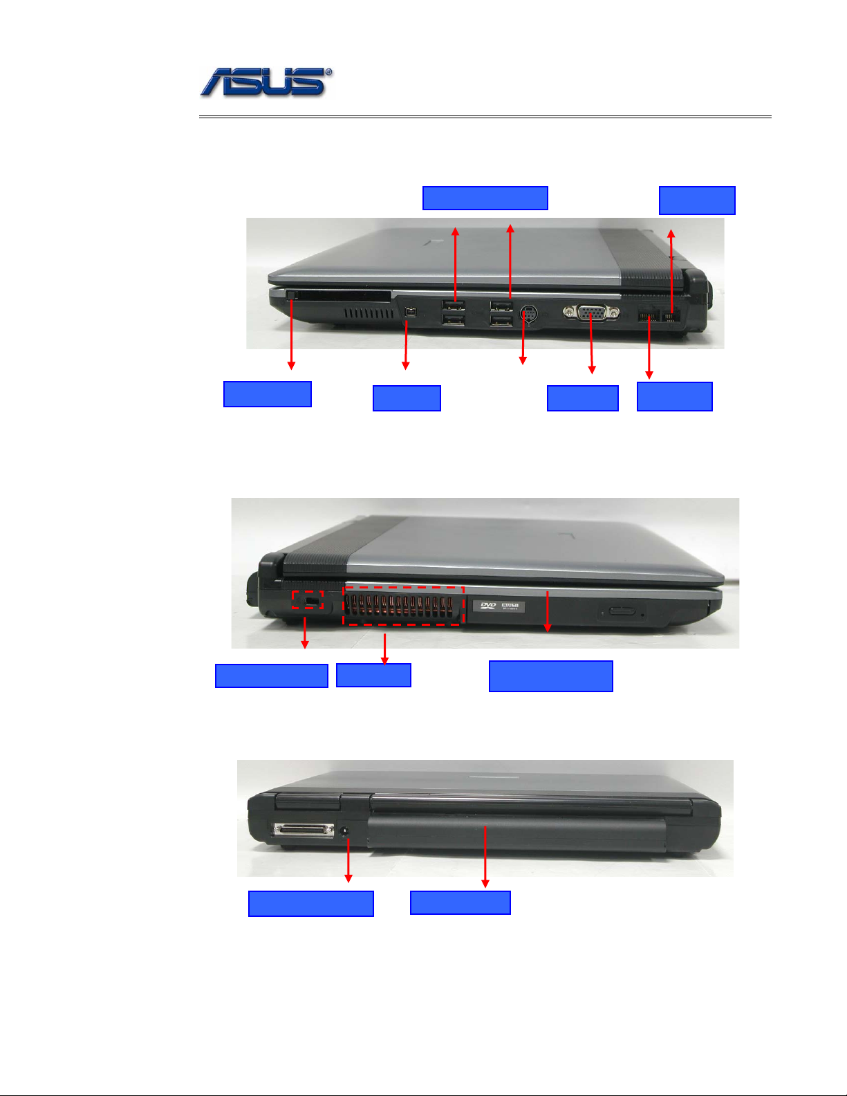
)
p
USB (2.0
orts
Modem port
PCMCIA slot
1394 port
VGA Port
LAN port
Kensington Lock
Air vents
Optical Drive Device
DC Power Input Jack
Battery Module
1 - 3
service overview
COMPONENTS
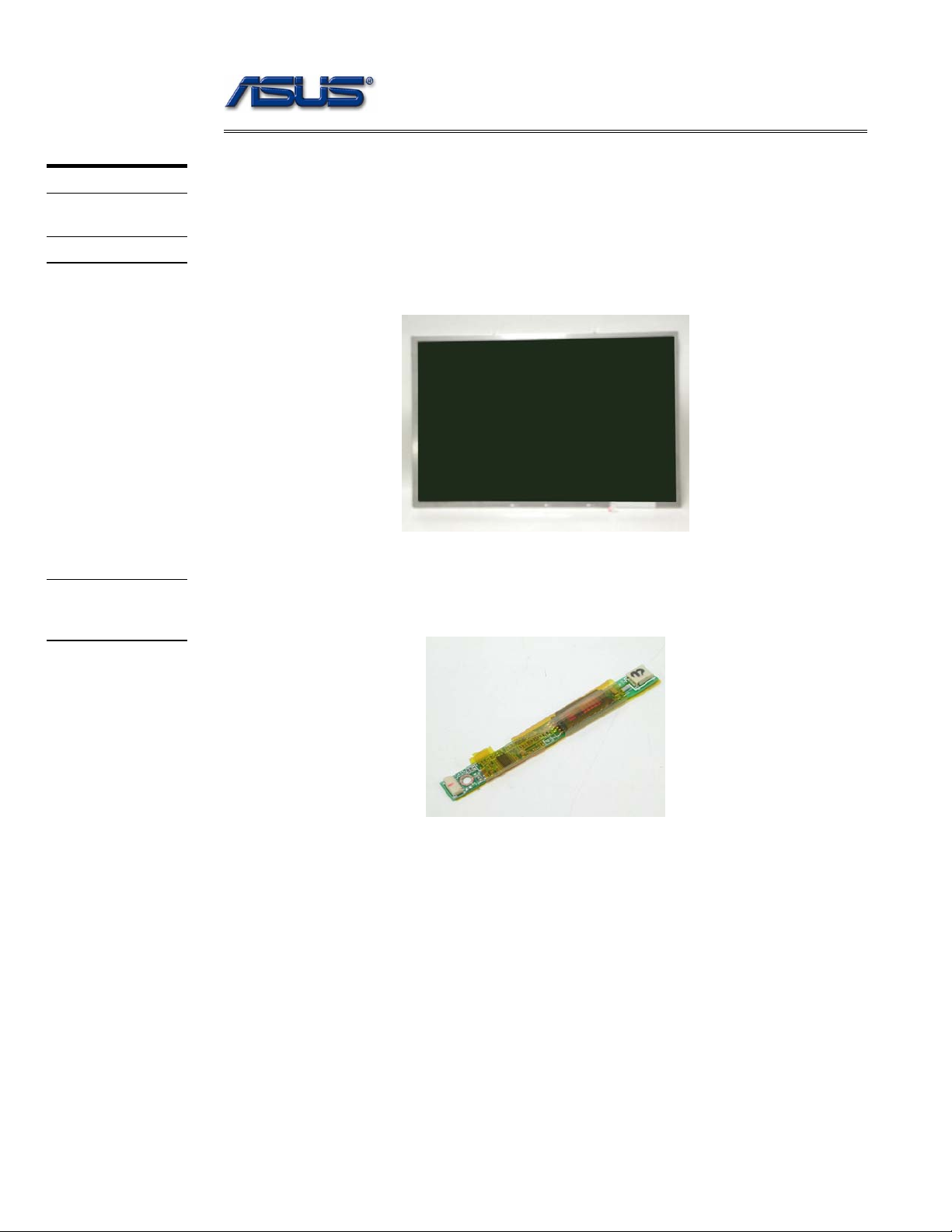
LCD
INVERTER
BOARD
Components
The illustrations below show the components of the S62 Series.
LCD Panel*
The illustration below shows the LCD display panel. The S62 Series notebook comes with
15.0” TFT LCD Panel.
Inverter Board
The illustration below shows the inverter board, which is hidden underneath the lower edge
of the LCD front bezel.
1 - 4
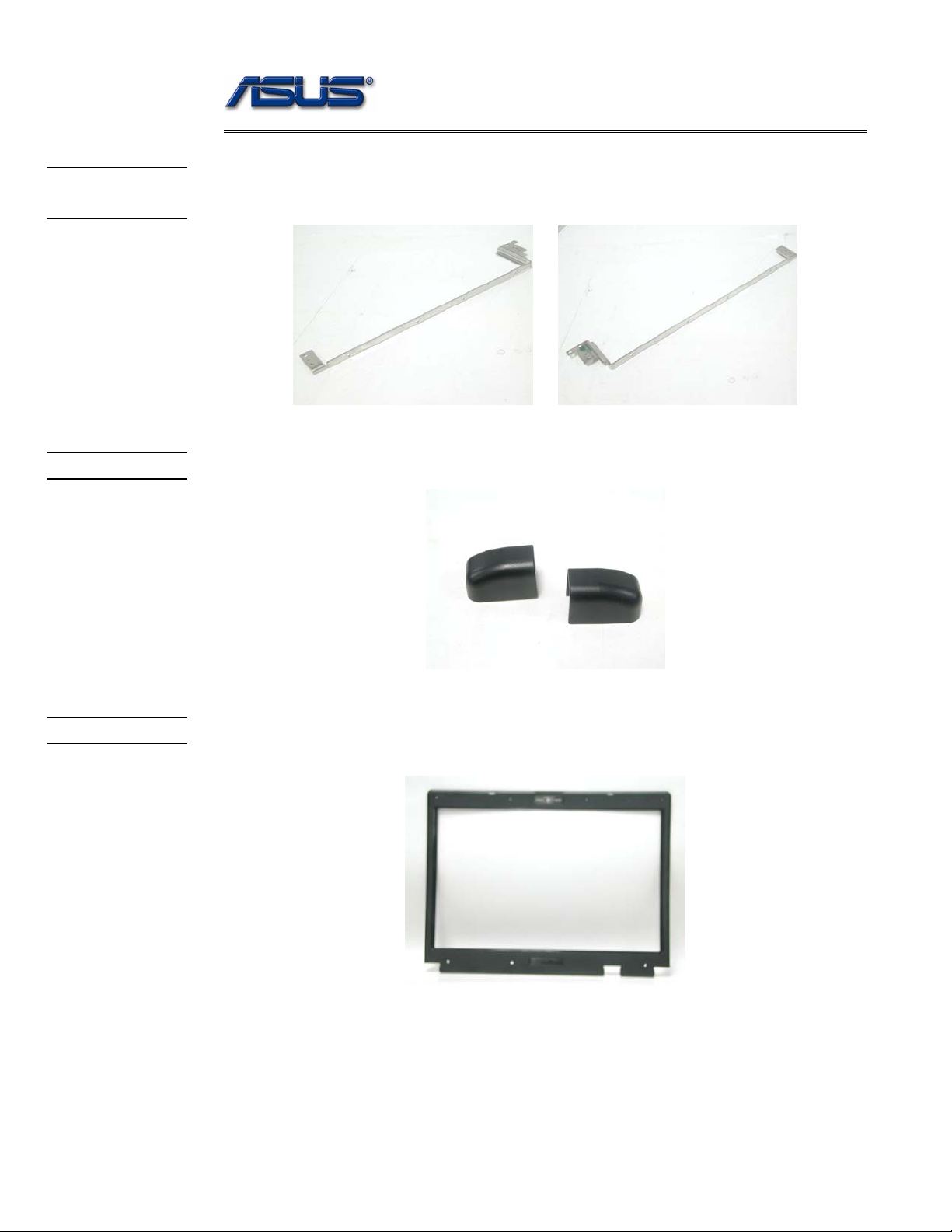
LCD
BRACKETS
HINGE COVER
service overview
LCD bracket
The illustration below shows the LCD brackets.
Hinge Cover
The illustration below shows the Hinge Cover.
LCD CASE
LCD Case
The illustration below shows the LCD case. Here is the LCD bezel.
1 - 5
service overview
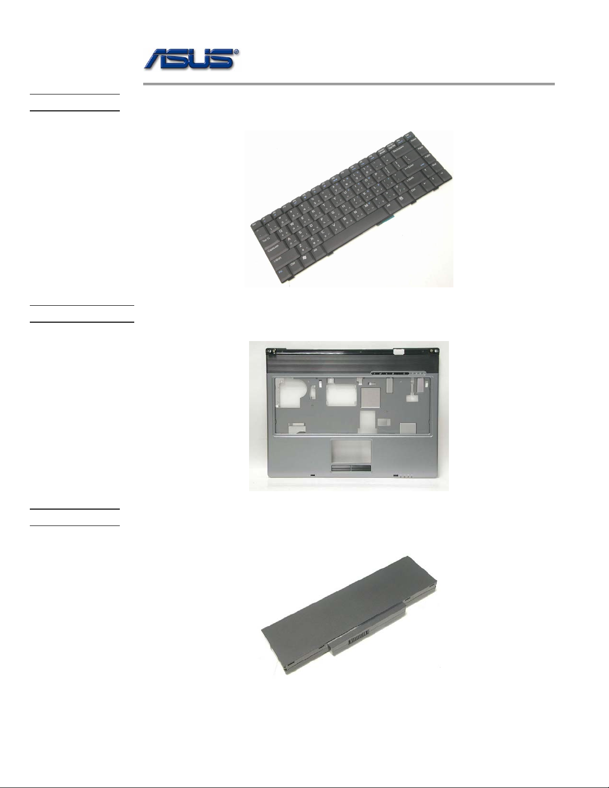
KEYBOARD
TOP CASE
Keyboard
The illustration below shows the keyboard plate. It can be exchanged with keyboard plates
with different language layouts, such as U.S., German, Russian, British, Italian and others.
Top Case Module
The illustration below shows the top case of the notebook.
BATTERY
Battery Pack
The illustration below shows the battery pack of the notebook. It’s located at bottom of the
notebook.
1 - 6
service overview
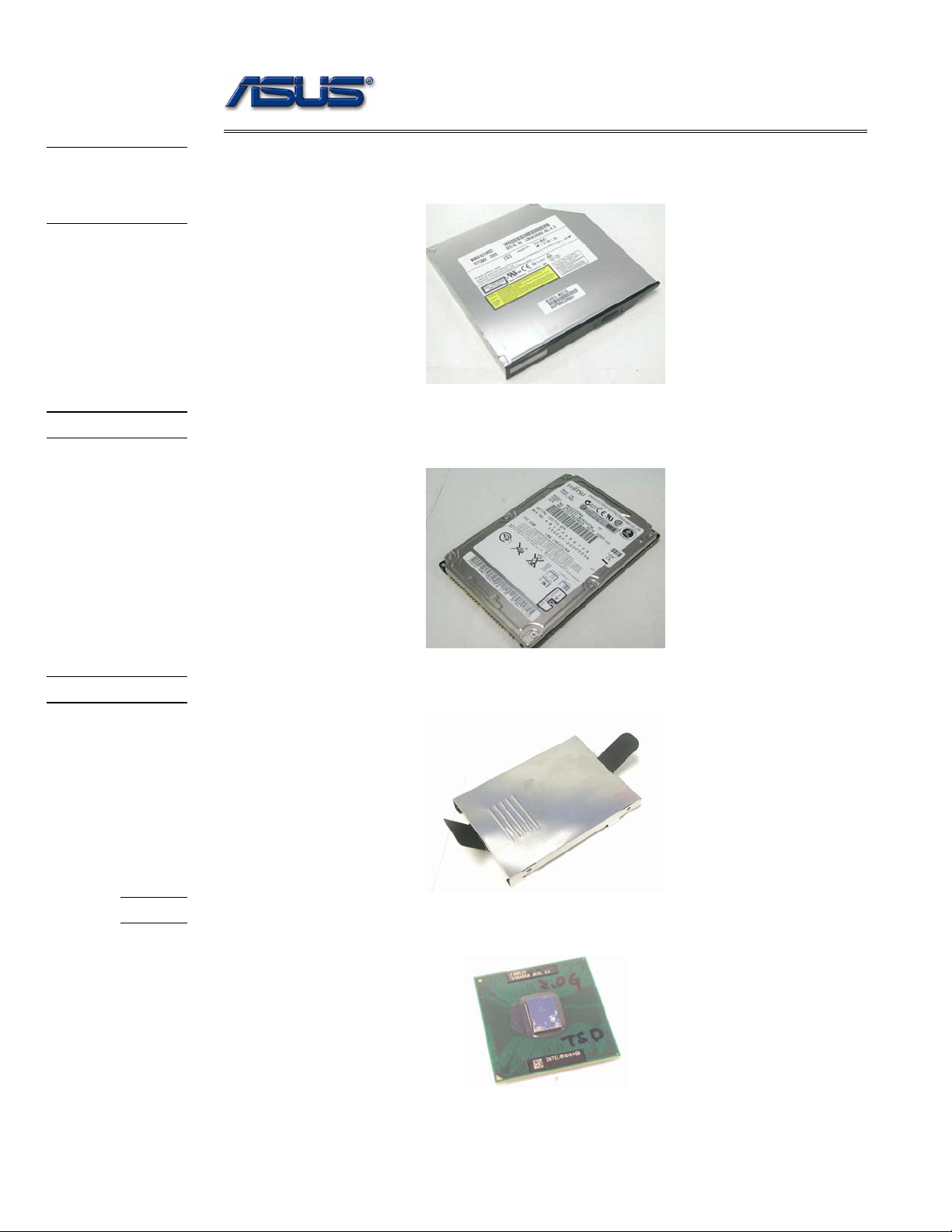
OPTICAL
DRIVE
DEVICE
HDD
Optical Drive Device
The illustration below shows the Optical Drive Device
Hard Disk Drive
The illustration below shows the 2.5” industry-standard HDD with 9.5mm height.
HDD BRACKET
CPU
HDD Bracket
The illustration below shows the HDD Bracket that is placed over the HDD.
CPU
The illustration below shows the Intel Pentium-M CPU view.
1 - 7
service overview
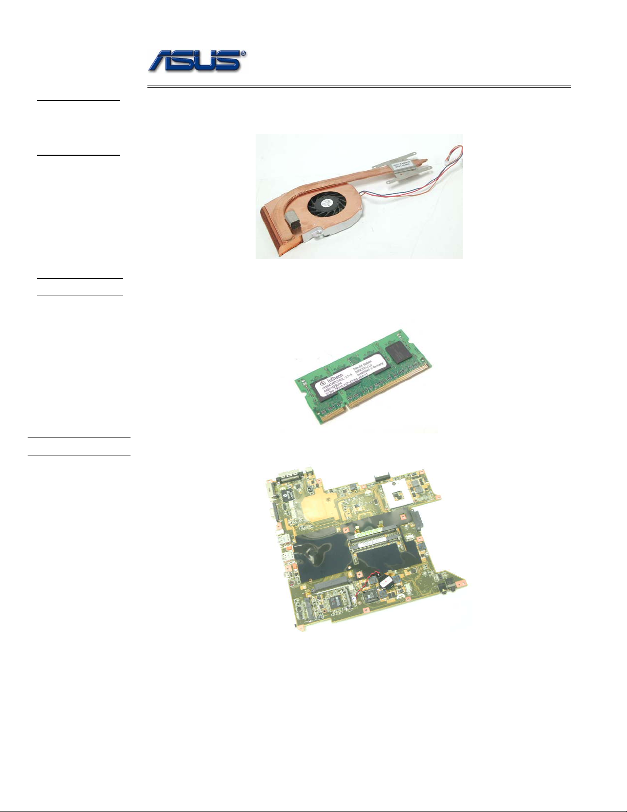
CPU
THERMAL
MODULE
MEMORY
CPU Thermal Module
The illustration below shows the thermal module for the CPU. It’s located on the top of
CPU.
Memory Module
The illustration below shows the industry-standard 200pin SO-DIMM DDR SDRAM
module for the notebook.
MOTHERBOARD
Motherboard
The illustration below shows the motherboard of the notebook.
1 - 8
MODEM
MODULE
WALN
MODULE
service overview
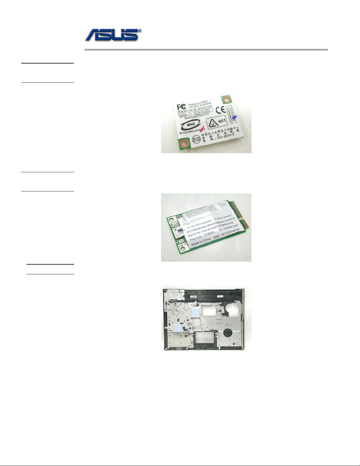
Modem Module
The illustration below shows the modem module of the notebook.
WALN Module
The illustration below shows the WALN module of the notebook.
TOP CASE
Top Case
The illustration below shows the TOP case of the notebook.
1 - 9
service overview
Service Overview
Please pay special attention to the cautions below to prevent any damages to the notebook
and also please be sure to select the appropriate tools described in this section to perform any
services desired.
CAUTIONS
Precautions
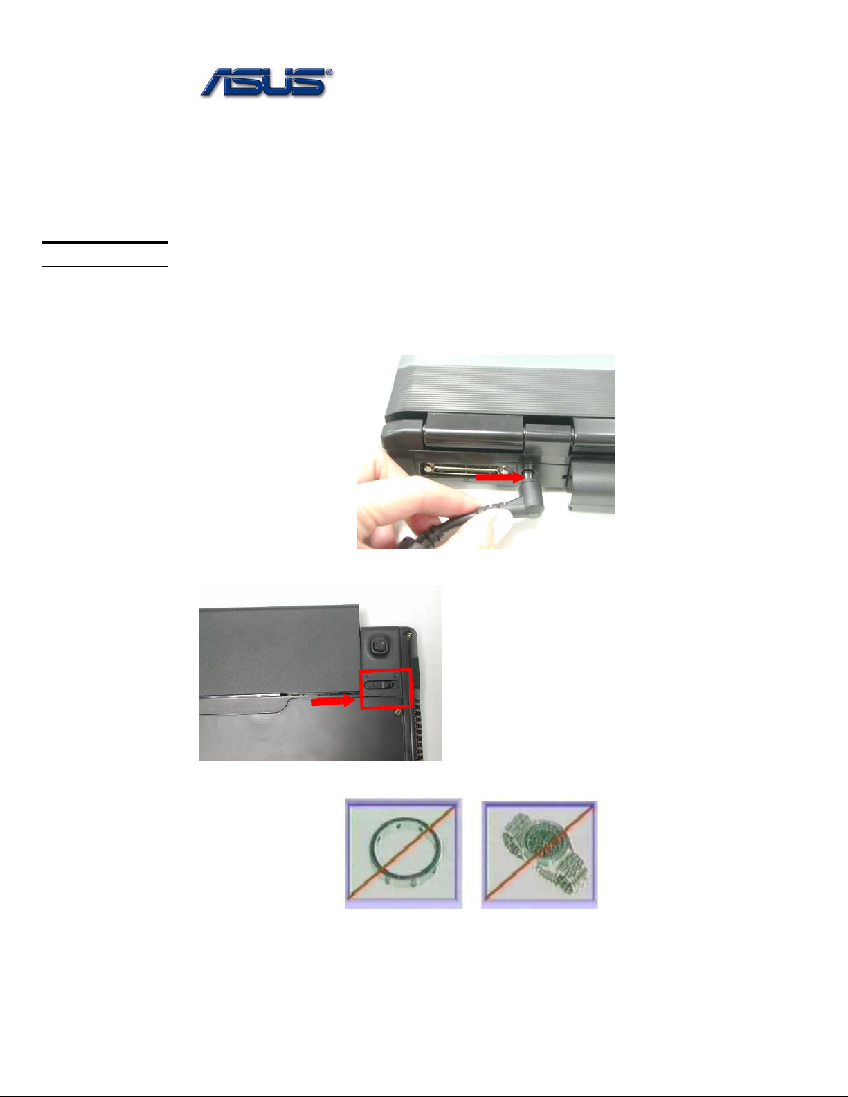
Before you perform any service and/or repair on the notebook, please follow the steps below
first.
1. Be sure that the notebook is powered down.
2. Disconnect the AC plug from the notebook
3. Turn the notebook over. Unlock and hold the latches, and remove the battery .
3. Remove all rings, watches and any other metal objects from your hands.
4. Always wear a ground strap on your hand to protect the notebook from static discharge.
1 - 10
service overview
TOOLS
CROSS
SCREW-
DRIVER
FLATHEAD
SCREW-
DRIVER
TWEEZERS
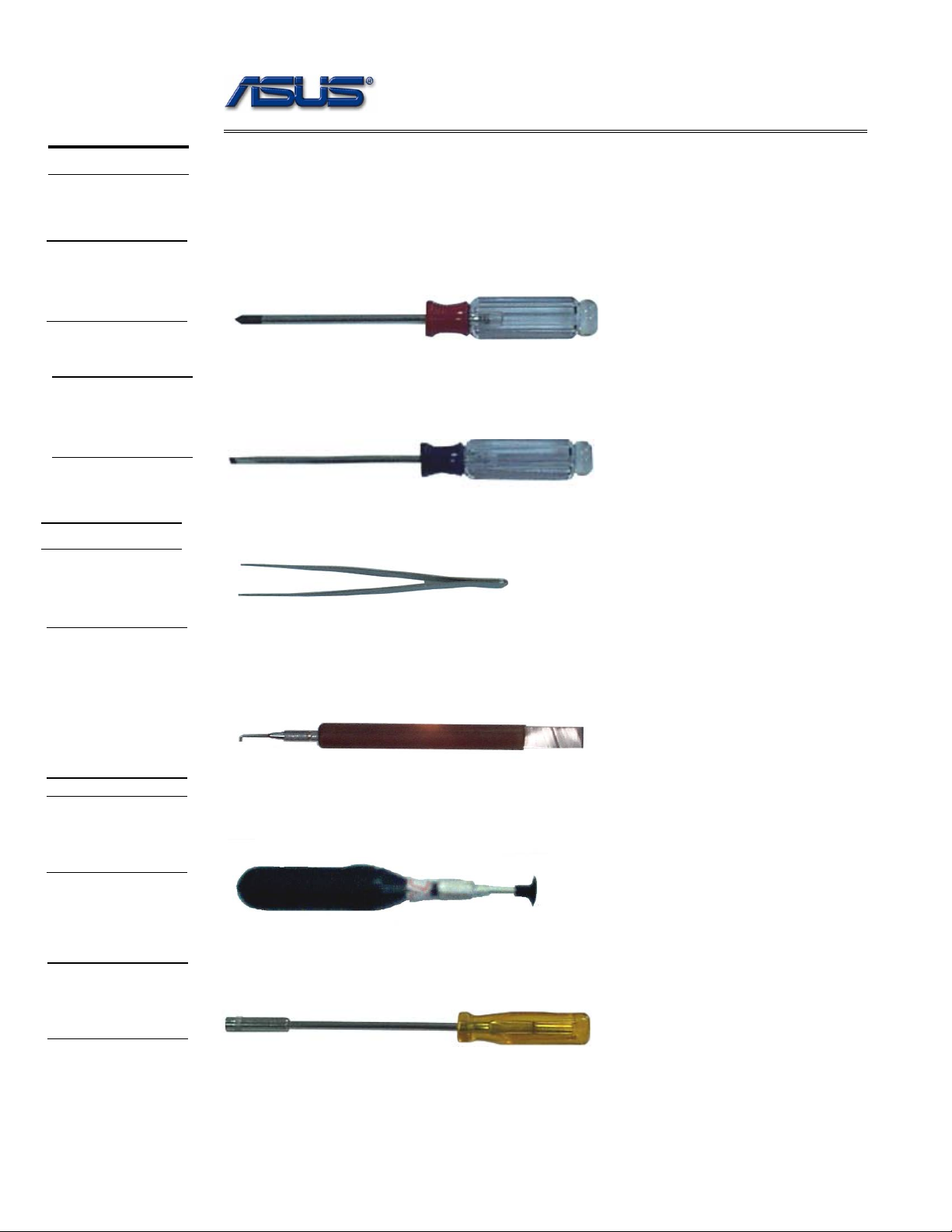
Appropriate T ools
The illustrations below show the appropriate tools that should be used for the notebook’s
service and repair.
Phillips-head Screwdriver
Use a Phillips-head screwdriver to fasten/remove the K- or B-typed screws.
Single-Slotted Screwdriver
Use a single-slotted screwdriver to lock/unlock the flexible cable connector locks
Tweezers
Use a pair of tweezers to remove/insert flexible cables.
INSERTION
AND
EXTRACTION
TOOL FOR
FPC
CONNECTOR
VACUUM
HANDLING
TOOL
SPACER
SCREW-
DRIVER
Insertion and extraction tool for FPC connector
Use insertion and extraction tool for FPC connector to handle locking and unlocking of FPC
connectors.
Vacuum Handling Tool
Use Vacuum handling tool to handle CPU.
Spacer Screwdriver
Use a spacer screwdriver to fasten/remove spacer screws or hex screws.
1 - 11
Disassembly procedure
A
Chapter
Disassembly Procedure
Please follow the information provided in this section to perform the complete
disassembly procedure of the notebook. Be sure to use proper tools
described before.
SUS S62 Series Notebook consists of various modules. This chapter describes the
procedures for the complete notebook disassembly. In addition, in between procedures,
the detailed disassembly procedure of individual modules will be provided for your
service needs.
The disassembly procedure consists of the following steps:
• Battery Module
• HDD Module
• Wireless Module
• Memory Module
• CPU Module
• ODD Module
• Keyboard
• Top Case Module
• Motherboard
• Bottom case Module
• LCD Module
Disassembly procedure
BATTERY
BATTERY
MODULE
REMOVAL
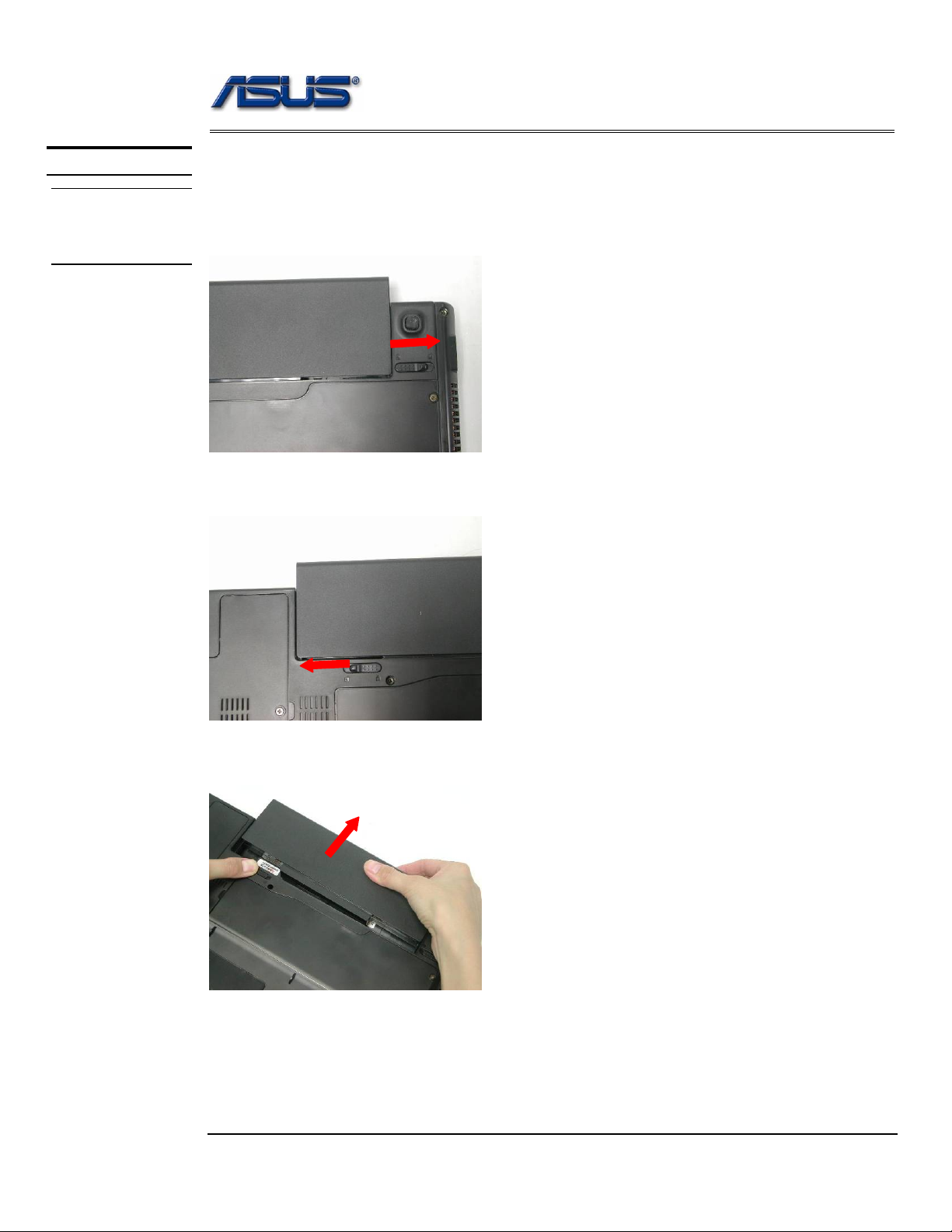
Battery Module
The illustration below shows how to remove the battery module.
1. Unlock and hold the latch No (1).
1
2. Slide the battery lock (No.2) and pull the battery pack out.
2
3. Pull the battery pack out.
Disassembly procedure
HDD
MODULE
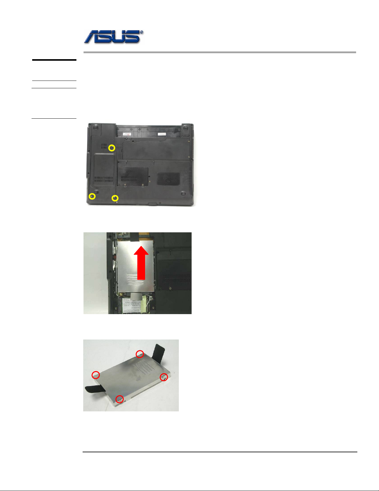
HDD Module
The illustrations below show how to remove the HDD module from the notebook.
HDD
MODULE
REMOVAL
Removing HDD Module
1. Remove 3 screws (M2.5*4L (K)), then remove the HDD door.
M2.5*4L
2. Lift the HDD module and then remove it.
3. Remove 4 screws [M3 * 4(L)] to separate HDD from HDD housing.
M3*4L
Disassembly procedure
WIRELESS
LAN
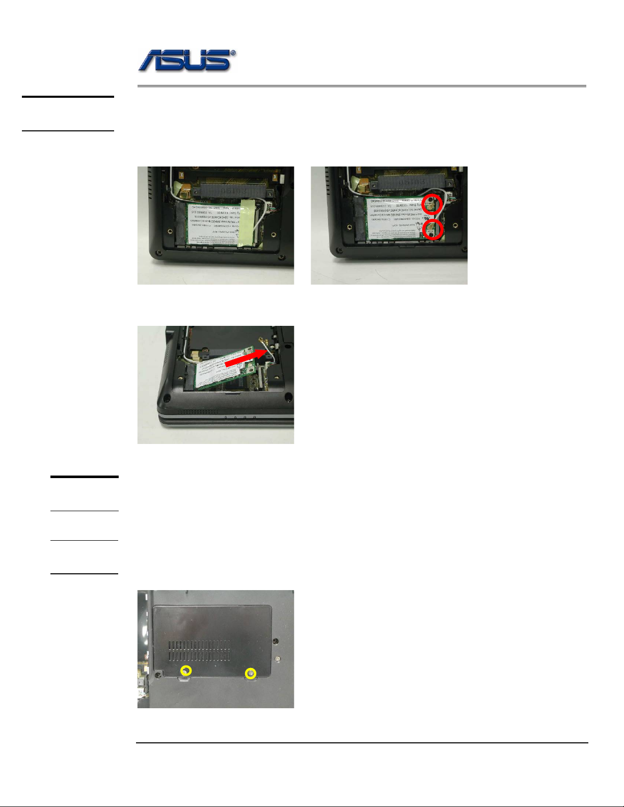
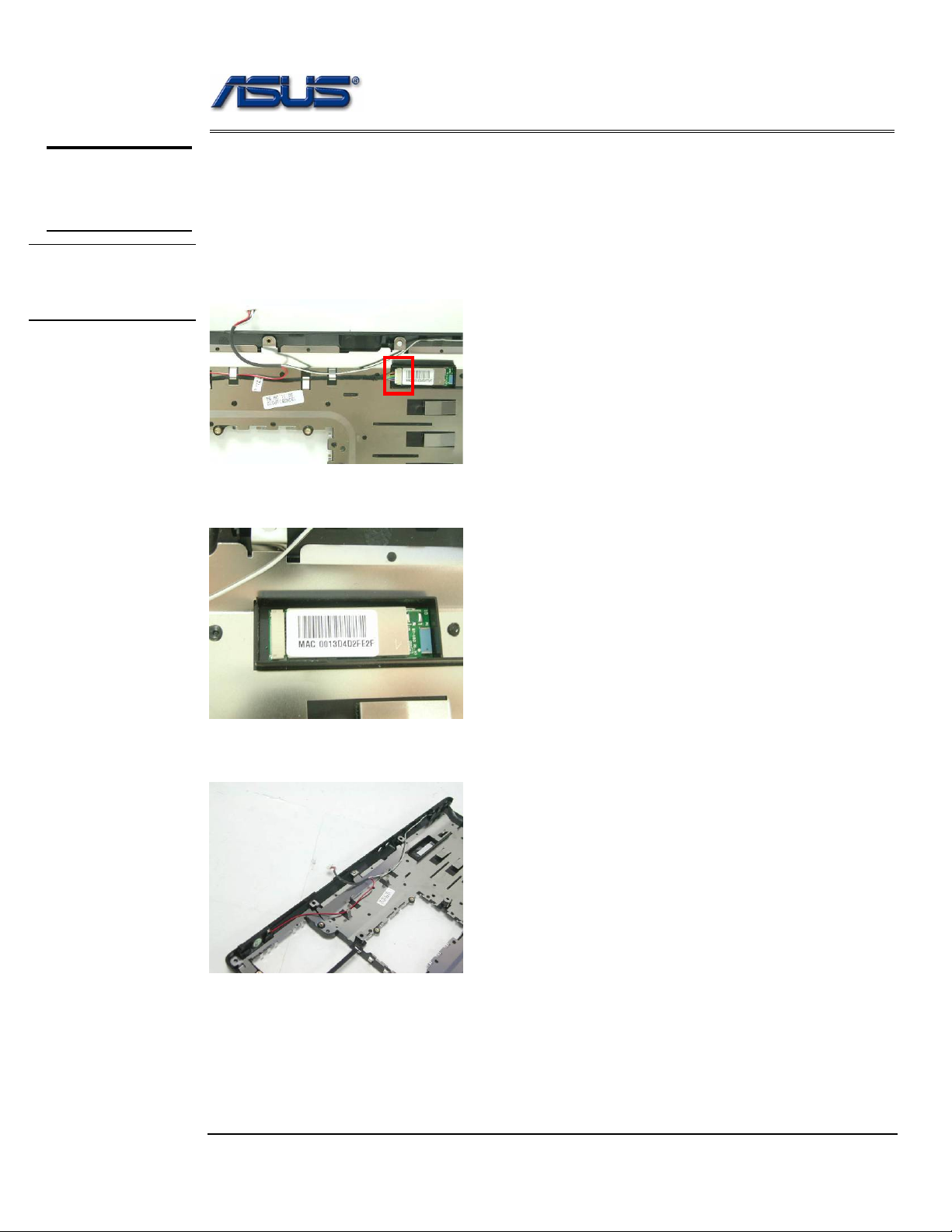
Wireless LAN Module
The illustration below shows how to remove the Wireless LAN module.
1. Remove 1 piece of tape and disconnect the MAIN & AUX antenna.
2. And open the two latches to pop the MINI PCI MODULE up then pull it out.
MEMORY
MODULE
Memory Module
The S62 Series Notebook does not have RAM onboard. There is one SO-DIMM
sockets for installing SO-DIMM RAM. It can upgrade the total memory size up to 1GB .
MEMORY
REMOVAL
Removing Memory module
1. Remove 2 screws (M2.5*4L (K)), then remove the DIMM door.
M2.5*4L
Disassembly procedure
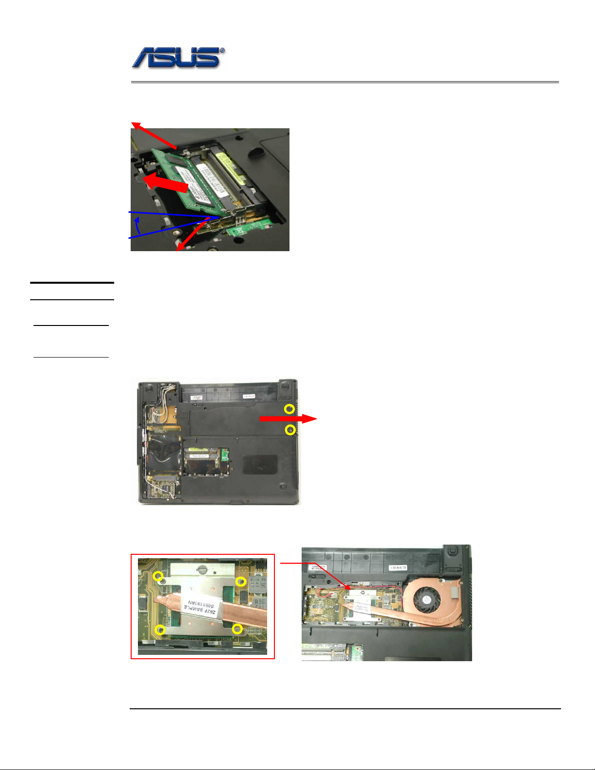
2. Open the 2 latches aside (No. 1, 2), which will pop the memory module up to an
angle of 30°, then pull out the memory module in that angle (No. 3).
1
CPU MODULE
CPU
REMOVAL
3
2
o
30
CPU Module
The illustrations below show how to remove the CPU module from the notebook.
Removing CPU Module
1. Remove 2 screws (M2.5*4L (K)), then remove the CPU door.
M2.5*4L
2. Remove 4 screws (M2*3L (K)) by order.
3
M2*3L
1
2
4
Disassembly procedure
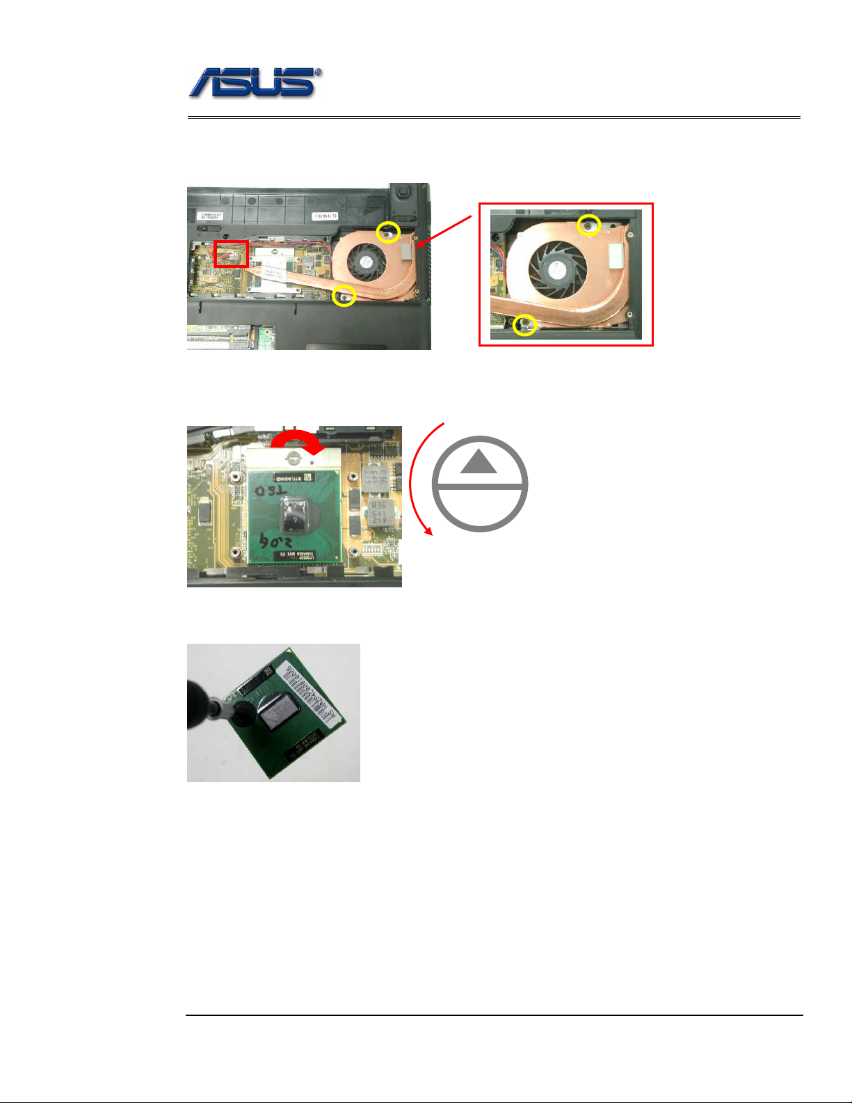
3. Disconnect the Fan cable and remove 2 screws (M2.5*4L (K)) then take away the
CPU thermal module.
M2.5*4L
4. Turn the non-removable screw here 180 degrees counter-clockwise to loosen the
CPU.
L
O
Unlock
5. Squeeze the vacuum handling pump and use it to lift the CPU away.
Disassembly procedure
OPTICAL
DRIVE
DEVICE
ODD
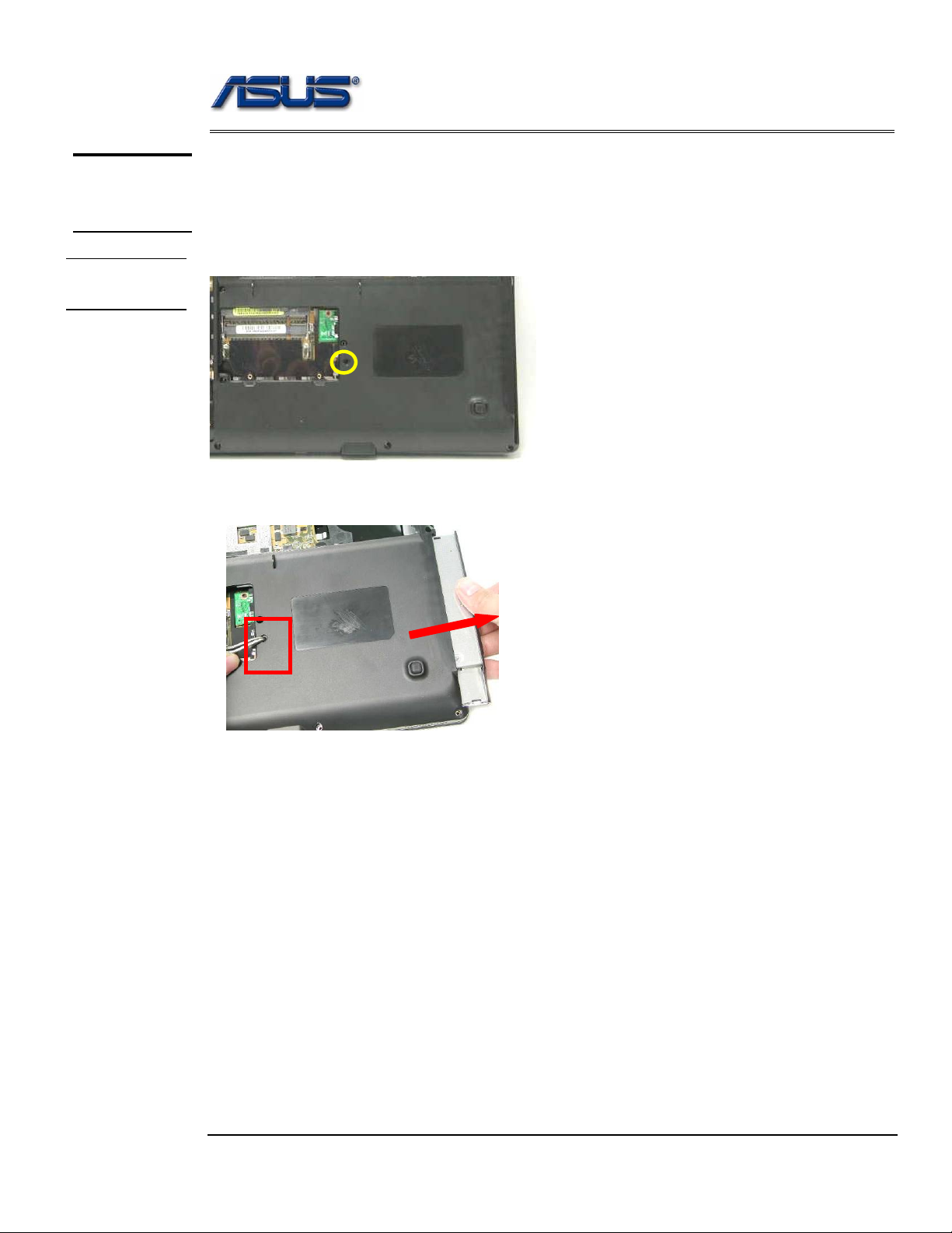
ODD Module
The illustration below shows how to remove the ODD module.
1. Remove 1 screw (M2.5*4L (K)).
REMOVAL
M2.5*4L
2. Push the ODD Module out by a pair of tweezers.
Disassembly procedure
3
KEYBOARD
K/B REMOVAL
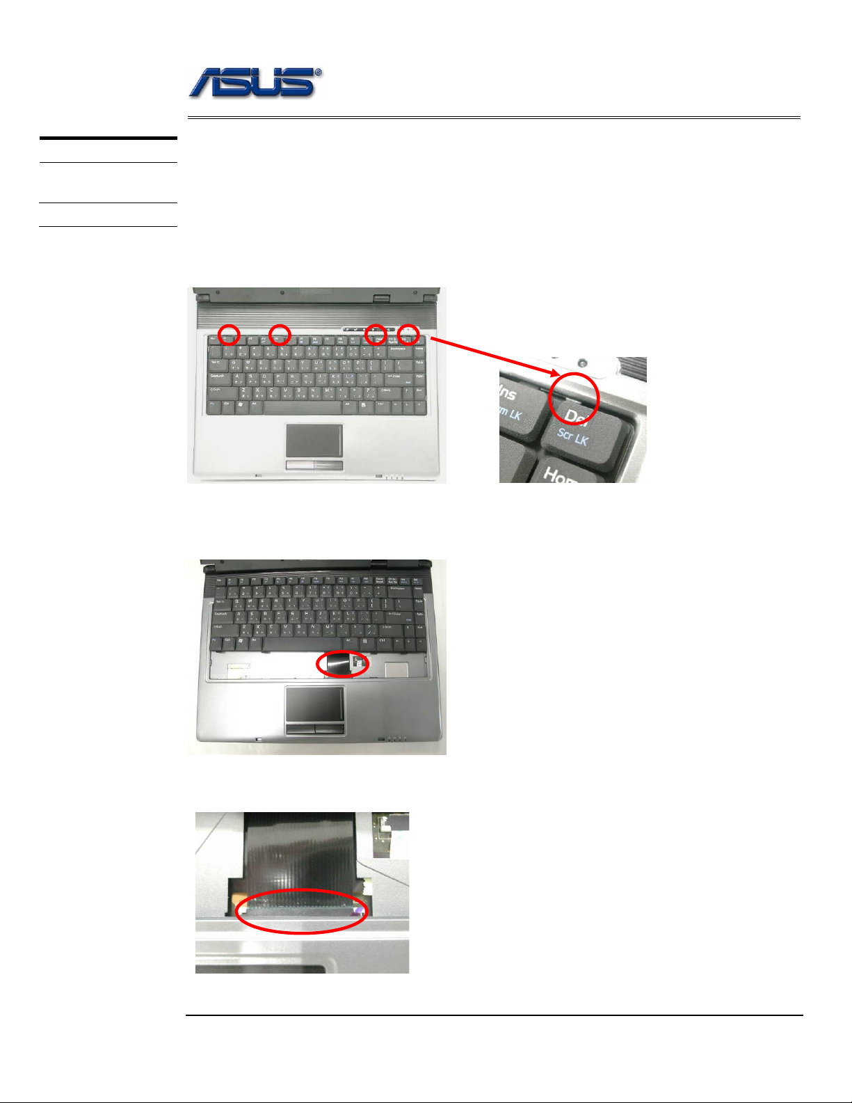
Keyboard
The illustration of below shows how to remove the keyboard.
Removing Keyboard
1. Push the 4 latches in (No.1, No.2, No.3, No.4) with a pair of tweezers or a
single-slotted screwdriver and lift the keyboard plate up.
2 1 4
2. Lay the keyboard down over the Top case. *Do not remove the keyboard yet.
The keyboard cable is still attached.
3. Disconnect the FPC connector by a pair of tweezers.
Disassembly procedure
CABLE
REMOVAL
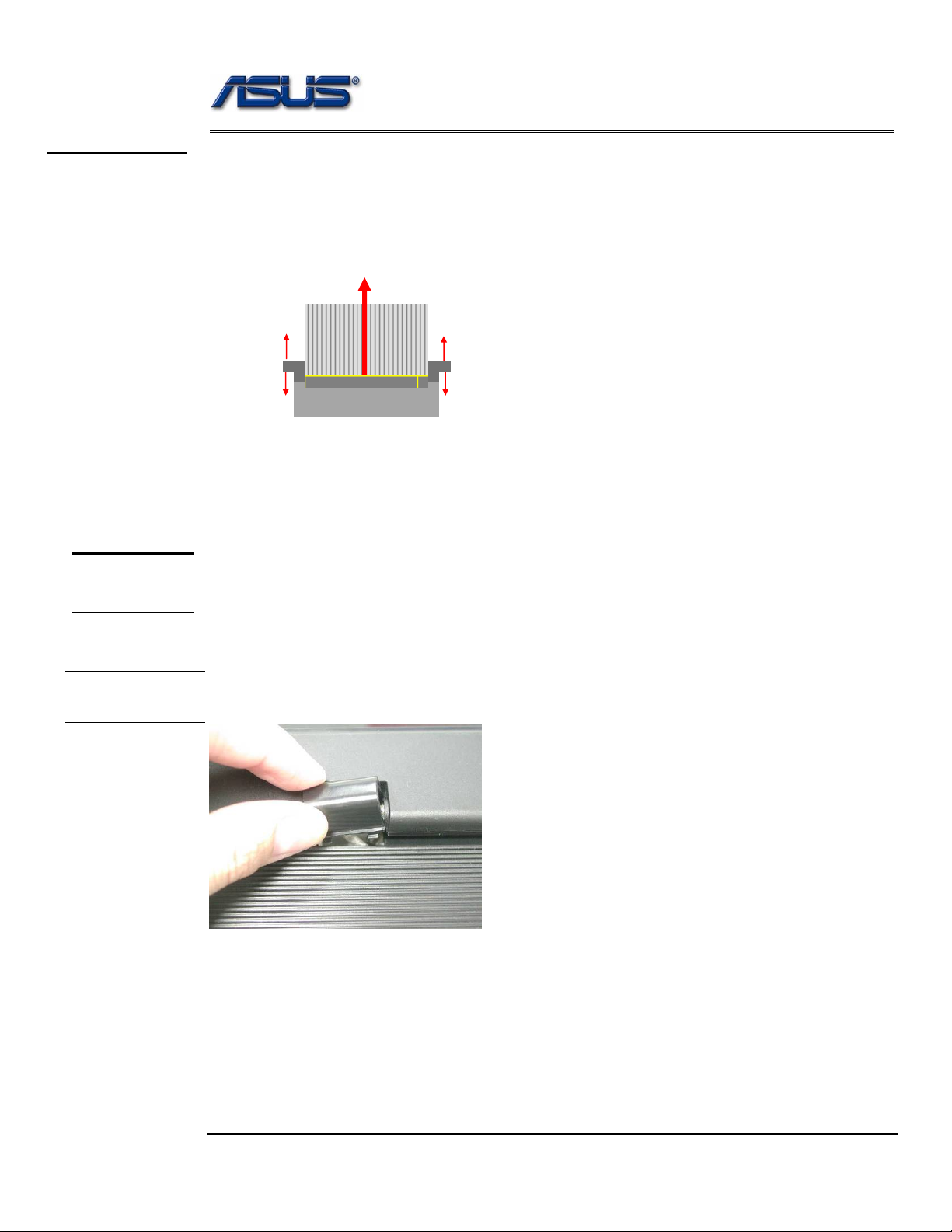
Removing Keyboard Cable
1. Use a flexible connector tool to unlock the cable connector on both ends (no. 1).
2. Carefully pull out the keyboard cable (no. 2) with a pair of tweezers.
3. Lock the connector (no. 3) again to avoid possible breakage.
2. Cable out
1. Unlock
3.
1. Unlock
3.
4. Remove keyboard from the top case.
TOP CASE
MODULE
T op Case Module
The illustrations below show how to disassemble and remove the top case module of the notebook.
The module contains the top case itself.
HINGE COVER
REMOVAL
Removing top Case Module
1. Remove the MIDDLE cover.
Disassembly procedure
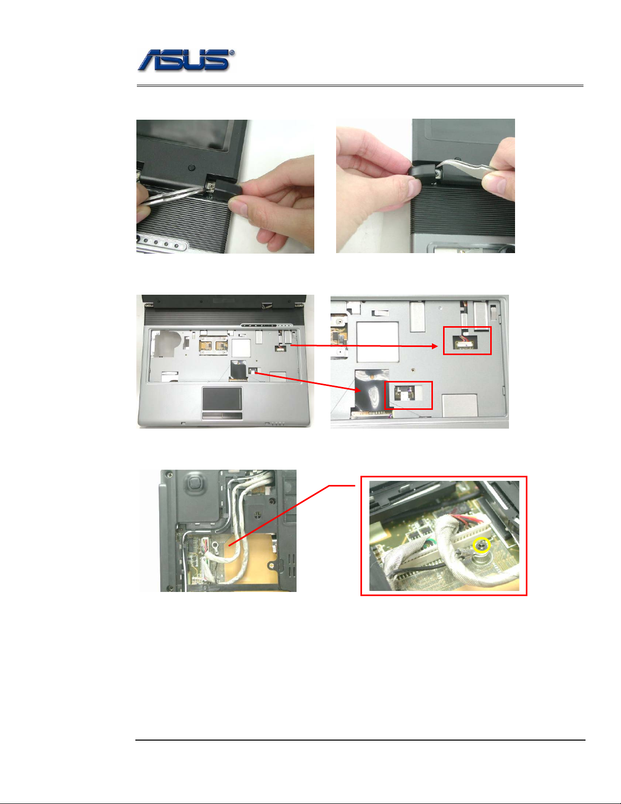
2. Use a pair of tweezers to remove both hinge Cover.
3. Disconnect the LANCH cable and touchpad FFC on the top case.
LANCH cable
Touchpad FFC
4. Turn over the NB and remove 1 screws (M2*3L (K)).
I
M2*3L
Disassembly procedure
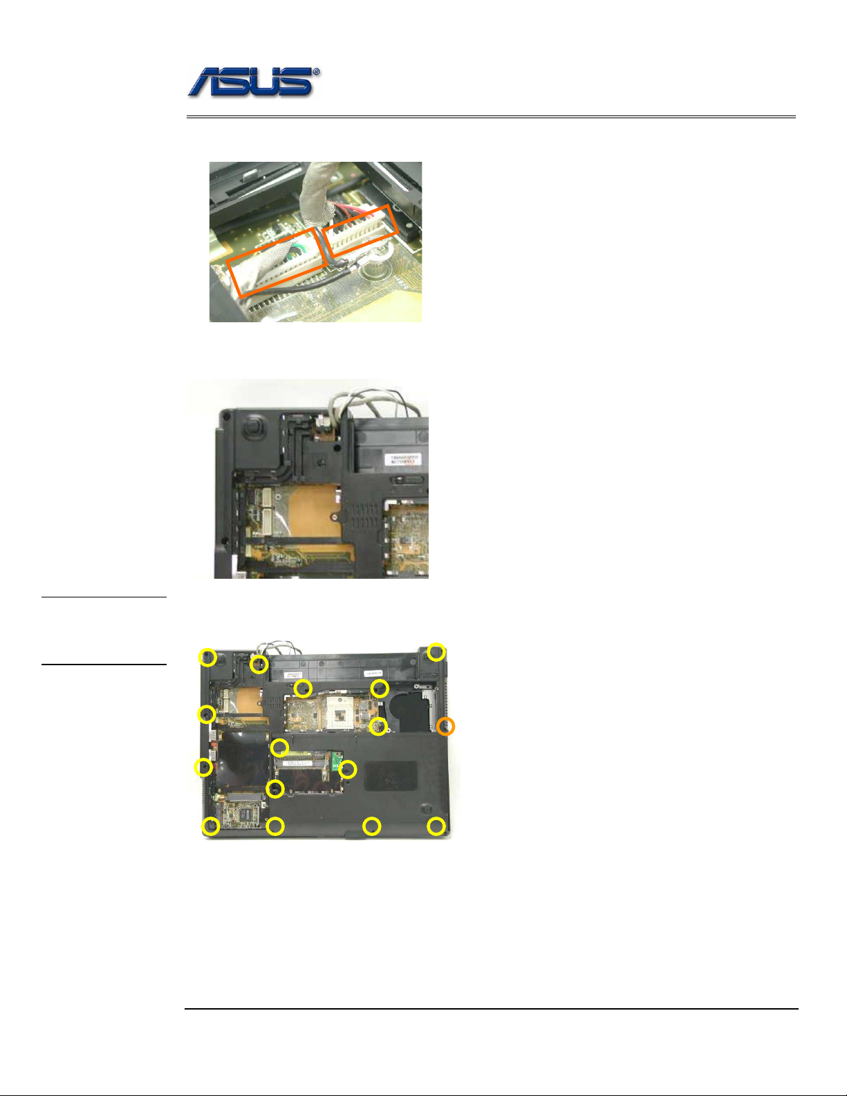
5. Disconnect the Coaxial & inverter cable.
Coaxial cable
Inverter cable
6. Arrange the Coaxial & inverter cable and antenna on the bottom case.
BOTTOM
CASE
REMOVAL
7. Remove 15 screws (M2.5*6L (K)) and 1 screw (M2.5*4L) (K)) on the bottom case.
M2.5*4L
M2.5*6L
Disassembly procedure
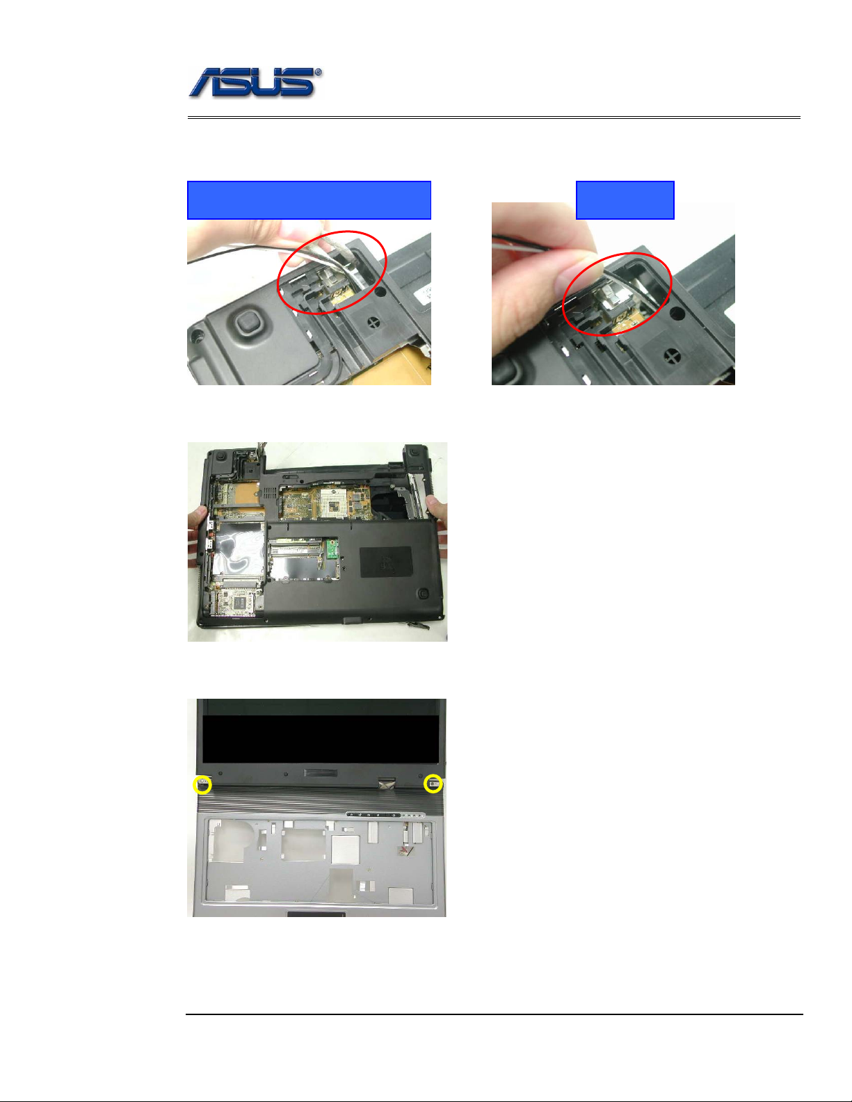
8. Before separate the bottom case, remove a little bit bottom case and let the cable
and antennas through out of hole.
Inverter & camera cable
Antenna
9. Separate the bottom case from the top case.
10. Remove 2 screws (M2.5*6L (K)) on both hinge.
M2.5*6L
TOP
CASE
REMOVAL
Disassembly procedure
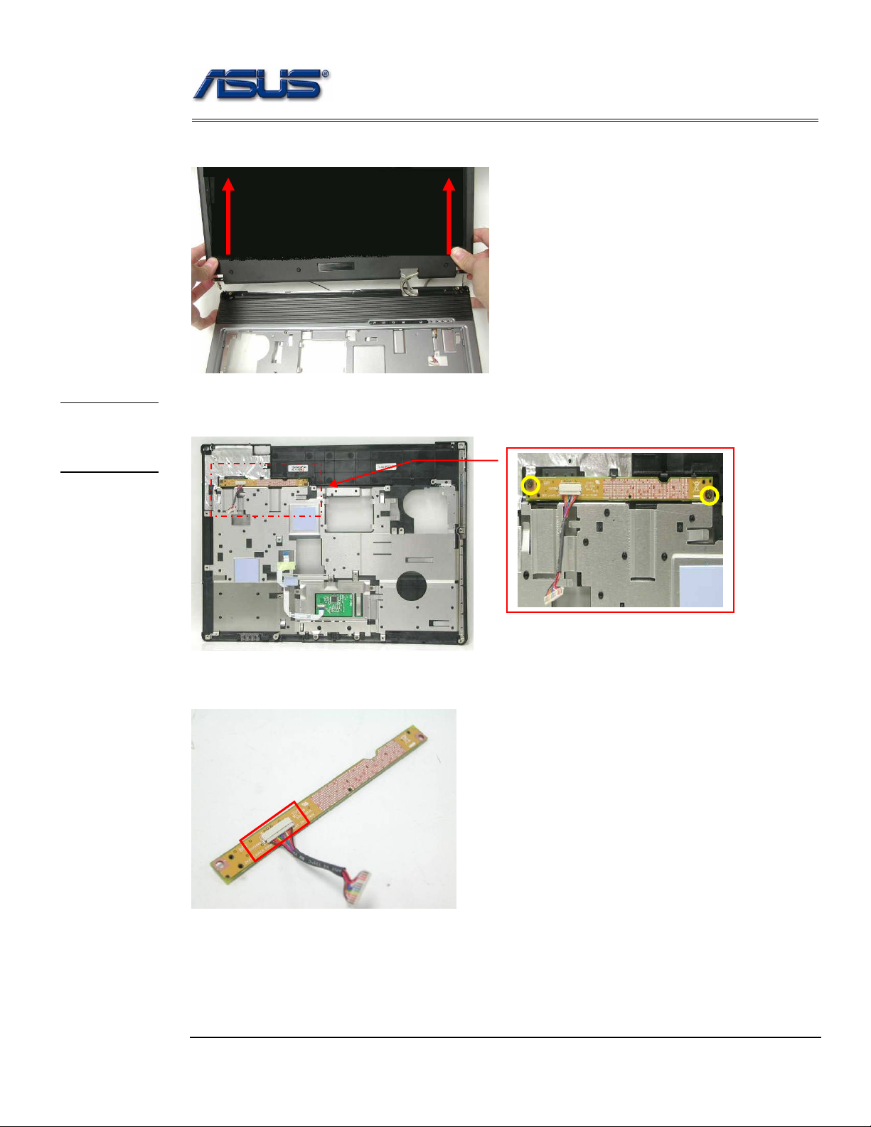
11. Separate the LCD module from the Top Case module
12. Remove 2 screws (M2.5*4L (K)) and take away the LANCH board.
13. Remove the LANCH board cable.
M2.5*4L
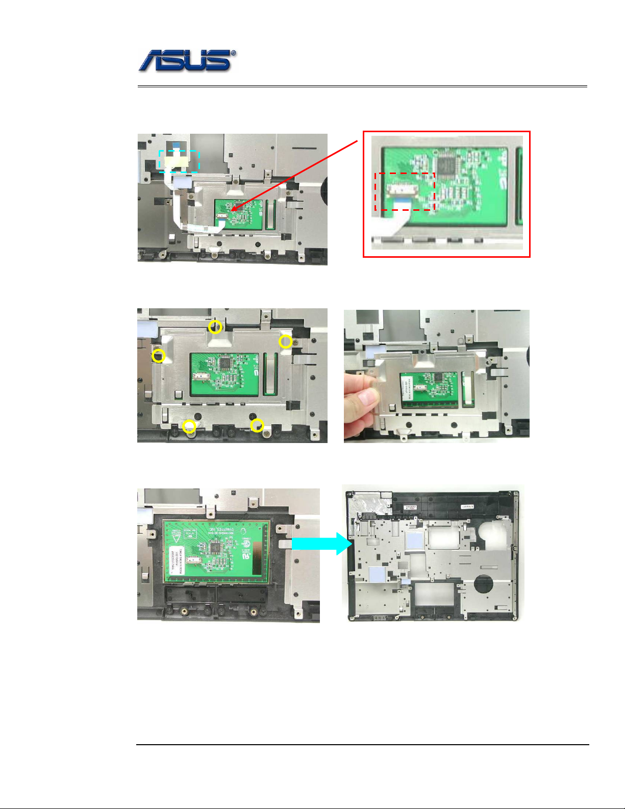
Disassembly procedure
14. Disconnect the touch pad FFC and remove 1 piece of tape then take away the
touch pad FFC.
15. Remove 5 screws (M2.5*4L (K)) and take away the touchpad bracket.
M2.5*4L
16. Take away the touchpad.
Disassembly procedure
MOTHERBOARD
MOTHERBOARD
REMOVAL
Motherboard
The illustrations below show how to disassemble and remove the Motherboard.
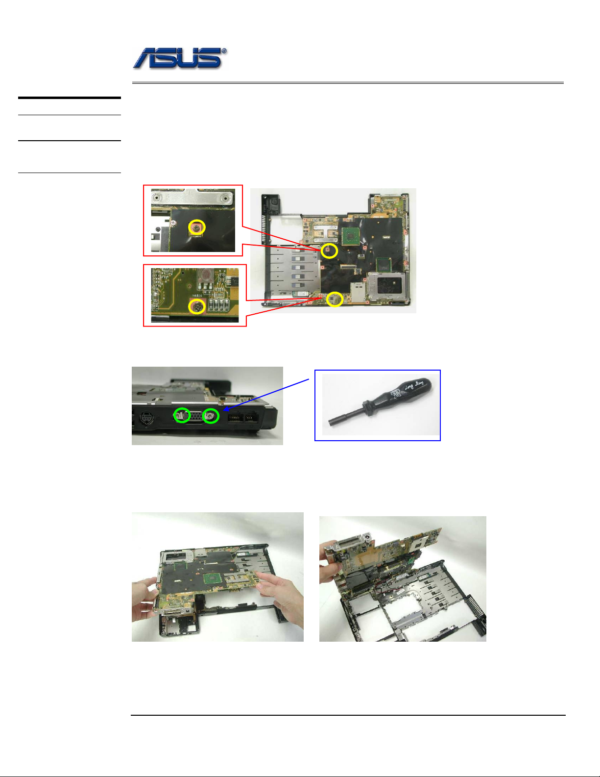
Removing Motherboard
1. Remove 2 screws (M2.5*4L (K)).
2. Remove 2 screws for CRT on the right side by a spacer screwdriver.
3. Separate the Motherboard from the bottom case. *Do not remove the
Motherboard yet. The Bluetooth & Speaker cables are still attached.
Disassembly procedure
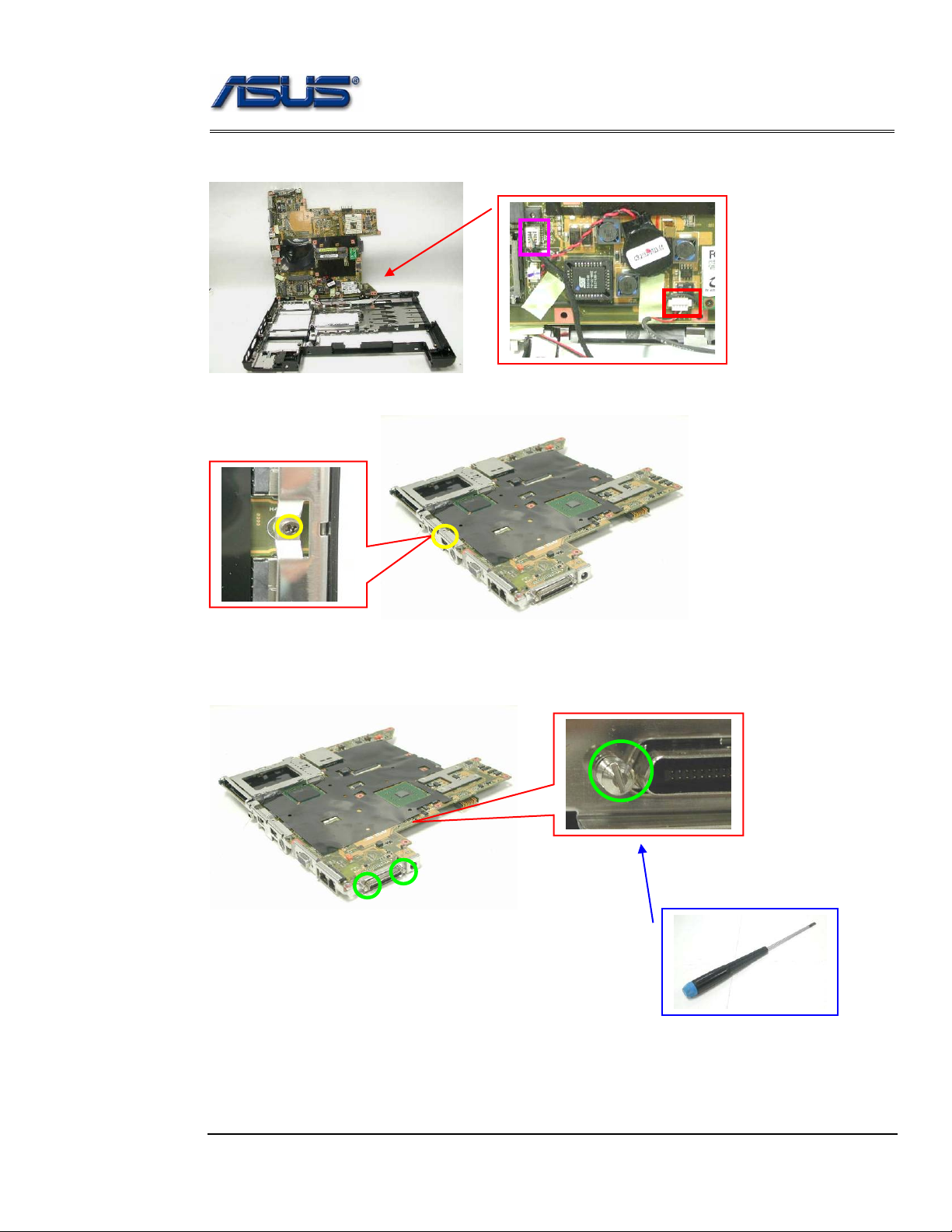
4. Disconnect the Bluetooth & Speaker cables then take away the Motherboard.
Bluetooth cable
Speaker cable
5. Remove 1 screw (M2*3L (K)) on the IO bracket.
M2*3L
6. Use a single-slotted screwdriver to remove 2 screws HEX 5mm then take away the
IO bracket.
Disassembly procedure
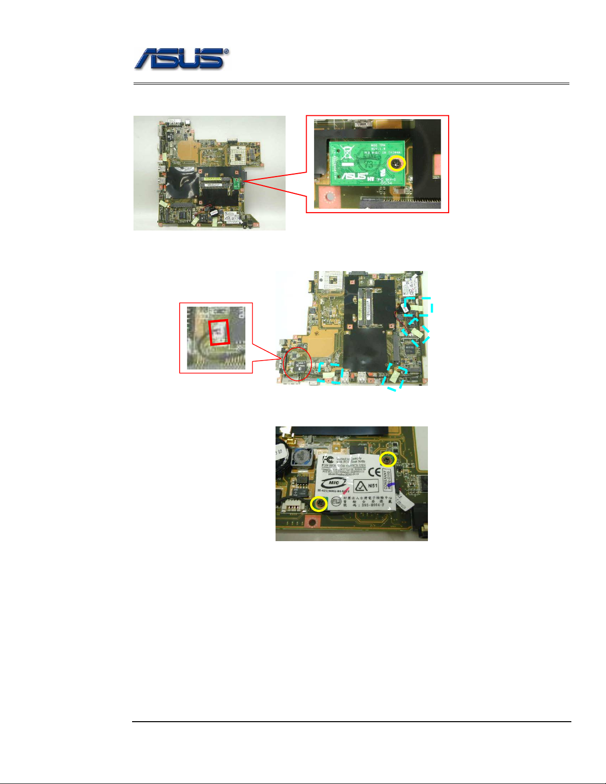
7. Remove 1 screw (M2*3L (K)) and take away the TPM board .
M2*3L
8. Remove 4 pieces of tapes and disconnect the modem cable.
9. Remove 2 screws (M2*3L (K)) and take away the modem board.
M2*3L
Disassembly procedure
BOTTOM
CASE
MODULE
BOTTOM
CASE
DISASSEMBLY
Bottom Case Module
The illustrations below show how to remove and disassemble the Bottom case module.
The module contains Bluetooth board, speaker cable.
Disassembling Bottom case Module
1. Disconnect the Bluetooth cable and remove it.
2. Take away the Bluetooth board from the bottom case.
3. Take away the speaker module from the bottom case.
Disassembly procedure
LCD MODULE
LCD MODULE
DISASSEMBLY
LCD Module
The illustrations below show how to remove and disassemble the LCD module. The
module contains LCD panel, Inverter board, LCD bezel, LCD back cover.
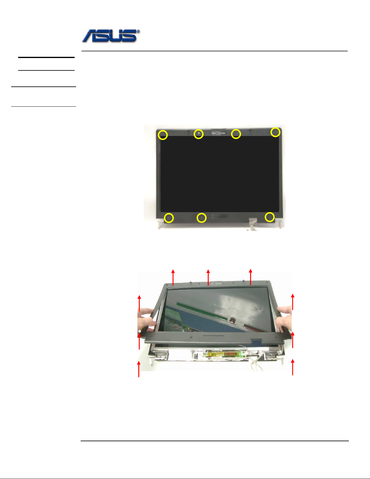
Disassembling LCD Module
4. Remove 7 rubber pads and 7 screws (M2.5 x 6L) from LCD module.
M2.5*6L
5. Prying the inside edges of the LCD bezel, and then separates it from LCD back
cover.
Loading...