

Page 1

ROG
STRIX Z370-F
GAMING
Motherboard
Page 2

E13351
First Edition
August 2017
Copyright© 2017 ASUSTeK COMPUTER INC. All Rights Reserved.
No part of this manual, including the products and software described in it, may be reproduced,
transmitted, transcribed, stored in a retrieval system, or translated into any language in any form or by any
means, except documentation kept by the purchaser for backup purposes, without the express written
permission of ASUSTeK COMPUTER INC. (“ASUS”).
Product warranty or service will not be extended if: (1) the product is repaired, modied or altered, unless
such repair, modication of alteration is authorized in writing by ASUS; or (2) the serial number of the
product is defaced or missing.
ASUS PROVIDES THIS MANUAL “AS IS” WITHOUT WARRANTY OF ANY KIND, EITHER EXPRESS
OR IMPLIED, INCLUDING BUT NOT LIMITED TO THE IMPLIED WARRANTIES OR CONDITIONS OF
MERCHANTABILITY OR FITNESS FOR A PARTICULAR PURPOSE. IN NO EVENT SHALL ASUS, ITS
DIRECTORS, OFFICERS, EMPLOYEES OR AGENTS BE LIABLE FOR ANY INDIRECT, SPECIAL,
INCIDENTAL, OR CONSEQUENTIAL DAMAGES (INCLUDING DAMAGES FOR LOSS OF PROFITS,
LOSS OF BUSINESS, LOSS OF USE OR DATA, INTERRUPTION OF BUSINESS AND THE LIKE),
EVEN IF ASUS HAS BEEN ADVISED OF THE POSSIBILITY OF SUCH DAMAGES ARISING FROM ANY
DEFECT OR ERROR IN THIS MANUAL OR PRODUCT.
SPECIFICATIONS AND INFORMATION CONTAINED IN THIS MANUAL ARE FURNISHED FOR
INFORMATIONAL USE ONLY, AND ARE SUBJECT TO CHANGE AT ANY TIME WITHOUT NOTICE,
AND SHOULD NOT BE CONSTRUED AS A COMMITMENT BY ASUS. ASUS ASSUMES NO
RESPONSIBILITY OR LIABILITY FOR ANY ERRORS OR INACCURACIES THAT MAY APPEAR IN THIS
MANUAL, INCLUDING THE PRODUCTS AND SOFTWARE DESCRIBED IN IT.
Products and corporate names appearing in this manual may or may not be registered trademarks or
copyrights of their respective companies, and are used only for identication or explanation and to the
owners’ benet, without intent to infringe.
Offer to Provide Source Code of Certain Software
This product contains copyrighted software that is licensed under the General Public License (“GPL”),
under the Lesser General Public License Version (“LGPL”) and/or other Free Open Source Software
Licenses. Such software in this product is distributed without any warranty to the extent permitted by the
applicable law. Copies of these licenses are included in this product.
Where the applicable license entitles you to the source code of such software and/or other additional data,
you may obtain it for a period of three years after our last shipment of the product, either
(1) for free by downloading it from https://www.asus.com/support/
or
(2) for the cost of reproduction and shipment, which is dependent on the preferred carrier and the location
where you want to have it shipped to, by sending a request to:
ASUSTeK Computer Inc.
Legal Compliance Dept.
15 Li Te Rd.,
Beitou, Taipei 112
Taiwan
In your request please provide the name, model number and version, as stated in the About Box of the
product for which you wish to obtain the corresponding source code and your contact details so that we
can coordinate the terms and cost of shipment with you.
The source code will be distributed WITHOUT ANY WARRANTY and licensed under the same license as
the corresponding binary/object code.
This offer is valid to anyone in receipt of this information.
ASUSTeK is eager to duly provide complete source code as required under various Free Open Source
Software licenses. If however you encounter any problems in obtaining the full corresponding source
code we would be much obliged if you give us a notication to the email address gpl@asus.com, stating
the product and describing the problem (please DO NOT send large attachments such as source code
archives, etc. to this email address).
ii
Page 3

Contents
Safety information ...................................................................................................... vi
About this guide ........................................................................................................ vii
ROG STRIX Z370-F GAMING specications summary ........................................... ix
Package contents ..................................................................................................... xiii
Installation tools and components ......................................................................... xiv
Chapter 1: Product Introduction
1.1 Motherboard overview ............................................................................... 1-1
1.1.1 Before you proceed .....................................................................1-1
1.1.2 Motherboard layout .....................................................................1-2
1.1.3 Central Processing Unit (CPU) ...................................................1-4
1.1.4 System memory ..........................................................................1-5
1.1.5 Expansion slots ...........................................................................1-7
1.1.6 Jumpers and holes ......................................................................1-9
1.1.7 Onboard LEDs ..........................................................................1-11
1.1.8 Internal connectors....................................................................1-12
Chapter 2: Basic Installation
2.1 Building your PC system...........................................................................2-1
2.1.1 Motherboard installation ..............................................................2-1
2.1.2 CPU installation...........................................................................2-3
2.1.3 CPU heatsink and fan assembly installation ............................... 2-5
2.1.4 DIMM installation.........................................................................2-7
2.1.5 ATX power connection ................................................................2-8
2.1.6 SATA device connection .............................................................2-9
2.1.7 Front I/O connector ...................................................................2-10
2.1.8 Expansion card installation .......................................................2-11
2.1.9 M.2 installation ..........................................................................2-13
2.1.10 Fan holder installation ............................................................... 2-15
2.2 Motherboard rear and audio connections ............................................. 2-16
2.2.1 Rear I/O connection ..................................................................2-16
2.2.2 Audio I/O connections ...............................................................2-18
2.3 Starting up for the rst time .................................................................... 2-20
2.4 Turning off the computer ........................................................................ 2-21
iii
Page 4

Chapter 3: BIOS Setup
3.1 Knowing BIOS ............................................................................................ 3-1
3.2 BIOS setup program .................................................................................. 3-2
3.2.1 EZ Mode......................................................................................3-3
3.2.2 Advanced Mode ..........................................................................3-4
3.2.3 QFan Control...............................................................................3-7
3.2.4 EZ Tuning Wizard .......................................................................3-9
3.3 My Favorites ............................................................................................. 3-12
3.4 Main menu ................................................................................................ 3-14
3.5 Ai Tweaker menu......................................................................................3-14
3.6 Advanced menu ....................................................................................... 3-16
3.6.1 Platform Misc Conguration ......................................................3-16
3.6.2 CPU Conguration ....................................................................3-16
3.6.3 System Agent (SA) Conguration .............................................3-17
3.6.4 PCH Conguration ....................................................................3-17
3.6.5 PCH Storage Conguration.......................................................3-17
3.6.6 PCH-FW Conguration .............................................................3-18
3.6.7 Onboard Devices Conguration ................................................3-18
3.6.8 APM Conguration ....................................................................3-19
3.6.9 Network Stack Conguration.....................................................3-19
3.6.10 HDD/SSD SMART Information ................................................. 3-19
3.6.11 USB Conguration .................................................................... 3-19
3.7 Monitor menu ........................................................................................... 3-20
3.8 Boot menu ................................................................................................ 3-20
3.9 Tool menu ................................................................................................. 3-22
3.9.1 ASUS EZ Flash 3 Utility ............................................................3-22
3.9.2 Secure Erase ............................................................................3-22
3.9.3 ASUS Overclocking Prole .......................................................3-24
3.9.4 ASUS SPD Information .............................................................3-24
3.9.5 Graphics Card Information ........................................................3-24
3.10 Exit menu .................................................................................................. 3-25
3.11 Updating BIOS .......................................................................................... 3-25
3.11.1 EZ Update ................................................................................. 3-25
3.11.2 ASUS EZ Flash 3 ...................................................................... 3-26
3.11.3 ASUS CrashFree BIOS 3 .......................................................... 3-28
iv
Page 5

Chapter 4: RAID Support
4.1 RAID congurations .................................................................................. 4-1
4.1.1 RAID denitions ..........................................................................4-1
4.1.2 Installing Serial ATA hard disks ..................................................4-2
4.1.3 Intel® Rapid Storage Technology in UEFI BIOS .......................... 4-2
4.1.4 Intel® Rapid Storage Technology Option ROM utility .................. 4-6
4.2 Creating a RAID driver disk.....................................................................4-10
4.2.1 Creating a RAID driver disk in Windows® ................................. 4-10
Appendix
Notices .................................................................................................................... A-1
ASUS contact information ...................................................................................... A-5
v
Page 6

Safety information
Electrical safety
• To prevent electrical shock hazard, disconnect the power cable from the electrical outlet
before relocating the system.
• When adding or removing devices to or from the system, ensure that the power cables
for the devices are unplugged before the signal cables are connected. If possible,
disconnect all power cables from the existing system before you add a device.
• Before connecting or removing signal cables from the motherboard, ensure that all
power cables are unplugged.
• Seek professional assistance before using an adapter or extension cord. These devices
could interrupt the grounding circuit.
• Ensure that your power supply is set to the correct voltage in your area. If you are not
sure about the voltage of the electrical outlet you are using, contact your local power
company.
• If the power supply is broken, do not try to x it by yourself. Contact a qualied service
technician or your retailer.
Operation safety
• Before installing the motherboard and adding devices on it, carefully read all the manuals
that came with the package.
• Before using the product, ensure all cables are correctly connected and the power
cables are not damaged. If you detect any damage, contact your dealer immediately.
• To avoid short circuits, keep paper clips, screws, and staples away from connectors,
slots, sockets and circuitry.
• Avoid dust, humidity, and temperature extremes. Do not place the product in any area
where it may become wet.
• Place the product on a stable surface.
• If you encounter technical problems with the product, contact a qualied service
technician or your retailer.
vi
Page 7

About this guide
This user guide contains the information you need when installing and conguring the
motherboard.
How this guide is organized
This guide contains the following parts:
1. Chapter 1: Product Introduction
This chapter describes the features of the motherboard and the new technology it
supports. It includes description of the switches, jumpers, and connectors on the
motherboard.
2. Chapter 2: Basic Installation
This chapter lists the hardware setup procedures that you have to perform when
installing system components.
3. Chapter 3: BIOS Setup
This chapter tells how to change system settings through the BIOS Setup menus.
Detailed descriptions of the BIOS parameters are also provided.
4. Chapter 4: RAID Support
This chapter describes the RAID congurations.
Where to nd more information
Refer to the following sources for additional information and for product and software
updates.
1. ASUS website
The ASUS website (www.asus.com) provides updated information on ASUS hardware
and software products.
2. Optional documentation
Your product package may include optional documentation, such as warranty yers,
that may have been added by your dealer. These documents are not part of the
standard package.
vii
Page 8

Conventions used in this guide
To ensure that you perform certain tasks properly, take note of the following symbols used
throughout this manual.
DANGER/WARNING: Information to prevent injury to yourself when trying to
complete a task.
CAUTION: Information to prevent damage to the components when trying to
complete a task.
IMPORTANT: Instructions that you MUST follow to complete a task.
NOTE: Tips and additional information to help you complete a task.
Typography
Bold text
Italics
<Key>
<Key1> + <Key2> + <Key3>
Indicates a menu or an item to select.
Used to emphasize a word or a phrase.
Keys enclosed in the less-than and greater-than sign
means that you must press the enclosed key.
Example: <Enter> means that you must press the Enter or
Return key.
If you must press two or more keys simultaneously, the key
names are linked with a plus sign (+).
viii
Page 9

ROG STRIX Z370-F GAMING specications summary
Intel® Socket 1151 for 8th Generation Core™ Processors
Supports 14nm CPU
CPU
Chipset
Memory
Expansion slots
VGA
Multi-GPU
support
Rear Panel I/O
Ports
Supports Intel® Turbo Boost Technology 2.0*
* The support of these features depends on the CPU types.
** Refer to www.asus.com for Intel® CPU support list.
Intel® Z370 Chipset
4 x DIMM, max. 64GB DDR4 4000(OC)* / 3866(OC)* / 3733(OC)* /
3600(OC)* / 3466(OC)* / 3400(OC)* / 3333(OC)* / 3300(OC)* /
3200(OC)* / 3000(OC)* / 2800(OC)* / 2666 / 2400 / 2133 MHz non-ECC,
un-buffered memory
Dual channel memory architecture
Supports Intel® Extreme Memory Prole (XMP)*
* Hyper DIMM support is subject to the physical characteristics of individual CPUs.
Please refer to Memory QVL(Qualied Vendors List) for details.
2 x PCIe 3.0/2.0 x16 slots (supports x16, x8/x8, x8/x4+x4*, x8+x4+x4/x0**)
1 x PCIe 3.0/2.0 x16 slot (max. at x4 mode)
4 x PCIe 3.0/2.0 x1 slots
* For 2 Intel® SSDs on CPU support, install a Hyper M.2 X16 card (sold separately)
into the PCIeX8_2 slot, and enable this card under BIOS settings.
** For 3 Intel® SSDs on CPU support, install a Hyper M.2 X16 card (sold separately)
into the PCIeX16/x8_1 slot, and enable this card under BIOS settings.
Integrated Graphics Processor- Intel® HD Graphics support
Multi-VGA output support: DisplayPort/HDMI/DVI-D ports
Supports DisplayPort 1.2* with max. resolution 4096 x 2304@60Hz
Supports HDMI 1.4b with max. resolution 4096 x 2160@24Hz
Supports DVI-D with max. resolution 1920 x 1200@60Hz
Supports Intel® InTru™ 3D/Quick Sync Video/Clear Video HD Technology/
Insider™
Supports up to 3 displays simultaneously
Maximum shared memory of 1024MB
* DP 1.2 Multi-Stream Transport compliant, supports DP 1.2 monitor daisy chain
up to 3 displays
Supports NVIDIA® 2-Way SLI™ Technology
Supports AMD® 3-Way CrossFireX™ Technology
2 x USB3.1 Gen2 ports (1 x Type-A [red] and 1 x Type-C ports at back
panel)
1 x DVI port
1 x HDMI port
1 x DP port
2 x USB 3.1 Gen1 ports [blue]
2 x USB 2.0 ports
1 x Anti-surge LAN (RJ45) port
5 x Audio jacks
1 x Optical S/PDIF out
(continued on the next page)
ix
Page 10

ROG STRIX Z370-F GAMING specications summary
Intel® Z370 Chipset with RAID 0, 1, 5, 10 and Intel Rapid Storage
Technology support
- 6 x SATA 6Gb/s ports
- 1 x M.2_1 Socket 3 with M key, type 2242/2260/2280 storage devices
support (both SATA & PCIE 3.0 x 4 modes)*
- 1 x M.2_2 Socket 3 with M key, type 2242/2260/2280 storage devices
support (PCIE 3.0 x 4 mode)**
Storage
Audio
USB
LAN
- Ready for Intel® Optane Memory***
* The M.2_1 socket shares SATA_1 port when use M.2 SATA mode device. Adjust
BIOS settings to use a SATA device.
** The M.2_2 socket shares SATA_56 ports when use M.2 PCIE mode device in X4
mode. Adjust BIOS settings to use SATA devices.
*** Intel® Optane Technology only supported when using 8th Generation Intel®
Processors. Before using Intel® Optane memory modules, ensure that you have
updated your motherboard drivers and BIOS to the latest version from ASUS
support website.
ROG SupremeFX S1220A 8-Channel High Denition Audio CODEC
- Supports up to 32-Bit/192kHz playback*
- Impedance sense for front and rear headphone outputs
- High quality 120dB SNR stereo playback output and 113 dB SNR
recording input
- SupremeFX Shielding Technology
- Dual Headphone Ampliers
- Jack-detection, Multi-streaming, and Front Panel Jack-retasking
- Optical S/PDIF out port at back panel
Audio Features:
- Sonic Radar III
- Sonic Studio III + Sonic Studio Link
* Due to limitations in HDA bandwidth, 32-Bit/192kHz is not supported for
8-Channel audio.
Intel® Z370 Chipset:
- 6 x USB 3.1 Gen1 ports ( 2 ports at back panel [blue], 4 ports at midboard)
- 6 x USB 2.0 ports ( 2 ports at back panel, 4 ports at mid-board)
ASMedia® USB 3.1 controllers*:
- 2 x USB 3.1 Gen2 ports (1 x Type-A [red] and 1 x Type-C at back panel)
* Supports 3A power output
Intel® I219-V Gigabit LAN- Dual interconnect between the integrated Media
Access Controller (MAC) and physical layer (PHY)
Anti-surge LANGuard
ROG GameFirst Technology
(continued on the next page)
x
Page 11

ROG STRIX Z370-F GAMING specications summary
ROG RAMCache II
ROG Exclusive
Features
ASUS Special
Features
ROG GameFirst IV
ROG CPU-Z
ROG Overwolf
ROG CloneDrive
Performance Optimization
5-Way Optimization
- Whole system optimization with a single click! Perfectly consolidates
better CPU performance, power saving, digital power control, system
cooling and app usages.
Digi+VRM
EPU
- EPU
TPU
- Auto Tuning, TPU, GPU Boost
Fan Xpert 4 featuring Fan Auto Tuning function and multiple
thermistors selection for optimized system cooling control
ASUS EZ DIY
- ASUS CrashFree BIOS 3
- ASUS EZ Flash 3
ASUS Q-Design
- Q-Shield
- Q-LED (CPU, DRAM, VGA, Boot Device LED)
- Q-Slot
- Q-DIMM
Gamer’s Guardian
- SafeSlot
- DIGI+ VRM
- DRAM Overcurrent Protection
- ESD Guards on LAN, Audio, and USB ports
- Highly Durable Components
- Stainless Steel Back I/O
ASUS Exclusive Features
- AURA Lighting Control
- 3D Printing Friendly Design
- AI Suite 3
- AI Charger
(continued on the next page)
xi
Page 12

ROG STRIX Z370-F GAMING specications summary
2 x USB 3.1 Gen1 connectors support additional 4 x USB 3.1 Gen1 ports
2 x USB 2.0 connectors support additional 4 x USB 2.0 ports
6 x SATA 6Gb/s connectors
1 x 4-Pin M.2_FAN connector
1 x 4-Pin AIO_PUMP fan connector
1 x 4-Pin CPU fan connector
1 x 4-Pin CPU_OPT fan connector
2 x 4-Pin Chassis fan connectors
1 x 5-Pin Extension fan connector
1 x 24-pin EATX power connector
Internal I/O
connectors
BIOS Features
Manageability
Support DVD
contents
Operating
system support
Form factor
1 x 8-pin EATX 12V power connector
1 x M.2_1 Socket 3 for M Key, type 2242/2260/2280 storage devices support
( Supports PCIE and SATA modes)
1 x M.2_2 Socket 3 for M Key, type 2242/2260/2280 storage devices support
(Supports PCIE mode only)
1 x Front panel audio connector (AAFP)
1 x COM connector
2 x RGB headers
1 x Addressable header
1 x TPM connector
1 x System panel connector
1 x Thermal sensor connector
1 x CPU_OV
1 x Clear CMOS jumper (2-pin)
128 Mb Flash ROM, UEFI AMI BIOS, PnP, WfM2.0, SM BIOS 3.0, ACPI
6.0, Multi-language BIOS, ASUS EZ Flash 3, CrashFree BIOS 3, F11 EZ
Tuning Wizard, F6 Qfan Control, F3 My Favorites, Last Modied log, F12
PrintScreen and ASUS DRAM SPD (Serial Presence Detect) memory
information
WfM2.0, DMI3.0, WOL by PME, PXE
Drivers
ASUS Utilities
EZ Update
Anti-virus software (OEM version)
Windows® 10 64-bit
ATX Form Factor, 12”x 9.6” (30.5cm x 24.4cm)
Specications are subject to change without notice. Please refer to the ASUS website for
the latest specications.
xii
Page 13

Package contents
Check your motherboard package for the following items.
Motherboard ROG STRIX Z370-F GAMING
4 x SATA 6Gb/s cables
1 x SLI HB BRIDGE (2-WAY-M)
Cables
Accessories
Application drive ROG motherboard support DVD
Documentation User guide
If any of the above items is damaged or missing, contact your retailer.
1 x RGB LED extension cable
1 x Addressable LED extension cable
1 x Thermal sensor cable
1 x I/O shield
1 x CPU Installation tool
1 x STRIX series sticker
1 x 3D Printing Mount
1 x M.2 screw package
1 x CPU fan holder
1 x Pack of cable ties
1 x ROG STRIX Door hanger
xiii
Page 14
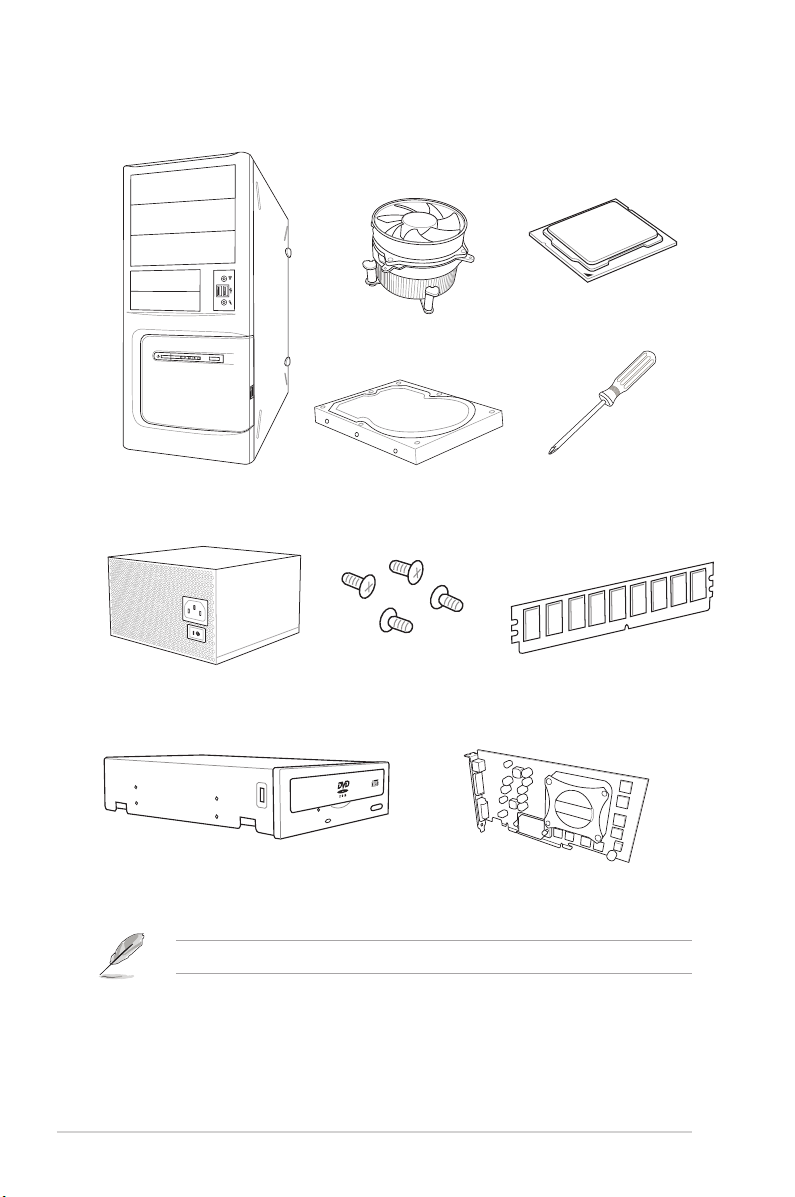
Installation tools and components
Intel® 1151 compatible CPU Fan
Intel® 1151 CPU
PC chassis
Power supply unit
SATA optical disc drive (optional)
SATA hard disk drive
1 bag of screws
Phillips (cross) screwdriver
DIMM
Graphics card
The tools and components listed above are not included in the motherboard package.
xiv
Page 15

Chapter 1: Product Introduction
Product Introduction
1
1.1 Motherboard overview
1.1.1 Before you proceed
Take note of the following precautions before you install motherboard components or change
any motherboard settings.
• Unplug the power cord from the wall socket before touching any component.
• Before handling components, use a grounded wrist strap or touch a safely grounded
object or a metal object, such as the power supply case, to avoid damaging them due
to static electricity.
• Hold components by the edges to avoid touching the ICs on them.
• Whenever you uninstall any component, place it on a grounded antistatic pad or in the
bag that came with the component.
• Before you install or remove any component, ensure that the ATX power supply is
switched off or the power cord is detached from the power supply. Failure to do so
may cause severe damage to the motherboard, peripherals, or components.
Chapter 1
ASUS ROG STRIX Z370-F GAMING
1-1
Page 16
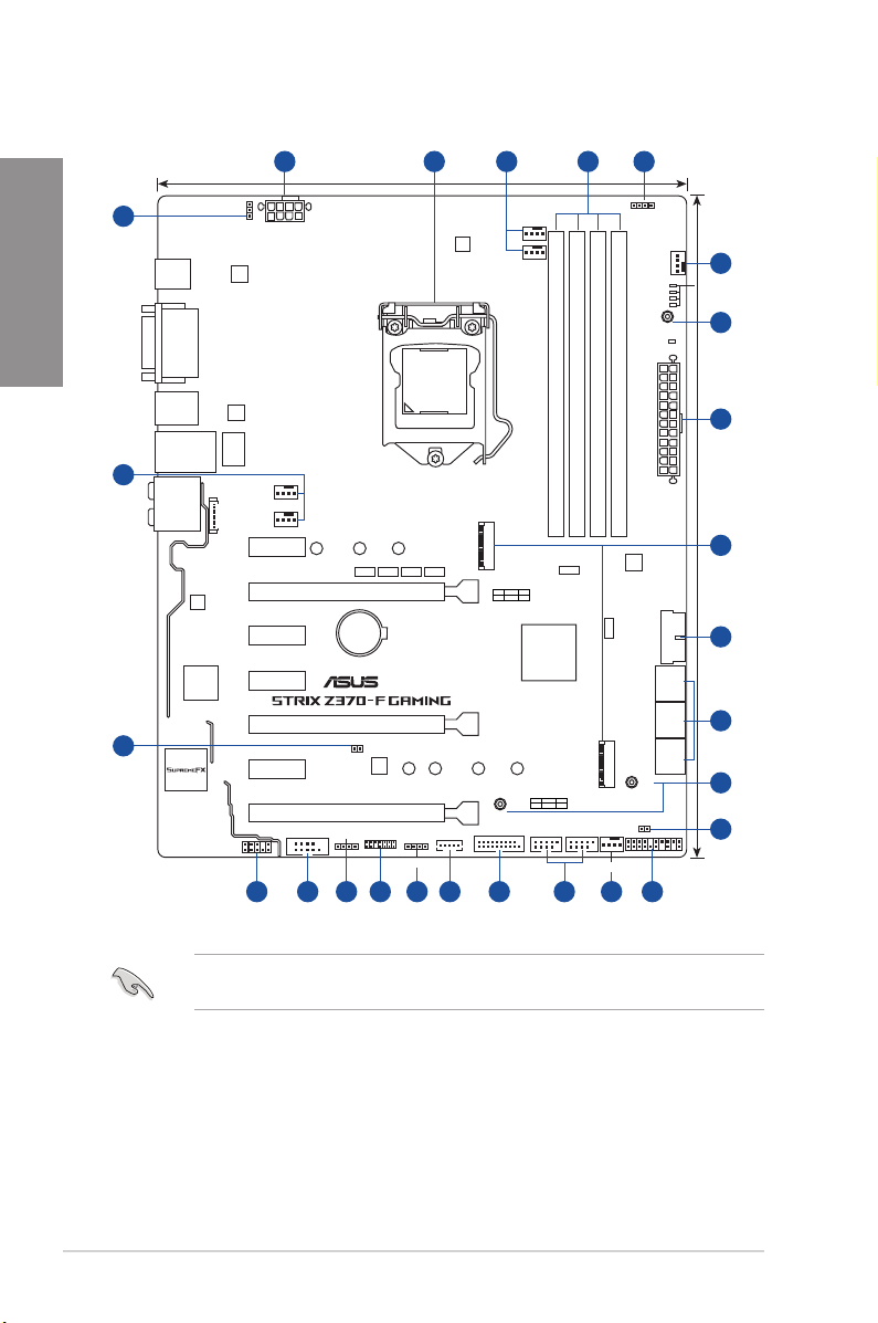
1.1.2 Motherboard layout
Chapter 1
18
3
17
USB31G2_EC1
USB31G2_E2
DP
DVI
HDMI
USB1314
LAN1_U31G1_56
AUDIO
WGI
219V
Super
1 42 53
CPU_OV
EATX12V
ASM
3142
24.4cm(9.6in)
CPU_FAN
DIGI+
EPU
CPU_OPT
RGB_HEADER2
PWR_LED
CHA_FAN1
3D
MOUNT
3
BOOT_DEVICE_LED
VGA_LED
DRAM_LED
CPU_LED
6
LGA1151
ASM
1442K
DDR4 DIMM_B1 (64bit, 288-pin module)
DDR4 DIMM_B2 (64bit, 288-pin module)
DDR4 DIMM_A1 (64bit, 288-pin module)
LANGuard
CHA_FAN2
AIO_PUMP
CON_BACKIO
PCIE_X1_1
2280 2260 2242
ASM1480 ASM1480 ASM1480 ASM1480
PCIE_X16/X8_1
Lithium Cell
PCIE_X1_2
PCIE_X1_3
I/O
CMOS Power
®
M.2_2(SOCKET3)
M.2_2(SOCKET3)
PCIE SATA IRST
X4XV
Intel
Z370
DDR4 DIMM_A2 (64bit, 288-pin module)
ASM
ASM1480
®
3142
ASM1480
PCIE_X8_2
3D
MOUNT
U31G1_34
M.2_1(SOCKET3)
M.2_1(SOCKET3)
PCIE SATA IRST
X4VV
USB910 USB1112
M.2_FAN
PANEL
MOUNT
CLRTC
3D
1131451516
T_SENSOR1
PCIE_X1_4
TPU
2280 2260 2242
PCIE_X4
COM
AAFP
RGB_HEADER1
TPM
EXT_FAN
ADD_HEADER
313 8 12
EATXPWR
SATA6G_1
SATA6G_3
SATA6G_5
U31G1_12
SATA6G_2
SATA6G_4
SATA6G_6
1
30.5cm(12in)
7
8
9
6
10
1-2
Refer to 1.1.8 Internal connectors and 2.2.1 Rear I/O connection for more information
about rear panel connectors and internal connectors.
Chapter 1: Product Introduction
Page 17

Layout contents
Connectors/Jumpers/Buttons and switches/Slots Page
1. ATX power connectors (24-pin EATXPWR; 8-pin EATX12V) 1-16
2. LGA1151 CPU socket 1-4
3. CPU, CPU optional, AIO pump, M.2, extension, and chassis fan
connectors (4-pin CPU_FAN; 4-pin CPU_OPT; 4-pin AIO_PUMP; 4-pin
M.2_FAN; 5-pin EXT_FAN; 4-pin CHA_FAN1-2)
4. DDR4 DIMM slots 1-5
5. RGB headers (4-pin RGB_HEADER1-2) 1-19
6. 3D Mount 1-10
7. M.2 sockets (M.2_1; M.2_2) 1-20
8. USB 3.1 Gen1 connectors (20-1 pin U31G1_12,U31G1_34) 1-13
9. Intel® Serial ATA 6 Gb/s connectors (7-pin SATA6G_12, SATA 6G_34,
SATA 6G_56)
10. Clear RTC RAM jumper (2-pin CLRTC) 1-9
11. System panel connector (20-3 pin PANEL) 1-17
12. USB 2.0 connectors (10-1 pin USB910, USB1112) 1-14
13. Addressable RGB header (4-1 pin ADD_HEADER)
14. TPM connector (14-1 pin TPM) 1-18
15. Serial port connector (10-1 pin COM) 1-14
16. Front panel audio connector (10-1 pin AAFP) 1-13
17. Thermal sensor cable connector (2-pin T_SENSOR) 1-18
18. CPU over voltage jumper (3-pin CPU_OV) 1-10
1-15
Chapter 1
1-12
1-21
ASUS ROG STRIX Z370-F GAMING
1-3
Page 18
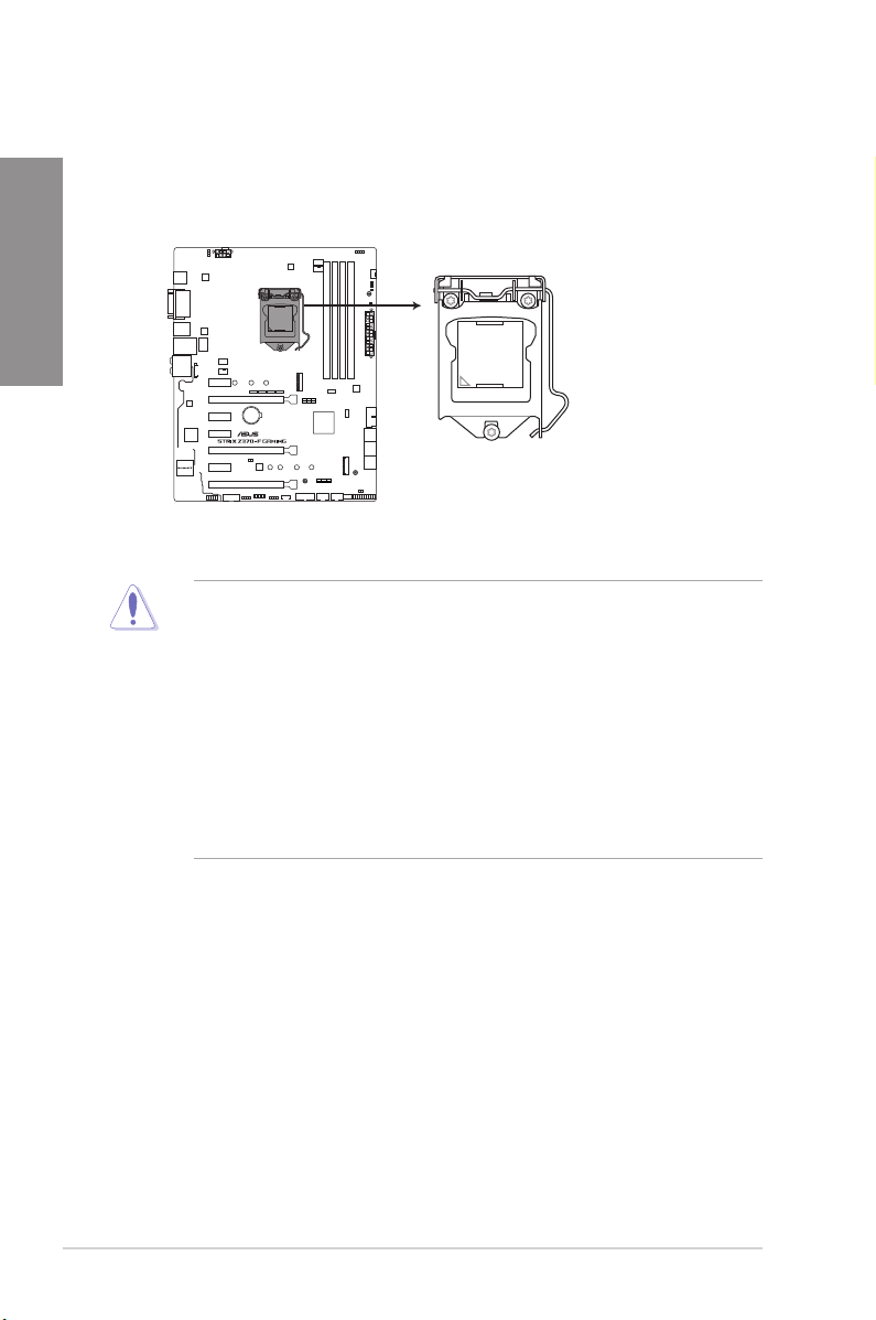
1.1.3 Central Processing Unit (CPU)
ROG STRIX Z370-F GAMING CPU LGA1151
The motherboard comes with a surface mount LGA1151 socket designed for the 8th
Generation Intel® Core™ processors.
Chapter 1
®
• Ensure that all power cables are unplugged before installing the CPU.
• Upon purchase of the motherboard, ensure that the PnP cap is on the socket and
the socket contacts are not bent. Contact your retailer immediately if the PnP cap
is missing, or if you see any damage to the PnP cap/socket contacts/motherboard
components. ASUS will shoulder the cost of repair only if the damage is shipment/
transit-related.
• Keep the cap after installing the motherboard. ASUS will process Return Merchandise
Authorization (RMA) requests only if the motherboard comes with the cap on the
LGA1151 socket.
• The product warranty does not cover damage to the socket contacts resulting from
incorrect CPU installation/removal, or misplacement/loss/incorrect removal of the PnP
cap.
1-4
Chapter 1: Product Introduction
Page 19
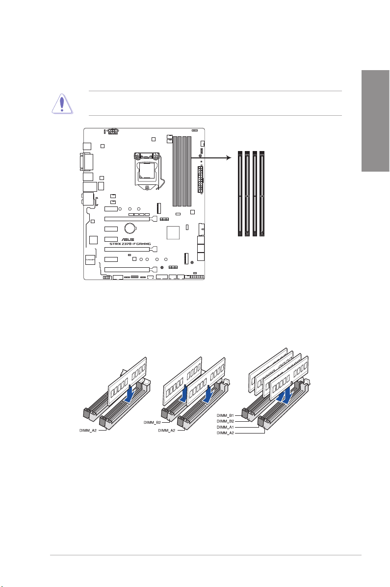
1.1.4 System memory
The motherboard comes with four DDR4 (Double Data Rate 4) Quad Inline Memory Modules
(DIMM) slots.
A DDR4 module is notched differently from a DDR, DDR2, or DDR3 module. DO NOT
install a DDR, DDR2, or DDR3 memory module to the DDR4 slot.
DIMM_B1
DIMM_B2
DIMM_A1
DIMM_A2
®
ROG STRIX Z370-F GAMING
288-pin DDR4 DIMM sockets
Recommended memory congurations
Chapter 1
ASUS ROG STRIX Z370-F GAMING
1-5
Page 20

Memory congurations
You may install 1 GB, 2 GB, 4 GB, 8 GB and 16 GB unbuffered and non-ECC DDR4 DIMMs
into the DIMM sockets.
Chapter 1
• You may install varying memory sizes in Channel A, and Channel B. The system
maps the total size of the lower-sized channel for the dual-channel conguration. Any
excess memory from the higher-sized channel is then mapped for single-channel
operation.
• Due to the memory address limitation on 32-bit Windows® OS, when you install 4GB
or more memory on the motherboard, the actual usable memory for the OS can be
about 3GB or less. For effective use of memory, we recommend that you do any of the
following:
a) Use a maximum of 3GB system memory if you are using a 32-bit Windows® OS.
b) Install a 64-bit Windows® OS when you want to install 4 GB or more on the
motherboard.
c) For more details, refer to the Microsoft® support site at http://support.microsoft.
com/kb/929605/en-us.
• The design of the DIMM fan may vary. Ensure that the DIMM fan ts to the
motherboard
• The default memory operation frequency is dependent on its Serial Presence Detect
(SPD), which is the standard way of accessing information from a memory module.
Under the default state, some memory modules for overclocking may operate at a
lower frequency than the vendor-marked value.
• For system stability, use a more efcient memory cooling system to support a full
memory load (4 DIMMs) or overclocking condition.
• Memory modules with memory frequency higher than 2133MHz and their
corresponding timing or the loaded XMP prole is not the JEDEC memory standard.
The stability and compatibility of the memory modules depend on the CPU’s
capabilities and other installed devices.
• Always install the DIMMS with the same CAS Latency. For an optimum compatibility,
we recommend that you install memory modules of the same version or data code
(D/C) from the same vendor. Check with the vendor to get the correct memory
modules.
• ASUS exclusively provides hyper DIMM support function.
• Hyper DIMM support is subject to the physical characteristics of individual CPUs. Load
the X.M.P. or D.O.C.P. settings in the BIOS for the hyper DIMM support.
• Visit the ASUS website for the latest QVL.
1-6
Chapter 1: Product Introduction
Page 21
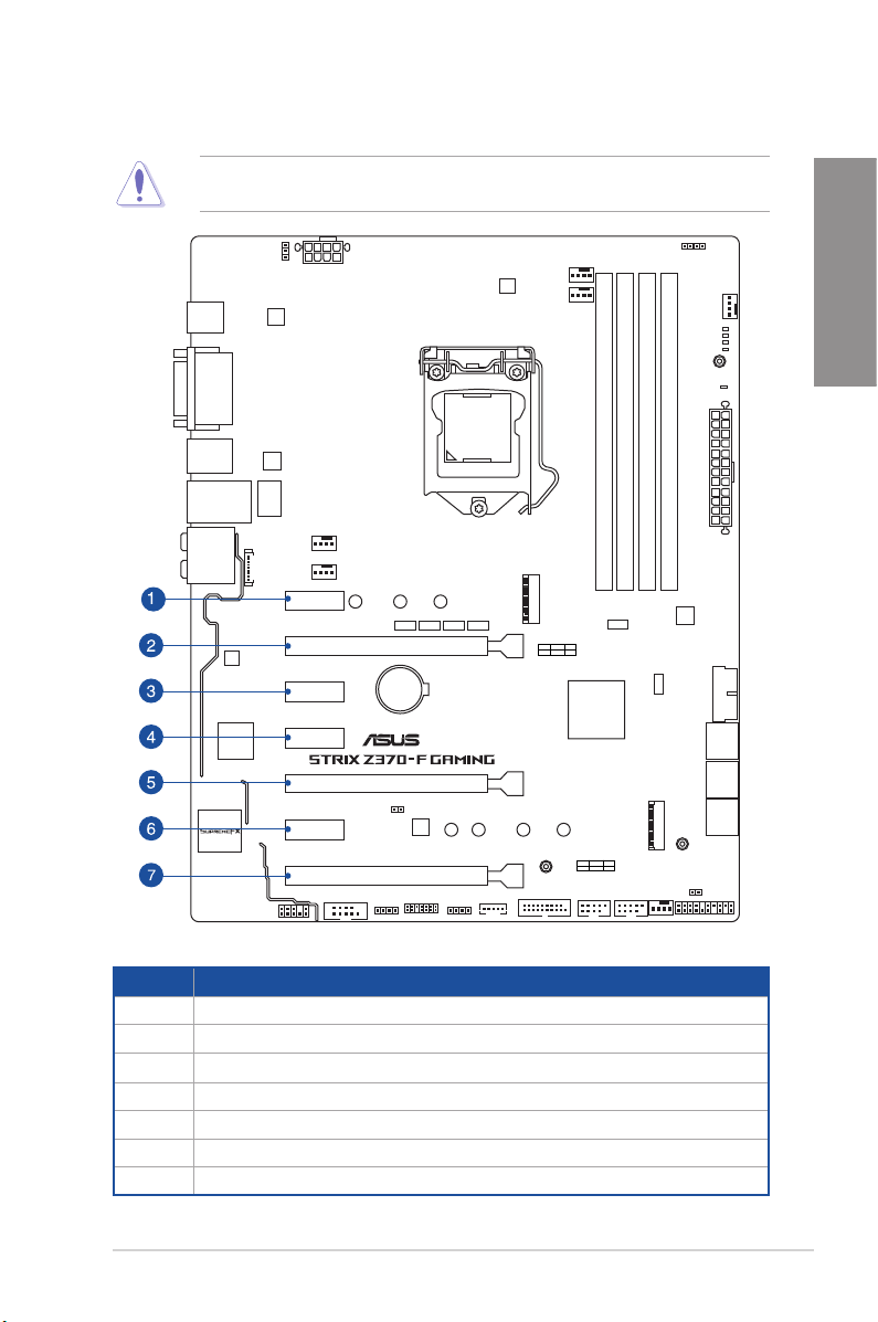
1.1.5 Expansion slots
Unplug the power cord before adding or removing expansion cards. Failure to do so may
cause you physical injury and damage motherboard components.
PCIE_X1_1
PCIE_X16/X8_1
PCIE_X1_2
Chapter 1
PCIE_X1_3
PCIE_X8_2
PCIE_X1_4
PCIE_X4
Slot No. Slot Description
1 PCIE_x1_1 slot
2 PCIE_x16/x8_1 slot
3 PCIE_x1_2 slot
4 PCIE_x1_3 slot
5 PCIE_x8_2 slot
6 PCIE_x1_4 slot
7 PCIE_x4 slot
ASUS ROG STRIX Z370-F GAMING
®
1-7
Page 22
Chapter 1
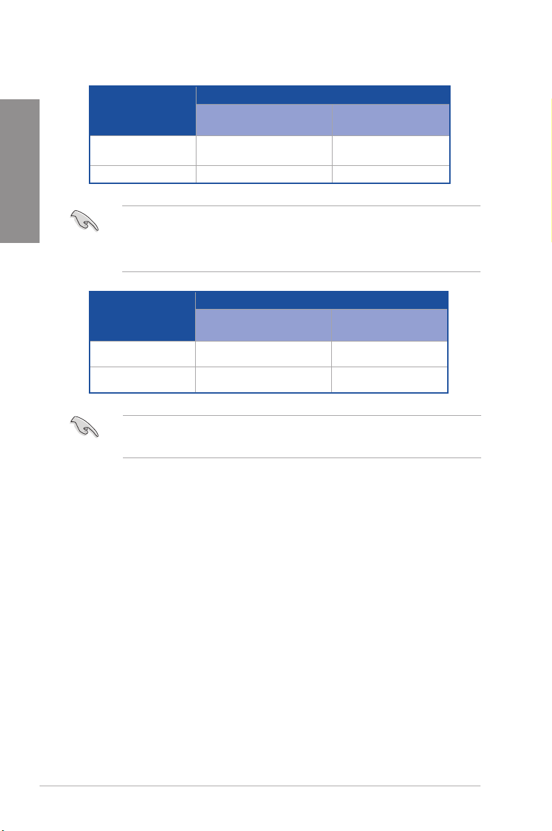
Single VGA/PCIe card
Dual VGA/PCIe cards x8 x8
PCI Express 3.0 operating mode
VGA conguration
• We recommend that you provide sufcient power when running CrossFireX™ or SLI™
mode.
• Connect a chassis fan to the motherboard connector labeled CHA_FAN1-2 when
using multiple graphics cards for better thermal environment.
PCIe_x16/x8_1 PCIe_x8_2
x16 (single VGA
recommended)
N/A
Hyper M.2 X16 card
conguration
2 Intel® SSDs on CPU
support
3 Intel® SSDs on CPU
support
• Hyper M.2 X16 card is purchased separately.
• Enable the Hyper M.2 X16 card under BIOS settings.
PCI Express 3.0 operating mode
PCIe_x16/x8_1 PCIe_x8_2
x8 x4+x4
x8+x4+x4 N/A
1-8
Chapter 1: Product Introduction
Page 23
1.1.6 Jumpers and holes
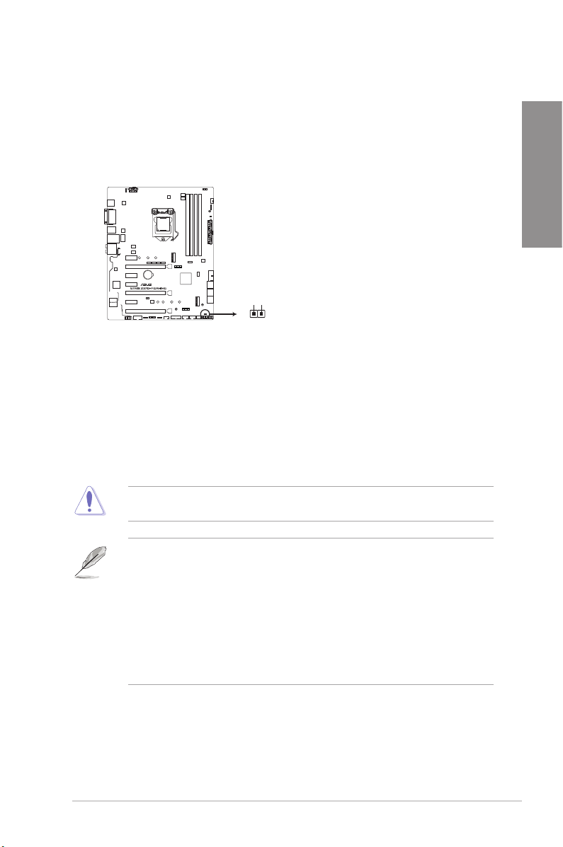
1. Clear RTC RAM jumper (2-pin CLRTC)
This jumper allows you to clear the Real Time Clock (RTC) RAM in CMOS. You can
clear the CMOS memory of date, time, and system setup parameters by erasing the
CMOS RTC RAM data. The onboard button cell battery powers the RAM data in
CMOS, which include system setup information such as system passwords.
Chapter 1
®
ROG STRIX Z370-F GAMING Clear RTC RAM
CLRTC
PIN 1
+3V_BAT
GND
To erase the RTC RAM:
1. Turn OFF the computer and unplug the power cord.
2. Short-circuit pin 1-2 with a metal object or jumper cap for about 5-10 seconds.
3. Plug the power cord and turn ON the computer.
4. Hold down the <Delete> key during the boot process and enter BIOS setup to re-enter
data.
Except when clearing the RTC RAM, never remove the cap on CLRTC jumper default
position. Removing the cap will cause system boot failure!
• If the steps above do not help, remove the onboard battery and move the jumper
again to clear the CMOS RTC RAM data. After the CMOS clearance, reinstall the
battery.
• You do not need to clear the RTC when the system hangs due to overclocking. For
system failure due to overclocking, use the C.P.R. (CPU Parameter Recall) feature.
Shut down and reboot the system so the BIOS can automatically reset parameter
settings to default values.
• Due to the chipset behavior, AC power off is required to enable C.P.R. function. You
must turn off and on the power supply or unplug and plug the power cord before
rebooting the system.
ASUS ROG STRIX Z370-F GAMING
1-9
Page 24
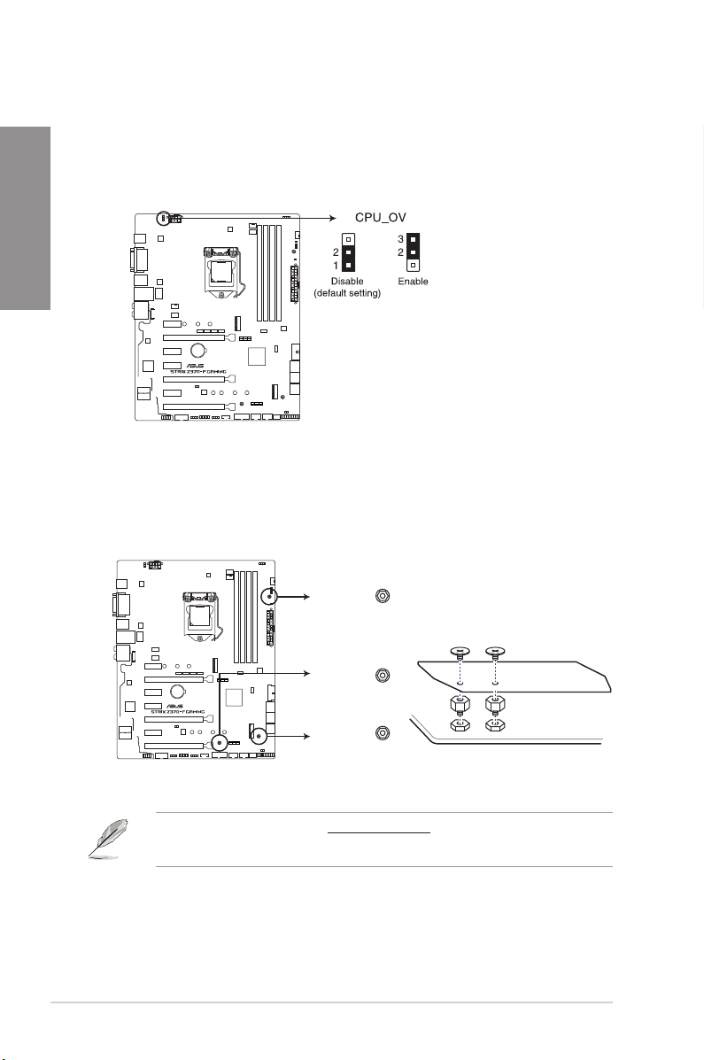
2. CPU over voltage jumper (3-pin CPU_OV)
The CPU over voltage jumper allows you to set a higher CPU voltage for a exible
overclocking system, depending on the type of the installed CPU. To gain more CPU
Chapter 1
voltage setting, insert the jumper to pins 2-3. To go back to its default CPU voltage
setting, insert the jumper to pins 1-2.
3. 3D Mount
Secure 3D printed parts to these 3D Mount holes for a personalized motherboard.
®
ROG STRIX Z370-F GAMING CPU_OV setting
3D Mount
1-10
3D Mount
®
3D Mount
ROG STRIX Z370-F GAMING 3D Printing Mount
• Download 3D source les at http://www.asus.com.
• Use the bundled 3D Mount screws to install the 3D printed parts.
Chapter 1: Product Introduction
Page 25
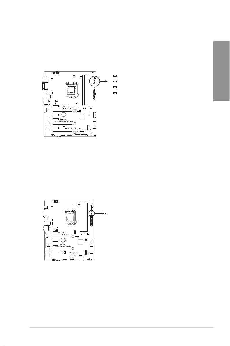
1.1.7 Onboard LEDs
1. POST State LEDs
The POST State LEDs provide the status of these key components during POST
(Power-On Self-Test): CPU, memory modules, VGA card, and hard disk drives. If an
error is found, the critical component’s LED stays lit up until the problem is solved.
BOOT (YELLOW GREEN)
VGA (WHITE)
DRAM (YELLOW)
CPU (RED)
®
ROG STRIX Z370-F GAMING
CPU/DRAM/BOOT_DEVICE/VGA LED
2. Standby Power LED
The motherboard comes with a standby power LED. The LED lights up to indicate that
the system is ON, in sleep mode, or in soft-off mode. This is a reminder that you should
shut down the system and unplug the power cable before removing or plugging in any
motherboard component. The illustration below shows the location of the onboard LED.
Chapter 1
®
ROG STRIX Z370-F GAMING PWR_LED
ASUS ROG STRIX Z370-F GAMING
PWR_LED
1-11
Page 26

1.1.8 Internal connectors
1. Intel® Serial ATA 6 Gb/s connectors (7-pin SATA6G_12, SATA 6G_34, SATA
Chapter 1
6G_56)
These connectors connect to Serial ATA 6 Gb/s hard disk drives via Serial ATA 6 Gb/s
signal cables.
If you installed Serial ATA hard disk drives, you can create a RAID 0, 1, 5, and 10
conguration with the Intel® Rapid Storage Technology through the onboard Intel®
Z370 chipset.
SATA6G_1
GND
RSATA_TXP1
RSATA_TXN1
GND
RSATA_RXN1
RSATA_RXP1
GND
SATA6G_3
GND
RSATA_TXP3
RSATA_TXN3
GND
RSATA_RXN3
RSATA_RXP3
GND
®
SATA6G_5
RSATA_TXP5
RSATA_TXN5
RSATA_RXN5
RSATA_RXP5
GND
GND
GND
SATA6G_2
RSATA_TXP2
RSATA_TXN2
RSATA_RXN2
RSATA_RXP2
SATA6G_4
RSATA_TXP4
RSATA_TXN4
RSATA_RXN4
RSATA_RXP4
SATA6G_6
RSATA_TXP6
RSATA_TXN6
RSATA_RXN6
RSATA_RXP6
GND
GND
GND
GND
GND
GND
GND
GND
GND
ROG STRIX Z370-F GAMING Intel® SATA 6 Gb/s connectors
• These connectors are set to [AHCI] by default. If you intend to create a Serial ATA
RAID set using these connectors, set the SATA Mode item in the BIOS to [Intel RST
Premium With Intel Optane System Acceleration (RAID)].
• Before creating a RAID set, refer to the manual bundled in the motherboard support
DVD.
1-12
Chapter 1: Product Introduction
Page 27
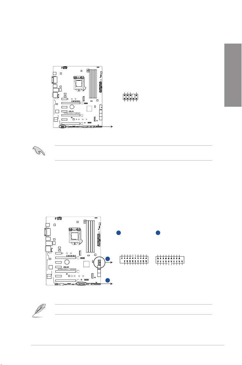
2. Front panel audio connector (10-1 pin AAFP)
This connector is for a chassis-mounted front panel audio I/O module that supports HD
Audio. Connect one end of the front panel audio I/O module cable to this connector.
AGNDNCSENSE1_RETUR
SENSE2_RETUR
AAFP
Chapter 1
®
PORT1 L
PORT1 R
PORT2 R
SENSE_SEND
HD-audio-compliant
pin definition
PORT2 L
ROG STRIX Z370-F GAMING Analog front panel connector
We recommend that you connect a high-denition front panel audio module to this
connector to avail of the motherboard’s high-denition audio capability.
4. USB 3.1 Gen1 connectors (20-1 pin U31G1_12, U31G1_34)
These connectors allow you to connect a USB 3.1 Gen1 module for additional USB 3.1
Gen1 front or rear panel ports. With an installed USB 3.1 Gen1 module, you can enjoy
all the benets of USB 3.1 Gen1 including faster data transfer speeds of up to 5 Gb/s,
faster charging time for USB-chargeable devices, optimized power efciency, and
backward compatibility with USB 2.0.
A
U31G1_12
Vbus
IntA_P1_SSRX-
IntA_P1_SSRX+
GND
IntA_P1_SSTX-
IntA_P1_SSTX+
Vbus
IntA_P2_SSRX-
IntA_P2_SSRX+
GND
GND
IntA_P2_SSTX-
IntA_P2_SSTX+
PIN 1
A
®
B
IntA_P1_D-
IntA_P1_D+
GND
GND
IntA_P2_D-
IntA_P2_D+
B
U31G1_34
IntA_P2_D+
IntA_P2_D-
GND
IntA_P2_SSTX+
GND
GND
IntA_P1_D-
IntA_P1_D+
IntA_P2_SSTX-
GND
IntA_P2_SSRX+
IntA_P2_SSRX-
Vbus
GND
IntA_P1_SSTX-
IntA_P1_SSRX-
IntA_P1_SSTX+
IntA_P1_SSRX+
PIN 1
Vbus
ROG STRIX Z370-F GAMING USB 3.1 Gen1 connectors
The USB 3.1 Gen1 module is purchased separately.
ASUS ROG STRIX Z370-F GAMING
1-13
Page 28
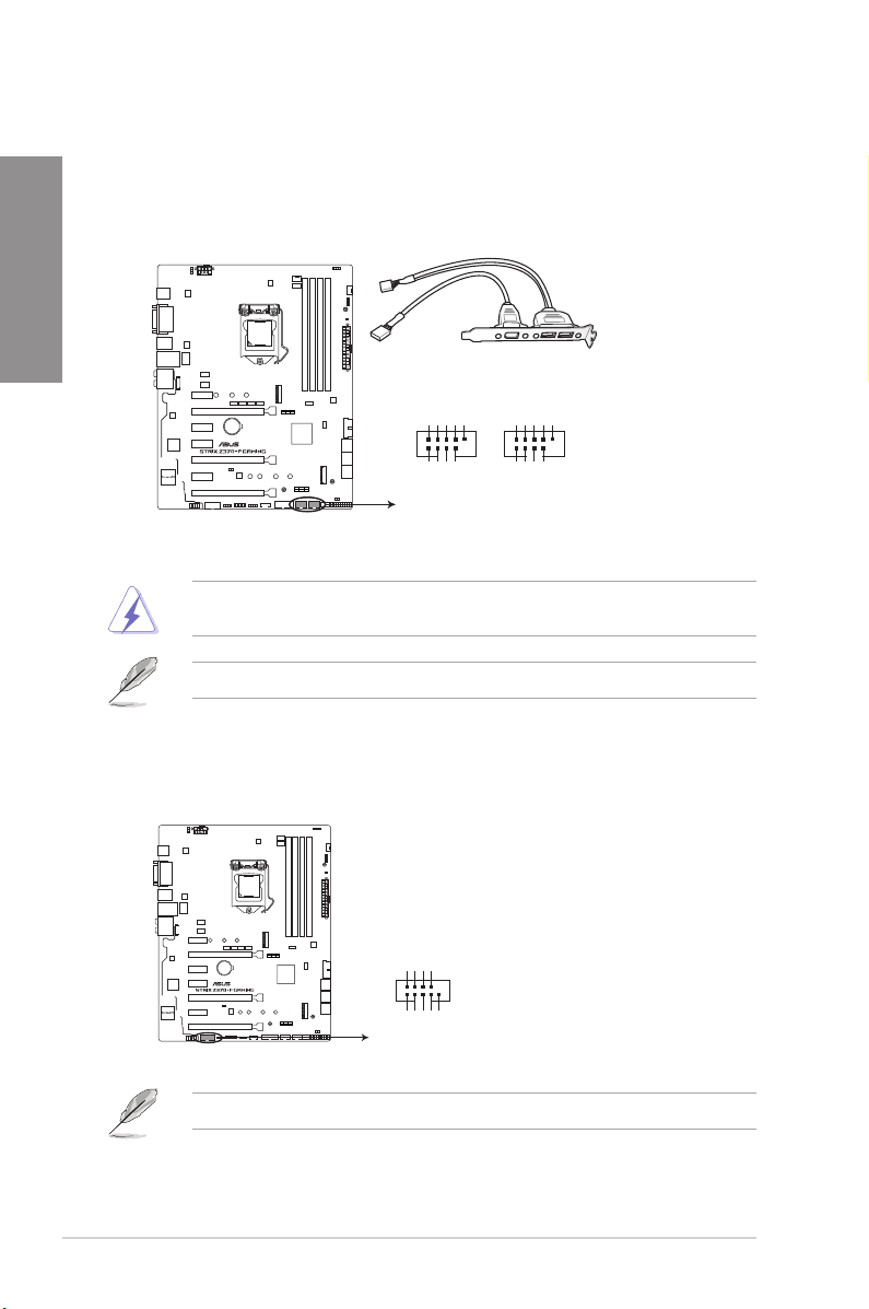
5. USB 2.0 connectors (10-1 pin USB910, USB1112)
These connectors are for USB 2.0 ports. Connect the USB module cable to these
connectors, then install the module to a slot opening at the back of the system chassis.
Chapter 1
This USB connector complies with USB 2.0 specication that supports up to 480 Mb/s
connection speed.
USB910
USB+5V
®
USB_P10-
PIN 1
USB+5V
USB_P9-
USB_P10+
GND
NC
GND
USB_P9+
USB1112
PIN 1
USB+5V
USB_P12-
USB+5V
USB_P11-
USB_P12+
GND
NC
GND
USB_P11+
ROG STRIX Z370-F GAMING USB2.0 connector
DO NOT connect a 1394 cable to the USB connectors. Doing so will damage the
motherboard!
The USB 2.0 module is purchased separately.
6. Serial port connector (10-1 pin COM)
This connector is for a serial (COM) port. Connect the serial port module cable to this
connector, then install the module to a slot opening at the back of the system chassis.
RXD1
DTR1
DSR1
®
COM
ROG STRIX Z370-F GAMING Serial port connector
CTS1
PIN 1
PI1#
GND
TXD1
DCD1
RTS1#
1-14
The COM module is purchased separately.
Chapter 1: Product Introduction
Page 29
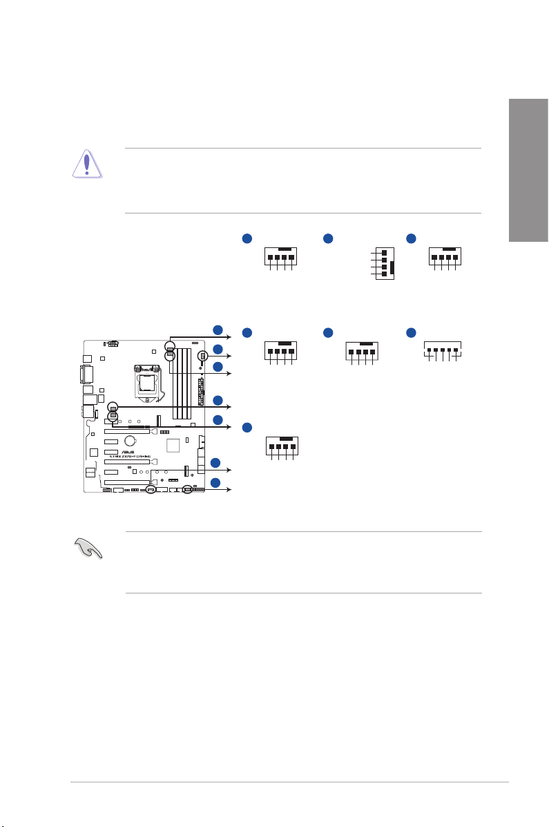
7. CPU, CPU optional, AIO pump, M.2, extension, and chassis fan connectors (4-pin
CPU_FAN; 4-pin CPU_OPT; 4-pin AIO_PUMP; 4-pin M.2_FAN; 5-pin EXT_FAN;
4-pin CHA_FAN1-2)
Connect the fan cables to the fan connectors on the motherboard, ensuring that the
black wire of each cable matches the ground pin of the connector.
• DO NOT forget to connect the fan cables to the fan connectors. Insufcient air ow
inside the system may damage the motherboard components. These are not jumpers!
Do not place jumper caps on the fan connectors!
• Ensure that the CPU fan cable is securely installed to the CPU fan connector.
Chapter 1
A
CPU_FAN
CPU FAN IN
CPU FAN PWR
A
B
C
D
E
®
F
G
CPU FAN PWM
D
CHA_FAN2
CHA FAN PWM
G
M.2_FAN
M.2 PWM
CHA FAN IN
CHA FAN PWR
M.2 IN
M.2 PWR
ROG STRIX Z370-F GAMING Fan connectors
• The CPU_FAN connector supports the CPU fan of maximum 1A (12 W) fan power.
• The EXT_FAN connector supports 2 of 5 thermal sensor sources.
• Connect the fan of your water cooling kit to the AIO_PUMP connector.
GND
GND
GND
B
CHA_FAN1
CHA FAN PWM
CHA FAN IN
CHA FAN PWR
GND
E
AIO_PUMP
AIO PUMP PWM
C
CPU_OPT
GND
CPU FAN IN
CPU FAN PWR
CPU FAN PWM
F
EXT_FAN
GND
AIO PUMP IN
AIO PUMP PWR
GND
Control2
Control1
Sense2
Sense1
ASUS ROG STRIX Z370-F GAMING
1-15
Page 30
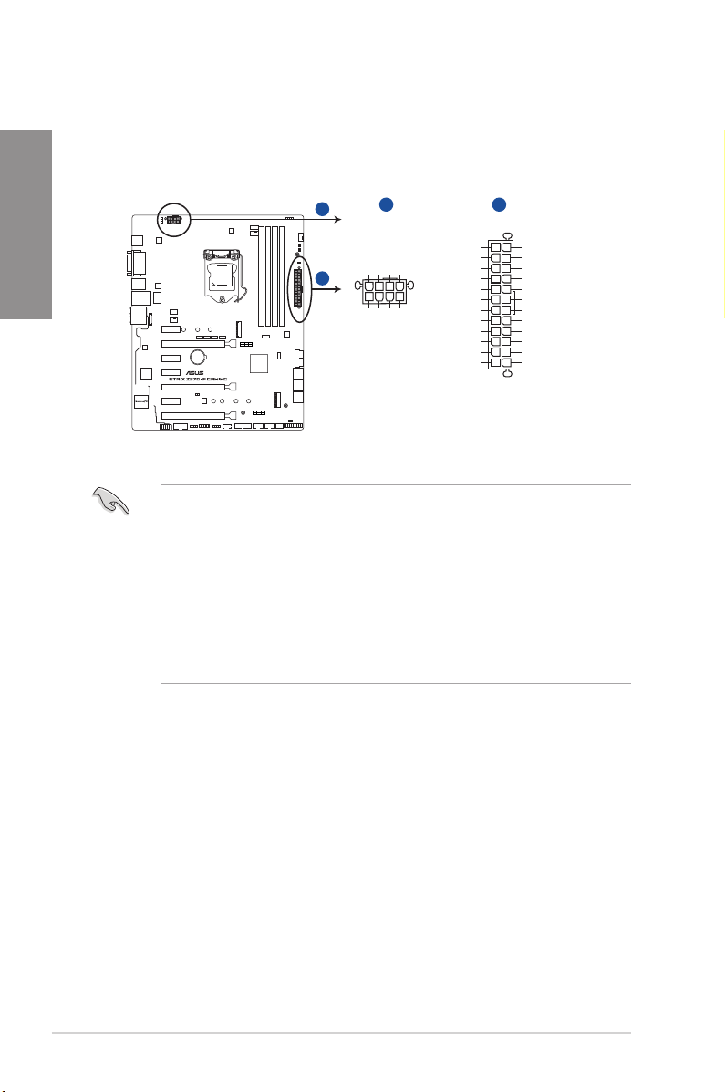
8. ATX power connectors (24-pin EATXPWR; 8-pin EATX12V)
These connectors are for ATX power supply plugs. The power supply plugs are
designed to t these connectors in only one orientation. Find the proper orientation and
Chapter 1
push down rmly until the connectors completely t.
A
B
®
A B
EATX12V
+12 Volts
+12 Volts
+12V DC
+12V DC
+12V DC
+12V DC
GND
GND
GND
PIN 1
GND
+5V Standby
Power OK
EATXPWR
+3 Volts
GND
+5 Volts
GND
+5 Volts
GND
+3 Volts
+3 Volts
GND
+5 Volts
+5 Volts
+5 Volts
-5 Volts
GND
GND
GND
PSON#
GND
-12 Volts
+3 Volts
PIN 1
ROG STRIX Z370-F GAMING ATX power connectors
• For a fully congured system, we recommend that you use a power supply unit
(PSU) that complies with ATX 12 V Specication 2.0 (or later version) and provides a
minimum power of 350 W.
• DO NOT forget to connect the 8-pin EATX12V power plug. Otherwise, the system will
not boot.
• We recommend that you use a PSU with a higher power output when conguring a
system with more power-consuming devices. The system may become unstable or
may not boot up if the power is inadequate.
• If you want to use two or more high-end PCI Express x16 cards, use a PSU with
1000W power or above to ensure the system stability.
1-16
Chapter 1: Product Introduction
Page 31

9. System panel connector (20-3 pin PANEL)
This connector supports several chassis-mounted functions.
PLED
PANEL
®
PIN 1
HDD_LED
PWRSW
PLED+
PLED-
PWRBTN#
GND
Ground
RSTCON#
HDD_LED-
HDD_LED+
RESET
SPEAKER
+5V
NC
PLED+
PLED
Ground
Ground
PLED-
CHASSIS
Speaker
Intruder#
GND
ROG STRIX Z370-F GAMING System panel connector
• System power LED (2-pin or 3-1 pin PLED)
The 2-pin or 3-1 pin connector is for the system power LED. Connect the chassis
power LED cable to this connector. The system power LED lights up when you turn on
the system power, and blinks when the system is in sleep mode.
• Hard disk drive activity LED (2-pin HDD_LED)
This 2-pin connector is for the HDD Activity LED. Connect the HDD Activity LED cable
to this connector. The HDD LED lights up or ashes when data is read from or written
to the HDD.
• System warning speaker (4-pin SPEAKER)
This 4-pin connector is for the chassis-mounted system warning speaker. The speaker
allows you to hear system beeps and warnings.
• ATX power button/soft-off button (2-pin PWRSW)
This connector is for the system power button. Pressing the power button turns the
system on or puts the system in sleep or soft-off mode depending on the operating
system settings. Pressing the power switch for more than four seconds while the
system is ON turns the system OFF.
• Reset button (2-pin RESET)
This 2-pin connector is for the chassis-mounted reset button for system reboot without
turning off the system power.
• Chassis intrusion connector (2-pin CHASSIS)
This connector is for a chassis-mounted intrusion detection sensor or switch. Connect
one end of the chassis intrusion sensor or switch cable to this connector. The chassis
intrusion sensor or switch sends a high-level signal to this connector when a chassis
component is removed or replaced. The signal is then generated as a chassis intrusion
event.
Chapter 1
ASUS ROG STRIX Z370-F GAMING
1-17
Page 32

10. TPM connector (14-1 pin TPM)
This connector supports a Trusted Platform Module (TPM) system, which securely
stores keys, digital certicates, passwords and data. A TPM system also helps
Chapter 1
enhance network security, protect digital identities, and ensures platform integrity.
11. Thermal sensor connector (2-pin T_SENSOR)
This connector is for the thermistor cable that monitors the temperature of the devices
and the critical components inside the motherboard. Connect the thermistor cable
and place the sensor on the device or the motherboard’s component to detect its
temperature.
TPM
F_CLKRUN
F_SERIRQ
F_FRAME#
F_LAD3
F_LAD2
F_LAD1
F_LAD0
PIN 1
+3V
+3V
®
GND
+3VSB
C_PCICLK_TPM
S_PCIRST#_TBD
ROG STRIX Z370-F GAMING TPM connector
The TPM module is purchased separately.
1-18
®
T_SENSOR
GND
PIN 1
SENSOR IN
ROG STRIX Z370-F GAMING T_SENSOR connector
Chapter 1: Product Introduction
Page 33

12. RGB headers (4-pin RGB_HEADER1-2)
These connectors are for RGB LED strips.
A
RGB_HEADER2
A
PIN 1
+12V G R B
B
RGB_HEADER1
PIN 1
+12V G R B
®
B
ROG STRIX Z370-F GAMING RGB_HEADER connectors
The RGB header supports 5050 RGB multi-color LED strips (12V/G/R/B), with a maximum
power rating of 2A (12V), and no longer than 2 m.
Before you install or remove any component, ensure that the ATX power supply is switched
off or the power cord is detached from the power supply. Failure to do so may cause severe
damage to the motherboard, peripherals, or components.
Chapter 1
• Actual lighting and color will vary with LED strip.
• If your LED strip does not light up, check if the RGB LED extension cable and the
RGB LED strip is connected in the correct orientation, and the 12V connector is
aligned with the 12V header on the motherboard.
• The LED strip will only light up when the system is operating.
• The LED strips are purchased separately.
ASUS ROG STRIX Z370-F GAMING
1-19
Page 34

13. M.2 sockets (M.2_1; M.2_2)
These sockets allow you to install M.2 SSD modules.
Chapter 1
A
M.2_2(SOCKET3)
2280 2260 2242
B
A
M.2_1(SOCKET3)
®
B
2280 2260 2242
ROG STRIX Z370-F GAMING M.2 sockets
• M.2_1 socket supports PCIe 3.0 x4 and SATA mode M Key design and type 2242 /
2260 / 2280 PCIe and SATA storage devices.
• M.2_2 socket supports PCIe 3.0 x4 M Key design and type 2242 / 2260 / 2280 PCIe
storage devices.
• These sockets support IRST (Intel® Rapid Storage Technology).
The M.2 SSD module is purchased separately.
1-20
Chapter 1: Product Introduction
Page 35

14. Addressable RGB header (4-1 pin ADD_HEADER)
This connector is for individually addressable RGB WS2812B LED strips with
embedded WS2811LED driver ICs.
®
ROG STRIX Z370-F GAMING EXTREME ADD header
The addressable RGB header supports WS2812B addressable RGB LED strips (5V/Data/
Ground), with a maximum power rating of 3A (5V) and a maximum of 60 LEDs.
Before you install or remove any component, ensure that the ATX power supply is switched
off or the power cord is detached from the power supply. Failure to do so may cause severe
damage to the motherboard, peripherals, or components.
• Actual lighting and color will vary with LED strip.
• If your LED strip does not light up, check if the addressable RGB LED strip is
connected in the correct orientation, and the 5V connector is aligned with the 5V
header on the motherboard.
• The addressable RGB LED strip will only light up under the operating system.
• The addressable RGB LED strip is purchased separately.
Chapter 1
ASUS ROG STRIX Z370-F GAMING
1-21
Page 36

Chapter 1
1-22
Chapter 1: Product Introduction
Page 37

Chapter 2: Basic Installation
Basic Installation
2.1 Building your PC system
The diagrams in this section are for reference only. The motherboard layout may vary with
models, but the installation steps are the same for all models.
2.1.1 Motherboard installation
1. Install the ASUS Q-Shield to the chassis rear I/O panel.
2
Chapter 2
2. Place the motherboard into the chassis, ensuring that its rear I/O ports are aligned to
the chassis’ rear I/O panel.
ASUS ROG STRIX Z370-F GAMING
2-1
Page 38

3. Place nine (9) screws into the holes indicated by circles to secure the motherboard to
the chassis.
Chapter 2
2-2
®
DO NOT overtighten the screws! Doing so can damage the motherboard.
Chapter 2: Basic Installation
Page 39

2.1.2 CPU installation
Ensure that you install the correct CPU designed for LGA1151 socket only. DO NOT install
a CPU designed for LGA1155 and LGA1156 sockets on the LGA1151 socket.
Top of CPU
Chapter 2
Bottom of CPU
ASUS ROG STRIX Z370-F GAMING
Bottom of CPU
2-3
Page 40

Chapter 2
Top of CPU
• The CPU Installation Tool is only compatible on ASUS motherboards with a Intel®
LGA1151 socket.
• Ensure that the CPU is rmly clicked into place before installing it onto the CPU socket
on the motherboard.
• Use the CPU Installation Tool for installing the CPU only. DO NOT damage or bend
the CPU Installation Tool.
• Always rmly hold both sides of the CPU Installation Tool when installing, removing, or
picking up the CPU Installation Tool.
• Ensure to use a soft stable surface when installing the CPU to the CPU Installation
Tool to prevent CPU damage.
• ASUS will not cover damages resulting from incorrect CPU installation/removal,
incorrect CPU orientation/placement, or other damages resulting from negligence by
the user.
2-4
Chapter 2: Basic Installation
Page 41

2.1.3 CPU heatsink and fan assembly installation
Apply the Thermal Interface Material to the
CPU heatsink and CPU before you install
the heatsink and fan, if necessary.
To install the CPU heatsink and fan assembly
Chapter 2
ASUS ROG STRIX Z370-F GAMING
2-5
Page 42

To uninstall the CPU heatsink and fan assembly
Chapter 2
2-6
Chapter 2: Basic Installation
Page 43

2.1.4 DIMM installation
Chapter 2
To remove a DIMM
ASUS ROG STRIX Z370-F GAMING
2-7
Page 44

2.1.5 ATX power connection
Chapter 2
Ensure to connect the 8-pin power plug.
2-8
Chapter 2: Basic Installation
Page 45

2.1.6 SATA device connection
OR
Chapter 2
ASUS ROG STRIX Z370-F GAMING
2-9
Page 46

2.1.7 Front I/O connector
To install front panel connector
Chapter 2
To install USB 2.0 connector
To install USB 3.1 Gen1 connector
USB 3.1 Gen1
To install front panel audio connector
AAFP
USB 2.0
2-10
Chapter 2: Basic Installation
Page 47

2.1.8 Expansion card installation
To install PCIe x16 cards
To install PCIe x1 cards
Chapter 2
ASUS ROG STRIX Z370-F GAMING
2-11
Page 48

To install HYPER M.2 x4 card
Chapter 2
2-12
The SSD card is purchased separately.
Chapter 2: Basic Installation
Page 49

2.1.9 M.2 installation
Chapter 2
• Please remove the plastic lm from the thermal pad before use.
• Use the bundled M.2 screws to secure the M.2.
ASUS ROG STRIX Z370-F GAMING
2-13
Page 50

Chapter 2
Supported M.2 type varies per motherboard.
2-14
Use the bundled M.2 screws to secure the M.2.
Chapter 2: Basic Installation
Page 51

2.1.10 Fan holder installation
To install the Fan holder and fan
1
2
3
®
When using high performance settings whilst overclocking, ensure to install the fan holder
for additional fan(s).
• You may install 40mm x 40mm fans or 50mm x 50mm fans.
• Fans are purchased separately.
4
5
Chapter 2
ASUS ROG STRIX Z370-F GAMING
2-15
Page 52

2.2 Motherboard rear and audio connections
8
5 109
76
2.2.1 Rear I/O connection
Chapter 2
Rear panel connectors
1.
2.
3.
4.
5. USB 3.1 Gen2 Type-C port EC1 10. Audio I/O ports**
* and ** : Refer to the tables on the next page for LAN port LEDs and audio port denitions.
1
USB 3.1 Gen2 Type-A port E2 6. DisplayPort
DVI-D port 7. HDMI 1.4b port
USB 2.0 ports 8. USB 3.1 Gen1 ports
Intel® LAN port (LAN1)* 9. Optical S/PDIF Out port
• The plugged USB 3.1 Gen1 device may run on xHCI mode or EHCI mode, depending
on the operating system’s setting.
• USB 3.1 Gen1 devices can only be used as data storage only.
• We strongly recommend that you connect USB 3.1 Gen1 devices to USB 3.1 Gen1
ports for faster and better performance for your USB 3.1 Gen1 devices.
2
3
4
2-16
Chapter 2: Basic Installation
Page 53

** LAN ports LED indications
Activity Link LED Speed LED
Status Description Status Description
Off
Orange
Orange (Blinking)
Orange (Blinking
then steady)
You can disable the LAN controllers in BIOS. Due to hardware design, the LAN1 port’s
LEDs may continue to blink even when disabled.
No link Off 10 Mbps connection
Linked Orange 100 Mbps connection
Data activity Green 1 Gbps connection
Ready to wake up
from S5 mode
ACT/LINK
LED
LAN port
SPEED
LED
*** Audio 2, 4, 6, or 8-channel conguration
Port
Light Blue Line In Line In Line In Side speaker
Lime Line Out Front Speaker Out Front Speaker Out Front Speaker Out
Pink Mic In Mic In Mic In Mic In
Orange – – Center/Subwoofer Center/Subwoofer
Black – Rear Speaker Out Rear Speaker Out Rear Speaker Out
Headset
2-channel
4-channel 6-channel 8-channel
Chapter 2
ASUS ROG STRIX Z370-F GAMING
2-17
Page 54

2.2.2 Audio I/O connections
Audio I/O ports
Connect to Headphone and Mic
Chapter 2
Connect to Stereo Speakers
Connect to 2 channel Speakers
2-18
Chapter 2: Basic Installation
Page 55

Connect to 4 channel Speakers
Connect to 6 channel Speakers
Chapter 2
ASUS ROG STRIX Z370-F GAMING
2-19
Page 56

Connect to 8 channel Speakers
Chapter 2
2.3 Starting up for the rst time
1. After making all the connections, replace the system case cover.
2. Ensure that all switches are off.
3. Connect the power cord to the power connector at the back of the system chassis.
4. Connect the power cord to a power outlet that is equipped with a surge protector.
5. Turn on the devices in the following order:
a. Monitor
b. External SCSI devices (starting with the last device on the chain)
c. System power
6. After applying power, the system power LED on the system front panel case lights up.
For systems with ATX power supplies, the system LED lights up when you press the
ATX power button. If your monitor complies with the “green” standards or if it has a
“power standby” feature, the monitor LED may light up or change from orange to green
after the system LED turns on.
The system then runs the power-on self tests (POST). While the tests are running, the
BIOS beeps (refer to the BIOS beep codes table) or additional messages appear on
the screen. If you do not see anything within 30 seconds from the time you turned on
the power, the system may have failed a power-on test. Check the jumper settings and
connections or call your retailer for assistance.
2-20
Chapter 2: Basic Installation
Page 57

BIOS Beep Description
One short beep VGA detected
Quick boot set to disabled
No keyboard detected
One continuous beep followed by two
short beeps then a pause (repeated)
One continuous beep followed by three
short beeps
One continuous beep followed by four
short beeps
7. At power on, hold down the <Delete> key to enter the BIOS Setup. Follow the
instructions in Chapter 3.
No memory detected
No VGA detected
Hardware component failure
2.4 Turning off the computer
While the system is ON, press the power button for less than four seconds to put the system
on sleep mode or soft-off mode, depending on the BIOS setting. Press the power switch
for more than four seconds to let the system enter the soft-off mode regardless of the BIOS
setting.
Chapter 2
ASUS ROG STRIX Z370-F GAMING
2-21
Page 58

Chapter 2
2-22
Chapter 2: Basic Installation
Page 59

Chapter 3: BIOS Setup
BIOS Setup
3
3.1 Knowing BIOS
The new ASUS UEFI BIOS is a Unied Extensible Interface that complies with UEFI
architecture, offering a user-friendly interface that goes beyond the traditional keyboard-
only BIOS controls to enable a more exible and convenient mouse input. You can easily
navigate the new UEFI BIOS with the same smoothness as your operating system. The
term “BIOS” in this user manual refers to “UEFI BIOS” unless otherwise specied.
BIOS (Basic Input and Output System) stores system hardware settings such as storage
device conguration, overclocking settings, advanced power management, and boot
device conguration that are needed for system startup in the motherboard CMOS. In
normal circumstances, the default BIOS settings apply to most conditions to ensure
optimal performance. DO NOT change the default BIOS settings except in the following
circumstances:
• An error message appears on the screen during the system bootup and requests you to
run the BIOS Setup.
• You have installed a new system component that requires further BIOS settings or
update.
Inappropriate BIOS settings may result to instability or boot failure. We strongly
recommend that you change the BIOS settings only with the help of a trained service
personnel.
When downloading or updating the BIOS le, rename it as Z370FGAM.CAP for this
motherboard.
ASUS ROG STRIX Z370-F GAMING
Chapter 3
3-1
Page 60

3.2 BIOS setup program
Use the BIOS Setup to update the BIOS or congure its parameters. The BIOS screen
include navigation keys and brief onscreen help to guide you in using the BIOS Setup
program.
Entering BIOS at startup
To enter BIOS Setup at startup, press <Delete> or <F2> during the Power-On Self Test
(POST). If you do not press <Delete> or <F2>, POST continues with its routines.
Entering BIOS Setup after POST
To enter BIOS Setup after POST:
• Press <Ctrl>+<Alt>+<Delete> simultaneously.
• Press the reset button on the system chassis.
• Press the power button to turn the system off then back on. Do this option only if you
failed to enter BIOS Setup using the rst two options.
After doing either of the three options, press <Delete> key to enter BIOS.
Chapter 3
• The BIOS setup screens shown in this section are for reference purposes only, and
may not exactly match what you see on your screen.
• Ensure that a USB mouse is connected to your motherboard if you want to use the
mouse to control the BIOS setup program.
• If the system becomes unstable after changing any BIOS setting, load the default
settings to ensure system compatibility and stability. Select the Load Optimized
Defaults item under the Exit menu or press hotkey <F5>. See section 3.10 Exit Menu
for details.
• If the system fails to boot after changing any BIOS setting, try to clear the CMOS and
reset the motherboard to the default value. See section 1.1.6 Jumpers and holes for
information on how to erase the RTC RAM via the Clear CMOS jumper.
• The BIOS setup program does not support the Bluetooth devices.
Please visit ASUS website for the detailed BIOS content manual.
BIOS menu screen
The BIOS Setup program can be used under two modes: EZ Mode and Advanced Mode.
You can change modes from Setup Mode in Boot menu or by pressing the <F7> hotkey.
3-2
Chapter 3: BIOS Setup
Page 61

3.2.1 EZ Mode
By default, the EZ Mode screen appears when you enter the BIOS setup program. The EZ
Mode provides you an overview of the basic system information, and allows you to select
the display language, system performance, mode and boot device priority. To access the
Advanced Mode, select Advanced Mode or press the <F7> hotkey for the advanced BIOS
settings.
The default screen for entering the BIOS setup program can be changed. Refer to the
Setup Mode item in section Boot menu for details.
Displays the system properties of the selected mode.
Displays the CPU/motherboard temperature,
CPU voltage output, CPU/chassis/power fan
speed, and SATA information
Selects the display language
of the BIOS setup program
Click < or > to switch EZ System Tuning modes
Creates storage RAID and
congures system overclocking
Enables or disables the SATA RAID mode
for Intel Rapid Storage Technology
Displays the CPU Fan’s speed. Click
the button to manually tune the fans
Loads optimized
default settings
The boot device options vary depending on the devices you installed to the system.
ASUS ROG STRIX Z370-F GAMING
Saves the changes
and resets the system
Click to go to Advanced mode
Click to display boot devices
Selects the boot device priority
Chapter 3
Search on the FAQ
3-3
Page 62

3.2.2 Advanced Mode
The Advanced Mode provides advanced options for experienced end-users to congure
the BIOS settings. The gure below shows an example of the Advanced Mode. Refer to the
following sections for the detailed congurations.
To switch from EZ Mode to Advanced Mode, click Advanced Mode(F7) or press the <F7>
hotkey.
Conguration elds
Pop-up Menu
Menu bar
Chapter 3
Menu items
Language
MyFavorite(F3)
General help
Qfan Control(F6)
Last modied settings
Hot Keys
EZ Tuning Wizard(F11)
Go back to EZ Mode
Displays the CPU temperature,
CPU, and memory voltage output
Scroll bar
Search on the FAQ
3-4
Chapter 3: BIOS Setup
Page 63

Menu bar
The menu bar on top of the screen has the following main items:
My Favorites
Main
Ai Tweaker
Advanced
Monitor
Boot
Tool
Exit
For saving the frequently-used system settings and conguration.
For changing the basic system conguration
For changing the overclocking settings
For changing the advanced system settings
For displaying the system temperature, power status, and changing
the fan settings.
For changing the system boot conguration
For conguring options for special functions
For selecting the exit options and loading default settings
Menu items
The highlighted item on the menu bar displays the specic items for that menu. For example,
selecting Main shows the Main menu items.
The other items (My Favorites, Ai Tweaker, Advanced, Monitor, Boot, Tool, and Exit) on the
menu bar have their respective menu items.
Submenu items
A greater than sign (>) before each item on any menu screen means that the item has a
submenu. To display the submenu, select the item and press <Enter>.
Language
This button above the menu bar contains the languages that you can select for your BIOS.
Click this button to select the language that you want to display in your BIOS screen.
My Favorites(F3)
This button above the menu bar shows all BIOS items in a Tree Map setup. Select frequentlyused BIOS settings and save it to MyFavorites menu.
Refer to section 3.3 My Favorites for more information.
Q-Fan Control(F6)
This button above the menu bar displays the current settings of your fans. Use this button to
manually tweak the fans to your desired settings.
Refer to section 3.2.3 QFan Control for more information.
EZ Tuning Wizard(F11)
This button above the menu bar allows you to view and tweak the overclocking settings of
your system. It also allows you to change the motherboard’s SATA mode from AHCI to RAID
mode.
Refer to section 3.2.4 EZ Tuning Wizard for more information.
ASUS ROG STRIX Z370-F GAMING
3-5
Chapter 3
Page 64

Search on FAQ
Move your mouse over this button to show a QR code, scan this QR code on your mobile
device to connect to the BIOS FAQ web page of the ASUS support website. You can also
scan the following QR code:
Hot keys
This button above the menu bar contains the navigation keys for the BIOS setup program.
Use the navigation keys to select items in the menu and change the settings.
Scroll bar
A scroll bar appears on the right side of a menu screen when there are items that do not t
on the screen. Press the Up/Down arrow keys or <Page Up> / <Page Down> keys to display
the other items on the screen.
General help
At the bottom of the menu screen is a brief description of the selected item. Use <F12> key
to capture the BIOS screen and save it to the removable storage device.
Conguration elds
Chapter 3
These elds show the values for the menu items. If an item is user-congurable, you can
change the value of the eld opposite the item. You cannot select an item that is not
user-congurable.
A congurable eld is highlighted when selected. To change the value of a eld, select it and
press <Enter> to display a list of options.
Last Modied button
This button shows the items that you last modied and saved in BIOS Setup.
3-6
Chapter 3: BIOS Setup
Page 65

3.2.3 QFan Control
The QFan Control allows you to set a fan prole or manually congure the operating speed of
your CPU and chassis fans.
Click to select a fan to be
congured
Select a prole to
apply to your fans
Click to activate
Click to apply the fan setting
Click to undo the
changes
PWM Mode
Click to go back to main menu
Select to manually congure
your fans
Click to activate DC Mode
Chapter 3
ASUS ROG STRIX Z370-F GAMING
3-7
Page 66

Conguring fans manually
Select Manual from the list of proles to manually congure your fans’ operating speed.
To congure your fans:
Chapter 3
1. Select the fan that you want to congure and to view its current status.
2. Click and drag the speed points to adjust the fans’ operating speed.
3. Click Apply to save the changes then click Exit (ESC).
3-8
Speed points
Select to manually
congure your fans
Chapter 3: BIOS Setup
Page 67

3.2.4 EZ Tuning Wizard
EZ Tuning Wizard allows you to easily overclock your CPU and DRAM, computer usage, and
CPU fan to their best settings. You can also set RAID in your system using this feature.
OC setup
RAID setup
OC Tuning
To start OC Tuning:
1. Press <F11> on your keyboard or click from the BIOS screen to open
EZ Tuning Wizard screen.
2. Click OC then click Next.
3. Select a PC scenario Daily Computing or Gaming/Media Editing, then click Next.
Chapter 3
ASUS ROG STRIX Z370-F GAMING
3-9
Page 68

4. Select a Main Cooling System BOX cooler, Tower cooler, Water cooler, or I’m not
sure, then click Next.
5. After selecting the Main Cooling System, click Next then click Yes to start the OC
Tuning.
Creating RAID
To create RAID:
1. Press <F11> on your keyboard or click from the BIOS screen to open
EZ Tuning Wizard screen.
2. Click RAID then click Next.
• Ensure that your HDDs have no existing RAID volumes.
• Ensure to connect your HDDs to Intel® SATA connectors.
Chapter 3
3. Select the port that you want to set to [RAID] mode, PCIE or SATA, then click Next.
3-10
Chapter 3: BIOS Setup
Page 69

4. Select the type of storage for your RAID, Easy Backup or Super Speed, then click
Next.
a. For Easy Backup, click Next then select from Easy Backup (RAID1) or Easy
Backup (RAID10).
You can only select Easy Backup (RAID 10) if you connect four (4) HDDs.
b. For Super Speed, click Next then select from Super Speed (RAID0) or Super
Speed (RAID5).
5. After selecting the type of RAID, click Next then click Yes to continue the RAID setup.
6. After the RAID setup is done, click Yes to exit the setup then click OK to reset your
system.
ASUS ROG STRIX Z370-F GAMING
Chapter 3
3-11
Page 70

3.3 My Favorites
My Favorites is your personal space where you can easily save and access your favorite
BIOS items.
Chapter 3
My Favorites comes with several performance, power saving, and fast boot related items by
default. You can personalize this screen by adding or removing items.
3-12
Chapter 3: BIOS Setup
Page 71

Adding items to My Favorites
To add BIOS items:
1. Press <F3> on your keyboard or click from the BIOS screen to open
Setup Tree Map screen.
2. On the Setup Tree Map screen, select the BIOS items that you want to save in My
Favorites screen.
Main menu panel
Selected shortcut
items
Submenu panel
Delete all favorite
items
Recover to default
favorite items
3. Select an item from main menu panel, then click the submenu that you want to save as
favorite from the submenu panel and click or press <Enter> on your keyboard.
You cannot add the following items to My Favorite items:
• Items with submenu options
• User-managed items such as language and boot order
• Conguration items such as Memory SPD Information, system time and date.
4. Click Exit (ESC) or press <Esc> key to close Setup Tree Map screen.
5. Go to My Favorites menu to view the saved BIOS items.
Chapter 3
ASUS ROG STRIX Z370-F GAMING
3-13
Page 72

3.4 Main menu
The Main menu screen appears when you enter the Advanced Mode of the BIOS Setup
program. The Main menu provides you an overview of the basic system information, and
allows you to set the system date, time, language, and security settings.
Security
The Security menu items allow you to change the system security settings.
3.5 Ai Tweaker menu
The Ai Tweaker menu items allow you to congure overclocking-related items.
Ai Overclock Tuner
Chapter 3
Allows you to select the CPU overclocking options to achieve the desired CPU internal
frequency. Conguration options:
[Auto] Loads the optimal settings for the system.
[Manual] Allows you to individually set overclocking parameters.
[X.M.P.] If you install memory modules supporting the eXtreme Memory Prole
• If you have forgotten your BIOS password, erase the CMOS Real Time Clock
(RTC) RAM to clear the BIOS password. See section 1.1.6 Jumpers and holes for
information on how to erase the RTC RAM via the Clear CMOS button.
• The Administrator or User Password items on top of the screen show the default [Not
Installed]. After you set a password, these items show [Installed].
Be cautious when changing the settings of the Ai Tweaker menu items. Incorrect eld
values can cause the system to malfunction
The conguration options for this section vary depending on the CPU and DIMM model you
installed on the motherboard.
(X.M.P.) Technology, choose this item to set the proles supported by your
memory modules for optimizing the system performance.
3-14
The [X.M.P.] conguration option appears only when you install memory modules
supporting the eXtreme Memory Prole(X.M.P.) Technology.
The following item appears only when you set the Ai Overclocking Tuner to [Manual].
BCLK Frequency
This item allows you to set the BCLK (base clock) frequency to enhance the system
performance. Use the <+> or <-> to adjust the value. The values range from 40.0 MHz
to 650.0 MHz.
We recommend you to set the value based on the CPU specication, as high BCLK
frequencies may damage the CPU permanently.
Chapter 3: BIOS Setup
Page 73

ASUS MultiCore Enhancement
[Auto] This item allows you to maximize the oveclocking performance optimized
[Disabled] This item allows you to set to default core ratio settings.
by ASUS core ratio settings.
CPU Core Ratio
This item allows you to set the CPU core ratios.
Conguration options: [Auto] [Sync All Cores] [Per Core]
DRAM Odd Ratio Mode
Allows you to enable or disable the Odd Ratio Mode, which provides better granularity.
Conguration options: [Disabled] [Enabled]
DRAM Frequency
This item allows you to set the memory operating frequency. The congurable options vary
with the BCLK (base clock) frequency setting. Select the auto mode to apply the optimized
setting.
Conguration options: [Auto] [DDR4-800MHz] - [DDR4-4266MHz]
TPU
This item allows you to automatically overclock the CPU and DRAM frequencies and voltage
for an enhanced system performance.
[Keep Current Settings] Keep the current settings without changing anything.
[TPU I] Applies air cooling overclocking conditions.
[TPU II] Applies water cooling overclocking conditions.
Ensure to use water cooling device before selecting [TPU II].
Internal CPU Power Management
The subitems in this menu allow you to set the CPU ratio and features.
Intel(R) SpeedStep(tm)
Allows the operating system to dynamically adjust the processor voltage and cores
frequency to decrease the average power consumption and decrease average heat
production.
Conguration options: [Auto] [Disabled] [Enabled]
Turbo Mode
Allows you to enable your processor cores to run faster than the base operating
frequency when it is below power, current and specication limit.
Conguration options: [Disabled] [Enabled]
ASUS ROG STRIX Z370-F GAMING
Chapter 3
3-15
Page 74

3.6 Advanced menu
The Advanced menu items allow you to change the settings for the CPU and other system
devices.
3.6.1 Platform Misc Conguration
The items in this menu allow you to change the ASPM for PCH and SA PCI Express.
3.6.2 CPU Conguration
The items in this menu show the CPU-related information that the BIOS automatically
detects.
Hyper-threading
This item allows a hyper-threading processor to appear as two logical processors, allowing
the operating system to schedule two threads or processors simultaneously.
Conguration options: [Disabled] [Enabled]
CPU - Power Management Control
This item allows you to manage and congure the CPU’s power.
Chapter 3
Be cautious when changing the settings of the Advanced menu items. Incorrect eld values
can cause the system to malfunction.
The items in this menu may vary based on the CPU installed.
Intel(R) SpeedStep(tm)
This item allows more than two frequency to be supported.
Conguration options: [Auto] [Disabled] [Enabled]
Turbo Mode
This item allows you to automatically set the CPU cores to run faster than the base
operating frequency when it is below the operating power, current and temperature
specication limit.
Conguration options: [Disabled] [Enabled]
CPU C states
This item allows you to set the power saving of the CPU states.
Conguration options: [Auto] [Disabled] [Enabled]
CFG Lock
This item allows you to congure MSR 0xE2[15], CFG lock bit. Conguration options:
[Disabled] [Enabled]
3-16
Chapter 3: BIOS Setup
Page 75

3.6.3 System Agent (SA) Conguration
The items in this menu allow you to adjust the Link Speed for PEG Port and Multi-Monitor.
3.6.4 PCH Conguration
The items in this menu allow you to adjust the PCH PCI Express speed.
PCI Express Conguration
This item allows you to congure the PCI Express slots.
PCIe Speed
This item allows your system to automatically select the PCI Express port speed.
Conguration options: [Auto] [Gen1] [Gen2] [Gen3]
3.6.5 PCH Storage Conguration
While entering Setup, the BIOS automatically detects the presence of SATA devices. The
SATA Port items show Not Present if no SATA device is installed to the corresponding SATA
port.
SATA Controller(s)
This item allows you to enable or disable the SATA Device.
Conguration options: [Enabled] [Disabled]
SATA Mode Selection
This item allows you to set the SATA conguration.
[AHCI] Set to [AHCI] when you want the SATA hard disk drives to
[ Intel RST Premium With
Intel Optane System
Acceleration(RAID)]
use the AHCI (Advanced Host Controller Interface). The
AHCI allows the onboard storage driver to enable advanced
Serial ATA features that increases storage performance
on random workloads by allowing the drive to internally
optimize the order of commands.
Set to [Intel RST Premium With Intel Optane System
Acceleration(RAID)] when you want to create a RAID
conguration from the SATA hard disk drives.
Chapter 3
SMART Self Test
SMART (Self-Monitoring, Analysis and Reporting Technology) is a monitoring system that
shows a warning message during POST (Power-on Self Test) when an error occurs in the
hard disks.
Conguration options: [On] [Off]
ASUS ROG STRIX Z370-F GAMING
3-17
Page 76

SATA6G_1(Charcoal Black) - SATA6G_6(Charcoal Black)
SATA6G_1(Charcoal Black) - SATA6G_6(Charcoal Black)
This item allows you to enable or disable the selected SATA port.
Conguration options: [Disabled] [Enabled]
Hot Plug
These items appears only when the SATA Mode Selection is set to [AHCI] and allows
you to enable or disable SATA Hot Plug Support.
Conguration options: [Disabled] [Enabled]
3.6.6 PCH-FW Conguration
This item allows you to congure the rmware TPM.
3.6.7 Onboard Devices Conguration
The items in this menu allow you to switch between PCIe Lanes and congure onboard
devices.
Hyper M.2X16 [Enabled][Disabled]
[Disabled] Only one SSD installed onto the Hyper M.2 X16 card can be detected.
[Enabled] Two or three SSDs installed onto the Hyper M.2 X16 card can be detected.
The number of SSDs that can be detected varies with the congurations of the PCIe X16
slots.
Chapter 3
HD Audio Controller
This item allows you to use the Azalia High Denition Audio Controller.
Conguration options: [Disabled] [Enabled]
M.2_1 Conguration: [Auto][SATA mode][PCIE mode]
[Auto] Auto-detects the M.2 device mode. If a SATA device is detected,
[SATA mode] Only supports M.2 SATA devices. Please note that SATA6G_1 port cannot
[PCIE mode] Only supports M.2 PCIE devices.
M.2_2 PCIe Bandwidth Conguration: [X2][X4]
[X2] Run at X2 mode with SATA6G_56 enabled.
[X4] Run at X4 mode for higher performance with SATA6G_56 disabled.
RGB LED lighting
This item allows you to turn the RGB LED lighting on or off.
Conguration options: [Off] [On]
3-18
SATA6G_1 will be disabled.
be used in this mode.
Chapter 3: BIOS Setup
Page 77

Intel LAN Controller
This item allows you to enable or disable the Intel LAN controllers.
Conguration options: [Disabled] [Enabled]
USB Type C Power Switch
[Auto] The system will automatically detect your USB Type C devices and provide
[Enabled] The USB Type C port will always provide power to your devices.
suitable power if needed.
3.6.8 APM Conguration
The items in this menu allow you to set system wake and sleep settings.
ErP Ready
This item allows you to switch off some power at S4+S5 or S5 to get the system ready for
ErP requirement. When set to [Enabled], all other PME options are switched off.
Conguration options: [Disabled] [Enable(S4+S5)] [Enable(S5)]
3.6.9 Network Stack Conguration
The items in this menu allow you to congure Ipv4 / Ipv6 PXE support.
3.6.10 HDD/SSD SMART Information
The items in this menu display the SMART information of the connected devices.
NVM Express devices do not support SMART information.
3.6.11 USB Conguration
The items in this menu allow you to change the USB-related features.
The Mass Storage Devices item shows the auto-detected values. If no USB device is
detected, the item shows None.
USB Single Port Control
This item allows you to enable or disable the individual USB ports.
Refer to section 1.1.2 Motherboard layout for the location of the USB ports.
ASUS ROG STRIX Z370-F GAMING
Chapter 3
3-19
Page 78

3.7 Monitor menu
The Monitor menu displays the system temperature/power status, and allows you to change
the fan settings.
Qfan Conguration
Qfan Tuning
Click this item to automatically detect the lowest speed and congure the minimum
duty cycle for each fan.
3.8 Boot menu
The Boot menu items allow you to change the system boot options.
Fast Boot
[Disabled] Allows your system to go back to its normal boot speed.
[Enabled] Allows your system to accelerate the boot speed.
Next Boot after AC Power Loss
[Normal Boot] Returns to normal boot on the next boot after an AC power loss.
[Fast Boot] Accelerates the boot speed on the next boot after an AC power loss.
Setup Mode
[Advanced Mode] This item allows you to go to Advanced Mode of the BIOS after POST.
[EZ Mode] This item allows you to go to EZ Mode of the BIOS after POST.
Chapter 3
CSM (Compatibility Support Module)
This item allows you to congure the CSM (Compatibility Support Module) items to fully
support the various VGA, bootable devices and add-on devices for better compatibility.
Launch CSM
[Auto] The system automatically detects the bootable devices and the add-
[Enabled] For better compatibility, enable the CSM to fully support the non-UEFI
[Disabled] Disable the CSM to fully support the non-UEFI driver add-on devices
The following items appear only when you set the Fast Boot to [Enabled].
on devices.
driver add-on devices or the Windows® UEFI mode.
or the Windows® UEFI mode.
3-20
Chapter 3: BIOS Setup
Page 79

The following items appear only when you set the Launch CSM to [Enabled].
Boot Devices Control
This item allows you to select the type of devices that you want to boot.
Conguration options: [UEFI and Legacy OPROM] [Legacy OPROM only]
[UEFI only]
Boot from Network Devices
This item allows you to select the type of network devices that you want to
launch.
Conguration options: [Ignore] [Legacy only] [UEFI driver rst]
Boot from Storage Devices
This item allows you to select the type of storage devices that you want to
launch.
Conguration options: [Ignore] [Legacy only] [UEFI driver rst]
Boot from PCI-E/PCI Expansion Devices
This item allows you to select the type of PCI-E/PCI expansion devices that
you want to launch.
Conguration options: [Legacy only] [UEFI driver rst]
Secure Boot
This item allows you to congure the Windows® Secure Boot settings and manage its keys to
protect the system from unauthorized access and malwares during POST.
Boot Option Priorities
These items specify the boot device priority sequence from the available devices. The
number of device items that appears on the screen depends on the number of devices
installed in the system.
• To access Windows® OS in Safe Mode, press <F8> after POST (Windows® 8 not
supported).
• To select the boot device during system startup, press <F8> when the ASUS Logo
appears.
Boot Override
These items displays the available devices. The number of device items that appears on
the screen depends on the number of devices installed in the system. Click an item to start
booting from the selected device.
Chapter 3
ASUS ROG STRIX Z370-F GAMING
3-21
Page 80

3.9 Tool menu
The Tool menu items allow you to congure options for special functions. Select an item then
press <Enter> to display the submenu.
Setup Animator
This item allows you to enable or disable the Setup animator.
Conguration options: [Enabled] [Disabled]
3.9.1 ASUS EZ Flash 3 Utility
This item allows you to run ASUS EZ Flash 3. When you press <Enter>, a conrmation
message appears. Use the left/right arrow key to select between [Yes] or [No], then press
<Enter> to conrm your choice.
For more details, refer to section 3.11.2 ASUS EZ Flash 3.
3.9.2 Secure Erase
SSD speeds may lower over time as with any storage medium due to data processing.
Secure Erase completely and safely cleans your SSD, restoring it to factory performance
levels.
Secure Erase is only available in AHCI mode. Ensure to set the SATA mode to AHCI. Click
Advanced > PCH Storage Conguration > SATA Mode Selection > AHCI.
To launch Secure Erase, click Tool > Secure Erase on the Advanced mode menu.
Chapter 3
3-22
Secure Erase is only supported on selected SATA SSDs, and cannot erase NVMe storage
devices.
• The time to erase the contents of your SSD may take a while depending on its size.
Do not turn off the system during the process.
• Secure Erase is only supported on Intel SATA port. For more information about Intel
SATA ports, refer to section 1.1.2 Motherboard layout of this manual.
Chapter 3: BIOS Setup
Page 81

Displays the
available SSDs
Status denition:
• Frozen. The frozen state is the result of a BIOS protective measure. The BIOS
guards drives that do not have password protection by freezing them prior to booting.
If the drive is frozen, a power off or hard reset of your PC must be performed to
proceed with the Secure Erase.
• Locked. SSDs might be locked if the Secure Erase process is either incomplete
or was stopped. This may be due to a third party software that uses a different
password dened by ASUS. You have to unlock the SSD in the software before
proceeding with Secure Erase.
ASUS ROG STRIX Z370-F GAMING
Chapter 3
3-23
Page 82

3.9.3 ASUS Overclocking Prole
This item allows you to store or load multiple BIOS settings.
Load Prole
This item allows you to load the previous BIOS settings saved in the BIOS Flash. Key in the
prole number that saved your BIOS settings, press <Enter>, and then select Yes.
• DO NOT shut down or reset the system while updating the BIOS to prevent the
system boot failure!
• We recommend that you update the BIOS le only coming from the same memory/
CPU conguration and BIOS version.
Prole Name
This item allows you to key in a prole name.
Save to Prole
This item allows you to save the current BIOS settings to the BIOS Flash, and create a
prole. Key in a prole number from one to eight, press <Enter>, and then select Yes.
Load/Save Prole from/to USB Drive
This item allows you to load or save prole from your USB drive, load and save prole to your
USB drive.
3.9.4 ASUS SPD Information
This item allows you to view the DRAM SPD information.
Chapter 3
3.9.5 Graphics Card Information
This item displays the information about the graphics card installed in your system.
GPU Post
This item displays the information and recommended conguration for the PCIE slots that the
graphics card is installed in your system.
3-24
This feature is only supported on selected ASUS graphics cards.
Chapter 3: BIOS Setup
Page 83

3.10 Exit menu
The Exit menu items allow you to load the optimal default values for the BIOS items, and
save or discard your changes to the BIOS items. You can access the EZ Mode from the Exit
menu.
Load Optimized Defaults
This option allows you to load the default values for each of the parameters on the Setup
menus. When you select this option or if you press <F5>, a conrmation window appears.
Select OK to load the default values.
Save Changes & Reset
Once you are nished making your selections, choose this option from the Exit menu to
ensure the values you selected are saved. When you select this option or if you press <F10>,
a conrmation window appears. Select OK to save changes and exit.
Discard Changes and Exit
This option allows you to exit the Setup program without saving your changes. When you
select this option or if you press <Esc>, a conrmation window appears. Select Yes to
discard changes and exit.
Launch EFI Shell from USB drives
This item allows you to attempt to launch the EFI Shell application (shellx64.e) from one of
the available lesystem devices.
3.11 Updating BIOS
The ASUS website publishes the latest BIOS versions to provide enhancements on system
stability, compatibility,and performance. However, BIOS updating is potentially risky. If
there is no problem using the current version of BIOS, DO NOT manually update the BIOS.
Inappropriate BIOS updating may result to system’s failure to boot. Carefully follow the
instructions in this chapter to update your BIOS when necessary.
Visit http://www.asus.com to download the latest BIOS le for this motherboard.
The following utilities allow you to manage and update the motherboard BIOS setup program.
1. EZ Update: Updates the BIOS in Windows® environment.
2. ASUS EZ Flash 3: Updates the BIOS using a USB ash drive.
3. ASUS CrashFree BIOS 3: Restores the BIOS using the motherboard support DVD or a
USB ash drive when the BIOS le fails or gets corrupted.
3.11.1 EZ Update
The EZ Update is a utility that allows you to update the motherboard BIOS in Windows
environment.
• EZ Update requires an Internet connection either through a network or an ISP
(Internet Service Provider).
• This utility is available in the support DVD that comes with the motherboard package.
ASUS ROG STRIX Z370-F GAMING
®
3-25
Chapter 3
Page 84

3.11.2 ASUS EZ Flash 3
ASUS EZ Flash 3 allows you to download and update to the latest BIOS through the Internet
without having to use a bootable oppy disk or an OS-based utility.
To update the BIOS via Storage Device(s):
1. Enter the Advanced Mode of the BIOS setup program. Go to the Tool menu to select
ASUS EZ Flash Utility and press <Enter>.
2. Insert the USB ash disk that contains the latest BIOS le to the USB port.
3. Select via Storage Device(s).
4. Press <Tab> to switch to the Drive eld.
Chapter 3
5. Press the Up/Down arrow keys to nd the USB ash disk that contains the latest BIOS,
and then press <Enter>.
6. Press <Tab> to switch to the Folder Info eld.
7. Press the Up/Down arrow keys to nd the BIOS le, and then press <Enter> to perform
the BIOS update process. Reboot the system when the update process is done.
Updating through the Internet varies per region and Internet conditions. Check your local
Internet connection before updating through the Internet.
3-26
Chapter 3: BIOS Setup
Page 85

• This function can support devices such as a USB ash disk with FAT 32/16 format and
single partition only.
• DO NOT shut down or reset the system while updating the BIOS to prevent system
boot failure!
Ensure to load the BIOS default settings to ensure system compatibility and stability. Select
the Load Optimized Defaults item under the Exit menu. See section 3.10 Exit Menu for
details.
To update the BIOS via Internet:
1. Enter the Advanced Mode of the BIOS setup program. Go to the Tool menu to select
ASUS EZ Flash Utility and press <Enter>.
2. Select via Internet.
3. Press the Left/Right arrow keys to select an Internet connection method, and then
press <Enter>.
4. Follow the onscreen instructions to complete the update.
5. Reboot the system when the update process is done.
Ensure to load the BIOS default settings to ensure system compatibility and stability. Select
the Load Optimized Defaults item under the Exit menu. See section 3.10 Exit Menu for
details.
ASUS ROG STRIX Z370-F GAMING
Chapter 3
3-27
Page 86

3.11.3 ASUS CrashFree BIOS 3
The ASUS CrashFree BIOS 3 utility is an auto recovery tool that allows you to restore the
BIOS le when it fails or gets corrupted during the updating process. You can restore a
corrupted BIOS le using the motherboard support DVD or a USB ash drive that contains
the BIOS le.
Recovering the BIOS
To recover the BIOS:
1. Turn on the system.
2. Insert the motherboard support DVD to the optical drive, or the USB ash drive
containing the BIOS le to the USB port.
3. The utility automatically checks the devices for the BIOS le. When found, the utility
reads the BIOS le and enters ASUS EZ Flash 3 automatically.
4. The system requires you to enter BIOS Setup to recover the BIOS setting. To ensure
system compatibility and stability, we recommend that you press <F5> to load default
BIOS values.
Chapter 3
The BIOS le in the motherboard support DVD may be older than the BIOS le published
on the ASUS ofcial website. If you want to use the newer BIOS le, download the le at
https://www.asus.com/support/ and save it to a USB ash drive.
DO NOT shut down or reset the system while updating the BIOS! Doing so can cause
system boot failure!
3-28
Chapter 3: BIOS Setup
Page 87

Chapter 4: RAID Support
RAID Support
4
4.1 RAID congurations
The motherboard comes with the Intel® Rapid Storage Technology that supports RAID 0,
RAID 1, RAID 5 and RAID 10 conguration.
If you want to install a Windows® operating system to a hard disk drive included in a RAID
set, you have to create a RAID driver disk and load the RAID driver during OS installation.
Refer to section 4.2 Creating a RAID driver disk for details.
4.1.1 RAID denitions
RAID 0 (Data striping) optimizes two identical hard disk drives to read and write data in
parallel, interleaved stacks. Two hard disks perform the same work as a single drive but at a
sustained data transfer rate, double that of a single disk alone, thus improving data access
and storage. Use of two new identical hard disk drives is required for this setup.
RAID 1 (Data mirroring) copies and maintains an identical image of data from one drive to
a second drive. If one drive fails, the disk array management software directs all applications
to the surviving drive as it contains a complete copy of the data in the other drive. This RAID
conguration provides data protection and increases fault tolerance to the entire system. Use
two new drives or use an existing drive and a new drive for this setup. The new drive must be
of the same size or larger than the existing drive.
RAID 5 stripes both data and parity information across three or more hard disk drives. Among
the advantages of RAID 5 conguration include better HDD performance, fault tolerance, and
higher storage capacity. The RAID 5 conguration is best suited for transaction processing,
relational database applications, enterprise resource planning, and other business systems.
Use a minimum of three identical hard disk drives for this setup.
RAID 10 is data striping and data mirroring combined without parity (redundancy data) having
to be calculated and written. With the RAID 10 conguration you get all the benets of both
RAID 0 and RAID 1 congurations. Use four new hard disk drives or use an existing drive
and three new drives for this setup.
ASUS ROG STRIX Z370-F GAMING
Chapter 4
4-1
Page 88

4.1.2 Installing Serial ATA hard disks
The motherboard supports Serial ATA hard disk drives. For optimal performance, install
identical drives of the same model and capacity when creating a disk array.
To install the SATA hard disks for a RAID conguration:
1. Install the SATA hard disks into the drive bays.
2. Connect the SATA signal cables.
3. Connect a SATA power cable to the power connector on each drive.
4.1.3 Intel® Rapid Storage Technology in UEFI BIOS
To enter the Intel® Rapid Storage Technology in UEFI BIOS:
1. Enter the BIOS Setup during POST.
2. Go to the Advanced menu > PCH Storage Conguration, then press <Enter>.
3. Set the SATA Controller Mode Selection item to [Intel RST Premium With Intel
Optane System Acceleration (RAID)].
4. Go to the Boot menu > CSM (Compatibility Support Module) > Launch CSM, then
set the item to [Disabled].
5. Save your changes and exit the BIOS Setup, then enter the BIOS Setup again.
6. Go to the Advanced menu > Intel(R) Rapid Storage Technology, then press <Enter>
to display the Intel® Rapid Storage Technology menu.
Refer to Chapter 3 for details on entering and navigating through the BIOS Setup
Chapter 4
4-2
Due to chipset limitation, when SATA ports are set to RAID mode, all SATA ports run at
RAID mode together.
Chapter 4: RAID Support
Page 89

Creating a RAID set
To create a RAID set:
1. From the Intel® Rapid Storage Technology menu, select Create RAID Volume and
press <Enter>. The following screen appears:
2. When the Name item is selected, enter a name for the RAID set and press <Enter>.
3. When the RAID Level item is selected, press <Enter> to select the RAID level to
create, and then press <Enter>.
4. Under Select Disks, press <Enter> and select X for the disks you want to include in the
RAID set.
ASUS ROG STRIX Z370-F GAMING
Chapter 4
4-3
Page 90

5. When the Strip Size item is selected, press <Enter> to select strip size for the RAID
array (for RAID 0, 10 and 5 only), and then press <Enter>. The available strip size
values range from 4 KB to 128 KB. The following are typical values:
- RAID 0: 128 KB
- RAID 10: 64 KB
- RAID 5: 64 KB
We recommend a lower strip size for server systems, and a higher strip size for multimedia
computer systems used mainly for audio and video editing.
6. When the Capacity (MB) item is selected, enter the RAID volume capacity that you
want and press <Enter>. The default value indicates the maximum allowed capacity.
7. When the Create Volume item is selected, press <Enter> to create the RAID volume
and return to the Intel® Rapid Storage Technology menu.
Chapter 4
4-4
Chapter 4: RAID Support
Page 91

Deleting a RAID set
Be cautious when deleting a RAID set. You will lose all data on the hard disk drives when
you delete a RAID set.
To delete a RAID set:
1. From the Intel® Rapid Storage Technology menu, select the RAID volume you want to
delete and press <Enter>. The following screen appears:
2. When the Delete item is selected, press <Enter>, then select Yes to delete the RAID
volume and return to the Intel® Rapid Storage Technology menu, or select No to
cancel.
ASUS ROG STRIX Z370-F GAMING
Chapter 4
4-5
Page 92

4.1.4 Intel® Rapid Storage Technology Option ROM utility
To enter the Intel® Rapid Storage Technology Option ROM utility:
1. Enter the BIOS Setup during POST.
2. Go to the Advanced menu > PCH Storage Conguration, then press <Enter>.
3. Set the SATA Controller Mode Selection item to [Intel RST Premium With Intel
Optane System Acceleration (RAID)].
4. Go to the Boot menu > CSM (Compatibility Support Module) > Launch CSM, then
set the item to [Enabled].
5. Save your changes, exit the BIOS Setup, then reboot your system.
6. During POST, press <Ctrl> + <I> to display the utility main menu.
RAID Volumes:
None defined.
Physical Devices:
Port Device Model Serial # Size Type/Status(Vol ID)
0 ST3160812AS 9LS0HJA4 149.0GB Non-RAID Disk
1 ST3160812AS 9LS0F4HL 149.0GB Non-RAID Disk
2 ST3160812AS 3LS0JYL8 149.0GB Non-RAID Disk
3 ST3160812AS 9LS0BJ5H 149.0GB Non-RAID Disk
The navigation keys at the bottom of the screen allow you to move through the menus
and select the menu options.
Chapter 4
4-6
The RAID BIOS setup screens shown in this section are for reference only and may not
exactly match the items on your screen.
The utility supports maximum four hard disk drives for RAID conguration.
Chapter 4: RAID Support
Page 93

Creating a RAID set
To create a RAID set:
1. From the utility main menu, select 1. Create RAID Volume and press <Enter>. The
following screen appears:
Name: Volume 0
RAID Level: aaaaaaaaaaaaaaa
Disks: dssdsdsds
Strip Size:aaaaaaaaaaaaaaaa
Capacity:aaaaaaaaaaaaaa
Sync:aaaaaaaaaa
Create volume
[HELP]
Enter a unique volume name that has no special characters
and is 16 characters or less.
2. Enter a name for the RAID set and press <Enter>.
3. When the RAID Level item is selected, press the up/down arrow key to select a RAID
level to create, and then press <Enter>.
4. When the Disks item is selected, press <Enter> to select the hard disk drives you want
to include in the RAID set. The SELECT DISKS screen appears:
[SELECT DISKS]
Port Device Model Serial # Size Status
0 ST3160812AS 9LS0HJA4 149.0GB Non-RAID Disk
1 ST3160812AS 9LS0F4HL 149.0GB Non-RAID Disk
2 ST3160812AS 3LS0JYL8 149.0GB Non-RAID Disk
3 ST3160812AS 9LS0BJ5H 149.0GB Non-RAID Disk
Select 2 to 6 to use in creating the volume.
[↑↓]-Prev/Next [SPACE]-SelectDisk [ENTER]-Done
ASUS ROG STRIX Z370-F GAMING
Chapter 4
4-7
Page 94

5. Use the up/down arrow key to select a drive, and then press <Space> to select. A
small triangle marks the selected drive. Press <Enter> after completing your selection.
6. Use the up/down arrow key to select the strip size for the RAID array (for RAID 0, 10
and 5 only),and then press <Enter>. The available strip size values range from 4KB to
128KB. The following are typical values:
• RAID 0: 128KB
• RAID 10: 64KB
• RAID 5: 64KB
We recommend a lower strip size for server systems, and a higher strip size for multimedia
computer systems used mainly for audio and video editing.
7. When the Capacity item is selected, enter the RAID volume capacity that you want
and press <Enter>. The default value indicates the maximum allowed capacity.
8. When the Create Volume item is selected, press <Enter>. The following warning
message appears:
WARNING: ALL DATA ON SELECTED DISKS WILL BE LOST.
Are you sure you want to create this volume? (Y/N)
9. Press <Y> to create the RAID volume and return to the main menu, or <N> to go back
to the CREATE VOLUME menu.
Chapter 4
4-8
Chapter 4: RAID Support
Page 95

Deleting a RAID set
[↑↓]-Select [ESC]-Previous Menu [DEL]-Delete Volume
[DELETE VOLUME VERIFICATION]
Be cautious when deleting a RAID set. You will lose all data on the hard disk drives when
you delete a RAID set.
To delete a RAID set:
1. From the utility main menu, select 2. Delete RAID Volume and press <Enter>. The
following screen appears:
Name Level Drives Capacity Status Bootable
Volume0 RAID0 (Stripe) 2 298.0GB Normal Yes
Deleting a volume will reset the disks to non-RAID.
WARNING: ALL DISK DATA WILL BE DELETED.
(This does not apply to Recovery volumes)
[DELETE VOLUME MENU]
[HELP]
2. Use the up/down arrow key to select the RAID set you want to delete, and then press
<Delete>. The following warning message appears:
ALL DATA IN THE VOLUME WILL BE LOST!
(This does not apply to Recovery volumes)
Are you sure you want to delete “Volume0”? (Y/N):
3. Press <Y> to delete the RAID set and return to the utility main menu, or press <N> to
return to the DELETE VOLUME menu.
ASUS ROG STRIX Z370-F GAMING
Chapter 4
4-9
Page 96

Exiting the Intel® Rapid Storage Technology Option ROM utility
[CONFIRM EXIT]
To exit the utility:
1. From the utility main menu, select 5. Exit, and then press <Enter>. The following
warning message appears:
Are you sure you want to exit? (Y/N):
2. Press <Y> to exit or press <N> to return to the utility main menu.
4.2 Creating a RAID driver disk
4.2.1 Creating a RAID driver disk in Windows®
To install the RAID driver for Windows® OS:
1. During the OS installation, click Load Driver to allow you to select the installation
media containing the RAID driver.
2. Insert the support USB drive with RAID driver into the USB port, and then click
Browse.
3. Click the name of the device you’ve inserted, go to Drivers > RAID, and then select
the RAID driver for the corresponding OS version. Click OK.
4. Follow the succeeding screen instructions to complete the installation.
Chapter 4
4-10
To set up a Windows® UEFI operating system under RAID mode, ensure to load the UEFI
driver for your optical drive.
Chapter 4: RAID Support
Page 97

Appendix
Appendix
Notices
Federal Communications Commission Statement
This device complies with Part 15 of the FCC Rules. Operation is subject to the following two
conditions:
• This device may not cause harmful interference.
• This device must accept any interference received including interference that may cause
undesired operation.
This equipment has been tested and found to comply with the limits for a Class B digital
device, pursuant to Part 15 of the FCC Rules. These limits are designed to provide
reasonable protection against harmful interference in a residential installation. This
equipment generates, uses and can radiate radio frequency energy and, if not installed
and used in accordance with manufacturer’s instructions, may cause harmful interference
to radio communications. However, there is no guarantee that interference will not occur
in a particular installation. If this equipment does cause harmful interference to radio or
television reception, which can be determined by turning the equipment off and on, the user
is encouraged to try to correct the interference by one or more of the following measures:
• Reorient or relocate the receiving antenna.
• Increase the separation between the equipment and receiver.
• Connect the equipment to an outlet on a circuit different from that to which the receiver
is connected.
• Consult the dealer or an experienced radio/TV technician for help.
Appendix
The use of shielded cables for connection of the monitor to the graphics card is required
to assure compliance with FCC regulations. Changes or modications to this unit not
expressly approved by the party responsible for compliance could void the user’s authority
to operate this equipment.
ASUS ROG STRIX Z370-F GAMING
A-1
Page 98

Appendix
Compliance Statement of Innovation, Science and Economic
Development Canada (ISED)
This Class B digital apparatus complies with Canadian ICES-003, RSS-210, and CAN ICES3(B)/NMB-3(B).
This device complies with Industry Canada license exempt RSS standard(s). Operation is
subject to the following two conditions: (1) this device may not cause interference, and (2)
this device must accept any interference, including interference that may cause undesired
operation of the device.
Déclaration de conformité de Innovation, Sciences et
Développement économique Canada (ISED)
Cet appareil numérique de classe B est conforme aux normes canadiennes ICES-003, RSS210 et CAN ICES-3(B)/NMB-3(B).
Cet appareil est conforme aux normes CNR exemptes de licence d’Industrie Canada. Le
fonctionnement est soumis aux deux conditions suivantes : (1) cet appareil ne doit pas
provoquer d’interférences et (2) cet appareil doit accepter toute interférence, y compris celles
susceptibles de provoquer un fonctionnement non souhaité de l’appareil.
VCCI: Japan Compliance Statement
Class B ITE
KC: Korea Warning Statement
A-2
Appendix
Page 99

REACH
Complying with the REACH (Registration, Evaluation, Authorisation, and Restriction of
Chemicals) regulatory framework, we published the chemical substances in our products at
ASUS REACH website at http://csr.asus.com/english/REACH.htm.
DO NOT throw the motherboard in municipal waste. This product has been designed to
enable proper reuse of parts and recycling. This symbol of the crossed out wheeled bin
indicates that the product (electrical and electronic equipment) should not be placed in
municipal waste. Check local regulations for disposal of electronic products.
DO NOT throw the mercury-containing button cell battery in municipal waste. This symbol
of the crossed out wheeled bin indicates that the battery should not be placed in municipal
waste.
ASUS Recycling/Takeback Services
ASUS recycling and takeback programs come from our commitment to the highest standards
for protecting our environment. We believe in providing solutions for you to be able to
responsibly recycle our products, batteries, other components as well as the packaging
materials. Please go to http://csr.asus.com/english/Takeback.htm for detailed recycling
information in different regions.
Regional notice for California
WARNING
Cancer and Reproductive Harm www.P65Warnings.ca.gov
Appendix
Google™ License Terms
Copyright© 2017 Google Inc. All Rights Reserved.
Licensed under the Apache License, Version 2.0 (the “License”); you may not use this le
except in compliance with the License. You may obtain a copy of the License at:
http://www.apache.org/licenses/LICENSE-2.0
Unless required by applicable law or agreed to in writing, software distributed under the
License is distributed on an “AS IS” BASIS, WITHOUT WARRANTIES OR CONDITIONS OF
ANY KIND, either express or implied.
See the License for the specic language governing permissions and limitations under the
License.
ASUS ROG STRIX Z370-F GAMING
A-3
Page 100

Appendix
English ASUSTeK Computer Inc. hereby declares that this device is in
compliance with the essential requirements and other relevant provisions of
related Directives. Full text of EU declaration of conformity is available at:
www.asus.com/support
Français AsusTek Computer Inc. déclare par la présente que cet appareil est
conforme aux critères essentiels et autres clauses pertinentes des directives
concernées. La déclaration de conformité de l’UE peut être téléchargée à
partir du site Internet suivant : www.asus.com/support
Deutsch ASUSTeK Computer Inc. erklärt hiermit, dass dieses Gerät mit
den wesentlichen Anforderungen und anderen relevanten Bestimmungen
der zugehörigen Richtlinien übereinstimmt. Der gesamte Text der EUKonformitätserklärung ist verfügbar unter: www.asus.com/support
Italiano ASUSTeK Computer Inc. con la presente dichiara che questo
dispositivo è conforme ai requisiti essenziali e alle altre disposizioni pertinenti
con le direttive correlate. Il testo completo della dichiarazione di conformità
UE è disponibile all’indirizzo: www.asus.com/support
Русский Компания ASUS заявляет, что это устройство соответствует
основным требованиям и другим соответствующим условиям
соответствующих директив. Подробную информацию, пожалуйста,
смотрите на www.asus.com/support
Български С настоящото ASUSTeK Computer Inc. декларира, че това
устройство е в съответствие със съществените изисквания и другите
приложими постановления на свързаните директиви. Пълният текст на
декларацията за съответствие на ЕС е достъпна на адрес:
www.asus.com/support
Hrvatski ASUSTeK Computer Inc. ovim izjavljuje da je ovaj uređaj sukladan
s bitnim zahtjevima i ostalim odgovarajućim odredbama vezanih direktiva.
Cijeli tekst EU izjave o sukladnosti dostupan je na: www.asus.com/support
Čeština Společnost ASUSTeK Computer Inc. tímto prohlašuje, že toto
zařízení splňuje základní požadavky a další příslušná ustanovení souvisejících
směrnic. Plné znění prohlášení o shodě EU je k dispozici na adrese:
www.asus.com/support
Dansk ASUSTeK Computer Inc. erklærer hermed, at denne enhed er i
overensstemmelse med hovedkravene og andre relevante bestemmelser i de
relaterede direktiver. Hele EU-overensstemmelseserklæringen kan ndes på:
www.asus.com/support
Nederlands ASUSTeK Computer Inc. verklaart hierbij dat dit apparaat
voldoet aan de essentiële vereisten en andere relevante bepalingen van
de verwante richtlijnen. De volledige tekst van de EU-verklaring van
conformiteit is beschikbaar op: www.asus.com/support
Eesti Käesolevaga kinnitab ASUSTeK Computer Inc, et see seade vastab
asjakohaste direktiivide oluliste nõuetele ja teistele asjassepuutuvatele
sätetele. EL vastavusdeklaratsiooni täielik tekst on saadaval järgmisel
aadressil: www.asus.com/support
Suomi ASUSTeK Computer Inc. ilmoittaa täten, että tämä laite on
asiaankuuluvien direktiivien olennaisten vaatimusten ja muiden tätä
koskevien säädösten mukainen. EU-yhdenmukaisuusilmoituksen koko teksti
on luettavissa osoitteessa: www.asus.com/support
Ελληνικά Με το παρόν, η AsusTek Computer Inc. δηλώνει ότι αυτή η
συσκευή συμμορφώνεται με τις θεμελιώδεις απαιτήσεις και άλλες σχετικές
διατάξεις των Οδηγιών της ΕΕ. Το πλήρες κείμενο της δήλωσης συμβατότητας
είναι διαθέσιμο στη διεύθυνση: www.asus.com/support
Magyar Az ASUSTeK Computer Inc. ezennel kijelenti, hogy ez az eszköz
megfelel a kapcsolódó Irányelvek lényeges követelményeinek és egyéb
vonatkozó rendelkezéseinek. Az EU megfelelőségi nyilatkozat teljes szövege
innen letölthető: www.asus.com/support
Latviski ASUSTeK Computer Inc. ar šo paziņo, ka šī ierīce atbilst saistīto
Direktīvu būtiskajām prasībām un citiem citiem saistošajiem nosacījumiem.
Pilns ES atbilstības paziņojuma teksts pieejams šeit: www.asus.com/support
Lietuvių „ASUSTeK Computer Inc.“ šiuo tvirtina, kad šis įrenginys atitinka
pagrindinius reikalavimus ir kitas svarbias susijusių direktyvų nuostatas. Visą
ES atitikties deklaracijos tekstą galima rasti: www.asus.com/support
Norsk ASUSTeK Computer Inc. erklærer herved at denne enheten er i
samsvar med hovedsaklige krav og andre relevante forskrifter i relaterte
direktiver. Fullstendig tekst for EU-samsvarserklæringen nnes på:
www.asus.com/support
Polski Firma ASUSTeK Computer Inc. niniejszym oświadcza, że
urządzenie to jest zgodne z zasadniczymi wymogami i innymi właściwymi
postanowieniami powiązanych dyrektyw. Pełny tekst deklaracji zgodności UE
jest dostępny pod adresem: www.asus.com/support
Português A ASUSTeK Computer Inc. declara que este dispositivo está em
conformidade com os requisitos essenciais e outras disposições relevantes
das Diretivas relacionadas. Texto integral da declaração da UE disponível em:
www.asus.com/support
Română ASUSTeK Computer Inc. declară că acest dispozitiv se conformează
cerinţelor esenţiale şi altor prevederi relevante ale directivelor conexe. Textul
complet al declaraţiei de conformitate a Uniunii Europene se găseşte la:
www.asus.com/support
Srpski ASUSTeK Computer Inc. ovim izjavljuje da je ovaj uređaj u saglasnosti
sa osnovnim zahtevima i drugim relevantnim odredbama povezanih
Direktiva. Pun tekst EU deklaracije o usaglašenosti je dostupan da adresi:
www.asus.com/support
Slovensky Spoločnosť ASUSTeK Computer Inc. týmto vyhlasuje, že toto
zariadenie vyhovuje základným požiadavkám a ostatým príslušným
ustanoveniam príslušných smerníc. Celý text vyhlásenia o zhode pre štáty EÚ
je dostupný na adrese: www.asus.com/support
Slovenščina ASUSTeK Computer Inc. izjavlja, da je ta naprava skladna z
bistvenimi zahtevami in drugimi ustreznimi določbami povezanih direktiv.
Celotno besedilo EU-izjave o skladnosti je na voljo na spletnem mestu:
www.asus.com/support
Español Por la presente, ASUSTeK Computer Inc. declara que este dispositivo
cumple los requisitos básicos y otras disposiciones pertinentes de las
directivas relacionadas. El texto completo de la declaración de la UE de
conformidad está disponible en: www.asus.com/support
Svenska ASUSTeK Computer Inc. förklarar härmed att denna
enhet överensstämmer med de grundläggande kraven och andra
relevanta föreskrifter i relaterade direktiv. Fulltext av EU-försäkran om
överensstämmelse nns på: www.asus.com/support
Українська ASUSTeK Computer Inc. заявляє, що цей пристрій відповідає
основним вимогам та іншим відповідним положенням відповідних
Директив. Повний текст декларації відповідності стандартам ЄС
доступний на: www.asus.com/support
Türk çe AsusTek Computer Inc., bu aygıtın temel gereksinimlerle ve ilişkili
Yönergelerin diğer ilgili koşullarıyla uyumlu olduğunu beyan eder. AB
uygunluk bildiriminin tam metni şu adreste bulunabilir:
www.asus.com/support
Bosanski ASUSTeK Computer Inc. ovim izjavljuje da je ovaj uređaj usklađen
sa bitnim zahtjevima i ostalim odgovarajućim odredbama vezanih direktiva.
Cijeli tekst EU izjave o usklađenosti dostupan je na: www.asus.com/support
A-4
Appendix
 Loading...