

Page 1

RAMPAGE IV
FORMULA
Motherboard
Page 2

E7112
Revised Edition
January 2012
Copyright © 2012 ASUSTeK COMPUTER INC. All Rights Reserved.
No part of this manual, including the products and software described in it, may be reproduced,
transmitted, transcribed, stored in a retrieval system, or translated into any language in any form or by any
means, except documentation kept by the purchaser for backup purposes, without the express written
permission of ASUSTeK COMPUTER INC. (“ASUS”).
Product warranty or service will not be extended if: (1) the product is repaired, modied or altered, unless
such repair, modication of alteration is authorized in writing by ASUS; or (2) the serial number of the
product is defaced or missing.
ASUS PROVIDES THIS MANUAL “AS IS” WITHOUT WARRANTY OF ANY KIND, EITHER EXPRESS
OR IMPLIED, INCLUDING BUT NOT LIMITED TO THE IMPLIED WARRANTIES OR CONDITIONS OF
MERCHANTABILITY OR FITNESS FOR A PARTICULAR PURPOSE. IN NO EVENT SHALL ASUS, ITS
DIRECTORS, OFFICERS, EMPLOYEES OR AGENTS BE LIABLE FOR ANY INDIRECT, SPECIAL,
INCIDENTAL, OR CONSEQUENTIAL DAMAGES (INCLUDING DAMAGES FOR LOSS OF PROFITS,
LOSS OF BUSINESS, LOSS OF USE OR DATA, INTERRUPTION OF BUSINESS AND THE LIKE),
EVEN IF ASUS HAS BEEN ADVISED OF THE POSSIBILITY OF SUCH DAMAGES ARISING FROM ANY
DEFECT OR ERROR IN THIS MANUAL OR PRODUCT.
SPECIFICATIONS AND INFORMATION CONTAINED IN THIS MANUAL ARE FURNISHED FOR
INFORMATIONAL USE ONLY, AND ARE SUBJECT TO CHANGE AT ANY TIME WITHOUT NOTICE,
AND SHOULD NOT BE CONSTRUED AS A COMMITMENT BY ASUS. ASUS ASSUMES NO
RESPONSIBILITY OR LIABILITY FOR ANY ERRORS OR INACCURACIES THAT MAY APPEAR IN THIS
MANUAL, INCLUDING THE PRODUCTS AND SOFTWARE DESCRIBED IN IT.
Products and corporate names appearing in this manual may or may not be registered trademarks or
copyrights of their respective companies, and are used only for identication or explanation and to the
owners’ benet, without intent to infringe.
Offer to Provide Source Code of Certain Software
This product may contain copyrighted software that is licensed under the General Public License (“GPL”)
and under the Lesser General Public License Version (“LGPL”). The GPL and LGPL licensed code in this
product is distributed without any warranty. Copies of these licenses are included in this product.
You may obtain the complete corresponding source code (as dened in the GPL) for the GPL Software,
and/or the complete corresponding source code of the LGPL Software (with the complete machinereadable “work that uses the Library”) for a period of three years after our last shipment of the product
including the GPL Software and/or LGPL Software, which will be no earlier than December 1, 2011, either
(1) for free by downloading it from http://support.asus.com/download;
or
(2) for the cost of reproduction and shipment, which is dependent on the preferred carrier and the location
where you want to have it shipped to, by sending a request to:
ASUSTeK Computer Inc.
Legal Compliance Dept.
15 Li Te Rd.,
Beitou, Taipei 112
Taiwan
In your request please provide the name, model number and version, as stated in the About Box of the
product for which you wish to obtain the corresponding source code and your contact details so that we
can coordinate the terms and cost of shipment with you.
The source code will be distributed WITHOUT ANY WARRANTY and licensed under the same license as
the corresponding binary/object code.
This offer is valid to anyone in receipt of this information.
ASUSTeK is eager to duly provide complete source code as required under various Free Open Source
Software licenses. If however you encounter any problems in obtaining the full corresponding source code
we would be much obliged if you give us a notication to the email address gpl@asus.com, stating the
product and describing the problem (please do NOT send large attachments such as source code archives
etc to this email address).
ii
Page 3

Contents
Notices .......................................................................................................................vi
Safety information ....................................................................................................... x
About this guide ........................................................................................................ xii
RAMPAGE IV FORMULA specications summary ................................................ xiv
Chapter 1: Product introduction
1.1 Welcome! ....................................................................................................1-1
1.2 Package contents.......................................................................................1-1
1.3 Special features..........................................................................................1-2
1.3.1 Product highlights........................................................................1-2
1.3.2 ROG Exclusive Features.............................................................1-3
1.3.3 Sound with Clarity ....................................................................... 1-5
1.3.4 Future Transfer Technology ........................................................ 1-5
1.3.5 Software Bundled ........................................................................1-6
Chapter 2: Hardware information
2.1 Before you proceed ...................................................................................2-1
2.2 Motherboard overview ............................................................................... 2-2
2.2.1 Motherboard layout ..................................................................... 2-2
2.2.2 Central Processing Unit (CPU) ...................................................2-4
2.2.3 System memory .......................................................................... 2-5
2.2.4 Expansion slots ......................................................................... 2-12
2.2.5 Onboard switches .....................................................................2-14
2.2.6 Onboard LEDs ..........................................................................2-18
2.2.7 Jumper ...................................................................................... 2-26
2.2.8 Internal connectors....................................................................2-27
2.3 Building your computer system .............................................................2-38
2.3.1 Additional tools and components to build a PC system ............ 2-38
2.3.2 CPU installation.........................................................................2-39
2.3.3 CPU heatsink and fan assembly installation ............................. 2-41
2.3.4 DIMM installation.......................................................................2-43
2.3.5 Motherboard installation ............................................................2-44
2.3.6 ATX Power connection .............................................................. 2-46
2.3.7 SATA device connection ............................................................2-47
2.3.8 Front I/O Connector ..................................................................2-48
2.3.9 Expansion Card installation.......................................................2-49
2.3.10 Rear panel connection ..............................................................2-50
2.3.11 Audio I/O connections ............................................................... 2-52
2.4 Starting up for the rst time .................................................................... 2-54
iii
Page 4

Contents
2.5 Turning off the computer ......................................................................... 2-54
Chapter 3: BIOS setup
3.1 Knowing BIOS ............................................................................................3-1
3.2 BIOS setup program ..................................................................................3-1
3.2.1 Advanced Mode .......................................................................... 3-2
3.2.2 EZ Mode......................................................................................3-4
3.3 Extreme Tweaker menu ............................................................................. 3-5
3.4 Main menu ................................................................................................3-18
3.4.1 System Language [English] ......................................................3-18
3.4.2 System Date [Day xx/xx/xxxx] ................................................... 3-18
3.4.3 System Time [xx:xx:xx]..............................................................3-18
3.4.4 Security ..................................................................................... 3-19
3.5 Advanced menu .......................................................................................3-21
3.5.1 CPU Conguration .................................................................... 3-22
3.5.2 System Agent Conguration......................................................3-24
3.5.3 PCH Conguration .................................................................... 3-24
3.5.4 SATA Conguration ................................................................... 3-25
3.5.5 USB Conguration ....................................................................3-26
3.5.6 Onboard Devices Conguraton ................................................. 3-27
3.5.7 APM ..........................................................................................3-29
3.6 Monitor menu ...........................................................................................3-30
3.7 Boot menu ................................................................................................3-34
3.8 Tools menu ............................................................................................... 3-36
3.8.1 ASUS EZ Flash 2 Utility ............................................................ 3-36
3.8.2 ASUS SPD Information ............................................................. 3-37
3.8.3 ASUS O.C. Prole ..................................................................... 3-38
3.8.4 BIOS FlashBack ........................................................................ 3-39
3.8.5 GO Button File ..........................................................................3-40
3.9 Exit menu .................................................................................................. 3-41
3.10 Updating BIOS .......................................................................................... 3-42
3.10.1 ASUS Update utility...................................................................3-42
3.10.2 ASUS EZ Flash 2 Utility ............................................................3-46
3.10.3 ASUS CrashFree BIOS 3 utility................................................. 3-47
3.10.4 ASUS BIOS Updater ................................................................. 3-48
3.10.5 USB BIOS Flashback ................................................................ 3-51
Chapter 4: Software support
4.1 Installing an operating system .................................................................4-1
4.2 Support DVD information .......................................................................... 4-1
iv
Page 5

Contents
4.2.1 Running the support DVD ........................................................... 4-1
4.2.2 Obtaining the software manuals..................................................4-2
4.3 Software information .................................................................................4-3
4.3.1 AI Suite II.....................................................................................4-3
4.3.2 TurboV EVO ................................................................................ 4-4
4.3.3 DIGI+ Power Control ...................................................................4-8
4.3.4 EPU ........................................................................................... 4-10
4.3.5 FAN Xpert.................................................................................. 4-11
4.3.6 Sensor Recorder ....................................................................... 4-12
4.3.7 Probe II......................................................................................4-13
4.3.8 USB 3.0 Boost...........................................................................4-14
4.3.9 Ai Charger+ ...............................................................................4-15
4.3.10 ASUS Update ............................................................................ 4-16
4.3.11 MyLogo2 ...................................................................................4-17
4.3.12 ROG Connect............................................................................4-19
4.3.13 Audio congurations..................................................................4-22
4.3.14 Sound Blaster X-Fi MB 2 .......................................................... 4-23
4.4 RAID congurations ................................................................................4-26
4.4.1 RAID denitions ........................................................................4-26
4.4.2 Installing Serial ATA hard disks .................................................4-27
4.4.3 Setting the RAID item in BIOS .................................................. 4-27
4.4.4 Intel® Rapid Storage Technology Option ROM utility ................4-27
4.5 Creating a RAID driver disk.....................................................................4-31
4.5.1 Creating a RAID driver disk without entering the OS ................ 4-31
4.5.2 Creating a RAID driver disk in Windows® .................................. 4-31
4.5.3 Installing the RAID driver during Windows® OS installation ...... 4-32
4.5.4 Using a USB oppy disk drive ................................................... 4-33
Chapter 5: Multiple GPU technology support
5.1 AMD® CrossFireX™ technology ...............................................................5-1
5.1.1 Requirements .............................................................................. 5-1
5.1.2 Before you begin ......................................................................... 5-1
5.1.3 Installing two CrossFireX™ graphics cards ................................5-2
5.1.4 Installing the device drivers ......................................................... 5-3
5.1.5 Enabling the AMD® CrossFireX™ technology ............................. 5-3
5.2 NVIDIA® SLI™ technology ......................................................................... 5-4
5.2.1 Requirements .............................................................................. 5-4
5.2.2 Installing two SLI-ready graphics cards ......................................5-4
5.2.3 Installing the device drivers ......................................................... 5-5
5.2.4 Enabling the NVIDIA® SLI™ technology ..................................... 5-5
v
Page 6

Notices
Federal Communications Commission Statement
This device complies with Part 15 of the FCC Rules. Operation is subject to the following two
conditions:
• This device may not cause harmful interference, and
• This device must accept any interference received including interference that may cause
undesired operation.
This equipment has been tested and found to comply with the limits for a Class B digital
device, pursuant to Part 15 of the FCC Rules. These limits are designed to provide
reasonable protection against harmful interference in a residential installation. This
equipment generates, uses and can radiate radio frequency energy and, if not installed
and used in accordance with manufacturer’s instructions, may cause harmful interference
to radio communications. However, there is no guarantee that interference will not occur
in a particular installation. If this equipment does cause harmful interference to radio or
television reception, which can be determined by turning the equipment off and on, the user
is encouraged to try to correct the interference by one or more of the following measures:
• Reorient or relocate the receiving antenna.
• Increase the separation between the equipment and receiver.
• Connect the equipment to an outlet on a circuit different from that to which the receiver is
connected.
• Consult the dealer or an experienced radio/TV technician for help.
The use of shielded cables for connection of the monitor to the graphics card is required
to assure compliance with FCC regulations. Changes or modications to this unit not
expressly approved by the party responsible for compliance could void the user’s authority
to operate this equipment.
FCC Radio Frequency (RF) Exposure Caution Statement
Any changes or modications not expressly approved by the party responsible for
compliance could void the user’s authority to operate this equipment. “The manufacture
declares that this device is limited to Channels 1 through 11 in the 2.4GHz frequency by
specied rmware controlled in the USA.”
This equipment complies with FCC radiation exposure limits set forth for an uncontrolled
environment. To maintain compliance with FCC RF exposure compliance requirements,
please avoid direct contact to the transmitting antenna during transmitting. End users must
follow the specic operating instructions for satisfying RF exposure compliance.
RF exposure warning
This equipment must be installed and operated in accordance with provided instructions and
the antenna(s) used for this transmitter must be installed to provide a separation distance of
at least 20 cm from all persons and must not be co-located or operating in conjunction with
any other antenna or transmitter. End-users and installers must be provide with antenna
installation instructions and transmitter operating conditions for satisfying RF exposure
compliance.
vi
Page 7

Declaration of Conformity (R&TTE directive 1999/5/EC)
The following items were completed and are considered relevant and sufcient:
• Essential requirements as in [Article 3]
• Protection requirements for health and safety as in [Article 3.1a]
• Testing for electric safety according to [EN 60950]
• Protection requirements for electromagnetic compatibility in [Article 3.1b]
• Testing for electromagnetic compatibility in [EN 301 489-1] & [EN 301 489-17]
• Effective use of the radio spectrum as in [Article 3.2]
• Radio test suites according to [EN 300 328-2]
CE Mark Warning
CE marking for devices without wireless LAN/Bluetooth
The shipped version of this device complies with the requirements of the EEC directives
2004/108/EC “Electromagnetic compatibility” and 2006/95/EC “Low voltage directive”.
CE marking for devices with wireless LAN/ Bluetooth
This equipment complies with the requirements of Directive 1999/5/EC of the European
Parliament and Commission from 9 March, 1999 governing Radio and Telecommunications
Equipment and mutual recognition of conformity.
vii
Page 8

Wireless Operation Channel for Different Domains
N. America 2.412-2.462 GHz Ch01 through CH11
Japan 2.412-2.484 GHz Ch01 through Ch14
Europe ETSI 2.412-2.472 GHz Ch01 through Ch13
France Restricted Wireless Frequency Bands
Some areas of France have a restricted frequency band. The worst case maximum
authorized power indoors are:
• 10mW for the entire 2.4 GHz band (2400 MHz–2483.5 MHz)
• 100mW for frequencies between 2446.5 MHz and 2483.5 MHz
Channels 10 through 13 inclusive operate in the band 2446.6 MHz to 2483.5 MHz.
There are few possibilities for outdoor use: On private property or on the private property
of public persons, use is subject to a preliminary authorization procedure by the Ministry of
Defense, with maximum authorized power of 100mW in the 2446.5–2483.5 MHz band. Use
outdoors on public property is not permitted.
In the departments listed below, for the entire 2.4 GHz band:
• Maximum authorized power indoors is 100mW
• Maximum authorized power outdoors is 10mW
Departments in which the use of the 2400–2483.5 MHz band is permitted with an EIRP of
less than 100mW indoors and less than 10mW outdoors:
01 Ain 02 Aisne 03 Allier 05 Hautes Alpes
08 Ardennes 09 Ariège 11 Aude 12 Aveyron
16 Charente 24 Dordogne 25 Doubs 26 Drôme
32 Gers 36 Indre 37 Indre et Loire 41 Loir et Cher
45 Loiret 50 Manche 55 Meuse 58 Nièvre
59 Nord 60 Oise 61 Orne 63 Puy du Dôme
64 Pyrénées Atlantique 66 Pyrénées Orientales
67 Bas Rhin 68 Haut Rhin 70 Haute Saône 71 Saône et Loire
75 Paris 82 Tarn et Garonne 84 Vaucluse
88 Vosges 89 Yonne 90 Territoire de Belfort
94 Val de Marne
This requirement is likely to change over time, allowing you to use your wireless LAN card in
more areas within France. Please check with ART for the latest information (www.arcep.fr)
Your WLAN Card transmits less than 100mW, but more than 10mW.
viii
Page 9

Canadian Department of Communications Statement
This digital apparatus does not exceed the Class B limits for radio noise emissions from
digital apparatus set out in the Radio Interference Regulations of the Canadian Department
of Communications.
This class B digital apparatus complies with Canadian ICES-003.
Cet appareil numérique de la classe [B] est conforme à la norme NMB-003 du Canada.
IC Radiation Exposure Statement for Canada
This equipment complies with IC radiation exposure limits set forth for an uncontrolled
environment. To maintain compliance with IC RF exposure compliance requirements, please
avoid direct contact to the transmitting antenna during transmitting. End users must follow the
specic operating instructions for satisfying RF exposure compliance.
Operation is subject to the following two conditions:
• This device may not cause interference and
• This device must accept any interference, including interference that may cause
undesired operation of the device.
To prevent radio interference to the licensed service (i.e. co-channel Mobile Satellite systems)
this device is intended to be operated indoors and away from windows to provide maximum
shielding. Equipment (or its transmit antenna) that is installed outdoors is subject to licensing.
The user is cautioned that this device should be used only as specied within this manual
to meet RF exposure requirements. Use of this device in a manner inconsistent with this
manual could lead to excessive RF exposure conditions.
This device and its antenna(s) must not be co-located or operating in conjunction with any
other antenna or transmitter.
Country Code selection feature to be disabled for products marketed to the US/CANADA.
ix
Page 10
Safety information
Electrical safety
• To prevent electrical shock hazard, disconnect the power cable from the electrical outlet
before relocating the system.
• When adding or removing devices to or from the system, ensure that the power cables
for the devices are unplugged before the signal cables are connected. If possible,
disconnect all power cables from the existing system before you add a device.
• Before connecting or removing signal cables from the motherboard, ensure that all
power cables are unplugged.
• Seek professional assistance before using an adapter or extension cord. These devices
could interrupt the grounding circuit.
• Ensure that your power supply is set to the correct voltage in your area. If you are not
sure about the voltage of the electrical outlet you are using, contact your local power
company.
• If the power supply is broken, do not try to x it by yourself. Contact a qualied service
technician or your retailer.
• The optical S/PDIF is an optional component (may or may not be included in your
motherboard) and is dened as a CLASS 1 LASER PRODUCT.
INVISIBLE LASER RADIATION, AVOID EXPOSURE TO BEAM.
• Never dispose of the battery in re. It could explode and release harmful substances into
the environment.
• Never dispose of the battery with your regular household waste. Take it to a hazardous
material collection point.
• Never replace the battery with an incorrect battery type.
• RISK OF EXPLOSION IF BATTERY IS REPLACED BY AN INCORRECT TYPE.
• DISPOSE OF USED BATTERIES ACCORDING TO THE ABOVE BATTERYRELATED INSTRUCTIONS.
x
Page 11
Operation safety
• Before installing the motherboard and adding devices on it, carefully read all the manuals
that came with the package.
• Before using the product, ensure all cables are correctly connected and the power
cables are not damaged. If you detect any damage, contact your dealer immediately.
• To avoid short circuits, keep paper clips, screws, and staples away from connectors,
slots, sockets and circuitry.
• Avoid dust, humidity, and temperature extremes. Do not place the product in any area
where it may become wet.
This motherboard should only be used in environments with ambient temperatures between
5ºC (41ºF) and 40ºC (104ºF).
• Place the product on a stable surface.
• If you encounter technical problems with the product, contact a qualied service
technician or your retailer.
REACH
Complying with the REACH (Registration, Evaluation, Authorisation, and Restriction of
Chemicals) regulatory framework, we published the chemical substances in our products at
ASUS REACH website at http://csr.asus.com/english/REACH.htm.
DO NOT throw the motherboard in municipal waste. This product has been designed to
enable proper reuse of parts and recycling. This symbol of the crossed out wheeled bin
indicates that the product (electrical and electronic equipment) should not be placed in
municipal waste. Check local regulations for disposal of electronic products.
DO NOT throw the mercury-containing button cell battery in municipal waste. This symbol
of the crossed out wheeled bin indicates that the battery should not be placed in municipal
waste.
xi
Page 12

About this guide
This user guide contains the information you need when installing and conguring the
motherboard.
How this guide is organized
This guide contains the following parts:
• Chapter 1: Product introduction
This chapter describes the features of the motherboard and the new technology it
supports.
• Chapter 2: Hardware information
This chapter lists the hardware setup procedures that you have to perform when
installing system components. It includes description of the switches, jumpers, and
connectors on the motherboard.
• Chapter 3: BIOS setup
This chapter tells how to change system settings through the BIOS Setup menus.
Detailed descriptions of the BIOS parameters are also provided.
• Chapter 4: Software support
This chapter describes the contents of the support DVD that comes with the
motherboard package and the software.
• Chapter 5: Multiple GPU technology support
This chapter describes how to install and congure multiple AMD CrossFireX™ and
NVIDIA® SLI™ graphics cards.
Where to nd more information
Refer to the following sources for additional information and for product and software
updates.
1. ASUS websites
The ASUS website provides updated information on ASUS hardware and software
products. Refer to the ASUS contact information.
2. Optional documentation
Your product package may include optional documentation, such as warranty yers,
that may have been added by your dealer. These documents are not part of the
standard package.
xii
Page 13

Conventions used in this guide
To ensure that you perform certain tasks properly, take note of the following symbols used
throughout this manual.
DANGER/WARNING: Information to prevent injury to yourself
when trying to complete a task.
CAUTION: Information to prevent damage to the components
when trying to complete a task.
IMPORTANT: Instructions that you MUST follow to complete a
task.
NOTE: Tips and additional information to help you complete a
task.
Typography
Bold text Indicates a menu or an item to select.
Italics
Used to emphasize a word or a phrase.
<Key> Keys enclosed in the less-than and greater-than sign means
<Key1+Key2+Key3> If you must press two or more keys simultaneously, the key
Command Means that you must type the command exactly as shown,
afudos /iR4F.ROM
that you must press the enclosed key.
Example: <Enter> means that you must press the Enter or
Return key.
names are linked with a plus sign (+).
Example: <Ctrl+Alt+Del>
then supply the required item or value enclosed in brackets.
Example: At the DOS prompt, type the command line:
xiii
Page 14

RAMPAGE IV FORMULA specications summary
CPU 2nd Generation Intel® Core™ i7 processor family for the LGA
Chipset Intel® X79 Express Chipset
Memory 4 x DIMM, max. 32GB, DDR3 2400(O.C.)/ 2200(O.C.)/2133(O.
Expansion Slots 4 x PCIe3.0 x16 (red) slots, support x16; x16/x16; x16/x8/x16 and
Multi-GPU Technology Supports NVIDIA® 4-Way SLI™ / AMD 4-Way CrossFireX™
Storage Intel® X79 Express Chipset built-in:
LAN Intel® Gigabit LAN Controller
Audio SupremeFX III, built-in 8-Channel High Denition Audio
2011 Socket
Supports Intel® Turbo Boost Technology 2.0
* Refer to www.asus.com for Intel CPU support list
C.)/2000(O.C)/1800(O.C.)/1600/1333/1066 MHz, non-ECC, un-
buffered memory modules
Quad channel memory architecture
Supports Intel® Extreme Memory Prole (XMP)
* Hyper DIMM support is subject to the physical characteristics of
individual CPUs. Some hyper DIMMs only support one DIMM per
channel. Please refer to www.asus.com or this user manual for
the Memory QVL (Qualied Vendors List) for details.
x16/x8/x8/x8 congurations
2 x PCIe2.0 x1 slot
* This motherboard is ready to support PCIe 3.0 SPEC. Functions
will be available when using PCIe 3.0-compliant devices. Please
refer to www.asus.com for updated details.
Technology
* The 4-Way SLI™ bridge is sold separately.
- 2 x SATA 6Gb/s ports (red)
- 4 x SATA 3Gb/s ports (black)
- Support Raid 0, 1, 5, 10
ASMedia® ASM1061 controller:
- 2 x SATA 6Gb/s port(s) (red)
- 2 x eSATA 6Gb/s port(s)
CODEC
- Output Signal-to-Noise Ratio (A-Weighted): 110 dB
- Output THD+N at 1kHz: 95 dB
- Supports: Jack-detection, Multi-streaming, Front Panel Jackretasking
Audio Feature:
SupremeFX Shielding™ Technology
1500 uF Audio Power Capacitor
Golden-plated jacks
- X-Fi® Xtreme Fidelity™
- EAX® Advanced™ HD 5.0
- THX® TruStudio PRO™
- Creative® ALchemy
- Blu-ray audio layer Content Protection
- Optical S/PDIF out port(s) at back panel
(continued on the next page)
xiv
Page 15

RAMPAGE IV FORMULA specications summary
USB ASMedia® USB 3.0 controller:
ROG Exclusive Features ROG Extreme OC kit
- 6 x USB 3.0 port(s) (4 at back panel, 2 at mid-board )
Intel® X79 Chipset:
- 12 x USB 2.0 port(s) (6 ports at back panel, 1 for ROG
Connect; 6 ports at mid-board)
- Slow Mode
- LN2 Mode
- PCIe x16 Lane switch
- Q_Reset
- EZ Plug
ROG Connect:
- RC Diagram
- RC Remote
- RC Poster
- GPU TweakIt
ROG Extreme Engine Digi+ II
- 8 phase CPU power8 phase CPU power
- 3 phase VCCSA power
- 2+2 phase DRAM power
UEFI BIOS features :
- ROG BIOS Print
- GPU.DIMM Post
CPU Level Up
ROG GameFirst
ProbeIt
iROG
Extreme Tweaker
USB BIOS Flashback
Loadline Calibration
Intelligent overclocking tools
- ASUS AI Booster UtilityASUS AI Booster Utility
- O.C. ProleO.C. Prole
Overclocking Protection
- COP EX (Component Overheat Protection - EX)COP EX (Component Overheat Protection - EX)
- Voltiminder LED IIVoltiminder LED II
- ASUS C.P.R.(CPU Parameter Recall)ASUS C.P.R.(CPU Parameter Recall)
(continued on the next page)
xv
Page 16

RAMPAGE IV FORMULA specications summary
Special Features ASUS EPU Engine
ASUS Exclusive Features
- MemOK!
- Onboard Switches: Power/Reset/Clr CMOS (at rear)
ASUS Quiet Thermal Solution
- ASUS Fan Xpert
ASUS EZ DIY
- ASUS O.C. Prole
- ASUS CrashFree BIOS 3
- ASUS EZ Flash 2
- ASUS MyLogo 2
ASUS Q-Design
- ASUS Q-Connector
- ASUS Q-LED (CPU, DRAM, VGA, Boot Device LED)
- ASUS Q-Slot
- ASUS Q-DIMM
Back I/O Ports 1 x PS/2 keyboard/mouse Combo port(s)
Internal I/O Connectors 1 x USB 3.0 connector(s) support(s) additional 2 USB 3.0 port(s)
1 x Clear CMOS button(s)
1 x Optical S/PDIF out
1 x ROG Connect On/Off switch
6 x USB 2.0 port(s) (1 can be switched to ROG Connect)
4 x USB 3.0 port(s) (blue)port(s) (blue) (blue)
2 x eSATA 6Gb/s
1 x LAN (RJ45) port(s)
6 x Audio jack(s)
3 x USB 2.0 connector(s) support(s) additional 6 USB 2.0 port(s)
4 x SATA 6Gb/s connector(s)
4 x SATA 3Gb/s connector(s)
2 x CPU Fan connector(s)
3 x Chassis Fan connector(s)
3 x Optional Fan connector(s)
1 x 24-pin EATX Power connector(s)
1 x 8-pin EATX 12V Power connector(s)
8 x ProbeIt Measurement Points
3 x Thermal sensor connector(s)
1 x EZ Plug connector(s) (4-pin Molex power connector)
1 x Power-on button(s)
1 x Reset button(s)
1 x Go Button(s)
1 x LN2 mode jumper
1 x Slow Mode switch
1 x S/PDIF out header(s)
1 x Front panel audio connector(s) (AAFP)
1 x System panel connector
xvi
(continued on the next page)
Page 17

RAMPAGE IV FORMULA specications summary
BIOS 2 x 64Mb UEFI BIOSs, PnP, DMI2.0, WfM2.0, SM BIOS 2.5,
Manageability WfM2.0, DMI2.0, WOL by PME, WOR by PME, PXE
Software Drivers
Form Factor ATX Form Factor
ACPI2.0a Multi-Language BIOS
Sound Blaster® X-Fi MB2 Utility
Kaspersky® Anti-Virus
DAEMON Tools Pro Standard
ROG CPU-Z
Mem TweakIt
ASUS WebStorage
ASUS Utilities
12 inch x 9.6 inch (30.5cm x 24.4cm)
*Specications are subject to change without notice.
xvii
Page 18

xviii
Page 19

Chapter 1
Chapter 1: Product introduction
1.1 Welcome!
Thank you for buying an ROG RAMPAGE IV FORMULA motherboard!
The motherboard delivers a host of new features and latest technologies, making it another
standout in the long line of ASUS quality motherboards!
Before you start installing the motherboard, and hardware devices on it, check the items in
your package with the list below.
1.2 Package contents
Check your motherboard package for the following items.
Motherboard ROG RAMPAGE IV FORMULA
Accessories 1 x ROG Connect cable 1 x ROG Connect cable
1 x 3-Way SLI bridge
1 x SLI bridge
1 x CrossFire cable
1 x 2-in-1 ASUS Q-Connector Kit
2 x 2-in-1 SATA 3Gb/s signal cables
2 x 2-in-1 SATA 6Gb/s signal cables
1 x I/O Shield
1 x ROG theme label
1 x 12-in-1 ROG Cable label
1 x X-Socket pad module
Application DVD ROG motherboard support DVD
Documentation User guide
ROG exclusive feature guide
If any of the above items is damaged or missing, contact your retailer.
Chapter 1
ROG RAMPAGE IV FORMULA 1-1
Page 20

1.3 Special features
1.3.1 Product highlights
Chapter 1
Republic of Gamers
The Republic of Gamers consists only the best of the best. We offer the best hardware
engineering, the fastest performance, the most innovating ideas, and we welcome the best
gamers to join in. In the Republic of Gamers, mercy rules are only for the weak, and bragging
rights means everything. We believe in making statements and we excel in competitions.
If your character matches our trait, then join the elite club, make your presence felt, in the
Republic of Gamers.
LGA2011 Intel® Sandy Bridge-E Processor
This motherboard supports the latest Intel® Sandy Bridge-E processors in the LGA2011
package, with memory and PCI Express controllers integrated to support 4-channel (4 DIMM)
DDR3 memory and x16 PCI Express 3.0 lanes. This provides great graphics performance.
Intel® Sandy Bridge-E processors are among the most powerful and energy efcient CPUs in
the world.
Intel® X79 Express Chipset
The Intel® X79 Express Chipset is the latest single-chipset design that supports the new
socket 2011 Intel® Core™ i7 Extreme Edition processors. It improves performance by utilizing
serial point-to-point links, allowing for increased bandwidth and stability. Additionally, the
X79 comes with 2 SATA 6Gb/s and 4 SATA 3Gb/s ports for faster data retrieval, doubling the
bandwidth of current bus systems.
PCIe 3.0 Ready
The latest PCI Express bus standard delivers improved encoding for twice the performance
of current PCIe 2.0. Total bandwidth for a x16 link reaches a maximum of 32GB/s, double
the 16GB/s of PCIe 2.0 (in x16 mode). PCIe 3.0 provides users unprecedented data speeds,
combined with the convenience and seamless transition offered by complete backward
compatibility with PCIe 1.0 and PCIe 2.0 devices It is a must-have feature PC users aiming
to improve and optimize graphics performance, as well as have the latest, most future-proof
technology.
* This motherboard is ready to support PCIe 3.0 SPEC. Functions will be available when using PCIe 3.0-compliant
devices. Please refer to www.asus.com for updated details.
SLI/CrossFire On-Demand
Why choose when you can have both?
SLI or CrossFireX? Fret no longer because with the ROG RAMPAGE IV FORMULA, you'll
be able to run both multi-GPU setups. The board features SLI/CrossFireX on Demand
technology, supporting SLI or CrossFireX conguration. Whichever path you take, you can be
assured of jaw-dropping graphics at a level previously unseen.
Quad-Channel DDR3 2400(O.C.) support
The motherboard supports DDR3 memory that features data transfer rates of 2400(O.C.)/
2200(O.C.)/ 2133(O.C.)/ 2000(O.C.)/ 1800(O.C.)/ 1600/ 1333/ 1066 MHz to meet the higher
bandwidth requirements of the latest 3D graphics, multimedia, and Internet applications. The
quad-channel DDR3 architecture enlarges the bandwidth of your system memory to boost
system performance.
1-2 Chapter 1: Product Introduction
Page 21

1.3.2 ROG Exclusive Features
Extreme Engine Digi+ II
Optimum power efciency with premium components and intelligent digital design
The Extreme Engine Digi+ II has been upgraded and equipped with the nest Japan-made
10K Black Metallic capacitors, while the digital VRM design allows you to achieve ultimate
performance with adjustable CPU and memory power management frequencies. Precise
adjustments create greater efciency, stability, double lifespan and performance for total
system control.
ROG Connect
Plug and Overclock - Tweak it the hardcore way!
Monitor the status of your desktop PC and tweak its parameters in real-time via a notebook—
just like a race car engineer—with ROG Connect. ROG Connect links your main system to
a notebook through a USB cable, allowing you to view real-time POST code and hardware
status readouts on your notebook, as well as make on-the-y parameter adjustments at a
purely hardware level.
ROG GameFirst
The speed you need to pwn
Low Internet latency allows you to frag more, and get fragged less. That's why ROG has
introduced GameFirst, a feature that manages the ow of trafc according to your needs so
that you can still listen to online music, download and upload les, and engage in Internet
chats without sacricing the low ping times you need to pwn your opponents.
X-Socket
Pull the ol' switcharoo
Don't junk that expensive LGA1366 heatsink! With X-Socket, switch out the LGA2011 pad for a 1366 one
and get more life out of your previous CPU cooler.
Chapter 1
ROG BIOS Print
One click, easily share your BIOS settings
ROG offers a whole new EFI BIOS feature to handle the demands of an overclocking
experience. RAMPAGE IV FORMULA features ROG BIOS Print which allows users to easily
share their BIOS settings to others with the press of a button. The days of using a camera to
take BIOS screenshot are over.
GPU.DIMM Post
Easily check the status of your graphics cards and memory in the BIOS!
Notice potential problems even before you enter the OS! Overclockers can save valuable
minutes in detecting component failure under extreme conditions. With GPU.DIMM Post,
quickly and easily check your graphics cards and memory DIMMs status in the BIOS,
potentially keeping that record-breaking overclock!
ROG RAMPAGE IV FORMULA 1-3
Page 22

ProbeIt
Get all hands-on with hardware-based overclocking.
Chapter 1
ProbeIt takes the guesswork out of locating the motherboard’s measurement points,
identifying them clearly in the form of eight sets of detection points so you’ll know exactly
where to get quick yet accurate readings using a multitester.
iROG
Intelligent multiple control at hand
The iROG is a special IC which enables several ROG highlighted functions that gives users
full disposal of the motherboard at any stage! This design allows advanced user control and
management to be processed purely at a hardware level. iROG greatly increases fun during
overclocking for PC enthusiasts and it offers system maintenance and management with
more control and efciency.
BIOS FlashBack
Two BIOS ROM. Two BIOS settings. Twice the overclocking exibility.
Overclocker’s prayer to have BIOS exibility is answered! With the new BIOS Flashback, PC
enthusiasts can overclock with even more condence. BIOS Flashback gives overclockers
the ability to save two versions of the BIOS simultaneously. Very much like the “SaveGame”
function, one BIOS can be used for the overclocking adventure, while the other BIOS is to
be stored with any previous version. BIOS Flashback brings the ultimate convenience to
overclockers!
USB BIOS FlashBack
Refresh the BIOS can never be that easy
USB BIOS Flashback must be the most convenient way to ash BIOS ever! It allows
overclockers to try their BIOS with the simplist way one can imagine. No need to enter the
BIOS or the operating system, just plug the thumb drive into the ROG Connect port & push
the ROG Connect button for 3 seconds, BIOS would be automatically ashed under standby
power. It’s no doubt that USB BIOS Flashback gives overclockers the ultimate convenience!
CPU Level Up
A simple click for instant upgrade!
Ever wish that you could have a more expensive CPU? Upgrade your CPU at no additional
cost with ROG’s CPU Level Up! Simply pick the processor you wanted to OC to, and the
motherboard will do the rest! See the new CPU speed and enjoy that performance instantly.
Overclocking is never as easy as this.
Extreme Tweaker
One stop performance tuning shop
Extreme Tweakers is the one stop shop to ne-tune your system to optimal performance.
No matter if you’re looking for frequency adjustment, over-voltage options, or memory timing
settings, they’re all here!
1-4 Chapter 1: Product Introduction
Page 23

Voltiminder LED II
Friendly reminder on Voltage Settings
In the pursuit of extreme performance, overvoltage adjustment is critical but risky. Acting as
the “red zone” of a tachometer, the Voltiminder LED displays the voltage status for CPU, NB,
SB, and Memory in a intuitive color-coded fashion. The Voltiminder LED allows quick voltage
monitoring for overclockers.
COP EX
Maximum OC with condence with burn proof protection to chipsets and GPU!
The COP EX allows overclockers to increase chipset voltages without the worries of
overheating. It can also be used to monitor and save an overheating GPU. The COP EX
allows more freedom and less constraint for maximum performance achievement.
Loadline Calibration
Optimal power boost for extreme CPU overclocking!
Maintaining ample voltage support for the CPU is critical during overclocking. The
Loadline Calibration ensures stable and optimal CPU voltage under heavy loading. It helps
overclockers enjoy the motherboard’s ultimate OC capabilities and benchmark scores.
1.3.3 Sound with Clarity
SupremeFX III
Supreme Sound
The SupremeFX III™ onboard audio solution is an 8-channel HD audio equipped with a
carefully selected 1500uF capacitor which provides clean, ripple-free audio power and
– perfect for enveloping gaming environments. With a metallic EMI cover and special layout
design on the PCB, advanced SupremeFX Shielding™ technology isolates analog audio
signals from digital sources for exceptional clarity and high delity, while a golden-plated jack
ensures rich notes reach your ears with minimal distortion. In real world testing, a signal-tonoise ratio (SNR) of 110dB was achieved, yielding almost lossless audio.
A bounty of industry standards are supported, including EAX® 5.0 Advanced HD, Creative®
ALchemy and THX® TruStudio™ PRO, so the same great audio experiences found in live
performances, lms and recording studios are reproduced faithfully right on the PC. When
bundled with the Sound Blaster® X-Fi MB2 suite, the SupremeFX III™ is the perfect choice
to provide an exceptional gaming experience with realistic sound effects.
Chapter 1
1.3.4 Future Transfer Technology
True USB 3.0 Support
10X faster data rates!
Experience ultra-fast data transfers at 4.8Gbps with USB 3.0—the latest connectivity
standard. Built to connect easily with next generation components and peripherals, USB 3.0
transfers data 10X faster and is also backward compatible with USB 2.0 components.
ROG RAMPAGE IV FORMULA 1-5
Page 24

True SATA 6Gb/s Support
Experience the future of storage!
Chapter 1
Supporting next-generation Serial ATA (SATA) storage interface, this motherboard delivers
up to 6.0Gb/s data transfer rates. Additionally, get enhanced scalability, faster data retrieval,
double the bandwidth of current bus systems.
1.3.5 Software Bundled
Kaspersky® Anti-Virus
The best protection from viruses and spyware
Kaspersky® Anti-Virus Personal offers premium antivirus protection for individual users and
home ofces. It is based on advanced antivirus technologies. The product incorporates the
Kaspersky® Anti-Virus engine, which is renowned for malicious program detection rates that
is among the industry’s highest.
DAEMON Tools Pro Standard
The real tool for optical and virtual discs
DAEMON Tools Pro offers essential functionality to backup CD, DVD and Blu-ray discs. It
converts optical media into virtual discs and emulates devices to work with the virtual copies.
DAEMON Tools Pro organizes data, music, video and photo collections on a PC, notebook or
netbook.
ROG CPU-Z
Whole new design of CPU-Z
ROG CPU-Z is a customized ROG version authorized by CPUID. It has the same
functionality and credibility as the original version, with a unique design. Use the whole new
look of ROG CPU-Z to truly report your CPU related information and your uniqueness.
Mem TweakIt
Dynamic timing adjustments, DRAM efciency gauge
When changing DRAM settings in BIOS, it always takes time for the system to reboot.
Worry no more! With Mem TweakIt, you can do DRAM tuning in real-time, view your DRAM
efciency score, and upload and share your ranking online.
1-6 Chapter 1: Product Introduction
Page 25

Chapter 2
Chapter 2: Hardware information
2.1 Before you proceed
Take note of the following precautions before you install motherboard components or change
any motherboard settings.
• Unplug the power cord from the wall socket before touching any component.
• Before handling components, use a grounded wrist strap or touch a safely grounded
object or a metal object, such as the power supply case, to avoid damaging them due
to static electricity.
• Hold components by the edges to avoid touching the ICs on them.
• Whenever you uninstall any component, place it on a grounded antistatic pad or in the
bag that came with the component.
• Before you install or remove any component, ensure that the ATX power supply is
switched off or the power cord is detached from the power supply. Failure to do so
may cause severe damage to the motherboard, peripherals, or components.
ROG RAMPAGE IV FORMULA 2-1
Page 26
2.2 Motherboard overview
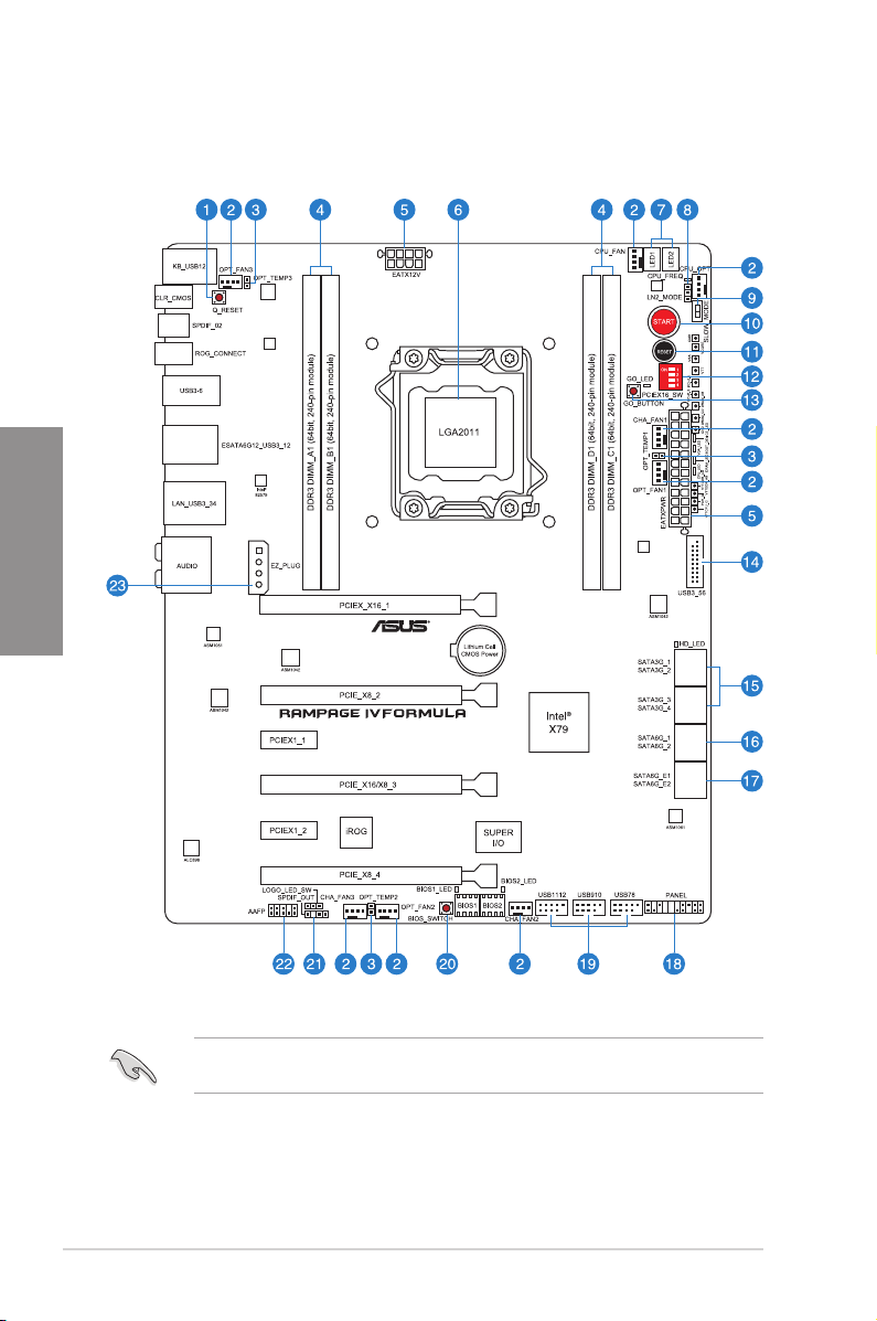
2.2.1 Motherboard layout
Chapter 2
Refer to
2.2.8 Internal connectors
information about rear panel connectors and internal connectors.
2-2 Chapter 2: Hardware information
and
2.3.10 Rear panel connection
for more
Page 27

Layout contents
Connectors/Jumpers/Slots Page
1. Q Reset button 2-16
2. CPU, chassis and power fan connectors (4-pin CPU_FAN;
4-pin CPU_OPT; 4-pin CHA_FAN1/2/3; 4-pin OPT_FAN1/2/3)
3. Thermal sensor cable connectors (2-pin OPT_TEMP1–3) 2-30
4. DDR3 DIMM slots channel A, B, C and D 2-5
5. ATX power connectors (24-pin EATXPWR; 8-pin EATX12V) 2-34
6. LGA2011 CPU socket 2-4
7. Debug LEDs 2-21
8. LN2 Mode jumper 2-26
9. Slow Mode Switch 2-17
10. Power-on Switch 2-14
11. Reset Switch 2-14
12. PCIe x16 Lane Switch 2-16
13. Go Button 2-15
14. USB 3.0 connector (20-1 pin USB3_56) 2-30
15. Intel X79 Serial ATA 3Gb/s connectors (7-pin SATA3G_1–4
[black])
16. Intel X79 Serial ATA 6Gb/s connectors (7-pin SATA6G_1/2 [red]) 2-27
17. ASMedia Serial ATA 6Gb/s connectors (7-pin SATA6G_E1/E2
[red])
18. System panel connector (20-8 pin PANEL) 2-37
19. USB 2.0 connectors (10-1 pin USB78; USB910; USB1112) 2-31
20. BIOS button 2-15
21. Digital audio connector (4-1 pin SPDIF_OUT) 2-32
22. Front panel audio connector (10-1 pin AAFP) 2-34
23. EZ Plug connector (4-pin EZ-PLUG) 2-36
2-33
Chapter 2
2-28
2-29
ROG RAMPAGE IV FORMULA 2-3
Page 28
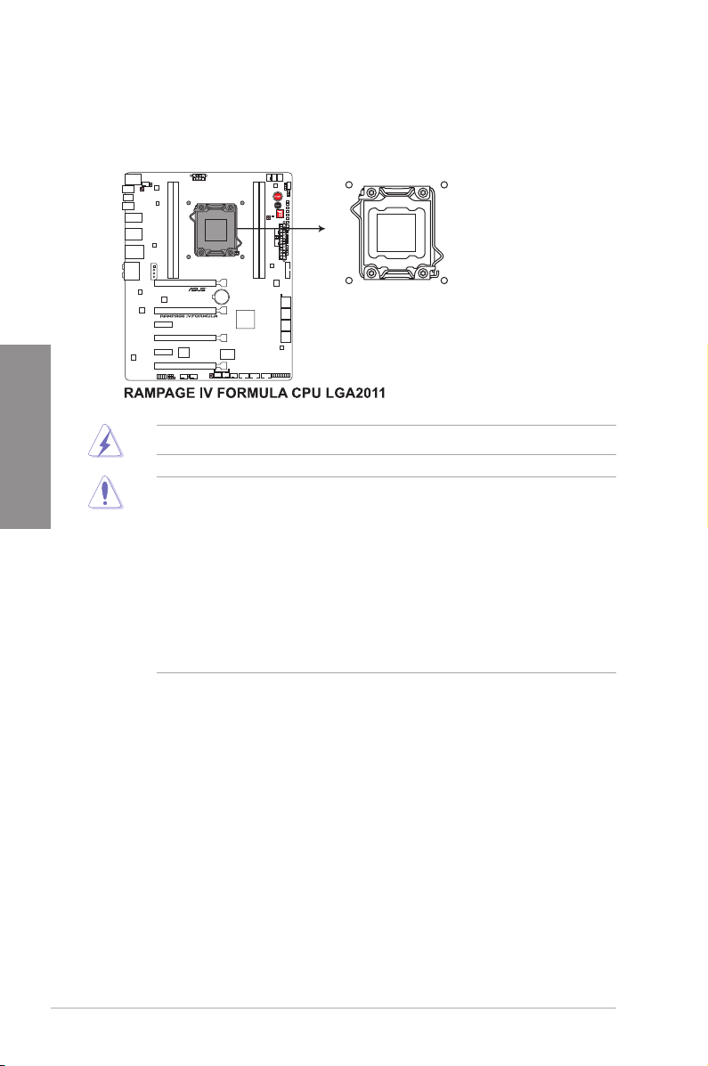
2.2.2 Central Processing Unit (CPU)
The motherboard comes with a surface mount LGA2011 socket designed for the Intel®
2nd Generation Core™ i7 Processor Extreme Edition.
Chapter 2
Ensure that all power cables are unplugged before installing the CPU.
• Upon purchase of the motherboard, ensure that the PnP cap is on the socket and
the socket contacts are not bent. Contact your retailer immediately if the PnP cap
is missing, or if you see any damage to the PnP cap/socket contacts/motherboard
components. ASUS will shoulder the cost of repair only if the damage is shipment/
transit-related.
• Keep the cap after installing the motherboard. ASUS will process Return Merchandise
Authorization (RMA) requests only if the motherboard comes with the cap on the
LGA2011 socket.
• The product warranty does not cover damage to the socket contacts resulting from
incorrect CPU installation/removal, or misplacement/loss/incorrect removal of the PnP
cap.
2-4 Chapter 2: Hardware information
Page 29
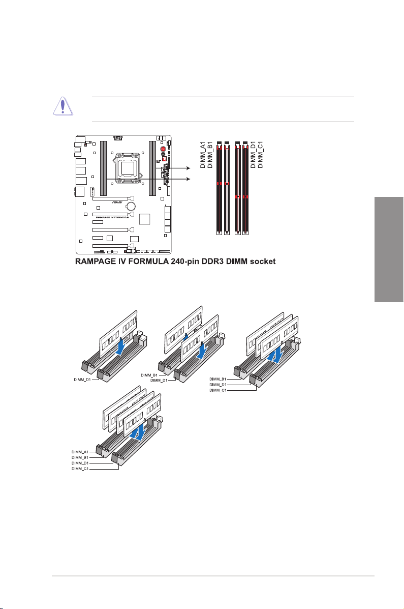
2.2.3 System memory
The motherboard comes with four Double Data Rate 3 (DDR3) Dual Inline Memory Modules
(DIMM) slots.
A DDR3 module is notched differently from a DDR or DDR2 module. DO NOT install a DDR
or DDR2 memory module to the DDR3 slot.
Recommended memory congurations
Chapter 2
ROG RAMPAGE IV FORMULA 2-5
Page 30

Memory congurations
You may install 1GB, 2GB, 4GB and 8GB unbuffered and non-ECC DDR3 DIMMs into the
DIMM sockets.
Chapter 2
• You may install varying memory sizes in Channel A, Channel B, Channel C and
Channel D. The system maps the total size of the lower-sized channel for the dualchannel, triple-channel and quad-channel conguration. Any excess memory from the
higher-sized channel is then mapped for single-channel operation.
• Due to CPU behavior, DDR3 2200/2000/1800 MHz memory module will run at DDR3
2133/1866/1600 MHz frequency as default.
• According to Intel® spec, the max. 32GB memory capacity can be supported with
DIMMs of 8GB (or above). ASUS will update QVL once the DIMMs are available on
the market.
• According to Intel CPU spec, DIMM voltage below 1.65V is recommended to protect
the CPU.
• Always install DIMMs with the same CAS latency. For optimum compatibility, we
recommend that you obtain memory modules from the same vendor.
• Due to the memory address limitation on 32-bit Windows OS, when you install 4GB
or more memory on the motherboard, the actual usable memory for the OS can be
about 3GB or less. For effective use of memory, we recommend that you do any of the
following:
- Use a maximum of 3GB system memory if you are using a 32-bit Windows OS.
- Install a 64-bit Windows OS when you want to install 4GB or more on the
motherboard.
For more details, refer to the Microsoft® support site at
http://support.microsoft.com/kb/929605/en-us.
• This motherboard does not support DIMMs made up of 512Mb (64MB) chips or less
(Memory chip capacity counts in Megabit, 8 Megabit/Mb = 1 Megabyte/MB).
• The default memory operation frequency is dependent on its Serial Presence Detect
(SPD), which is the standard way of accessing information from a memory module.
Under the default state, some memory modules for overclocking may operate at a
lower frequency than the vendor-marked value. To operate at the vendor-marked or at
a higher frequency, refer to section
frequency adjustment.
• For system stability, use a more efcient memory cooling system to support a full
memory load (4 DIMMs) or overclocking condition.
3.3 Extreme Tweaker menu
for manual memory
2-6 Chapter 2: Hardware information
Page 31

RAMPAGE IV FORMULA Motherboard Qualied Vendors Lists (QVL)
DDR3 1333 MHz capability
Vendors Part No. Size
A-DATA AD63I1B0823EV 2GB SS A-DATA 3CCA-1509A - - •
A-DATA AXDU1333GC2G9(XMP) 2GB SS - - 9-9-9-24 1.25~1.35 • •
A-DATA AD63I1C1624EV 4GB DS A-DATA 3CCA-1509A - - • •
A-DATA SU3U1333W8G9(XMP) 8GB DS ELPIDA J4208BASE-DJ-F - - • •
Apacer 78.01GC6.9L0 1GB SS Apacer AM5D5808DEJSBG 9 - •
Apacer 78.A1GC6.9L1 2GB DS Apacer AM5D5808FEQSBG 9 - •
Apacer 78.B1GDE.9L10C 4GB DS Apacer AM5D5908CEHSBG 9 - • •
CORSAIR TW3X4G1333C9A 4GB ( 2x 2GB ) DS - - 9-9-9-24 1.5 •
CORSAIR CMX8GX3M2A1333C9(XMP) 8GB ( 2x 4GB ) DS - - 9-9-9-24 1.5 •
CORSAIR CMX8GX3M4A1333C9 8GB(4 x 2GB) DS - - 9-9-9-24 1.5 •
Crucial BL25664BN1337.16FF(XMP) 2GB DS - - 7-7-7-24 1.65 •
ELPIDA EBJ41UF8BCF0-DJ-F 4GB DS ELPIDA J2108BCSE-DJ-F - - • •
G.SKILL F3-10600CL9D-4GBNT 4GB ( 2x 2GB ) DS G.SKILL D3 128M8CE9 2GB 9-9-9-24 1.5 • •
G.SKILL F3-10666CL7D-4GBRH(XMP) 4GB(2 x 2GB) DS - - 7-7-7-21 1.5 • •
G.SKILL F3-10666CL8D-4GBECO(XMP) 4GB(2 x 2GB) DS - - 8-8-8-24 1.35 • •
G.SKILL F3-10666CL9D-8GBRL 8GB ( 2x 4GB ) DS - - 9-9-9-24 1.5 •
G.SKILL F3-10666CL9D-8GBRL 8GB ( 2x 4GB ) DS - - 9-9-9-24 1.5 • •
G.SKILL F3-10666CL9D-8GBXL 8GB ( 2x 4GB ) DS - - 9-9-9-24 1.5 • •
GEIL GET316GB1333C9QC 16GB ( 4x 4GB ) DS - - 9-9-9-24 1.5 •
GEIL GG34GB1333C9DC 4GB ( 2x 2GB ) DS GEIL GL1L128M88BA115FW 9-9-9-24 1.3 • •
GEIL GG34GB1333C9DC 4GB ( 2x 2GB ) DS GEIL GL1L128M88BA15B 9-9-9-24 1.3 •
GEIL GVP34GB1333C9DC 4GB ( 2x 2GB ) DS - - 9-9-9-24 1.5 •
GEIL GB34GB1333C7DC 4GB(2 x 2GB) DS GEIL GL1L128M88BA15FW 7-7-7-24 1.5 • •
GEIL GG34GB1333C9DC 4GB(2 x 2GB) DS GEIL GL1L128M88BA12N 9-9-9-24 1.3 • •
GEIL GVP38GB1333C9DC 8GB ( 2x 4GB ) DS - - 9-9-9-24 1.5 • •
Hynix HMT112U6TFR8A-H9 1GB SS Hynix H5TC1G83TFR - - • •
Hynix HMT325U6BFR8C-H9 2GB SS Hynix H5TQ2G83BFR - - •
Hynix HMT125U6BFR8C-H9 2GB DS Hynix H5TQ1G83BFRH9C 9 - • •
Hynix HMT125U6TFR8A-H9 2GB DS Hynix H5TC1G83TFR - - •
KINGMAX FLFE85F-C8KL9 2GB SS KINGMAX KFC8FNLXF-DXX-15A - - • •
KINGMAX FLFE85F-B8KL9 2GB DS KINGMAX KFB8FNLXL-BNF-15A - - •
KINGMAX FLFF65F-C8KL9 4GB DS KINGMAX KFC8FNLXF-DXX-15A - - • •
KINGMAX FLFF65F-C8KM9 4GB DS Kingmax KFC8FNMXF-BXX-15A - - • •
KINGSTON KVR1333D3N9/1G 1GB SS Elpida J1108BDSE-DJ-F 9 1.5 • •
KINGSTON KVR1333D3S8N9/2G 2GB SS Micron IFD77 D9LGK - 1.5 • •
KINGSTON KVR1333D3N9/2G 2GB DS Kingston D1288JPNDPLD9U 9 1.5 • •
KINGSTON KVR1333D3N9K2/4G 4GB ( 2x 2GB ) DS KINGSTON D1288JEMFPGD9U - 1.5 • •
KINGSTON KVR1333D3E9S/4G 4GB DS Elpida J2108ECSE-DJ-F 9 1.5 • •
MICRON MT4JTF12864AZ-1G4D1 1GB SS Micron D9LGQ - - •
MICRON MT8JTF25664AZ-1G4D1 2GB SS Micron D9LGK - - • •
MICRON MT8JTF25664AZ-1G4D1 2GB SS Micron D9LGK - - •
MICRON MT8JTF25664AZ-1G4M1 2GB SS MICRON D9PFJ - - • •
MICRON MT16JTF51264AZ-1G4D1 4GB DS Micron D9LGK - - • •
OCZ OCZ3P1333LV3GK 3GB(3 x 1GB) SS - - 7-7-7 1.65 •
OCZ OCZ3G1333LV4GK 4GB ( 2x 2GB ) DS - - 9-9-9 1.65 •
OCZ OCZ3P1333LV4GK 4GB(2 x 2GB) DS - - 7-7-7 1.65 • •
OCZ OCZ3G1333LV8GK 8GB ( 2x 4GB ) DS - - 9-9-9 1.65 •
OCZ OCZ3G1333LV8GK 8GB ( 2x 4GB ) DS - - 9-9-9 1.65 •
PSC PC310600U-9-10-A0 1GB SS PSC A3P1GF3FGF - - • •
PSC PC310600U-9-10-B0 2GB DS PSC A3P1GF3FGF - - •
SAMSUNG M378B2873EH1-CH9 1GB SS SAMSUNG K4B1G0846E - - • •
SAMSUNG M378B2873FHS-CH9 1GB SS SAMSUNG K4B1G0846F - - • •
SAMSUNG M378B5773DH0-CH9 2GB SS SAMSUNG K4B2G08460 - - •
SAMSUNG M378B5673FH0-CH9 2GB DS SAMSUNG K4B1G0846F - - •
SAMSUNG M378B5273BH1-CH9 4GB DS SAMSUNG K4B2G0846B-HCH9 9 - • •
SAMSUNG M378B5273CH0-CH9 4GB DS SAMSUNG K4B2G0846C K4B2G0846C - •
SAMSUNG M378B5273DH0-CH9 4GB DS SAMSUNG K4B2G08460 - - • •
SAMSUNG M378B1G73AH0-CH9 8GB DS SAMSUNG K4B4G0846A-HCH9 - - • •
Transcend JM1333KLN-2G 2GB SS Transcend TK483PCW3 - - • •
SS/
Chip Brand Chip NO. Timing Voltage
DS
DIMM socket
support (Optional)
1 DIMM 4 DIMM
Chapter 2
ROG RAMPAGE IV FORMULA 2-7
Page 32

RAMPAGE IV FORMULA Motherboard Qualied Vendors Lists (QVL)
DDR3 1333 MHz capability
Vendors Part No. Size
Transcend TS256MLK64V3N ( 585541 ) 2GB SS Micron ICD77 D9LGK 9 - • •
Transcend TS256MLK64V3N (574206) 2GB SS Micron D9LGK 9 - • •
Transcend JM1333KLN-4G ( 583782 ) 4GB DS Transcend TK483PCW3 9 - •
Transcend JM1333KLN-4G 4GB DS Transcend TK483PCW3 - - • •
Transcend TS512MLK64V3N ( 585538 ) 4GB DS Micron IED27 D9LGK 9 - • •
ACTICA ACT1GHU64B8F1333S 1GB SS SAMSUNG K4B1G0846F - - • •
ACTICA ACT1GHU72C8G1333S 1GB SS SAMSUNG K4B1G0846F(ECC) - - • •
ACTICA ACT2GHU64B8G1333M 2GB DS Micron D9KPT - - • •
ACTICA ACT2GHU64B8G1333S 2GB DS SAMSUNG K4B1G0846F - - • •
ACTICA ACT2GHU72D8G1333M 2GB DS Micron D9KPT(ECC) - - • •
ACTICA ACT2GHU72D8G1333S 2GB DS SAMSUNG K4B1G0846F(ECC) - - • •
ACTICA ACT4GHU64B8H1333H 4GB DS Hynix H5TQ2G83AFR - - • •
Chapter 2
ACTICA ACT4GHU72D8H1333H 4GB DS Hynix H5TQ2G83AFR(ECC) - - • •
ATP AQ56M72E8BJH9S 2GB DS SAMSUNG K4B1G0846F(ECC) - - • •
ATP AQ12M72E8BKH9S 4GB DS SAMSUNG K4B2G0846C(ECC) - - • •
BUFFALO D3U1333-1G 1GB SS Elpida J1108BFBG-DJ-F - - • •
BUFFALO D3U1333-2G 2GB DS Elpida J1108BFBG-DJ-F - • •
BUFFALO D3U1333-4G 4GB DS NANYA NT5CB256M8BN-CG - • •
EK Memory EKM324L28BP8-I13 4GB(2 x 2GB) DS - - 9 - • •
Elixir M2F2G64CB88B7N-CG 2GB SS Elixir N2CB2G808N-CG - - • •
Elixir M2F2G64CB88D7N-CG 2GB SS Elixir M2CB2G8BDN-CG - - • •
Elixir M2F4G64CB8HB5N-CG 4GB DS Elixir N2CB2G808N-CG - - • •
Elixir M2F4G64CB8HD5N-CG 4GB DS Elixir M2CB2G8BDN-CG - - • •
KINGTIGER F10DA2T1680 2GB DS KINGTIGER KTG1333PS1208NST-C9 - - •
KINGTIGER KTG2G1333PG3 2GB DS - - - - • •
Patriot PSD32G13332 2GB DS Prtriot PM128M8D3BU-15 9 - • •
Patriot PGS34G1333LLKA 4GB(2 x 2GB) DS - - 7-7-7-20 1.7 • •
Patriot PG38G1333EL(XMP) 8GB DS - - - 1.5 • •
RiDATA C304627CB1AG22Fe 2GB DS RiDATA C304627CB1AG22Fe 9 - • •
RiDATA E304459CB1AG32Cf 4GB DS RiDATA E304459CB1AG32Cf 9 - • •
Silicon Power SP001GBLTE133S01 1GB SS NANYA NT5CB128M8AN-CG - - • •
Silicon Power SP001GBLTU1333S01 1GB SS NANYA NT5CB128M8AN-CG - - • •
Silicon Power SP001GBLTU133S02 1GB SS S-POWER 10YT3E5 9 - • •
Silicon Power SP002GBLTE133S01 2GB DS NANYA NT5CB128M8AN-CG - - • •
Silicon Power SP002GBLTU133S02 2GB DS S-POWER I0YT3E0 9 - • •
Team TXD31024M1333C7(XMP) 1GB SS Team T3D1288LT-13 7-7-7-21 1.75 • •
Team TXD31048M1333C7-D(XMP) 1GB SS Team T3D1288LT-13 7-7-7-21 1.75 • •
Team TXD32048M1333C7-D(XMP) 2GB DS Team T3D1288LT-13 7-7-7-21 1.5-1.6 • •
SS/
Chip Brand Chip NO. Timing Voltage
DS
DIMM socket support
(Optional)
1 DIMM 4 DIMM
RAMPAGE IV FORMULA Motherboard Qualied Vendors Lists (QVL)
DDR3 1600 MHz capability
DIMM socket support
Vendors Part No. Size SS/DS Chip Brand Chip NO. Timing Voltage
A-DATA AM2U16BC2P1 2GB SS A-DATA 3CCD-1509A - - •
A-DATA AX3U1600XC2G79(XMP) 2GB SS - - 9-9-9-24 1.6-1.8 •
A-DATA AM2U16BC4P2 4GB DS A-DATA 3CCD-1509A - - •
A-DATA AX3U1600GC4G9(XMP) 4GB DS - - - 1.55~1.75 •
A-DATA AX3U1600PC4G8(XMP) 4GB DS - - 8-8-8-24 1.55~1.75 •
CORSAIR HX3X12G1600C9(XMP) 12GB ( 6x 2GB ) DS - - 9-9-9-24 1.6 •
CORSAIR CMZ16GX3M4A1600C9(XMP) 16GB ( 4x 4GB ) DS - - 9-9-9-24 1.5 •
CORSAIR CMG4GX3M2A1600C6 4GB ( 2x 2GB ) DS - - 6-6-6-18 1.65 •
CORSAIR CMD4GX3M2B1600C8 4GB( 2x 2GB ) DS - - 8-8-8-24 1.65 •
CORSAIR CMX4GX3M2A1600C8(XMP) 4GB( 2x 2GB ) DS - - 8-8-8-24 1.65 •
CORSAIR CMP6GX3M3A1600C8(XMP) 6GB ( 3x 2GB ) DS - - 8-8-8-24 1.65 •
CORSAIR CMP6GX3M3A1600C8(XMP) 6GB ( 3x 2GB ) DS - - 8-8-8-24 1.65 •
CORSAIR CMX6GX3M3C1600C7(XMP) 6GB ( 3x 2GB ) DS - - 7-8-7-20 1.65 •
CORSAIR CMZ8GX3M2A1600C8(XMP) 8GB ( 2x 4GB ) DS - - 8-8-8-24 1.5 •
CORSAIR CMZ8GX3M2A1600C9(XMP) 8GB ( 2x 4GB ) DS - - 9-9-9-24 1.5 •
2-8 Chapter 2: Hardware information
(Optional)
1 DIMM 4 DIMM
Page 33

RAMPAGE IV FORMULA Motherboard Qualied Vendors Lists (QVL)
DDR3 1600 MHz capability
DIMM socket support
Vendors Part No. Size SS/DS Chip Brand Chip NO. Timing Voltage
Crucial BL12864BN1608.8FF(XMP) 2GB( 2x 1GB ) SS - - 8-8-8-24 1.65 •
Crucial BL25664BN1608.16FF(XMP) 2GB DS - - 8-8-8-24 1.65 •
G.SKILL F3-12800CL7Q-16GBXH(XMP) 16GB ( 4x 4GB ) DS - - 7-8-7-24 1.6 •
G.SKILL F3-12800CL9Q-16GBXL(XMP) 16GB ( 4x 4GB ) DS - - 9-9-9-24 1.5 •
G.SKILL F3-12800CL7D-4GBECO(XMP) 4GB(2 x 2GB) DS - - 7-8-7-24 - •
G.SKILL F3-12800CL8D-4GBRM(XMP) 4GB(2 x 2GB) DS - - 8-8-8-24 1.6 •
G.SKILL F3-12800CL9D-4GBECO(XMP) 4GB(2 x 2GB) DS - - 9-9-9-24 1.35 •
G.SKILL F3-12800CL7D-8GBRH(XMP) 8GB ( 2x 4GB ) DS - - 7-8-7-24 1.6 •
G.SKILL F3-12800CL9D-8GBRL(XMP) 8GB ( 2x 4GB ) DS - - 9-9-9-24 1.5 •
G.SKILL F3-12800CL9D-8GBSR2(XMP) 8GB ( 2x 4GB ) DS - - 9-9-9-24 1.25 •
G.SKILL F3-12800CL8D-8GBECO(XMP) 8GB ( 2x4GB ) DS - - 8-8-8-24 1.35 •
GEIL GET316GB1600C9QC(XMP) 16GB ( 4x 4GB ) DS - - 9-9-9-28 1.6 •
GEIL GUP34GB1600C7DC(XMP) 4GB ( 2x 2GB ) DS - - 7-7-7-24 1.6 •
KINGMAX FLGD45F-B8MF7(XMP) 1GB SS - - - - •
KINGSTON KHX1600C9D3K3/12GX(XMP) 12GB ( 3x 4GB ) DS - - 9 1.65 •
KINGSTON KHX1600C9D3K3/12GX(XMP) 12GB( 3x 4GB ) DS - - - 1.65 •
KINGSTON KHX1600C9D3K6/24GX(XMP) 24GB ( 6x 4GB ) DS - - 9 1.65 •
KINGSTON KHX1600C8D3K2/4GX(XMP) 4GB ( 2x 2GB ) DS - - 8 1.65 •
KINGSTON KHX1600C9D3K2/4GX(XMP) 4GB ( 2x 2GB ) DS - - - 1.65 •
KINGSTON KHX1600C9D3LK2/4GX(XMP) 4GB ( 2x 2GB ) DS - - - 1.65 •
KINGSTON KHX1600C9D3X2K2/4GX(XMP) 4GB ( 2x 2GB ) DS - - 9 1.65 •
KINGSTON KHX1600C9D3K3/6GX(XMP) 6GB ( 3x 2GB ) DS - - 9 1.65 •
KINGSTON KHX1600C9D3K3/6GX(XMP) 6GB ( 3x 2GB ) DS - - 9 1.65 •
KINGSTON KHX1600C9D3T1K3/6GX(XMP) 6GB ( 3x 2GB ) DS - - - 1.65 •
KINGSTON KHX1600C9D3T1K3/6GX(XMP) 6GB ( 3x 2GB ) DS - - 9 1.65 •
KINGSTON KHX1600C9D3P1K2/8G 8GB ( 2x 4GB ) DS - - 9 1.5 •
OCZ OCZ3BE1600C8LV4GK 4GB( 2x 2GB ) DS - - 8-8-8 1.65 •
OCZ OCZ3OB1600LV4GK 4GB(2 x 2GB) DS - - 9-9-9 1.65 • •
OCZ OCZ3X1600LV6GK(XMP) 6GB(3 x 2GB) DS - - 8-8-8 1.65 • •
OCZ OCZ3X1600LV6GK(XMP) 6GB(3 x 2GB) DS - - 8-8-8 1.65 •
Super Talent WP160UX4G9(XMP) 4GB(2 x 2GB) DS - - 9 - •
Super Talent WB160UX6G8(XMP) 6GB(3 x 2GB) DS - - - - •
Super Talent WB160UX6G8(XMP) 6GB(3 x 2GB) DS - - 8 - •
Transcend JM1600KLN-8GK 8GB ( 2x 4GB ) DS Transcend TK483PCW3 - - • •
AEXEA AXA3PS2G1600S18V(XMP) 2GB DS - - - 1.65 •
Asint SLZ3128M8-EGJ1D(XMP) 2GB DS Asint 3128M8-GJ1D - - •
EK Memory EKM324L28BP8-I16(XMP) 4GB( 2x 2GB ) DS - - 9 - •
EK Memory EKM324L28BP8-I16(XMP) 4GB(2 x 2GB) DS - - 9 - •
GoodRam GR1600D364L9/2G 2GB DS GoodRam GF1008KC-JN - - •
KINGTIGER KTG2G1600PG3(XMP) 2GB DS - - - - •
Mushkin 996805(XMP) 4GB ( 2x 2GB ) DS - - 6-8-6-24 1.65 •
Mushkin 998805(XMP) 6GB ( 3x 2GB ) DS - - 6-8-6-24 1.65 •
Patriot PX7312G1600LLK(XMP) 12GB ( 3x 4GB ) DS - - 8-9-8-24 1.65 •
Patriot PGS34G1600LLKA2 4GB ( 2x 2GB ) DS - - 8-8-8-24 1.7 •
Patriot PGS34G1600LLKA 4GB( 2x 2GB ) DS - - 7-7-7-20 1.7 •
PATRIOT PGS34G1600LLKA 4GB(2 x 2GB) DS - - 7-7-7-20 1.7 •
Patriot PVV38G1600LLK(XMP) 8GB ( 2x 4GB ) DS - - 8-9-8-24 1.65 •
Patriot PX538G1600LLK(XMP) 8GB ( 2x 4GB ) DS - - 8-9-8-24 1.65 •
Team TXD31024M1600C8-D(XMP) 1GB SS Team T3D1288RT-16 8-8-8-24 1.65 •
Team TXD32048M1600C7-L(XMP) 2GB DS Team T3D1288LT-16 7-7-7-24 1.65 •
Team TXD32048M1600HC8-D(XMP) 2GB DS Team T3D1288RT-16 8-8-8-24 1.65 •
(Optional)
1 DIMM 4 DIMM
Chapter 2
ROG RAMPAGE IV FORMULA 2-9
Page 34

RAMPAGE IV FORMULA Motherboard Qualied Vendors Lists (QVL)
DDR3 1800 MHz capability
Vendors Part No. Size SS/DS Chip Brand Chip NO. Timing Voltage
G.SKILL F3-14400CL9D-4GBRL(XMP) 4GB(2 x 2GB) DS - - 9-9-9-24 1.6 • •
RAMPAGE IV FORMULA Motherboard Qualied Vendors Lists (QVL)
DDR3 1866 MHz capability
Vendors Part No. Size SS/DS Chip Brand Chip NO. Timing Voltage
Chapter 2
A-DATA AX3U1866GC2G9B(XMP) 2GB SS - - 9-11-9-27 1.55~1.75 • •
A-DATA AX3U1866GC4G9B(XMP) 4GB DS - - 9-11-9-27 1.55~1.75 • •
CORSAIR CMZ8GX3M2A1866C9(XMP) 8GB ( 2x 4GB ) DS - - 9-10-9-27 1.5 • •
G.SKILL F3-14900CL9Q-16GBXL(XMP) 16GB ( 4x 4GB ) DS - - 9-10-9-28 1.5 • •
G.SKILL F3-15000CL9D-4GBTD(XMP) 4GB(2 x 2GB) DS - - 9-9-9-24 1.65 •
G.SKILL F3-14900CL9D-8GBSR(XMP) 8GB ( 2x 4GB ) DS - - 9-10-9-28 1.5 • •
G.SKILL F3-14900CL9Q-8GBFLD(XMP) 8GB ( 2x 4GB ) DS - - 9-9-9-24 1.6 • •
KINGSTON KHX1866C9D3T1K3/3GX(XMP) 3GB ( 3x 1GB ) SS - - - 1.65 • •
OCZ OCZ3P1866C9LV6GK 6GB(3 x 2GB) DS - - 9-9-9 1.65 • •
OCZ OCZ3RPR1866C9LV6GK 6GB(3 x 2GB) DS - - 9-9-9 1.65 •
Patriot PXD34G1866ELK(XMP) 4GB ( 2x 2GB ) SS - - 9-9-9-24 1.65 • •
Patriot PXD38G1866ELK(XMP) 8GB ( 2x 4GB ) DS - - 9-11-9-27 1.65 • •
Team TXD32048M1866C9(XMP) 2GB DS Team T3D1288RT-16 9-9-9-24 1.65 • •
RAMPAGE IV FORMULA Motherboard Qualied Vendors Lists (QVL)
DDR3 2000 MHz capability
Vendors Part No. Size SS/DS Chip Brand Chip NO. Timing Voltage
A-DATA AX3U2000GB2G9B(XMP) 2GB DS - - 9-11-9-27 1.55~1.75 • •
A-DATA AX3U2000GC4G9B(XMP) 4GB DS - - 9-11-9-27 1.55~1.75 •
Apacer 78.AAGD5.9KD(XMP) 6GB(3 x 2GB) DS - - 9-9-9-27 - • •
CORSAIR CMT6GX3M3A2000C8(XMP) 6GB ( 3x 2GB ) DS - - 8-9-8-24 1.65 •
Crucial BL12864BE2009.8SFB3(EPP) 1GB SS - - 9-9-9-28 2 •
KINGSTON KHX2000C9AD3T1K3/6GX(XMP) 6GB ( 3x 2GB ) DS - - 9 1.65 • •
Transcend TX2000KLN-8GK (388375)(XMP) 4GB DS - - - 1.6 • •
AEXEA AXA3ES2G2000LG28V(XMP) 2GB DS - - - 1.65 • •
AEXEA AXA3ES4GK2000LG28V(XMP) 4GB ( 2x 2GB ) DS - - - 1.65 • •
Gingle FA3URSS673A801A 2GB DS - - 9-9-9-24 - • •
Patriot PX7312G2000ELK(XMP) 12GB ( 3x 4GB ) DS - - 9-11-9-27 1.65 •
Patriot PV736G2000ELK(XMP) 6GB ( 3x 2GB ) DS - - 7-7-7-20 1.65 •
Patriot PVT36G2000LLK(XMP) 6GB(3 x 2GB) DS - - 8-8-8-24 1.65 •
Silicon Power SP002GBLYU200S02(XMP) 2GB DS - - - - •
Team TXD32048M2000C9(XMP) 2GB DS Team T3D1288RT-20 9-9-9-24 1.5 • •
Team TXD32048M2000C9-L(XMP) 2GB DS Team T3D1288LT-20 9-9-9-24 1.5 • •
Team TXD32048M2000C9-L(XMP) 2GB DS Team T3D1288RT-20 9-9-9-24 1.6 • •
DIMM socket support (Optional)
1 DIMM 4 DIMM
DIMM socket support
(Optional)
1 DIMM 4 DIMM
DIMM socket support
(Optional)
1 DIMM 4 DIMM
2-10 Chapter 2: Hardware information
Page 35

RAMPAGE IV FORMULA Motherboard Qualied Vendors Lists (QVL)
DDR3 2133 MHz capability
Vendors Part No. Size SS/DS Chip Brand
A-DATA 8154A 1044(XMP) 2GB SS - - 9-9-9-24 1.55-1.75 • •
A-DATA AX3U2133C2G9B(XMP) 2GB SS - - 9-11-9-27 1.55~1.75 • •
A-DATA AX3U2133GC2G9B(XMP) 2GB SS - - 9-9-9-24 1.55-1.75 •
Apacer 78.BAGE4.AFD0C(XMP) 8GB ( 2x 4GB ) DS - - 9-9-9-24 - • •
CORSAIR CMT4GX3M2A2133C9(XMP) 4GB ( 2x 2GB ) DS - - 9-10-9-24 1.65 • •
CORSAIR CMT4GX3M2B2133C9(XMP) 4GB ( 2x 2GB ) DS - - 9-10-9-27 1.5 • •
G.SKILL F3-17000CL9Q-16GBXLD(XMP) 16GB ( 4x 4GB ) DS - - 9-11-9-28 1.65 • •
G.SKILL F3-17066CL9Q-16GBTDD(XMP) 16GB ( 4x 4GB ) DS - - 9-9-9-24 1.65 • •
G.SKILL F3-17066CL9D-8GBPID(XMP) 8GB ( 2x 4GB ) DS - - 9-9-9-24 1.65 •
GEIL GE34GB2133C9DC(XMP) 4GB(2 x 2GB) DS - - 9-9-9-28 1.65 • •
KINGSTON KHX2133C9AD3T1K2/4GX(XMP) 4GB ( 2x 2GB ) DS - - - 1.65 •
KINGSTON KHX2133C9AD3T1K2/4GX(XMP) 4GB ( 2x 2GB ) DS - - 9 1.65 • •
KINGSTON KHX2133C9AD3W1K2/4GX(XMP) 4GB ( 2x 2GB ) DS - - 9 1.65 • •
KINGSTON KHX2133C9AD3X2K2/4GX(XMP) 4GB ( 2x 2GB ) DS - - 9 1.65 • •
KINGSTON KHX2133C9AD3X2K2/4GX(XMP) 4GB ( 2x 2GB ) DS - - 9-9-9-24 1.65 • •
KINGSTON KHX2133C9AD3T1FK4/8GX(XMP) 8GB ( 4x 2GB ) DS - - 9 1.65 • •
OCZ OCZ3XTEP2133C9LV4GK 2GB DS - - 7-7-7-20 1.65 •
Patriot PVV34G2133C9K(XMP) 4GB ( 2x 2GB ) DS - - 9-11-9-27 1.66 • •
Chip
NO.
Timing Voltage
DIMM socket support
(Optional)
1 DIMM 4 DIMM
RAMPAGE IV FORMULA Motherboard Qualied Vendors Lists (QVL)
DDR3 2200 MHz capability
Chapter 2
Vendors Part No. Size SS/DS Chip Brand Chip NO. Timing Voltage
G.SKILL F3-17600CL7D-4GBFLS(XMP) 4G ( 2x 2G ) DS - - 7-10-10-28 1.65 • •
G.SKILL F3-17600CL8D-4GBPS(XMP) 4GB(2 x 2GB) DS - - 8-8-8-24 1.65 • •
G.SKILL F3-17600CL9D-4GBTDS(XMP) 4GB(2 x 2GB) DS - - 9-9-9-24 1.65 • •
GEIL GET34GB2200C9DC(XMP) 4GB ( 2x 2GB ) DS - - 9-10-9-28 1.65 • •
GEIL GET38GB2200C9ADC(XMP) 8GB ( 2x 4GB ) DS - - 9-11-9-28 1.65 • •
KINGMAX FLKE85F-B8KHA(XMP) 4G ( 2x 2G ) DS - - - 1.5~1.7 • •
KINGMAX FLKE85F-B8KJAA-FEIS(XMP) 4GB ( 2x 2GB ) DS Kingmax N/A - - • •
DIMM socket support (Optional)
1 DIMM 4 DIMM
RAMPAGE IV FORMULA Motherboard Qualied Vendors Lists (QVL)
DDR3 2400 MHz capability
Vendors Part No. Size SS/DS Chip Brand Chip NO. Timing Voltage
A-DATA AX3U2400GC4G10(XMP) 4GB DS - - 10-11-10-30 1.65 •
CORSAIR CMGTX8(XMP) 8GB ( 4x 2GB ) SS - - 10-12-10-30 1.65 • •
CORSAIR CMGTX3(XMP) 2GB DS - - 9-11-9-27 1.65 • • •
G.Skill F3-19200CL11Q-16GBZHD(XMP) 16GB ( 4x 4GB ) DS - - 11-11-11-31 1.65 • •
GEIL GOC316GB2400C11QC(XMP) 16GB ( 4x 4GB ) DS - - 11-11-11-30 1.65 • •
Transcend TX2400KLU-4GK (381850)(XMP) 2GB DS - - - 1.65 • • •
Transcend TX2400KLU-4GK(374243)(XMP) 2GB DS - - - 1.65 • • •
Patriot PVV34G2400C9K(XMP) 4GB ( 2x 2GB ) DS - - 9-11-9-27 1.66 •
ROG RAMPAGE IV FORMULA 2-11
DIMM socket support (Optional)
1 DIMM 2 DIMM 4 DIMM
Page 36

2.2.4 Expansion slots
Chapter 2
Slot No. Slot Description
1 PCIe 3.0 x16_1 slot
2 PCIe 3.0 x8_2 slot
3 PCIe 2.0 x1_1 slot
4 PCIe 3.0 x16/8_3 slot
5 PCIe 2.0 x1_2 slot
6 PCIe 3.0 x8_4 slot
Ensure to unplug the power cord before adding or removing expansion cards. Failure to do
so may cause you physical injury and damage motherboard components.
• Refer to the following conguration table for installation.
PCIe x16
Slot #
1
2
4
6
• We recommend that you provide sufcient power when running
CrossFireX™ or SLI mode. See page 2-34 for details.
• While running at heavy loaded four VGA cards, ensure to plug in the 6-pin extra PCIe
power supply for stability.
• Connect a chassis fan to the motherboard connector labeled CHA_FAN1/2/3 when
using multiple graphics cards for better thermal environment.
2-12 Chapter 2: Hardware information
Single
VGA
SLI/CF
3-way
SLI/CFX
SLI/CFX
x16 x16 x16 x16
— — x8 x8
— x16 x16 x8
— — — x8
Quad
Page 37

IRQ assignments for this motherboard
A B C D E F G H
PCIE_X16_1 shared – – – – – – –
PCIE_X8_2 shared – – – – – – –
PCIE_X16/X8_3 shared – – – – – – –
PCIE_X8_4 shared – – – – – – –
PCIE_X1_1 shared – – – – – – –
PCIE_X1_2 – shared – – – – – –
ASM USB3#1 – shared – – – – – –
ASM USB3#2 – – – shared – – – –
ASM USB3#3 shared – – – – – – –
ASM SATA6#1 – shared – – – – – –
Intel 82579V – – shared – – – – –
ASM SATA6#2 – – – shared – – – –
EHCI#0 – – – – – – – shared
EHCI#1 – – – – – shared – –
High Denition Audio – – – – – – shared –
SATA #0 – – shared – – – – –
SATA #0 – – – – shared – – –
Chapter 2
ROG RAMPAGE IV FORMULA 2-13
Page 38

2.2.5 Onboard switches
Onboard switches allow you to ne-tune performance when working on a bare or open-
case system. This is ideal for overclockers and gamers who continually change settings to
enhance system performance.
1. Power-on switch
Press the power-on switch to wake/power up the system.
Chapter 2
2. Reset switch
Press the reset switch to reboot the system.
2-14 Chapter 2: Hardware information
Page 39

3. GO button
Press the GO button before POST to enable MemOK! or press it to quickly load the
preset prole (GO_Button le) for temporary overclocking when in OS.
4. BIOS button
The motherboard comes with two BIOS. Press the BIOS button to switch BIOS and
load different BIOS settings. The nearby BIOS LEDs indicate the BIOS you are using.
Chapter 2
ROG RAMPAGE IV FORMULA 2-15
Page 40

5. PCIe x16 Lane switch
These slide switches allows you to enable and disable the corresponding PCIe x16
slots. When one of the installed PCIe x16 cards is out of order, you can use the slide
switch to nd out the faulty one without removing the cards.
Chapter 2
6. Q reset button
If the LN2_Mode jumper does not work and your CPU cannot resume function, press
the Q reset button to temporarily stop the power supply to the CPU and help the CPU
recover from a frozen condition.
2-16 Chapter 2: Hardware information
Page 41

7. Slow Mode Switch
Slow Mode Switch is employed during LN2 benching. Some processors have a small
optimum temperature range to run at their highest frequency. Warmer or colder yields
instability at this frequency. For example, a certain processor may need -80C loaded
in order to run 5.8GHz, which means about -75C idle in order to stay stable at 5.8GHz.
Going colder or warmer crashes. It will however remain stable at slower frequencies
at much colder or warmer temperatures. Once it comes out of a heavy load while
transitioning over to a light load, when the temperature does not warm fast enough,
it may crash. To over-come this simply flip the switch over to “slow” the processor
instantaneously. Switching over to Slow-Mode during critical moments when
Temperature/Max Frequency alignment is off-synch saves you a lot of crashes, even
when trying to boot into the OS at cold temperatures.
The Slow mode switch is workable only when LN2 mode jumper is been set to enable.
(please see 2-26)
Chapter 2
ROG RAMPAGE IV FORMULA 2-17
Page 42

2.2.6 Onboard LEDs
The motherboard comes with a set of LEDs that indicate the voltage conditions of CPU, memory,
northbridge and southbridge. You may adjust the voltages in BIOS. There are also an LED for
hard disk drive activity and an onboard switch for power status. For more information about
voltage adjustment, refer to 3.3 Extreme Tweaker menu.
1. Voltiminder LED II
Voltiminder LED II provides not only many measurement spots for various voltages but
LEDs indicating which voltage is being polled. This is especially useful when debugging
overclock failures. Voltiminder LED II consists of the following LED set:
DRAM_AB, PCH_1.5V, PCH_1.1V, CPU_PLL, CPU_VTT, CPU_VSA, CPU GND_U
and
light up, it tells you that your system does not like the setting for CPU VTT.
Chapter 2
CPU_FREQ
DRAM_CD
. For example, when you fail to post and see the LED for CPU_VTT
,
2-18 Chapter 2: Hardware information
Page 43

2. Hard Disk LED
The hard disk LED is designed to indicate the hard disk activity. It blinks when data
is being written into or read from the hard disk drive. The LED does not light up when
there is no hard disk drive connected to the motherboard or when the hard disk drive
does not function.
3. BIOS LED
The BIOS LEDs help indicate the BIOS activity. Press the BIOS button to switch
between BIOS1 and BIOS2 and the LED lights up when the corresponding BIOS is in
use.
Chapter 2
ROG RAMPAGE IV FORMULA 2-19
Page 44

4. GO LED
Blinking: Indicates that MemOK! is enabled before POST.
Lighting: Indicates that the system loads the preset prole (GO_Button le) for
temporary overclocking when in OS.
Chapter 2
5. Q LED
Q LEDs check key components (CPU, DRAM, VGA card, and booting devices) in
sequence during motherboard booting process. If an error is found , the corresponding
LED will continue lighting until the problem is solved. This user-friendly design provides
an intuitional way to locate the root problem within a second.
2-20 Chapter 2: Hardware information
Page 45

6. Power LED
The motherboard comes with a power-on switch that lights up to indicate that the
system is ON, in sleep mode, or in soft-off mode. This is a reminder that you should
shut down the system and unplug the power cable before removing or plugging in any
motherboard component. The illustration below shows the location of the onboard
power-on switch.
7. Debug LEDs
The Debug LED design provides you the 2-digit display, allowing you to know the
system status. Refer to the Debug table below for details.
Chapter 2
ROG RAMPAGE IV FORMULA 2-21
Page 46

Debug table
Code Description
00
01
02
03
04
05
06
07
08
09
0A
Chapter 2
0B
0C – 0D
0E
0F
10
11 – 14
15 – 18
19 – 1C
1D – 2A
2B – 2F
30
31
32 – 36
37 – 3A
Not used
Power on. Reset type detection (soft/hard).
AP initialization before microcode loading
System Agent initialization before microcode loading
PCH initialization before microcode loading
OEM initialization before microcode loading
Microcode loading
AP initialization after microcode loading
System Agent initialization after microcode loading
PCH initialization after microcode loading
OEM initialization after microcode loading
Cache initialization
Reserved for future AMI SEC error codes
Microcode not found
Microcode not loaded
PEI Core is started
Pre-memory CPU initialization is started
Pre-memory System Agent initialization is started
Pre-memory PCH initialization is started
OEM pre-memory initialization codes
Memory initialization
Reserved for ASL (see ASL Status Codes section below)
Memory Installed
CPU post-memory initialization
Post-Memory System Agent initialization is started
2-22 Chapter 2: Hardware information
Page 47

Debug table (continued)
Code Description
3B – 3E
3F – 4E
4F
50 – 53
54
55
56
57
58
59
5A
5B
5C – 5F
E0
E1
E2
E3
E4 – E7
E8
E9
EA
EB
EC – EF
F0
F1
F2
F3
F4
F5-F7
F8
F9
FA
FB-FF
60
61
62
63 – 67
68
69
6A
6B – 6F
70
Post-Memory PCH initialization is started
OEM post memory initialization codes
DXE IPL is started
Memory initialization error. Invalid memory type or incompatible memory
speed
Unspecied memory initialization error
Memory not installed
Invalid CPU type or Speed
CPU mismatch
CPU self test failed or possible CPU cache error
CPU micro-code is not found or micro-code update is failed
Internal CPU error
Reset PPI is not available
Reserved for future AMI error codes
S3 Resume is stared (S3 Resume PPI is called by the DXE IPL)
S3 Boot Script execution
Video repost
OS S3 wake vector call
Reserved for future AMI progress codes
S3 Resume Failed
S3 Resume PPI not Found
S3 Resume Boot Script Error
S3 OS Wake Error
Reserved for future AMI error codes
Recovery condition triggered by rmware (Auto recovery)
Recovery condition triggered by user (Forced recovery)
Recovery process started
Recovery rmware image is found
Recovery rmware image is loaded
Reserved for future AMI progress codes
Recovery PPI is not available
Recovery capsule is not found
Invalid recovery capsule
Reserved for future AMI error codes
DXE Core is started
NVRAM initialization
Installation of the PCH Runtime Services
CPU DXE initialization is started
PCI host bridge initialization
System Agent DXE initialization is started
System Agent DXE SMM initialization is started
System Agent DXE initialization (System Agent module specic)
PCH DXE initialization is started
Chapter 2
ROG RAMPAGE IV FORMULA 2-23
Page 48

Debug table (continued)
Code Description
71
72
73 – 77
78
79
7A – 7F
80 – 8F
90
91
92
93
Chapter 2
94
95
96
97
98
99
9A
9B
9C
9D
9E – 9F
A0
A1
A2
A3
A4
A5
A6
A7
A8
A9
AA
AB
AC
AD
AE
AF
B0
B1
B2
B3
PCH DXE SMM initialization is started
PCH devices initialization
PCH DXE Initialization (PCH module specic)
ACPI module initialization
CSM initialization
Reserved for future AMI DXE codes
OEM DXE initialization codes
Boot Device Selection (BDS) phase is started
Driver connecting is started
PCI Bus initialization is started
PCI Bus Hot Plug Controller Initialization
PCI Bus Enumeration
PCI Bus Request Resources
PCI Bus Assign Resources
Console Output devices connect
Console input devices connect
Super IO Initialization
USB initialization is started
USB Reset
USB Detect
USB Enable
Reserved for future AMI codes
IDE initialization is started
IDE Reset
IDE Detect
IDE Enable
SCSI initialization is started
SCSI Reset
SCSI Detect
SCSI Enable
Setup Verifying Password
Start of Setup
Reserved for ASL (see ASL Status Codes section below)*
Setup Input Wait
Reserved for ASL (see ASL Status Codes section below)
Ready To Boot event
Legacy Boot event
Exit Boot Services event
Runtime Set Virtual Address MAP Begin
Runtime Set Virtual Address MAP End
Legacy Option ROM Initialization
System Reset
2-24 Chapter 2: Hardware information
Page 49

Debug table (continued)
Code Description
B4
B5
B6
B7
B8– BF
C0– CF
D0
D1
D2
D3
D4
D5
D6
D7
D8
D9
DA
DB
DC
*ASL Status Codes
Status Code Description
01
02
03
04
05
10
20
30
40
AC
AA
USB hot plug
PCI bus hot plug
Clean-up of NVRAM
Conguration Reset (reset of NVRAM settings)
Reserved for future AMI codes
OEM BDS initialization codes
CPU initialization error
System Agent initialization error
PCH initialization error
Some of the Architectural Protocols are not available
PCI resource allocation error. Out of Resources
No Space for Legacy Option ROM
No Console Output Devices are found
No Console Input Devices are found
Invalid password
Error loading Boot Option (LoadImage returned error)
Boot Option is failed (StartImage returned error)
Flash update is failed
Reset protocol is not available
System is entering S1 sleep state
System is entering S2 sleep state
System is entering S3 sleep state
System is entering S4 sleep state
System is entering S5 sleep state
System is waking up from the S1 sleep state
System is waking up from the S2 sleep state
System is waking up from the S3 sleep state
System is waking up from the S4 sleep state
System has transitioned into ACPI mode. Interrupt controller is in APIC mode
System has transitioned into ACPI mode. Interrupt controller is in APIC mode
Chapter 2
ROG RAMPAGE IV FORMULA 2-25
Page 50

2.2.7 Jumper
1. LN2 Mode Jumper (3-pin LN2)
With LN2 mode activated, the ROG motherboard is optimized to remedy the cold-
boot bug during POST at an extremely low temperature and help the system boot
successfully.
Chapter 2
2-26 Chapter 2: Hardware information
Page 51

2.2.8 Internal connectors
1. Intel® X79 Serial ATA 6.0 Gb/s connectors (7-pin SATA6G_1/2 [red])
These connectors connect to Serial ATA 6.0 Gb/s hard disk drives via Serial ATA 6.0
Gb/s signal cables.
If you installed Serial ATA hard disk drives, you can create a RAID 0, 1, 5, and 10
conguration with the Intel® Rapid Storage Technology through the onboard Intel® X79
chipset.
•
These connectors are set to [AHCI Mode] by default. If you intend to create a Serial
ATA RAID set using these connectors, set the SATA Mode item in the BIOS to [RAID
Mode]. Refer to section 3.5.4 SATA Conguration for details.
• Before creating a RAID set, refer to section 4.4 RAID congurations or the manual
bundled in the motherboard support DVD.
•
When using NCQ, set the
3.5.4 SATA Conguration
•
You must install Windows® XP Service Pack 3 or later versions before using Serial
ATA hard disk drives. The Serial ATA RAID feature is available only if you are using
Windows® XP SP3 or later versions.
SATA Mode
for details.
in the BIOS to [AHCI Mode]. Refer to section
Chapter 2
ROG RAMPAGE IV FORMULA 2-27
Page 52

2. Intel® X79 Serial ATA 3.0 Gb/s connectors (7-pin SATA3G_1–4 [black])
These connectors connect to Serial ATA 3.0 Gb/s hard disk drives and optical disc
drives via Serial ATA 3.0 Gb/s signal cables.
If you installed Serial ATA hard disk drives, you can create a RAID 0, 1, 5, and 10
conguration with the Intel® Rapid Storage Technology through the onboard Intel® X79
chipset.
Chapter 2
•
These connectors are set to [AHCI Mode] by default. If you intend to create a Serial
ATA RAID set using these connectors, set the SATA Mode item in the BIOS to [RAID
Mode]. Refer to section 3.5.4 SATA Conguration for details.
• Before creating a RAID set, refer to section 4.4 RAID congurations or the manual
bundled in the motherboard support DVD.
•
When using NCQ, set the
3.5.4 SATA Conguration
•
You must install Windows® XP Service Pack 3 or later versions before using Serial
ATA hard disk drives. The Serial ATA RAID feature is available only if you are using
Windows® XP SP3 or later versions.
2-28 Chapter 2: Hardware information
SATA Mode
for details.
in the BIOS to [AHCI Mode]. Refer to section
Page 53

3. ASMedia® Serial ATA 6.0 Gb/s connectors (7-pin SATA6G_E1/E2 [red])
These connectors connect to Serial ATA 6.0 Gb/s hard disk drives via Serial ATA 6.0
Gb/s signal cables.
• The SATA6G_E1/E2 (red) connectors are for data drives only. ATAPI device is not
supported.
•
You must install Windows® XP Service Pack 3 or later versions before using Serial ATA
hard disk drives.
•
When using NCQ, set the
Refer to section
3.5.6 Onboard Devices Conguration
ASM1061 Storage Controller
item in the BIOS to [ACHI].
for details.
Chapter 2
ROG RAMPAGE IV FORMULA 2-29
Page 54

4. USB 3.0 connector (20-1 pin USB3_56)
This connector is for the additional USB 3.0 ports, and complies with the USB 3.0
specicaton that supports up to 4.8Gbps connection speed. If the USB 3.0 front panel
cable is available from your system chassis, with this USB 3.0 connector, you can have
a front panel USB 3.0 solution.
Chapter 2
5. Thermal sensor cable connectors (2-pin OPT_TEMP1/2/3)
These connectors are for temperature monitoring. Connect the thermal sensor cables
to these connectors and place the other ends to the devices which you want to monitor
temperature. The optional fan1/2/3 can work with the temperature sensors for a better
cooling effect.
The USB 3.0 module is purchased separately.
Enable OPT FAN1/2/3 overheat protection in BIOS if you connect thermal sensor cables
to these connectors.
The thermal sensor cables are purchased separately.
2-30 Chapter 2: Hardware information
Page 55

6. USB 2.0 connectors (10-1 pin USB78; USB910; USB1112)
These connectors are for USB 2.0 ports. Connect the USB module cable to any of
these connectors, then install the module to a slot opening at the back of the system
chassis. These USB connectors comply with USB 2.0 specication that supports up to
480 Mbps connection speed.
Never connect a 1394 cable to the USB connectors. Doing so will damage the motherboard!
You can connect the front panel USB cable to the ASUS Q-Connector (USB, blue) rst, and
then install the Q-Connector (USB) to the USB connector onboard if your chassis supports
front panel USB ports.
The USB 2.0 module is purchased separately.
Chapter 2
ROG RAMPAGE IV FORMULA 2-31
Page 56

7. Digital audio connector (4-1 pin SPDIF_OUT)
This connector is for an additional Sony/Philips Digital Interface (S/PDIF) port. Connect
the S/PDIF Out module cable to this connector, then install the module to a slot opening
at the back of the system chassis.
Chapter 2
The S/PDIF module is purchased separately.
2-32 Chapter 2: Hardware information
Page 57

8. CPU, chassis, and power fan connectors
(4-pin CPU_FAN; 4-pin CPU_OPT; 4-pin CHA_FAN1/2/3; 4-pin OPT_FAN1/2/3)
Connect the fan cables to the fan connectors on the motherboard, ensuring that the
black wire of each cable matches the ground pin of the connector.
Do not forget to connect the fan cables to the fan connectors. Insufcient air ow inside the
system may damage the motherboard components. These are not jumpers! Do not place
jumper caps on the fan connectors!
• The CPU_FAN connector supports the CPU fan of maximum 1A (12 W) fan power.
• Only the CPU_FAN, CHA_FAN 1, CHA_FAN 2 and CHA_FAN 3 connectors support
the ASUS FAN Xpert feature.
• If you install two VGA cards, we recommend that you plug the rear chassis fan cable
to the motherboard connector labeled CHA_FAN1 or CHA_FAN2 for better thermal
environment.
Chapter 2
ROG RAMPAGE IV FORMULA 2-33
Page 58

9. Front panel audio connector (10-1 pin AAFP)
This connector is for a chassis-mounted front panel audio I/O module that supports
either HD Audio or legacy AC`97 audio standard. Connect one end of the front panel
audio I/O module cable to this connector.
Chapter 2
10. ATX power connectors (24-pin EATXPWR; 8-pin EATX12V)
These connectors are for ATX power supply plugs. The power supply plugs are
designed to t these connectors in only one orientation. Find the proper orientation and
push down rmly until the connectors completely t.
• We recommend that you connect a high-denition front panel audio module to this
connector to avail of the motherboard’s high-denition audio capability.
• If you want to connect a high-denition front panel audio module to this connector, setIf you want to connect a high-denition front panel audio module to this connector, set
the
Front Panel Type
front panel audio module to this connector, set the item to
connector is set to
item in the BIOS setup to
.
[HD]
if you want to connect an AC'97
[HD];
. By default, this
[AC97]
2-34 Chapter 2: Hardware information
Page 59

• For a fully congured system, we recommend that you use a power supply unit
(PSU) that complies with ATX 12 V Specication 2.0 (or later version) and provides a
minimum power of 350 W.
• Do not forget to connect the 8-pin EATX12 V power plug; otherwise, the system will
not boot.
• Use of a PSU with a higher power output is recommended when conguring a system
with more power-consuming devices. The system may become unstable or may not
boot up if the power is inadequate.
• If you want to use two or more high-end PCI Express x16 cards, use a PSU with
1000W power or above to ensure the system stability.
• If you are uncertain about the minimum power supply requirement for your system,
refer to the Recommended Power Supply Wattage Calculator at
com/PowerSupplyCalculator/PSCalculator.aspx?SLanguage=en-us
http://support.asus.
for details.
PSU Suggested List
AcBel PC7030 Gigabyte P610A-C1
AcBel API5PC36 GoldenField ATX-S398
AcBel PC6018 GoldenField ATX-S550
AMA AA1200U-C GreatWall BTX-600SE
AMA AA1000U-C HECHUAN ST-ATX330
Antec SG-850 Huntkey R85
Antec EA-380 Huntkey 磐石500
ASUS P-50GA I-cute AP-600S
ASUS P-55GA In-Win COMMANDER-IRP-COM1500
ASUS U-65GA OCZ 1000PXS
ASUS U-75HA OCZ 780MXS
Be quiet BN073 SAMA YUHUI-350P
Be quiet BN077 Seasonic SS-500GB
Be quiet P6-PRO-850W Seasonic SS-850EM
Bubalus PE600WJD Seasonic SS-900HP
CoolerMaster RS-650 Seventeam ST-420BKP
CoolerMaster RS-750 Seventeam ST-522HLP
CoolerMaster RS-850EMBA Seventeam ST550EAJ-05F
CoolerMaster RS-A00-ESBA SHARKOON SHA-R600M
CoolerMaster RS-C50-EMBA-D2 Silverstone SST-ST50EF
Coolive AP-350F Silverstone SST-ST85F
Corsair CMPSU-550VX Silverstone ST1000
Corsair CMPSU-620HX Snake PSH500V
Corsair CMPSU-750TX Snake PSH850V
CWT PSH650V-D Snake PMW-350WL
CWT PSH750V-D Tagan TG1100-U33
Delta GPS-550AB Tagan BZII1200
EnerMAX EPG600AWT Thermaltake W0133RU
EnerMAX EGX1000EWL Thermaltake W0133RE
EnerMAX EIN720AWT TOPower TOP-500P5
FSP ATX-300PNR Zalman ZM600-HP
Gigabyte M550A-D1 Zippy HP2-6500PE (G1)
Chapter 2
ROG RAMPAGE IV FORMULA 2-35
Page 60

11. EZ Plug connector (4-pin EZ_PLUG)
This 4-pin connector is for VGA power supply plug. Find the proper orientation and
push down rmly until the connectors completely t.
Chapter 2
2-36 Chapter 2: Hardware information
Page 61

12. System panel connector (20-8 pin PANEL)
This connector supports several chassis-mounted functions.
• System power LED (2-pin PLED)
This 2-pin connector is for the system power LED. Connect the chassis power LED
cable to this connector. The system power LED lights up when you turn on the system
power, and blinks when the system is in sleep mode.
• Hard disk drive activity LED (2-pin IDE_LED)
This 2-pin connector is for the HDD Activity LED. Connect the HDD Activity LED cable
to this connector. The IDE LED lights up or ashes when data is read from or written to
the HDD.
• System warning speaker (4-pin SPEAKER)
This 4-pin connector is for the chassis-mounted system warning speaker. The speaker
allows you to hear system beeps and warnings.
• ATX power button/soft-off button (2-pin PWRSW)
This connector is for the system power button. Pressing the power button turns the
system on or puts the system in sleep or soft-off mode depending on the BIOS settings.
Pressing the power switch for more than four seconds while the system is ON turns the
system OFF.
• Reset button (2-pin RESET)
This 2-pin connector is for the chassis-mounted reset button for system reboot without
turning off the system power.
Chapter 2
ROG RAMPAGE IV FORMULA 2-37
Page 62

2.3 Building your computer system
2.3.1 Additional tools and components to build a PC system
1 bag of screws Philips (cross) screwdriver
Chapter 2
PC chassis Power supply unit
Intel LGA 2011 CPU Intel LGA 2011 compatible CPU Fan
DIMM SATA hard disk drive
SATA optical disc drive (optional) Graphics card
The tools and components in the table above are not included in the motherboard package.
2-38 Chapter 2: Hardware information
Page 63

2.3.2 CPU installation
B
A
B
C
A
B
A
Please note the order in opening/ closing the double latch. Follow the instructions printed
on the metal sealing hatch or the illustrations shown below in this manual. The plastic cap
will pop up automatically once the CPU is in place and the hatch properly sealed down.
1 2
3 4
Chapter 2
ROG RAMPAGE IV FORMULA 2-39
Page 64

B
A
B
A
5 6
Chapter 2
7 8
9
2-40 Chapter 2: Hardware information
Page 65

2.3.3 CPU heatsink and fan assembly installation
A
B
B
A
Apply the Thermal Interface Material
to the CPU heatsink and CPU
before you install the heatsink and
fan if necessary.
To install the CPU heatsink and fan assembly
1 2
Chapter 2
ROG RAMPAGE IV FORMULA 2-41
Page 66

To replace the LGA2011 CPU pad (X-Socket)
1 2
Chapter 2
3 4
5
2-42 Chapter 2: Hardware information
Page 67

2.3.4 DIMM installation
1
2
3
Chapter 2
To remove a DIMM
B
A
ROG RAMPAGE IV FORMULA 2-43
Page 68

2.3.5 Motherboard installation
1
Chapter 2
2
The diagrams in this section are for reference only. The motherboard layout may vary with
models, but the installation steps remain the same.
2-44 Chapter 2: Hardware information
Page 69

3
Chapter 2
DO NOT overtighten the screws! Doing so can damage the motherboard.
ROG RAMPAGE IV FORMULA 2-45
Page 70

2.3.6 ATX Power connection
1
Chapter 2
2
OR OR
2-46 Chapter 2: Hardware information
Page 71

2.3.7 SATA device connection
1
2
OR
Chapter 2
OR
ROG RAMPAGE IV FORMULA 2-47
Page 72

2.3.8 Front I/O Connector
IDE_LED
POWER SW
RESET SW
IDE_LED-
IDE_LED+
PWR
Reset
Ground
Ground
To install ASUS Q-Connector
1 2
Chapter 2
To install USB 2.0 Connector To install front panel audio connector
AAFP
USB 2.0
To install USB 3.0 Connector
USB 3.0
2-48 Chapter 2: Hardware information
Page 73

2.3.9 Expansion Card installation
To install PCIe x16 cards
To install PCIe x1 cards
Chapter 2
ROG RAMPAGE IV FORMULA 2-49
Page 74

2.3.10 Rear panel connection
6 8 117 9
1 42 3
5 10
Chapter 2
Rear panel connectors
1. PS/2 mouse and keyboard port
2. USB 2.0 ports (the white port is also for ROG Connect)
3. USB0 3.0 ports
4. LAN (RJ-45) port*
5. USB 2.0 ports
6. Clear CMOS switch
7. Optical S/DIF out port
8. ROG Connect switch
9. External SATA ports
10. USB 3.0 ports
11. Audio I/O ports**
* and **: Refer to the tables on the next page for LAN port LED, and audio port denitions.
2-50 Chapter 2: Hardware information
Page 75

• Press the Clear CMOS switch to clear BIOS setup information only when the system
hangs due to overclocking.
• DO NOT insert a different connector to the external SATA port.
• Due to USB 3.0 controller limitation, USB 3.0 devices can only be used under
Windows® OS environment and after the USB 3.0 driver installation.
• USB 3.0 devices can only be used as data storage only.
• We strongly recommend that you connect USB 3.0 devices to USB 3.0 ports for faster
and better performance for your USB 3.0 devices.
• If you want to use the hot-plug function of the external SATA ports, you have to set the
ASMedia® 1061 SATA controllers
the
ASMedia® 1061 SATA controllers
section
3.5.5 Onboard Devices Conguration
item in the BIOS setting to [Enabled] and install
from the motherboard support DVD. Refer to
for details.
* LAN ports LED indications
Activity Link LED Speed LED
Status Description Status Description
OFF No link OFF 10 Mbps connection
ORANGE Linked ORANGE 100 Mbps connection
BLINKING Data activity GREEN 1 Gbps connection
ACT/LINK
LED
LAN port
SPEED
LED
**Audio 2, 4, 6, or 8-channel conguration
Port H e a d s e t
2-channel
Light Blue Line In Line In Line In Line In
Lime Line Out Front Speaker Out Front Speaker Out Front Speaker Out
Pink Mic In Mic In Mic In Mic In
Orange – – Center/Subwoofer Center/Subwoofer
Black – Rear Speaker Out Rear Speaker Out Rear Speaker Out
Gray – – – Side Speaker Out
4-channel 6-channel 8-channel
Chapter 2
ROG RAMPAGE IV FORMULA 2-51
Page 76

2.3.11 Audio I/O connections
Audio I/O ports
Connect to Headphone and Mic
Chapter 2
Connect to Stereo Speakers
Connect to 2.1 channel Speakers
2-52 Chapter 2: Hardware information
Page 77

Connect to 4.1 channel Speakers
Connect to 5.1 channel Speakers
Chapter 2
Connect to 7.1 channel Speakers
ROG RAMPAGE IV FORMULA 2-53
Page 78

2.4 Starting up for the rst time
1. After making all the connections, replace the system case cover.
2. Be sure that all switches are off.
3. Connect the power cord to the power connector at the back of the system chassis.
4. Connect the power cord to a power outlet that is equipped with a surge protector.
5. Turn on the devices in the following order:
a. Monitor
b. External SCSI devices (starting with the last device on the chain)
c. System power
6. After applying power, the system power LED on the system front panel case lights up.
For systems with ATX power supplies, the system LED lights up when you press the
ATX power button. If your monitor complies with the “green” standards or if it has a
“power standby” feature, the monitor LED may light up or change from orange to green
Chapter 2
after the system LED turns on.
The system then runs the power-on self tests or POST. While the tests are running, the
BIOS beeps (refer to the BIOS beep codes table below) or additional messages appear
on the screen. If you do not see anything within 30 seconds from the time you turned
on the power, the system may have failed a power-on test. Check the jumper settings
and connections or call your retailer for assistance.
BIOS Beep Description
One short beep VGA detected
One continuous beep followed by two
short beeps then a pause (repeated)
One continuous beep followed by three
short beeps
One continuous beep followed by four
short beeps
Quick boot set to disabled
No keyboard detected
No memory detected
No VGA detected
Hardware component failure
7. At power on, hold down the <Delete> key to enter the BIOS Setup. Follow the
instructions in Chapter 3.
2.5 Turning off the computer
While the system is ON, pressing the power switch for less than four seconds puts the system
on sleep mode or soft-off mode, depending on the BIOS setting. Pressing the power switch
for more than four seconds lets the system enter the soft-off mode regardless of the BIOS
setting.
2-54 Chapter 2: Hardware information
Page 79

Chapter 3
Chapter 3: BIOS setup
3.1 Knowing BIOS
The new ASUS UEFI BIOS is an Unied Extensible Firmware Interface that complies with
UEFI architecture, offering a user-friendly interface that goes beyond traditional keyboard-
only BIOS controls to enable more exible and convenient mouse input. Users can easily
navigate the new UEFI BIOS with the same smoothness as their operating system. The
term “BIOS” in this user manual refers to “UEFI BIOS” unless otherwise specied.
BIOS (Basic Input and Output System) stores system hardware settings such as storage
device conguration, overclocking settings, advanced power management, and boot device
conguration that are needed for system startup in the motherboard CMOS. In normal
circumstances, the default BIOS settings apply to most conditions to ensure optimum
performance. We recommend that you not change the default BIOS settings except in
the following circumstances:
• An error message appears on the screen during the system bootup and requests you to
run the BIOS Setup.
• You have installed a new system component that requires further BIOS settings or
update.
Inappropriate settings of the BIOS may result to instability or failure to boot. We strongly
recommend that you change the BIOS settings only with the help of a trained service
personnel.
3.2 BIOS setup program
A BIOS setup program is provided for BIOS item modication. When you start up the
computer, the system provides you with the opportunity to run this program. Press <Del>
during the Power-On Self-Test (POST) to enter the Setup utility. Otherwise, POST continues
with its test routines.
If you wish to enter Setup after POST, press <Ctrl> + <Alt> + <Delete>, or press the reset
button on the system chassis to restart the system. You can also turn the system off and then
turn it back on to restart the system. Do this last option only if the rst two failed.
• The BIOS setup screens shown in this section are for reference purposes only, and
may not exactly match what you see on your screen.
• Ensure that a USB mouse is connected to your motherboard if you want to use the
mouse to control the BIOS setup program.
• If the system becomes unstable after changing any BIOS setting, load the default
settings to ensure system compatibility and stability. Select the Load Optimized
Defaults item under the Exit menu. See section 3.9 Exit Menu for details.
• If the system fails to boot after changing any BIOS setting, try to clear the CMOS
and reset the motherboard to the default value. See sectionSee section 2.3.10 Rear Panel
connection for information on how to erase the RTC RAM.
The BIOS setup program is designed to make it as easy to use as possible. Being a
menu-driven program, it lets you scroll through the various submenus and select from the
available options using a keyboard or a USB mouse.
The BIOS setup program can be used under two modes: EZ Mode and Advanced Mode.
You can change modes from the Exit menu or from the Exit/Advanced Mode button in the
EZ Mode/Advanced Mode screen.
ROG RAMPAGE IV FORMULA 3-1
Chapter 3
Page 80

3.2.1 Advanced Mode
The Advanced Mode provides advanced options for experienced end-users to congure
the BIOS settings. The gure below shows an example of the Advanced Mode. Refer to the
following sections for the detailed congurations.
To access the EZ Mode, click Exit, then select ASUS EZ Mode.
Chapter 3
Submenu item
Menu bar
The menu bar on top of the screen has the following main items:
Extreme Tweaker For changing the overclocking settings
Main For changing the basic system conguration
Advanced For changing the advanced system settings
Monitor
Boot For changing the system boot conguration
Tool For conguring options for special functions
Exit For selecting the exit options and loading default settings
Conguration eldsMenu items
General helpMenu bar
Scroll bar
For displaying the system temperature, power status, and changing the fan
settings.
Navigation keys
3-2 Chapter 3: BIOS setup
Page 81

Menu items
The highlighted item on the menu bar displays the specic items for that menu. For example,
selecting Main shows the Main menu items.
The other items (Extreme Tweaker, Advanced, Monitor, Boot, Tool, and Exit) on the menu bar
have their respective menu items.
Back button
This button appears when entering a submenu. Press <Esc> or use the USB mouse to click
this button to return to the previous menu screen.
Submenu items
A greater than sign (>) before each item on any menu screen means that the item has a
submenu. To display the submenu, select the item and press <Enter>.
Pop-up window
Select a menu item and press <Enter> to display a pop-up window with the conguration
options for that item.
Scroll bar
A scroll bar appears on the right side of a menu screen when there are items that do not t on
the screen. Press the Up/Down arrow keys or <Page Up> / <Page Down> keys to display the
other items on the screen.
Navigation keys
At the bottom right corner of the menu screen are the navigation keys for the BIOS setup
program. Use the navigation keys to select items in the menu and change the settings.
General help
At the top right corner of the menu screen is a brief description of the selected item.
Conguration elds
These elds show the values for the menu items. If an item is user-congurable, you can
change the value of the eld opposite the item. You cannot select an item that is not
user-congurable.
A congurable eld is highlighted when selected. To change the value of a eld, select it and
press <Enter> to display a list of options.
ROG RAMPAGE IV FORMULA 3-3
Chapter 3
Page 82

3.2.2 EZ Mode
The EZ Mode provides you an overview of the basic system information, and allows you to
select the display language, system performance mode and boot device priority. To access
the Advanced Mode, click Exit/Advanced Mode, then select Advanced Mode.
The default screen for entering the BIOS setup program can be changed. Refer to the
Setup Mode item in sectionsection 3.7 Boot memu for details.
Displays the CPU/motherboard temperature,
CPU/5V/3.3V/12V voltage output, CPU/
Chassis/CPU_OPT fan speed
Chapter 3
Selects the boot device priority
Displays the system properties of the
selected mode on the right hand side
Selects the display language of
the BIOS setup program
Exits the BIOS setup program without saving the
changes, saves the changes and resets the system,
or enters the Advanced Mode
Power Saving mode
Normal mode ASUS Optimal mode
Clicks to display all fan
speeds if available
Loads optimized default
• The boot device options vary depending on the devices you installed to the system.
• The Boot Menu(F8) button is available only when the boot device is installed to the
system.
3-4 Chapter 3: BIOS setup
Page 83

3.3 Extreme Tweaker menu
The Extreme Tweaker menu items allow you to congure overclocking-related items.
Be cautious when changing the settings of the Extreme Tweaker menu items. Incorrect eld
values can cause the system to malfunction.
The conguration options for this section vary depending on the CPU and DIMM model you
installed on the motherboard.
Scroll down to display the following items:
ROG RAMPAGE IV FORMULA 3-5
Chapter 3
Page 84

Scroll down to display the following items:
Load Normal OC Prole
OverClock Template Suitable for day to day gamers.
Load Extreme OC Prole (Low Current)
Sets sweet-spot settings for Extreme overclocking and sinks current away from the processor
to preserve its life-span.
Load Extreme OC Prole (High Current)
Sets sweet-spot settings for Extreme overclocking and sources current into the processor in
a bid to squeeze more frequency from it.
Chapter 3
Ai Overclock Tuner [Auto]
Allows you to select the CPU overclocking options to achieve the desired CPU internal
frequency. Select any of these preset overclocking conguration options:
[Auto] Loads the optimal settings for the system.
[Manual] Allows you to individually set overclocking parameters.
[X.M.P.] The BCLK frequency, CPU ratio and memory parameters will be optimized.
CPU Level Up [Disabled]
Allows you to select a CPU level, and the related parameters will be automatically adjusted
according to the selected CPU level.
Conguration options: [Disabled] [X.XXXG]
BCLK Frequency [XXX]
Allows you to adjust the CPU and VGA frequency to enhance the system performance.
Use the <+> and <-> keys to adjust the value. You can also key in the desired value
using the numeric keypad. The values range from 80.0MHz to 300.0MHz.
CPU Strap [Auto]
Conguration options: [Auto] [100MHz] [125MHz] [166MHz] [250MHz]
3-6 Chapter 3: BIOS setup
Page 85

ClockGen Full Reset [Enabled]
[Enabled] Enabled for better overclocking.
[Disabled] To skip system shutdown at BCLK frequency adjustment.
The above three items appear only when you set the Ai Overclocking Tuner item to
[Manual].
CPU CLOCK GEN Filter [Auto]
Conguration options: [Auto] [Enabled] [Disabled] [10UF] [20UF]
Memory Frequency [Auto]
Forces a DDR3 frequency slower than the common tCK detected via SPD.
Conguration options: [Auto] [DDR3-800MHz] [DDR3-1066MHz] [DDR3-1333MHz] [DDR31600MHz] [DDR3-1866MHz] [DDR3-2133MHz] [DDR3-2400MHz] [DDR3-2666MHz]
Selecting a very high memory frequency may cause the system to become unstable! If this
happens, revert to the default setting.
Xtreme Tweaking [Disabled]
This item may help improve some benchmarks performance.
Conguration options: [Disabled] [Enabled]
EPU Power Saving Mode [Disabled]
Allows you to enable or disable the EPU power saving function.
Conguration options: [Disabled] [Enabled]
DRAM Timing Control
The sub-items in this menu allow you to set the DRAM timing control features. Use the <+>
and <-> keys to adjust the value. To restore the default setting, type [auto] using the keyboard
and press the <Enter> key.
Changing the values in this menu may cause the system to become unstable! If this
happens, revert to the default settings.
Load Elipida Hyper Profile
Change settings to suit Elpida Hyper Prole by selecting Yes.
Load Tight PSC Profile
Change settings to suit Tight PSC Prole by selecting Yes.
Load Loose PSC Profile
Change settings to suit Loose PSC Prole by selecting Yes.
Load RAW MHZ Profile
Change settings to suit RAW MHZ Prole by selecting Yes.
Rampage Tweak [Auto]
Mode 1 can help Memory Compatibility. Mode 2 can help overclocking and
performance. Conguration options: [Auto] [Mode 1] [Mode 2]
Chapter 3
ROG RAMPAGE IV FORMULA 3-7
Page 86

Primary Timings
DRAM CAS# Latency [Auto]
Conguration options: [Auto] [3 DRAM Clock] – [15 DRAM Clock]
DRAM RAS# to CAS# Delay [Auto]
Chapter 3
Conguration options: [Auto] [4 DRAM Clock] – [15 DRAM Clock]
DRAM RAS# PRE Time [Auto]
Conguration options: [Auto] [4 DRAM Clock] – [15 DRAM Clock]
DRAM RAS# ACT Time [Auto]
Conguration options: [Auto] [4 DRAM Clock] – [40 DRAM Clock]
DRAM COMMAND Mode [Auto]
Conguration options: [Auto] [1 DRAM Clock] [2 DRAM Clock] [3 DRAM Clock]
Latency Boudary [Nearer]
Conguration options: [Nearer] [Further]
Secondary Timings
DRAM RAS# to RAS# Delay [Auto]
Conguration options: [Auto] [4 DRAM Clock] – [7 DRAM Clock]
DRAM REF Cycle Time [Auto]
Conguration options: [Auto] [48 DRAM Clock] – [511 DRAM Clock]
DRAM WRITE Recovery Time [Auto]
Conguration options: [Auto] [5 DRAM Clock] – [31 DRAM Clock]
3-8 Chapter 3: BIOS setup
Page 87

DRAM READ to PRE Time [Auto]
Conguration options: [Auto] [4 DRAM Clock] – [15 DRAM Clock]
DRAM FOUR ACT WIN Time [Auto]
Conguration options: [Auto] [16 DRAM Clock] – [63 DRAM Clock]
DRAM WRITE to READ Delay [Auto]
Conguration options: [Auto] [4 DRAM Clock] – [15 DRAM Clock]
DRAM Write Latency [Auto]
Conguration options: [Auto] [1 DRAM Clock] – [15 DRAM Clock]
Third Timings
tRRDR [Auto]
Conguration options: [Auto] [0 DRAM Clock] – [7 DRAM Clock]
tRRDD [Auto]
Conguration options: [Auto] [0 DRAM Clock] – [7 DRAM Clock]
tWWDR [Auto]
Conguration options: [Auto] [0 DRAM Clock] – [7 DRAM Clock]
tWWDD [Auto]
Conguration options: [Auto] [0 DRAM Clock] – [7 DRAM Clock]
tRWDR [Auto]
Conguration options: [Auto] [0 DRAM Clock] – [15 DRAM Clock]
tRWDD [Auto]
Conguration options: [Auto] [0 DRAM Clock] – [15 DRAM Clock]
tWRDR [Auto]
Conguration options: [Auto] [0 DRAM Clock] – [7 DRAM Clock]
tWRDD [Auto]
Conguration options: [Auto] [0 DRAM Clock] – [7 DRAM Clock]
tRWSR [Auto]
Conguration options: [Auto] [0 DRAM Clock] – [15 DRAM Clock]
tCCD [Auto]
Conguration options: [Auto] [0 DRAM Clock] – [7 DRAM Clock]
Latency Timings
DRAM RTL (CHA/B/C/D D0/1 R0/1 [Auto])
Conguration options: [Auto] [Advance 14 Clock] [Advance 12 Clock] – [Advance 4
Clock] [Advance 2 Clock] [Normal] [Delay 2 Clock] [Delay 4 Clock] – [Delay 12 Clock]
[Delay 14 Clock]
DRAM IOL (CHA/B/C/D D0/1 R0/1 [Auto])
Conguration options: [Auto] [Advance 14 Clock] – [Advance 1 Clock] [Normal]
[Delay 1 Clock] – [Delay 14 Clock]
Chapter 3
ROG RAMPAGE IV FORMULA 3-9
Page 88

others
DRAM CLK Period
Conguration options: [Auto] [1 DRAM Clock] – [7 DRAM Clock]
DIGI+ Power Control
Chapter 3
Do not remove the thermal module while changing the DIGI+ Power Control related
parameters . The thermal conditions should be monitored.
Some of the following items are adjusted by typing the desired values using the numeric
keypad and press the <Enter> key. You can also use the <+> and <-> keys to adjust the
value. To restore the default setting, type [auto] using the keyboard and press the <Enter>
key.
CPU Load-Line Calibration [Auto]
CPU Load-line is dened by Intel VRM spec and affects CPU voltage. The CPU
working voltage will decrease proportionally to CPU loading. Higher load-line
calibration would get higher voltage and better overclocking performance, but increase
the CPU and VRM thermal. This item allows you to adjust the voltage range from the
following percentages to boost the system performance: 0% (Regular), 25% (Medium),
50% (High), 75% (Ultra High) and 100% (Extreme).
Conguration options: [Auto] [Regular] [Medium] [High] [Ultra High] [Extreme]
3-10 Chapter 3: BIOS setup
Page 89

The actual performance boost may vary depending on your CPU specication.
CPU Current Capability [Auto]
This item provides wider total power range for overclocking. A higher value brings a
wider total power range and extends the overclocking frequency range simultaneously.
Conguration options: [Auto] [100%] [110%] [120%] [130%] [140%] [150%] [160%]
[170%] [180%] [Disabled]
CPU Voltage Frequency [Auto]
Switching frequency will affect the transient response and component thermal. Higher
frequency gets quicker transient response.
Conguration options: [Auto] [Manual]
VRM Over Temperature Protection [Auto]
This item allows you to enable or disable the VRM over temperature protection.
Conguration options: [Auto] [Disabled]
CPU Power Duty Control [T.Probe]
[T.Probe] Maintains the VRM thermal balance.
[Extreme] Maintains the VRM current balance.
Vcore MOS volt. Control [Auto]
Conguration options: [Auto] [6V] [6.5V] [7V] [7.5V] [8V] [8.5V] [9V] [9.5V] [10V]
CPU Power Phase Control [Auto]
Phase number is the number of working VRM phase. Increasing phase number under
heavy system loading to get more transient and better thermal performance. Reducing
phase number under light system loading to increase VRM efciency
[Standard] Proceeds phase control depending on the CPU loading.
[Optimized] Loads the ASUS optimized phase tuning prole.
[Extreme] Proceeds the full phase mode.
[Manual Adjustment] Allows manual adjustment.
CPU Spread Spectrum [Disabled]
Conguration options: [Disabled] [Enabled]
CPU VCore Bootup Voltage [Auto]
This item controls the voltage for CPU at initial boot. Set higher value for better
overclockability. The values range from 0.800V to 1.990V with a 0.005V interval.The values range from 0.800V to 1.990V with a 0.005V interval.
CPU VSA
VCCSA Load-line calibration [Auto]
The behavior of the DRAM controller is decided by VCCSA Load-Line. Set to a higher
value for system performance, or to a lower value for better thermal solution.
Conguration options: [Auto] [Regular] [High] [Extreme]
VCCSA Current Capability [100%]
Allows you to set the VCCSA current capability. A higher value brings wider total DRAM
controller power range and extends the overclocking frequency range simultaneously.
Conguration options: [100%] [110%] [120%] [130%] [140%]
Chapter 3
ROG RAMPAGE IV FORMULA 3-11
Page 90

VCCSA Fixed Frequency [XXX]
The values range from 300kHz to 600kHz with a 50kHz interval.
CPU VCCSA Boot up Voltage [Auto] [Auto]
This item controls the voltage for CPU VCCSA at initial boot. Set higher value for better
overclockability. The values range from 0.800V to 1.700V with a 0.005V interval.The values range from 0.800V to 1.700V with a 0.005V interval.
CPU VTT
CPU VTT Switching Freq [Auto]
This item allows you to switch the frequency of VTT power. Set 1.3x for cleaner power.
Conguration options: [Auto] [1x] [1.3x]
CPU VTT Over-Current Protection [Auto]
This item allows you to enable or disable the CPU VTT over-current protection. Set to
[Disabled] to remove over-current protection on VTT power.
Conguration options: [Auto] [Enabled] [Disabled]
DRAM Voltage
DRAM-AB/DRAM-CD Current Capability [100%]
Setting a higher value brings a wider total power range and extends the overclocking
frequency range simultaneously.
Conguration options: [100%] [110%] [120%] [130%] [140%]
DRAM-AB/DRAM-CD Voltage Frequency [Auto]
This item allows you to adjust the DRAM switching frequency. Assign a xed high
DRAM frequency to increase O.C range or a lower DRAM frequency for better system
stability. Conguration options: [Auto] [manual]Conguration options: [Auto] [manual]
DRAM-AB/DRAM-CD Power Phase control [Auto]
Chapter 3
[Optimized] Allows you to set ASUS optimized phase tuning prole.
[Extreme] Allows you to set the Full phase mode.
PCH 1.1V
PCH 1.1v Switching Freq. [Auto]
This item allows you to switch the frequency of PCH power. Set 1.3x for cleaner power.
Conguration options: [Auto] [1x] [1.3x]
CPU Performance Settings
3-12 Chapter 3: BIOS setup
Page 91

CPU Ratio [Auto]
Allows you to manually adjust the maximum non-turbo CPU ratio. Use <+> and <-> keys to
adjust the value. The valid value ranges vary according to your CPU model.
Enhanced Intel SpeedStep Technology [Enabled]
Allows you to enable or disable the Enhanced Intel® SpeedStep Technology.
[Disabled] Disables this function.
[Enabled] The operating system dynamically adjusts the processor voltage and
core frequency which may result in decreased average consumption and
decreased average heat production.
Turbo Mode [Enabled]
[Disabled] Disables this function.
[Enabled] Allows processor cores to run faster than marked frequency in specic
condition.
Power Limit Control [Auto]
This item appears only when you set the CPU Ratio item to [Auto] and the Turbo
Mode item to [Enabled]. Leave this item at [Auto] for best overclocking or set to
[Enabled] to customize settings. Conguration options: [Auto] [Enabled]
The following items appear only when you set the Turbo Mode items to [Enabled] and
Power Limit Control item to [Enabled].
Long Duration Power Limit [Auto]
Use the <+> and <-> keys to adjust the value.
Long Duration Maintained [Auto]
Use the <+> and <-> keys to adjust the value.
Short Duration Power Limit [Auto]
Use the <+> and <-> keys to adjust the value.
CPU Core Current Limit [Auto]
Use the <+> and <-> keys to adjust the value.
GPU/DIMM Post
Chapter 3
ROG RAMPAGE IV FORMULA 3-13
Page 92

GPU Post
The GPU Post sub-menu allows you to view the information of individual PCI Express
slots.
DIMM Post
The DIMM Post sub-menu allows you to view the information of installed DIMMs.
Extreme OV [Disable]
This item is set to [Disabled] by default to protect the CPU from being overheated. Set this
item to [Enabled] to choose a higher voltage to overclock, but doing so might decrease CPU
life. Conguration options: [Disabled] [Enabled]
BCLK Skew [Auto]
Reduce the value to improve BCLK margin.
Conguration options: [Auto] [-5] – [+3]
CPU VCORE Voltage [Manual Mode]
[Manual Mode] Allows you to set a xed CPU voltage.
[Offset Mode] Allows you to set the Offset voltage.
CPU VCORE Manual Voltage [Auto]
This item appears only when you set the CPU VCORE Voltage item to [Manual Mode]
and allows you to set a xed CPU voltage. The values range from 0.800V to 2.100V
with a 0.005V interval.
Offset Mode Sign [+]
Chapter 3
This item appears only when you set the CPU VCORE Voltage item to [Offset Mode].
[+] To offset the voltage by a positive value.
[–] To offset the voltage by a negative value.
CPU VCORE Offset Voltage [Auto]
This item allows you to set the Offset voltage. The values range from 0.005V to 0.635V
with a 0.005V interval.
PCIe Lane Simulator
The PCIe Lane Simulator item allows you to simulate PCIe lane arrangement.
VTT CPU Voltage [Auto]
Allows you to set the VTT CPU voltage. The values range from 0.8000V to 1.7000V with a
0.00625V interval.
Refer to the CPU documentation before setting the CPU voltage. Setting a high voltage
may damage the CPU permanently, and setting a low voltage may make the system
unstable.
2nd VTTCPU Voltage [Auto]VTTCPU Voltage [Auto]
Allows you to set the second VTTCPU voltage. The values range from 0.80642V to 1.70538V
with a 0.00661V interval.
3-14 Chapter 3: BIOS setup
Page 93

CPU VCCSA Voltage [Manual Mode]
[Manual Mode] Allows you to set a xed CPU voltage.
[Offset Mode] Allows you to set the Offset voltage.
CPU VCCSA Manual Voltage [Auto]
This item appears only when you set the CPU VCCSA Voltage item to [Manual Mode]
and allows you to set a xed CPU voltage. The values range from 0.800V to 2.100V
with a 0.005V interval.
Offset Mode Sign [+]
This item appears only when you set the CPU VCCSA Voltage item to [Offset Mode].
[+] To offset the voltage by a positive value.
[–] To offset the voltage by a negative value.
CPU VCCSA Offset Voltage [Auto]
This item allows you to set the Offset voltage. The values range from 0.005V to 0.635V
with a 0.005V interval.
DRAM Voltage (CHA, CHB) [Auto]
Allows you to set the DRAM voltage for DRAM channel A and B. The values range from
1.20V to 2.10V with a 0.005V interval.
DRAM Voltage (CHC, CHD) [Auto]
Allows you to set the DRAM voltage for DRAM channel C and D. The values range from
1.20V to 2.10V with a 0.005V interval.
According to Intel CPU spec, DIMMs with voltage requirement over 1.65V may damage
the CPU permanently. We recommend you install the DIMMs with the voltage requirement
below 1.65V.
CPU PLL Voltage [Auto]
Allows you to set the CPU PLL voltage. The values range from 1.2500V to 2.5000V with a
0.00625V interval.
PCH 1.1v Voltage [Auto]
Allows you to set the 1.1v Platform Controller Hub voltage. The values range from 0.8000V to
1.6000V with a 0.00625V interval.
VTTDDR Voltage (CHA, CHB) [Auto]
Allows you to set the VTTDDR voltage for DRAM channel A and B. The values range fromfor DRAM channel A and B. The values range from. The values range from
0.6250V to 1.1000V with a 0.00625V interval.
VTTDDR Voltage (CHC, CHD) [Auto]
Allows you to set the VTTDDR voltage for DRAM channel C and D. The values range fromfor DRAM channel C and D. The values range from. The values range from
0.6250V to 1.1000V with a 0.00625V interval.
ROG RAMPAGE IV FORMULA 3-15
Chapter 3
Page 94

CPU Spread Spectrum [Disabled]
[Auto] Loads the optimized setting for the system.
[Disabled] Enhances the BCLK overclocking ability.
[Enabled] Sets to [Enabled] for EMI control.
PCIE Spread Spectrum [Disabled]
[Auto] Loads the optimized setting for the system.
[Disabled] Enhances the PCIE overclocking ability.
[Enabled] Sets to [Enabled] for EMI control.
CPU Tweakers’ Paradise
PCIE CLK Skew [Auto]
Conguration options: [-63] – [-1] [Auto] [+1] – [+63]
CPU I/O Skew [Auto]
Conguration options: [-63] – [-1] [Auto] [+1] – [+63]
Chapter 3
CPU I/O Drive Strength [Auto]
Conguration options: [-63] – [-1] [Auto] [+1] – [+63]
Memory Tweakers’ Paradise
3-16 Chapter 3: BIOS setup
Page 95

IMC AB/CD Signal 1/2/3 [Auto]
Conguration options: [-126] – [-1] [Auto] [+1] – [+32]
DRAM CTRL REF Voltage on CHA/B/C/D
The values range from 0.3950x to 0.6300x with a 0.0050x interval.
DRAM DATA REF Voltage on CHA/B/C/D
The values range from 0.3950x to 0.6300x with a 0.0050x interval.
DRAM Read REF Voltage on CHA/B/C/D
The values range from 0.38500x to 0.61500x with a 0.0050x interval.
PCH Chipset Tweakers’ Paradise
PCH 1.5v Voltage [Auto]
The values range from 1.2000V to 2.3000V with a 0.00625V interval.
PCH 1.1VG Voltage [Auto]
The values range from 0.80642V to 1.60623V with a 0.00661V interval.
PCH DMI Strength [Auto]
Conguration options: [-96] – [-1] [Auto] [+1] – [+96]
PCH DMI Skew [Auto]
Conguration options: [-96] – [-1] [Auto] [+1] – [+96]
PCH USB Skew [Auto]
Conguration options: [-96] – [-1] [Auto] [+1] – [+96]
PCH SATA3 Strength [Auto]
Conguration options: [-96] – [-1] [Auto] [+1] – [+96]
Chapter 3
ROG RAMPAGE IV FORMULA 3-17
Page 96

3.4 Main menu
The Main menu provides you an overview of the basic system information, and allows you to
set the system date, time, language, and security settings.
3.4.1 System Language [English]
Chapter 3
Allows you to choose the BIOS language version from the options.
3.4.2 System Date [Day xx/xx/xxxx]
Allows you to set the system date.
3.4.3 System Time [xx:xx:xx]
Allows you to set the system time.
3-18 Chapter 3: BIOS setup
Page 97

3.4.4 Security
The Security menu items allow you to change the system security settings.
• If you have forgotten your BIOS password, erase the CMOS Real Time Clock (RTC)
RAM to clear the BIOS password. See section 2.3.10 Rear panel connection for
information on how to erase the RTC RAM.
• The Administrator or User Password items on top of the screen show the default
Not Installed. After you set a password, these items show Installed.
Administrator Password
If you have set an administrator password, we recommend that you enter the administrator
password for accessing the system. Otherwise, you might be able to see or change only
selected elds in the BIOS setup program.
To set an administrator password:
1. Select the Administrator Password item and press <Enter>.
2. From the Create New Password box, key in a password, then press <Enter>.
3. Conrm the password when prompted.
To change an administrator password:
1. Select the Administrator Password item and press <Enter>.
2. From the Enter Current Password box, key in the current password, then press
<Enter>.
3. From the Create New Password box, key in a new password, then press <Enter>.
4. Conrm the password when prompted.
To clear the administrator password, follow the same steps as in changing an administrator
password, but press <Enter> when prompted to create/conrm the password. After you clear
the password, the Administrator Password item on top of the screen shows Not Installed.
ROG RAMPAGE IV FORMULA 3-19
Chapter 3
Page 98

User Password
If you have set a user password, you must enter the user password for accessing the system.
The User Password item on top of the screen shows the default Not Installed. After you set
a password, this item shows Installed.
To set a user password:
1. Select the User Password item and press <Enter>.
2. From the Create New Password box, key in a password, then press <Enter>.
3. Conrm the password when prompted.
To change a user password:
1. Select the User Password item and press <Enter>.
2. From the Enter Current Password box, key in the current password, then press
<Enter>.
3. From the Create New Password box, key in a new password, then press <Enter>.
4. Conrm the password when prompted.
To clear the user password, follow the same steps as in changing a user password, but press
<Enter> when prompted to create/conrm the password. After you clear the password, the
User Password item on top of the screen shows Not Installed.
Chapter 3
3-20 Chapter 3: BIOS setup
Page 99

3.5 Advanced menu
The Advanced menu items allow you to change the settings for the CPU and other system
devices.
Be cautious when changing the settings of the Advanced menu items. Incorrect eld values
can cause the system to malfunction.
ROG RAMPAGE IV FORMULA 3-21
Chapter 3
Page 100

3.5.1 CPU Conguration
The items in this menu show the CPU-related information that the BIOS automatically
detects.
The items shown in this screen may be different due to the CPU you installed.
Chapter 3
Scroll down to display the following items:
Intel Adaptive Thermal Monitor [Enabled]
[Disabled] Disables the CPU thermal monitor function.
[Enabled] Enables the overheated CPU to throttle its clock speed to cool down.
Hyper-threading [Enabled]
The Intel Hyper-Threading Technology allows each hyper-threading processor core to appear
as two virtual cores to the operating system, enabling the operating system to schedule two
threads or processes simultaneously.
[Disabled] Only one thread per activated core is enabled.
[Enabled] Two threads per activated core are enabled.
Active Processor Cores [All]
Allows you to choose the number of CPU cores to activate in each processor package.
Conguration options: [All] [1] [2] [3] [4] [5]
3-22 Chapter 3: BIOS setup
 Loading...