

Page 1

RAMPAGE IV
BLACK
EDITION
Motherboard
Page 2

E8670
First Edition
October 2013
Copyright © 2013 ASUSTeK COMPUTER INC. All Rights Reserved.
No part of this manual, including the products and software described in it, may be reproduced,
transmitted, transcribed, stored in a retrieval system, or translated into any language in any form or by any
means, except documentation kept by the purchaser for backup purposes, without the express written
permission of ASUSTeK COMPUTER INC. (“ASUS”).
Product warranty or service will not be extended if: (1) the product is repaired, modied or altered, unless
such repair, modication of alteration is authorized in writing by ASUS; or (2) the serial number of the
product is defaced or missing.
ASUS PROVIDES THIS MANUAL “AS IS” WITHOUT WARRANTY OF ANY KIND, EITHER EXPRESS
OR IMPLIED, INCLUDING BUT NOT LIMITED TO THE IMPLIED WARRANTIES OR CONDITIONS OF
MERCHANTABILITY OR FITNESS FOR A PARTICULAR PURPOSE. IN NO EVENT SHALL ASUS, ITS
DIRECTORS, OFFICERS, EMPLOYEES OR AGENTS BE LIABLE FOR ANY INDIRECT, SPECIAL,
INCIDENTAL, OR CONSEQUENTIAL DAMAGES (INCLUDING DAMAGES FOR LOSS OF PROFITS,
LOSS OF BUSINESS, LOSS OF USE OR DATA, INTERRUPTION OF BUSINESS AND THE LIKE),
EVEN IF ASUS HAS BEEN ADVISED OF THE POSSIBILITY OF SUCH DAMAGES ARISING FROM ANY
DEFECT OR ERROR IN THIS MANUAL OR PRODUCT.
SPECIFICATIONS AND INFORMATION CONTAINED IN THIS MANUAL ARE FURNISHED FOR
INFORMATIONAL USE ONLY, AND ARE SUBJECT TO CHANGE AT ANY TIME WITHOUT NOTICE,
AND SHOULD NOT BE CONSTRUED AS A COMMITMENT BY ASUS. ASUS ASSUMES NO
RESPONSIBILITY OR LIABILITY FOR ANY ERRORS OR INACCURACIES THAT MAY APPEAR IN THIS
MANUAL, INCLUDING THE PRODUCTS AND SOFTWARE DESCRIBED IN IT.
Products and corporate names appearing in this manual may or may not be registered trademarks or
copyrights of their respective companies, and are used only for identication or explanation and to the
owners’ benet, without intent to infringe.
Offer to Provide Source Code of Certain Software
This product contains copyrighted software that is licensed under the General Public License (“GPL”),
under the Lesser General Public License Version (“LGPL”) and/or other Free Open Source Software
Licenses. Such software in this product is distributed without any warranty to the extent permitted by the
applicable law. Copies of these licenses are included in this product.
Where the applicable license entitles you to the source code of such software and/or other additional data,
you may obtain it for a period of three years after our last shipment of the product, either
(1) for free by downloading it from http://support.asus.com/download
or
(2) for the cost of reproduction and shipment, which is dependent on the preferred carrier and the location
where you want to have it shipped to, by sending a request to:
ASUSTeK Computer Inc.
Legal Compliance Dept.
15 Li Te Rd.,
Beitou, Taipei 112
Taiwan
In your request please provide the name, model number and version, as stated in the About Box of the
product for which you wish to obtain the corresponding source code and your contact details so that we
can coordinate the terms and cost of shipment with you.
The source code will be distributed WITHOUT ANY WARRANTY and licensed under the same license as
the corresponding binary/object code.
This offer is valid to anyone in receipt of this information.
ASUSTeK is eager to duly provide complete source code as required under various Free Open Source
Software licenses. If however you encounter any problems in obtaining the full corresponding source
code we would be much obliged if you give us a notication to the email address gpl@asus.com, stating
the product and describing the problem (please DO NOT send large attachments such as source code
archives, etc. to this email address).
ii
Page 3

Contents
Safety information ...................................................................................................... vi
About this guide ........................................................................................................ vii
RAMPAGE IV BLACK EDITION specications summary ........................................ ix
OC Panel specications summary .........................................................................xiii
Package contents ..................................................................................................... xiv
Installation tools and components .......................................................................... xv
Chapter 1: Product Introduction
1.1 Special features..........................................................................................1-1
1.1.1 Product highlights
1.1.2 ROG Unique Gaming Features ...................................................
1.1.3 ROG exclusive features ..............................................................
1.1.4 ASUS special features ................................................................
1.1.5 ROG rich-bundled software
1.2 Motherboard overview ...............................................................................
1.2.1 Before you proceed .....................................................................
1.2.2 Motherboard layout .....................................................................
1.2.3 Central Processing Unit (CPU) .................................................
1.2.4 System memory ........................................................................
1.2.5 Expansion slots .........................................................................
1.2.6 Onboard buttons and switches
1.2.7 Onboard LEDs ..........................................................................
1.2.8 Jumper ......................................................................................
1.2.9 Internal connectors
1.2.10 ProbeIt
....................................................................................... 1-50
........................................................................ 1-1
......................................................... 1-6
.................................................. 1-24
.................................................................... 1-38
1-2
1-3
1-5
1-7
1-7
1-8
1-10
1-11
1-22
1-29
1-37
Chapter 2: Basic Installation
2.1 Building your PC system...........................................................................2-1
2.1.1 Motherboard installation ..............................................................
2.1.2 CPU installation
2.1.3 CPU heatsink and fan assembly installation ...............................
2.1.4 DIMM installation
2.1.5 ATX Power connection ................................................................
2.1.6 SATA device connection ..............................................................
2.1.7 Front I/O Connector ..................................................................
2.1.8 Expansion Card installation
2.1.9 Wi-Fi antenna installation ..........................................................
2.2 BIOS update utility ...................................................................................
........................................................................... 2-3
......................................................................... 2-7
....................................................... 2-11
2-1
2-5
2-8
2-9
2-10
2-12
2-13
iii
Page 4

2.3 Motherboard rear and audio connections .............................................2-14
2.3.1 Rear I/O connection ..................................................................
2.3.2 Audio I/O connections ...............................................................
2.4 OC Panel ...................................................................................................
2.4.1 OC Panel Overview
2.4.2 Setting up your OC Panel in Normal Mode ...............................
2.4.3 Setting up your OC Panel in Extreme Mode .............................
2.5 Starting up for the rst time ....................................................................
2.6 Turning off the computer .........................................................................
................................................................... 2-18
2-14
2-16
2-18
2-20
2-22
2-23
2-23
Chapter 3: BIOS setup
3.1 Knowing BIOS ............................................................................................3-1
3.2 BIOS setup program ..................................................................................
3.2.1 EZ Mode
3.2.2 Advanced Mode ..........................................................................
3.3 My Favorites ...............................................................................................
3.4 Extreme Tweaker menu .............................................................................
3.5 Main menu ................................................................................................
3.6 Advanced menu .......................................................................................
3.6.1 CPU Conguration ....................................................................
3.6.2 System Agent Conguration
3.6.3 PCH Conguration ....................................................................
3.6.4 SATA Conguration ...................................................................
3.6.5 USB Conguration ....................................................................
3.6.6 Onboard Devices Conguration ................................................
3.6.7 APM ..........................................................................................
3.6.8 Network Stack ...........................................................................
3.6.9 ROG Effects ..............................................................................
3.7 Monitor menu ...........................................................................................
3.8 Boot menu ................................................................................................
3.9 Tools menu ...............................................................................................
3.9.1 ASUS EZ Flash 2 Utility ............................................................
3.9.2 ROG SSD Secure Erase ...........................................................
3.9.3 ASUS SPD Information .............................................................
3.9.4 ASUS Overclocking Prole .......................................................
3.9.5 BIOS Flashback ........................................................................
3.9.6 ROG OC Panel H-Key Congure ..............................................
3.10 Exit menu ..................................................................................................
3.11 Updating BIOS ..........................................................................................
3.11.1 ASUS EZ Flash 2 ......................................................................
3.11.2 ASUS CrashFree BIOS 3 ..........................................................
3.11.3 ASUS BIOS Updater .................................................................
...................................................................................... 3-3
...................................................... 3-26
3-2
3-4
3-6
3-7
3-21
3-23
3-24
3-26
3-27
3-29
3-30
3-32
3-33
3-33
3-34
3-38
3-43
3-43
3-44
3-45
3-46
3-47
3-47
3-49
3-50
3-51
3-52
3-53
iv
Page 5

Chapter 4: Software support
4.1 Installing an operating system .................................................................4-1
4.2 Support DVD information ..........................................................................
4.2.1 Running the support DVD ...........................................................
4.2.2 Obtaining the software manuals
.................................................. 4-3
4.3 Software information .................................................................................
4.4 AI Suite 3 .....................................................................................................
4.4.1 Dual Intelligent Processors 4 with 4-Way Optimization ...............
4.4.2 Ai Charger+ ...............................................................................
4.4.3 Wi-Fi Engine
.............................................................................. 4-19
4.4.4 Wi-Fi GO! ..................................................................................
4.4.5 USB 3.0 Boost
........................................................................... 4-37
4.4.6 USB BIOS Flashback ................................................................
4.4.7 EZ Update .................................................................................
4.4.8 System Information ...................................................................
4.5 Audio congurations ...............................................................................
4.6 ROG Connect
............................................................................................ 4-44
4.7 MemTweakIt ..............................................................................................
4.8 ROG RAMDisk ..........................................................................................
4.9 Sonic Radar ..............................................................................................
4.9.1 Main menu ...............................................................................
4.9.2 Game presets and Radar Selection .........................................
4.9.3 Advanced Settings ...................................................................
4.10 GameFirst II ..............................................................................................
4.10.1 Using EZ Mode .........................................................................
4.10.2 Using Advanced Mode ..............................................................
4-1
4-1
4-4
4-4
4-7
4-18
4-21
4-38
4-40
4-41
4-43
4-46
4-49
4-52
4-52
4-54
4-55
4-57
4-57
4-58
Chapter 5: RAID support
5.1 RAID congurations ..................................................................................5-1
5.1.1 RAID denitions ..........................................................................
5.1.2 Installing Serial ATA hard disks ...................................................
5.1.3 Setting the RAID item in BIOS ....................................................
5.1.4 Intel
5.2 Creating a RAID driver disk
®
Rapid Storage Technology Option ROM utility ..................5-3
....................................................................... 5-8
5.2.1 Creating a RAID driver disk without entering the OS ..................
5.2.2 Creating a RAID driver disk in Windows
5.2.3 Installing the RAID driver during Windows
®
.................................... 5-8
®
OS installation ........ 5-9
5-1
5-2
5-2
5-8
Appendices
Notices .................................................................................................................... A-1
ASUS contact information ...................................................................................... A-5
v
Page 6

Safety information
Electrical safety
To prevent electrical shock hazard, disconnect the power cable from the electrical outlet
•
before relocating the system.
When adding or removing devices to or from the system, ensure that the power cables
•
for the devices are unplugged before the signal cables are connected. If possible,
disconnect all power cables from the existing system before you add a device.
Before connecting or removing signal cables from the motherboard, ensure that all
•
power cables are unplugged.
Seek professional assistance before using an adapter or extension cord. These devices
•
could interrupt the grounding circuit.
Ensure that your power supply is set to the correct voltage in your area. If you are not
•
sure about the voltage of the electrical outlet you are using, contact your local power
company.
If the power supply is broken, do not try to x it by yourself. Contact a qualied service
•
technician or your retailer.
Operation safety
Before installing the motherboard and adding devices on it, carefully read all the manuals
•
that came with the package.
Before using the product, ensure all cables are correctly connected and the power
•
cables are not damaged. If you detect any damage, contact your dealer immediately.
To avoid short circuits, keep paper clips, screws, and staples away from connectors,
•
slots, sockets and circuitry.
Avoid dust, humidity, and temperature extremes. Do not place the product in any area
•
where it may become wet.
Place the product on a stable surface.
•
If you encounter technical problems with the product, contact a qualied service
•
technician or your retailer.
vi
Page 7

About this guide
This user guide contains the information you need when installing and conguring the
motherboard.
How this guide is organized
This guide contains the following parts:
1. Chapter 1: Product introduction
This chapter describes the features of the motherboard and the new technology it
supports. It includes description of the switches, jumpers, and connectors on the
motherboard.
2. Chapter 2: Basic Installation
This chapter lists the hardware setup procedures that you have to perform when
installing system components.
3. Chapter 3: BIOS setup
This chapter tells how to change system settings through the BIOS Setup menus.
Detailed descriptions of the BIOS parameters are also provided.
4. Chapter 4: Software support
This chapter describes the contents of the support DVD that comes with the
motherboard package and the software.
5. Chapter 5: RAID support
This chapter describes the RAID congurations.
Where to nd more information
Refer to the following sources for additional information and for product and software
updates.
1. ASUS websites
The ASUS website (www.asus.com) provides updated information on ASUS hardware
and software products.
2. Optional documentation
Your product package may include optional documentation, such as warranty yers,
that may have been added by your dealer. These documents are not part of the
standard package.
vii
Page 8

Conventions used in this guide
To ensure that you perform certain tasks properly, take note of the following symbols used
throughout this manual.
DANGER/WARNING: Information to prevent injury to yourself when trying to
complete a task.
CAUTION: Information to prevent damage to the components when trying to
complete a task
IMPORTANT: Instructions that you MUST follow to complete a task. .
NOTE: Tips and additional information to help you complete a task.
Typography
Bold text Indicates a menu or an item to select.
Italics
<Key> Keys enclosed in the less-than and greater-than sign
<Key1> + <Key2> + <Key3> If you must press two or more keys simultaneously, the key
Used to emphasize a word or a phrase.
means that you must press the enclosed key.
Example: <Enter> means that you must press the Enter or
Return key.
names are linked with a plus sign (+).
viii
Page 9
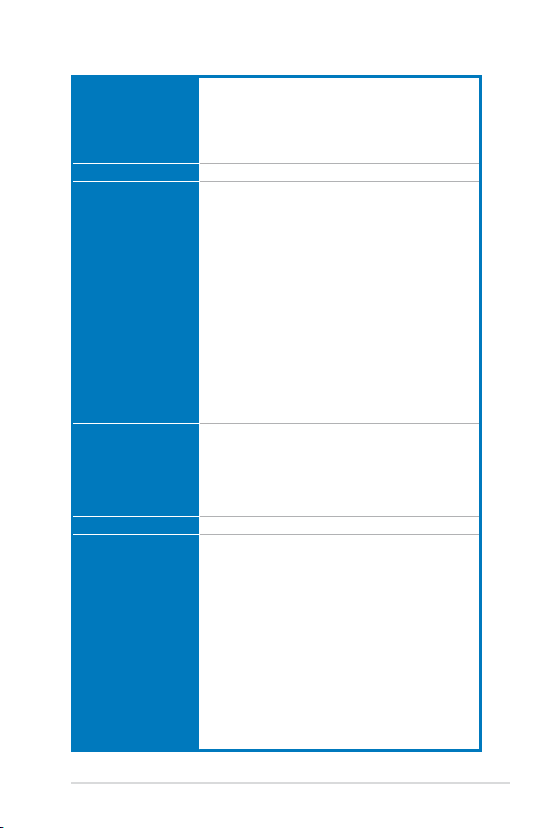
RAMPAGE IV BLACK EDITION specications summary
Intel® Core™ i7 Processors for LGA 2011 socket
Support 22nm CPU
CPU
Chipset Intel® X79 Express Chipset
Memory
Expansion Slots
Multi-GPU Technology
Storage
LAN Intel® Gigabit Ethernet LAN
SupremeFX
High Denition Audio
Intel® Turbo Boost Technology 2.0
* Refer to www.asus.com for Intel CPU support list.
** The Intel® Turbo Boost Technology 2.0 support depends on the CPU
types.
8 x DIMM, max. 64GB, DDR3 2800(O.C.)/2666(O.C.)/
2400(O.C.)/2133(O.C.)/1866/1600/1333/1066 MHz, non-ECC,
un-buffered memory
Supports Intel® Extreme Memory Prole (XMP)
* Hyper DIMM support is subject to the physical characteristics of
individual CPUs.
** Due to CPU behavior, DDR3 2200/2000/1800 MHz memory module will
run at DDR3 2133/1866/1600 MHz frequency as default.
*** Please refer to Memory QVL (Qualied Vendors List) for details.
4 x PCIe3.0 x16 slots, support x16; x16/x16; x16/x8/x16 and
x16/x8/x8/x8 congurations
2 x PCIe2.0 x1 slots
* This motherboard is ready to support PCIe 3.0 SPEC. Functions will be
available when using PCIe 3.0-compliant devices. Please refer to
www.asus.com for updated details.
4-Way/ 3-Way/ Quad-GPU NVIDIA® SLI™ Technology
AMD CrossFireX™ Technology
Intel® X79 Express Chipset:
- 2 x SATA 6.0 Gb/s ports (gray)
- 4 x SATA 3.0 Gb/s ports (black)
®
- Intel
Rapid Storage Technology supports RAID 0, 1, 5, and 10
ASMedia® SATA 6.0 Gb/s controller:
- 2 x External SATA 6.0 Gb/s ports
- 4 x SATA 6.0 Gb/s ports (gray)
ROG SupremeFX Black 8-Channel High Denition
Audio CODEC
- SupremeFX Shielding Technology: Red Line PCB shielding,
PCB dedicated audio layer and EMI protection cover
- Cirrus Logic® CS4398 DAC: 120dB SNR, -107dB THD+N
(Max. 192kHz/ 24-bit)
- Texas Instruments® TPA6120A2 600ohm headphone amplier
- WIMA® lm capacitors
- ELNA® premium audio capacitors
- NEC TOKIN UC2 audio relay
- High-delity audio operational ampliers (OP-AMPs)
- Differential circuit design
- Content protection for full bitrate lossless DVD Audio, Blu-ray
DVD, and HD-DVD audio content playback
- Jack-detection and multi-streaming
- Optical S/PDIF out port at back panel
- Sonic Radar
- DTS Connect
(continued on the next page)
ix
Page 10

Wireless
USB
ROG Exclusive Features
Wi-Fi 802.11 a/b/g/n/ac supports dual band frequency 2.4/5 GHz
Bluetooth V4.0
Intel® X79 Chipset:
- 10 x USB 2.0/1.1 ports (6 ports at mid-board*, 3 ports at back
panel, 1 port reserved for ROG Connect)
* 2 x USB2.0 ports at mid-board shares with ROG extension
(ROG_EXT) port.
ASMedia® USB 3.0 SuperSpeed USB HUB Controller:
- 8 x USB 3.0/2.0 ports (6 at back panel, 2 at mid-board)
ROG Extreme OC kit
- Slow Mode
- LN2 Mode
- PCIe x16 Lane switch
- EZ Plug
ROG Connect
- RC Poster
- RC Remote
- RC Diagram
ROG Extreme Engine Digi+ III
- 8 phase CPU power
- 3 phase VCCSA power
- 2+2 phase DRAM power
- NexFET™ Power Block MOSFET
- 60A chokes
- 10K Black Metallic Capacitors
UEFI BIOS features
- ROG BIOS Print
- GPU.DIMM Post
- Extreme Tweaker
- Tweakers’ Paradise (CPU/Memory/PCH)
- ROG SSD Secure Erase
- O.C. Prole
- ROG Pulse
CPU Level Up
ProbeIt
ROG RAMDisk
(continued on the next page)
x
Page 11

Special Features
Back Panel I/O Ports
ASUS Dual Intelligent Processors 4
- 4-Way Optimization Tuning Key, consolidating DIGI+ Power
Control, TPU, EPU, and Fan Xpert 2
ASUS Wi-Fi GO!
Overclocking Protection
- COP EX (Component Overheat Protection - EX)
- ASUS C.P.R.(CPU Parameter Recall)
ASUS Exclusive Features
- MemOK!
- Onboard Switches: Power/Reset/Clr CMOS (at rear)
- AI Suite 3
- USB 3.0 Boost
- USB Charger+
- AI Charger+
- Disk Unlocker
ASUS EZ DIY
- USB BIOS Flashback
- ASUS CrashFree BIOS 3
- ASUS EZ Flash 2
ASUS Q-Design
- ASUS Q-Code
- ASUS Q-Shield
- ASUS Q-LED (CPU, DRAM, VGA, Boot Device LED)
- ASUS Q-Slot
- ASUS Q-DIMM
- ASUS Q-Connector
1 x PS/2 keyboard/mouse combo port
1 x Clear CMOS button
1 x ROG Connect button
2 x External SATA 6.0 Gb/s ports
1 x LAN (RJ45) port
6 x USB 3.0/2.0 ports (blue)
4 x USB 2.0/1.1 ports (1 port also for ROG Connect)
1 x ASUS Wi-Fi GO! module (Wi-Fi 802.11 a/b/g/n/ac
and Bluetooth v4.0)
1 x Optical S/PDIF out
5 x Audio jacks
(continued on the next page)
xi
Page 12
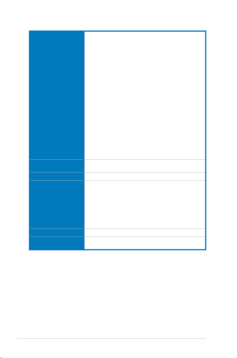
1 x USB 3.0 connectors supports additional 2 USB 3.0 ports
3 x USB 2.0 connectors supports additional 6 USB 2.0 ports
[one connector via ROG_EXT header]
6 x SATA 6.0 Gb/s connectors (gray)
4 x SATA 3.0 Gb/s connectors (black)
1 x ROG extension (ROG_EXT) header
8 x 4-pin Fan connectors: 2 x CPU / 3 x Chassis / 3 x Optional
11 x ProbeIt Measurement points
3 x Thermal sensor connectors
1 x SPDIF_Out header
1 x 24-pin EATX Power connector
Internal I/O Connectors
BIOS Features
Manageability WfM2.0, DMI2.7, WOL by PME, PXE
Software
Operating Systems Support Windows® 7, Windows® 8 , Windows® 8.1
Form Factor
1 x 8-pin ATX 12V Power connector
1 x 4-pin ATX 12V power connector
1 x LN2 Mode header
1 x Slow Mode switch
1 x START (Power On) button
1 x RESET button
1 x EZ Plug connector(s) (4-pin Molex power connector)
1 x MemOK! button
1 x BIOS Switch button
1 x Audio front panel (AAFP)
1 x System panel connector
1 x TPM connector
1 x DirectKey button
1 x DRCT (DirectKey) header
2 x 64Mb UEFI AMI BIOS, PnP, DMI2.7, WfM2.0, SM BIOS 2.7,
ACPI5.0a Multi-Language BIOS
Support DVD
- Drivers and Applications
- Daemon Tool Pro Standard
- Kaspersky Anti-Virus
- ROG CPU-Z
- ROG Mem TweakIt
- ROG RAMDisk
- ASUS Utilities
- ASUS WebStorage
Extended ATX Form Factor, 12-inch x 10.7-inch
(30.5cm x 27.2 cm)
*Specications are subject to change without notice.
xii
Page 13

OC Panel specications summary
Display 2.6-inch LCM
Pure hardware-based overclocking support
Boot debug POST code
Intuitive tuning in two OC modes
- EXTREME Mode for subzero OC benching
- NORMAL Mode for in-chassis usage
Seamless integration with CPU Level Up at one-click OC button
Real-time control and display CPU fan speed, temperature, BCLK
and RATIO
Adjustable system voltages, frequencies on-the-y
Stylish design with 90 plus-degree-tilt movable faceplate
Features
I/O Ports
Power
Installation
Requirements
Compatibility
(EXTREME Mode)
FanSpeed Control button
- Standard/Silent/Turbo mode
Four (4) additional 4-pin fan headers
LCM backlight on/off
ROG exclusive features
- VGA Hotwire
- Subzero Sense
- Slow Mode
- Pause Switch
- VGA SMB header
- ProbeIt
POWER : 1 x SATA power connector
ROG_EXT port : 1 x 18-1 pin data connection port
FAN : 4 x 4-pin extra Fan connectors
Voltage : +12V, +5V, +5VSB
Power consumption : 5A
1 x 5.25-inch drive bay required for NORMAL Mode installation
1 x SATA power cable from system power supply
RAMPAGE IV BLACK EDITION and other motherboards with
ROG_EXT port
*Visit the ASUS website at www.asus.com for the latest motherboard
support/compatibility lists.
**Please install the latest utility/rmware (ROG Connect Plus) for better
compatibility.
***Update the motherboard BIOS to the latest version for better
compatibility with OC Panel.
xiii
Page 14

Package contents
Check your motherboard package for the following items.
Motherboard ROG RAMPAGE IV BLACK EDITION
1 x ROG Connect cable
2 x 2-in-1 SATA 3.0 Gb/s signal cables
Cables
Accessories
Application DVD
Documentation
3 x 2-in-1 SATA 6.0 Gb/s signal cables
1 x SLI® cable
1 x CrossFireTM cable
1 x I/O Shield
OC Panel Kit
- 1 x OC Panel
- 1 x OC Panel 5.25-inch drive bay metal case
- 1 x OC Panel cable
- 1 x set of screws
1 x 2T2R dual-band Wi-Fi moving antennas
1 x ROG Magnet
1 x 2-in-1 ASUS Q-Connector Kit
1 x 12-in-1 ROG Cable label
1 x X-Socket pad
1 x 4-WAY SLI® bridge
1 x 3-WAY SLI® bridge
ROG motherboard support DVD
User’s manual
xiv
If any of the above items is damaged or missing, contact your retailer.
Page 15
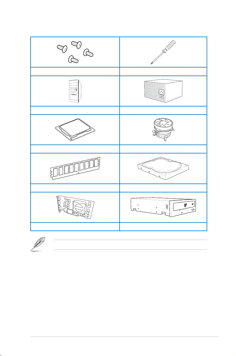
Installation tools and components
1 set of screws Philips (cross) screwdriver
PC chassis Power supply unit
Intel LGA 2011 CPU Intel LGA 2011 compatible CPU Fan
DDR3 DIMM SATA hard disk drive
Graphics card SATA optical disc drive (optional)
The tools and components in the table above are not included in the motherboard package.
xv
Page 16

xvi
Page 17

Chapter 1: Product Introduction
Product introduction
1
1.1 Special features
1.1.1 Product highlights
LGA2011 socket for Intel® Core™ i7 processor family
This motherboard supports Intel® Core™ i7 processor family in the LGA2011 package and
supports both the Sandy Bridge-E and the Ivy Bridge-E processors. It provides great system
performance with its quad-channel DDR3 memory slots, PCI Express 2.0/3.0 expansion
slots, and level 3 (L3) cache sizes.
Intel® X79 Express Chipset
Intel® X79 Express Chipset is a single chipset that supports the LGA2011 socket for the
Intel® Core™ i7 processor family. It utilizes the serial point-to-point links, which increases
bandwidth and enhances the system’s performance.
PCIe 3.0 Ready
The PCI Express bus standard delivers improved encoding for twice the performance of
current PCIe 2.0. Total bandwidth for a x16 link reaches a maximum of 32Gb/s, double the
16Gb/s of PCIe 2.0 in x16 mode. PCIe 3.0 provides you unprecedented data speeds, with the
convenience and seamless transition offered by complete backward compatibility with PCIe
1.0 and PCIe 2.0 devices, and improves and optimizes graphics performance.
* This motherboard is ready to support PCIe 3.0 specication. Functions are available when using PCIe 3.0-
compliant devices. Refer to www.asus.com for updated details.
3-Way/4-way/Quad-GPU SLI™ and CrossFireX™ Support
This motherboard features the most powerful Intel® X79 platform that optimizes PCIe
allocation in multi-GPU SLI and CrossFireX™ solution, giving you a brand-new gaming
enjoyment.
Quad-Channel, 8 x DIMM DDR3 2800 (O.C.)/ 2666 (O.C)/ 2400 (O.C.)/
2133(O.C.)/ 1866 / 1600 / 1333 / 1066 MHz Support
The motherboard supports the quad-channel DDR3 memory that features data transfer rates
of DDR3 2800(O.C.)/ 2666(O.C.)/ 2400(O.C.)/ 2133(O.C.)/ 1866/ 1600/ 1333/ 1066 MHz
to boost the system’s performance, and to meet the higher bandwidth requirements of 3D
graphics, multimedia and Internet applications.
* Due to CPU behavior, DDR3 2200 / 2000 / 1800MHz memory modules run at DDR3 2133/1866/1600MHz
frequencies as default.
Extra SATA 6Gb/s support
The Intel® X79 Express Chipset natively supports the next-generation SATA (Serial ATA)
interface, delivering up to 6Gb/s data transfer. ASUS provides extra 6Gb/s ports with
enhanced scalability, faster data retrieval, and double the bandwidth of current bus systems.
Chapter 1
ASUS RAMPAGE IV BLACK EDITION
1-1
Page 18

8 DIMM Design
Support for up to 64GB of system memory with an 8-DIMM design on this motherboard
provides you to fully use of modern 64-bit software, ideal for rendering detailed images or
manipulating large les. It also allows you to set up big RAM disks and speed up frequently
accessed programs, minimizing the impact of storage transfer delays while maximizing user
benet.
Complete USB 3.0 integration
This motherboard offers you the strategic USB 3.0 accessibility for both the front and rear
panels, allowing you to experience the convenience of the latest plug and play connectivity
solution at speed up to ten times faster than USB 2.0.
1.1.2 ROG Unique Gaming Features
SupremeFX Black
SupremeFX Black delivers premium audio quality without a separate audio card. SupremeFX
Shielding Technology using physical PCB isolation, grounding separation, and EMI cover
shielding combined with premium components such as ELNA audio capacitors and Germanmade WIMA Film capacitors result in audiophile level audio performance. Lossless audio
quality is ensured thanks to a new front-panel headphone DAC that delivers up to 120dB
SNR. Enhanced with a 600 Ohm headphone amplier, every sound detail is boosted to
maximum clarity and audibility.
Sonic Radar
Sonic awareness can make or break online combat, so we’ve developed a stealthy overlay
that shows you what opponents and teammates are up to. Gunshots, footsteps, and call outs
appear with precise directioning on the on-screen radar, which gives you the advantage of
better intelligence and avoiding sneaky opponent surprises. Even snipers can’t get away that
easy! Plus, it integrates Enhancer, which has four pre-set equalizer bands optimized to FPS
games you can select to best-suit your gameplay preferences, leading to games that always
sound better, clearer, and more real.
GameFirst II
Offering powerful, yet easy-to-use network control, ROG GameFirst II with cFos Trafc
Shaping technology is revamped with a more intuitive ROG user interface. Featuring both
an exclusive EZ Mode for beginners to setup and Advanced Mode for professional users to
tweak, it means whatever your PC does in the background; your fragging will always come
rst!
Chapter 1
Intel Gigabit LAN
The LAN solution from Intel has been long known to have a better throughput, lower CPU
utilization as well as better stability. With the Intel Gigabit LAN solutions onboard, the
ultimate network experience can therefore be delivered to its users like never before.
1-2
Chapter 1: Product introduction
Page 19

1.1.3 ROG exclusive features
Extreme Engine Digi+ III
Extreme Engine Digi+ III offers you a hardcore power delivery for a challenging and extreme
gaming enjoyment. It utilizes the best components such as NexFET™ Power Block
MOSFETs, 60A chokes, and super-premium 10K black metallic solid state capacitors. The
NexFET™ Power Block MOSFETs combine great durability and up to 90% efciency under
normal operation. 60A chokes can handle as much as 60A of power, which is twice that of
generic chokes. Super-premium 10K Black Metallic solid state capacitors are forged for
overclocking and the most extreme demands, lasting up to ve times longer than generic
capacitors with 20% wider temperature tolerance.
iROG
The iROG is a special IC that fully maximizes ROG’s unique functions, providing you with full
control of your motherboard at any stage. It greatly increases your overclocking enjoyment,
and offers you with advanced system control and management features purely at a hardware
level.
RAMDisk
RAMDisk reserves part of system memory and turns it into actual storage, so you can
place favorite app and game cache les in it to enjoy high-speed RAM performance while
accessing them. Plus, this extends SSD lifespan and keeps your main storage optimized for
really important tasks, and you get auto data backup and restore.
NOTE: RAMDisk only supports 64-bit operating systems.
CPU Level Up
With ROG’s CPU Level Up, overclocking has never been so easy, or cost-free. Simply select
the processor that you want to overclock to, and the motherboard will do the rest.
ROG Connect
ROG Connect allows you to monitor the status of your desktop PC and tweak its parameters
in real-time via a notebook. ROG Connect links your main system to a notebook through a
USB cable, allowing you to view real-time POST code and hardware status readouts on your
notebook, as well as make on-the-y parameter adjustments at a purely hardware level.
ASUS RAMPAGE IV BLACK EDITION
Chapter 1
1-3
Page 20

GPU.DIMM Post
GPU.DIMM Post enables you to catch potential problems even before you enter the OS,
saving you valuable time in detecting component failure under extreme conditions. With GPU.
DIMM Post, quickly and easily check your graphic cards, memory modules’ statuses in the
BIOS, and overclocking settings.
BIOS Print
ROG offers a whole new UEFI BIOS feature to handle the demands of an overclocking
experience. The motherboard features ROG BIOS Print that allows you to easily share your
BIOS settings to others with the press of a button.
ProbeIt
This motherboard consists of eleven (11) ProbeIt measurement points that helps you detect
your system’s current voltage. With the use of a multimeter device, these points can help
measure your system’s important system voltages.
Extreme Tweaker
Extreme Tweaker is the one stop shop to ne-tune your system to optimal performance.
With Extreme Tweaker, you can adjust the system settings such as frequency, over-voltage,
memory timing, and more.
Loadline Calibration
Maintaining ample voltage support for the CPU is critical during overclocking. The
Loadline Calibration ensures stable and optimal CPU voltage under heavy loading. It helps
overclockers enjoy the motherboard's ultimate OC capabilities and benchmark scores.
OC Panel
Overclocking made easier than ever! No more messing with the BIOS, OS, or software
utilities. OC Panel is the next step in dedicated direct tweaking. It works inside the case or
as an external console, and features normal mode with info covering CPU temp, ratio, base
clock, and CPU fan speed. With one press of the CPU Level Up button you can instantly
apply custom proles designed by the world’s leading overclockers, while FanSpeed Control
modies blower RPMs. In extreme mode, some of the most commonly used voltage tuning
settings are offered, along with Subzero Sense and VGA Hotwire, giving you eld access to
super-cool liquid thermal temp readings and streamlined hardware-level GPU overvolting.
Chapter 1
1-4
Chapter 1: Product introduction
Page 21

1.1.4 ASUS special features
AI Suite 3
With its user-friendly interface, ASUS AI Suite 3 consolidates all the exclusive ASUS
features into one simple-to-use software package. It allows you to supervise fan speed
control, voltage and sensor readings. This all-in-one software offers diverse and ease to use
functions, with no need to switch back and forth between different utilities.
USB BIOS FlashBack
USB BIOS Flashback offers a hassle-free updating solution for your ultimate convenience.
Simply install a USB storage device containing the BIOS le, press the BIOS Flashback
button for three seconds, and the UEFI BIOS is automatically updated even without entering
the existing the BIOS or operating system. It also allows you to regularly check for UEFI
BIOS updates, and download the latest BIOS automatically.
Wi-Fi GO!
ASUS Wi-Fi GO! leads the way to a more enjoyable home entertainment. With ASUS Wi-Fi
GO!, you can wirelessly stream media les to HDTV devices, remotely control and access
your computer using your mobile device, and easily transfer les between your computer and
mobile device.
Conveniently use and enjoy these ASUS Wi-Fi GO! functions:
Cloud GO!: Allows you to control les and sync them all across cloud services in a few
•
clicks.
•
Media Streaming Hub: Allows you to stream media les to an HDTV device.
•
Remote Desktop: Allows you to view your computer’s desktop and remotely operate
•
your computer in real-time from your mobile device.
Remote Keyboard and Mouse: Allows you to use your mobile device’s touch panel as a
•
remote keyboard and mouse for your computer.
Smart Motion Control: Allows you to remotely control your computer using your mobile
•
device’s customized gestures.
File Transfer: Allows you to transfer les between your computer and mobile device.
•
Capture and Send: Allows you to take screenshots and send them to a mobile device.
•
ASUS RAMPAGE IV BLACK EDITION
Chapter 1
1-5
Page 22

1.1.5 ROG rich-bundled software
Kaspersky® Anti-Virus
Kaspersky® Anti-Virus Personal offers premium antivirus protection for individual users and
home ofces. It is based on advanced antivirus technologies. The product incorporates the
Kaspersky® Anti-Virus engine, which is renowned for malicious program detection rates that
are among the industry’s highest.
DAEMON Tools Pro Standard
DAEMON Tools Pro offers essential functionality to backup CD, DVD and Blu-ray discs. It
converts optical media into virtual discs and emulates devices to work with the virtual copies.
DAEMON Tools Pro organizes data, music, video, and photo collections on a PC, notebook,
or netbook.
ROG CPU-Z
ROG CPU-Z, authorized by Intel’s CPU Identication (CPUID), is a customized ROG utility
that allows you to gather information about your system’s main components. It gives you
the current information and status of your CPU, motherboard, memory, and other main
components. Get that ROG look of reporting your system’s current information with ROG
CPU-Z.
MemTweakIt
MemTweakIt is a DRAM efciency tool that allows you to ne-tune your DRAM in real time
and allows you to post and share your DRAM conguration scores to the ROG website.
DTS Connect
To get the most out of your audio entertainment across all formats and quality levels, DTS
Connect combines two enabling technologies, DTS Neo:PC™ upmixes stereo sources (CDs,
MP3s, WMAs, internet radio) into as many as 7.1 channels of incredible surround sound.
Consumers can connect their PC to a home theater system. DTS Interactive is capable of
performing mult-channel encoding of DTS bitstreams on personal computers, and sending
encoded bitstreams out of a digital audio connection (such as S/PDIF or HDMI) designed to
deliver audio to an external decoder.
Chapter 1
1-6
Chapter 1: Product introduction
Page 23

1.2 Motherboard overview
1.2.1 Before you proceed
Take note of the following precautions before you install motherboard components or change
any motherboard settings.
• Unplug the power cord from the wall socket before touching any component.
• Before handling components, use a grounded wrist strap or touch a safely grounded
object or a metal object, such as the power supply case, to avoid damaging them due
to static electricity.
• Hold components by the edges to avoid touching the ICs on them.
• Whenever you uninstall any component, place it on a grounded antistatic pad or in the
bag that came with the component.
• Before you install or remove any component, ensure that the ATX power supply is
switched off or the power cord is detached from the power supply. Failure to do so
may cause severe damage to the motherboard, peripherals, or components.
ASUS RAMPAGE IV BLACK EDITION
Chapter 1
1-7
Page 24
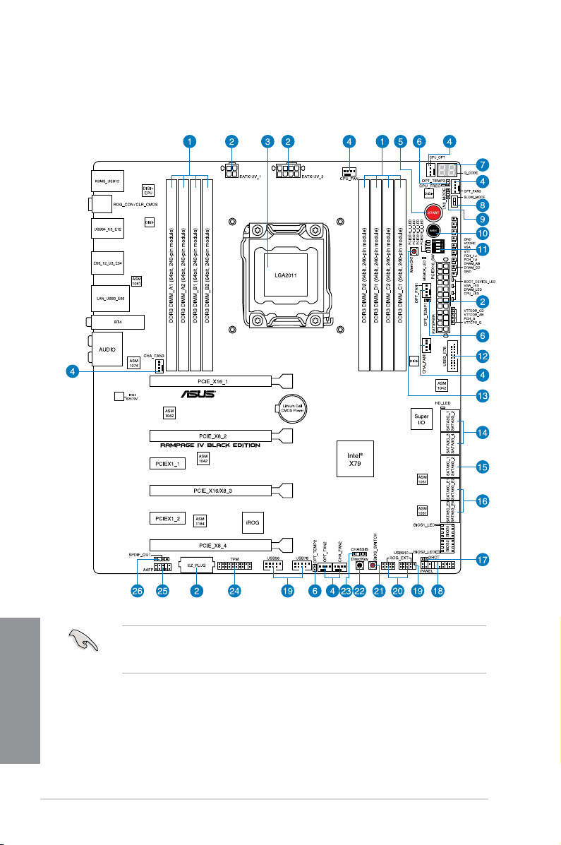
1.2.2 Motherboard layout
Chapter 1
1-8
Refer to section 1.2.9 Internal connectors and the section about the Rear I/O Connection
on Chapter 2 for more information about the internal connectors and rear panel
connectors.
Chapter 1: Product introduction
Page 25
Layout contents
Connectors/Jumpers/Slots Page
1. DDR3 DIMM slots channel 1-11
ATX power connectors (24-pin EATXPWR; 4-pin EATX12V_1;
2.
3.
4.
4-pin CPU_OPT; 4-pin CHA_FAN1/ CHA_FAN2/ CHA_FAN3;
4-pin OPT_FAN1/ OPT_FAN2 / OPT_FAN3)
5.
6.
OPT_TEMP2; OPT_TEMP3)
7. Q-Code LEDs
8.
9.
10.
11.
12.
13.
14.
SATA3G_2; SATA3G_3; SATA3G_4 [black])
15.
(7-pin SATA6G_1; SATA6G_2 [gray])
16.
SATA6G_E2; SATA6G_E3 ; SATA6G_E4 [gray])
17.
18.
19.
20.
21.
22.
23.
24.
25.
26.
8-pin EATX12V_2)
LGA2011 CPU socket 1-10
CPU, chassis, and power fan connectors (4-pin CPU_FAN;
Power-on (START) button 1-24
Thermal sensor cable connectors (2-pin OPT_TEMP1;
Slow Mode Switch 1-28
LN2 Mode jumper (3-pin LN2) 1-38
Reset button 1-24
PCIe x16 Lane switch 1-27
USB 3.0 connector (20-1 pin USB3_78) 1-42
MemOK! button 1-25
Intel® X79 Serial ATA 3.0 Gb/s connectors (7-pin SATA3G_1;
Intel® X79 Serial ATA 6.0 Gb/s connectors
ASMedia® Serial ATA 6.0 Gb/s connectors (7-pin SATA6G_E1;
DirectKey connector (2-pin DRCT) 1-47
System panel connector (20-8 pin PANEL) 1-50
USB 2.0 connectors (10-1 pin USB56; USB78; USB910) 1-43
ROG Extension - ROG_EXT connector (18-1 pin ROG_EXT) 1-47
BIOS Switch button 1-27
DirectKey button 1-26
Chassis intrusion connector (4-1 pin CHASSIS) 1-48
TPM connector (20-1 pin TPM) 1-48
Front panel audio connector (10-1 pin AAFP) 1-46
Digital audio connector (4-1 pin SPDIF_OUT) 1-44
1-49
1-45
1-42
1-31
1-40
1-39
1-41
ASUS RAMPAGE IV BLACK EDITION
Chapter 1
1-9
Page 26
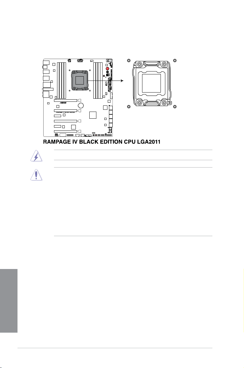
1.2.3 Central Processing Unit (CPU)
The motherboard comes with a surface mount LGA2011 socket designed for Intel® Core™ i7
Processor Family for the LGA 2011 socket.
Ensure that all power cables are unplugged before installing the CPU.
• Upon purchase of the motherboard, ensure that the PnP cap is on the socket and
the socket contacts are not bent. Contact your retailer immediately if the PnP cap
is missing, or if you see any damage to the PnP cap/socket contacts/motherboard
components. ASUS will shoulder the cost of repair only if the damage is shipment/
transit-related.
• Keep the cap after installing the motherboard. ASUS will process Return Merchandise
Authorization (RMA) requests only if the motherboard comes with the cap on the
LGA2011 socket.
• The product warranty does not cover damage to the socket contacts resulting from
incorrect CPU installation/removal, or misplacement/loss/incorrect removal of the PnP
cap.
Chapter 1
1-10
Chapter 1: Product introduction
Page 27
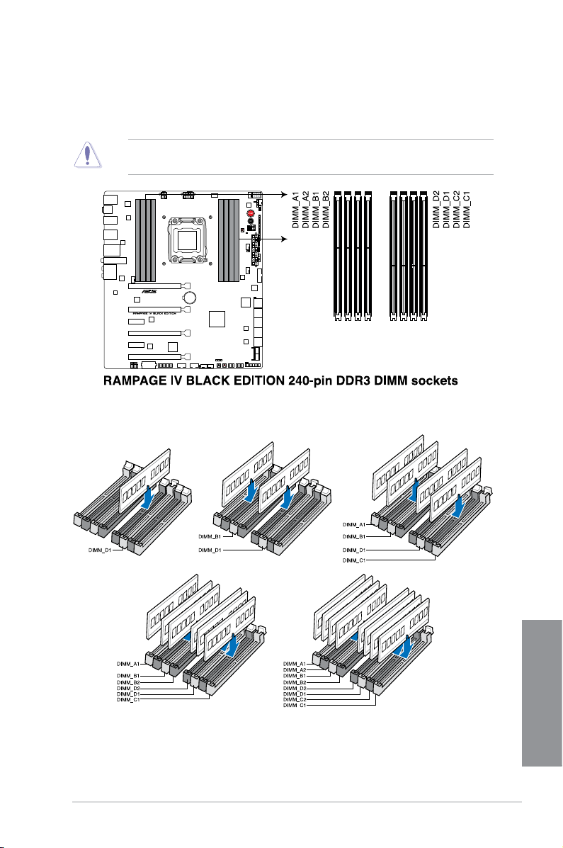
1.2.4 System memory
The motherboard comes with four Double Data Rate 3 (DDR3) Dual Inline Memory Modules
(DIMM) slots.
A DDR3 module is notched differently from a DDR or DDR2 module. DO NOT install a DDR
or DDR2 memory module to the DDR3 slot.
Recommended memory congurations
ASUS RAMPAGE IV BLACK EDITION
Chapter 1
1-11
Page 28

Memory congurations
You may install 2GB, 4GB and 8GB unbuffered and non-ECC DDR3 DIMMs into the DIMM
sockets.
Chapter 1
• You may install varying memory sizes in Channel A, Channel B, Channel C, and
Channel D. The system maps the total size of the lower-sized channel for the dualchannel conguration. Any excess memory from the higher-sized channel is then
mapped for single-channel operation.
• According to Intel
®
CPU spec, DIMM voltage below 1.65V is recommended to protect
the CPU.
• Due to CPU behavior, DDR3 2200/2000/1800 MHz memory modules run at DDR3
2133/1866/1600 MHz frequency as default.
• Always install DIMMs with the same CAS latency. For optimum compatibility, we
recommend that you obtain memory modules from the same vendor.
• Due to the memory address limitation on 32-bit Windows
®
OS, when you install 4GB
or more memory on the motherboard, the actual usable memory for the OS can be
about 3GB or less. For effective use of memory, we recommend that you do any of the
following:
a) Use a maximum of 3GB system memory if you are using a 32-bit Windows
b) Install a 64-bit Windows
®
OS when you want to install 4GB or more on the
®
OS.
motherboard.
c) For more details, refer to the Microsoft
®
support site at http://support.microsoft.
com/kb/929605/en-us.
• This motherboard does not support DIMMs made up of 512Mb (64MB) chips or less
(Memory chip capacity counts in Megabit, 8 Megabit/Mb = 1 Megabyte/MB).
• The default memory operation frequency is dependent on its Serial Presence Detect
(SPD), which is the standard way of accessing information from a memory module.
Under the default state, some memory modules for overclocking may operate at a
lower frequency than the vendor-marked value. To operate at the vendor-marked or at
a higher frequency, refer to section 3.4 Extreme Tweaker menu for manual memory
frequency adjustment.
• For system stability, use a more efcient memory cooling system to support a full
memory load (8 DIMMs) or overclocking condition.
• Memory modules with memory frequency higher than 2133MHz and their
corresponding timing or the loaded XMP prole is not the JEDEC memory standard.
The stability and compatibility of the memory modules depend on the CPU’s
capabilities and other installed devices.
• Always install the DIMMS with the same CAS Latency. For an optimum compatibility,
we recommend that you install memory modules of the same version or data code (D/
C) from the same vendor. Check with the vendor to get the correct memory modules.
1-12
Chapter 1: Product introduction
Page 29
RAMPAGE IV BLACK EDITION Motherboard Qualied Vendors List (QVL)
DDR3 2800 MHz capacity
Vendors Part No. Size
CORSAIR CMD16GX3M4A2800C12 16GB (4x4GB) DS - - 12-14-14-36 1.65 •
CORSAIR CMD16GX3M4A2800C11 16GB (4x4GB) DS - - 11-14-14-35 1.65 •
G.SKILL F3-2800C12Q-32GTXDG 32GB (4x8GB) DS - - 12-14-14-35 1.65 •
G.SKILL F3-2800C11Q-16GTXDG 16GB (4x4GB) DS - - 11-14-14-35 1.65 •
ADATA AX3U2800GW8G12-DG2 32GB (4x8GB) DS - - 12-14-14-36 1.65 •
ADATA AX3U2800GW4G12-DG2 16GB (4x4GB) SS - - 12-14-14-36 1.65 •
AVEXIR AVD3U28001204G-4CI 16GB (4x4GB) DS - - 12-14-14-35 1.65 •
SS/DSChip
Brand
Chip
NO.
Timing Voltage
DDR3 2666 MHz capacity
Vendors Part No. Size
CORSAIR CMD16GX3M4A2666C10 16GB (4x4GB) DS - - 10-12-12-31 1.65 •
G.SKILL F3-2666C10Q-16GTXD 16GB (4x4GB) DS - - 10-12-12-31 1.65 •
Team TXD38G2666HC11CBK 32GB (4x8GB) DS - - 11-13-13-35 1.65 •
SS/DSChip
Brand
Chip
NO.
Timing Voltage
DDR3 2400 MHz capacity
Vendors Part No. Size
A-DATA AX3U2400GW8G11(XMP) 16GB
Apacer 78.BAGFL.AFD0C(XMP) 8GB (2x4GB) DS - - 11-12-12-30 - • •
Apacer 783BAGF3.AFD0C(XMP) 8GB (2x4GB) DS - - 11-11-11-30 - • •
CORSAIR CMD16GX3M2A2400C10
CORSAIR CMY16GX3M2A2400C10A
CORSAIR CMY16GX3M2A2400C10R
CORSAIR CMZ16GX3M2A2400C10
G.SKILL F3-19200CL10Q2-
G.SKILL F3-2400C11Q-32GXM
G.SKILL F3-19200CL10Q-
(Ver4.21)(XMP)
(Ver4.21)(XMP)
(Ver4.21)(XMP)
(Ver4.21)
64GBZHD
(XMP)
(XMP)
32GBZHD
(XMP)
(2x8GB)
16GB
(2x8GB)
16GB
(8x2GB)
16GB
(2x8GB)
16GB
(2x8GB)
64GB
(8x8GB)
32GB
(4x8GB)
32GB
(4x8GB)
SS/DSChip
DS - - 11-13-13-35 1.65 • •
DS - - 10-12-12-31 1.65 • •
DS - - 10-12-12-31 1.65 • •
DS - - 10-12-12-31 1.65 • •
DS - - 10-12-12-31 1.65 • • •
DS - - 10-12-12-31 1.65 • • •
DS - - 11-13-13-31 1.65 • • •
DS - - 10-12-12-31 1.65 •
Brand
Chip
NO.
Timing Voltage
DIMM socket support
(Optional)
2 4 6 8
DIMM socket support
(Optional)
2 4 6 8
DIMM socket support
(Optional)
2 4 6 8
Chapter 1
(Continued on the next page)
ASUS RAMPAGE IV BLACK EDITION
1-13
Page 30

DDR3 2400 MHz capacity
Vendors Part No. Size
G.SKILL F3-19200CL11Q-
G.SKILL F3-19200CL9D-4GBPIS
G.SKILL F3-19200CL9Q-16GBZMD
GEIL GET34GB2400C9DC
GEIL GOC316GB2400C10QC
GEIL GOC316GB2400C11QC
KINGSTON KHX2400C11D3K4/8GX
KINGSTON KHX24C11K4/16X
KINGSTON KHX24C11T2K2/8X
KINGSTON KHX24C11T3K4
KINGSTON KHX24C11T3K4/32X
Mushkin 997122R
Silicon
Power
Team TXD34G2400HC10QBK
Transcend TX2400KLN-8GK
16GBZHD
(XMP)
(XMP)
(XMP)
(XMP)
(XMP)
(XMP)
(XMP)
(XMP)
(XMP)
(XMP)
(XMP)
(XMP)
SP004GXLYU240NSA
(XMP)
(XMP)
(XMP)
16GB
(4x4GB)
4G (2x2G ) DS - - 9-11-9-28 1.65 •
16GB
(4x4GB)
4GB (2x2GB) DS - - 9-11-9-27 1.65 •
16GB
(4x4GB)
16GB
(4x4GB)
8GB (4x2GB) SS - - 11-13-11-30 1.65 • •
16GB
(4x4GB)
8GB (2x4GB) DS - - - 1.65 • •
16GB
(4x4GB)
32GB
(4x8GB)
16GB
(2x8GB)
4GB SS - - 2400-11-13-
8GB (2x4GB) DS - - 10-12-12-31 1.65 • •
8GB
(2x4GB )
SS/DSChip
DS - - 11-11-11-31 1.65 •
DS - - 9-11-11-31 1.65 • •
DS - - 10-11-11-30 1.65 • •
DS - - 11-11-11-30 1.65 • •
DS - - 11-13-13-30 1.65 •
DS - - 2400-11-13-
DS - - 9-9-9-24 1.65 • •
DS - - 2400-10-12-
DS - - 2400-11-12-
Brand
Chip
NO.
Timing Voltage
13-30
12-28
13-32
11-29
DIMM socket support
2 4 6 8
1.65 • •
1.65 • •
- • •
1.6 • • •
(Optional)
Chapter 1
1-14
Chapter 1: Product introduction
Page 31

DDR3 2133 MHz capacity
Vendors Part No. Size SS/DS
Apacer 78.BAGE4.AFD0C(XMP)
Apacer AHU04GFB33CAQ3R(XMP) 4GB DS - -
CORSAIR
CORSAIR
CORSAIR
CORSAIR
CORSAIR
G.SKILL
G.SKILL
G.SKILL
G.SKILL F3-2133C10Q-32GSR(XMP)
G.SKILL F3-2133C11Q-32GZL(XMP)
KINGSTON
KINGSTON KHX21C11T3FK8/64X(XMP)
Team TLD34G2133HC11ABK(XMP)
Team TLD38G2133HC11ABK(XMP)
CMD16GX3M2A2133C9
(Ver4.21)(XMP)
CMD32GX3M4A2133C9
(Ver4.21)(XMP)
CMD8GX3M2A2133C9
(Ver1.5)(XMP)
CMD8GX3M2B2133C9
(Ver5.12)(XMP)
CMZ8GX3M2A2133C11R
(Ver4.21)(XMP)
F3-17000CL11Q264GBZLD(XMP)
F3-17000CL9Q16GBXLD(XMP)
F3-17000CL9Q16GBZH(XMP)
KHX2133C11D3K4/
16GX(XMP)
8GB
(2x4GB)
16GB
(2x8GB)
32GB
(4x8GB)
8GB
(2x4GB)
8GB
(2x4GB)
8GB
(2x4GB)
64GB
(8x8GB)
16GB
(4x4GB)
16GB
(4x4GB)
32GB
(4x8GB)
32GB
(4x8GB)
16GB
(4x4GB)
64GB
(8x8GB)
8GB
(2x4GB)
16GB
(2x8GB)
Chip
Brand
DS - - 9-9-9-24 - •
DS - - 9-11-11-31 1.65 •
DS - - 9-11-11-31 1.65 •
DS - - 9-11-10-27 1.5 •
DS - - 9-11-11-31 1.65 •
DS - -
DS - -
DS - - 9-11-9-28 1.65 •
DS - - 9-11-10-28 1.65 •
DS - -
DS - -
DS - -
DS - - 9-9-9-24 1.5 •
DS - -
DS - -
Chip
Timing Voltage
NO.
11-1313-31
11-1111-27
11-1111-30
10-1212-31
11-1111-31
11-1211-30
11-1111-31
11-1111-31
DIMM socket support
(Optional)
2 4 6 8
- •
1.5 •
1.5 •
1.5 •
1.5 •
1.65 •
1.65 •
1.65 •
DDR3 2000 MHz capacity
Vendors Part No. Size
AEXEA AXA3ES4GK2000LG28V
(XMP)
Asint SLA302G08-ML2HB
(XMP)
GEIL GUP34GB2000C9DC
(XMP)
ASUS RAMPAGE IV BLACK EDITION
SS/DSChip
4GB
DS - - - 1.65 • •
(2x2GB)
4GB DS Hynix H5TQ2G83BFRH9C 9-9-9-27 - • •
4GB
DS - - 9-9-9-28 1.65 • •
(2x2GB)
Brand
Chip NO. Timing Voltage
DIMM socket
support (Optional)
2 4 6 8
Chapter 1
1-15
Page 32

DDR3 1866 MHz capacity
Vendors Part No. Size
A-DATA AX3U1866XW8G10(XMP)
CORSAIR
CORSAIR
CORSAIR
CORSAIR
CORSAIR
CORSAIR
CORSAIR
CORSAIR
CORSAIR
CORSAIR
Crucial
Crucial
G.SKILL
G.SKILL
G.SKILL
G.SKILL
G.SKILL
G.SKILL
G.SKILL
Chapter 1
G.SKILL
KINGSTON
Team TED34GM1866C13BK 4GB DS Hynix H5TC2G83EFR 13-13-13-32 1.5 • •
Team TED38GM1866C13BK 8GB DS Hynix H5TQ4G83AFR 13-13-13-32 1.5 • •
Team
Team
CMD16GX3M4A1866C9
(Ver4.13)(XMP)
CMD16GX3M4A1866C9
(Ver8.16)(XMP)
CMD32GX3M4A1866C9
(Ver3.24)(XMP)
CMD8GX3M2A1866C9
(Ver4.13)(XMP)
CMT32GX3M4X1866C9
(Ver3.23)(XMP)
CMY16GX3M2A1866C9
(Ver 4.21)(XMP)
CMY8GX3M2A1866C9
(Ver3.24)(XMP)
CMZ16GX3M2A1866C10
(Ver5.29)(XMP)
CMZ32GX3M4X1866C10
(Ver3.23)(XMP)
CMZ8GX3M2A1866C9G
(Ver5.12)(XMP)
BLE8G3D1869DE1TX0.1
6FED(XMP)
BLE4G3D1869DE1XT0.1
6FMD(XMP)
F3-14900CL10Q2-
64GBZLD(XMP)
F3-14900CL10Q-
32GBZL(XMP)
F3-14900CL9D-
8GBSR(XMP)
F3-14900CL9Q-
16GBXL(XMP)
F3-14900CL9Q-
16GBZL(XMP)
F3-14900CL9Q-
16GBZL(XMP)
F3-14900CL9Q-
8GBFLD(XMP)
F3-1866C9Q-32GXM
(XMP)
KHX1866C9D3K2/8GX
(XMP)
TLD34G1866HC9KBK
(XMP)
TLD38G1866HC10SBK
(XMP)
SS/DSChip
16GB
DS - - 10-11-10-30 1.5 •
(2x8GB)
16GB
DS - - 9-10-9-27 1.5 •
(4x4GB)
16GB
DS - - 9-10-9-27 1.5 • •
(4x4GB)
32GB
DS - - 9-10-9-27 1.5 • •
(4x8GB)
8GB
DS - - - 1.5 •
(2x4GB)
32GB
DS - - 9-10-9-27 1.5 •
(4x8GB)
16GB
DS - - 9-10-9-27 1.5 • •
(2x8GB)
8GB
DS - - 9-10-9-27 1.5 •
(2x4GB)
16GB
DS - - 10-11-10-30 1.5 •
(2x8GB)
32GB
DS - - 10-11-10-27 1.5 •
(4x8GB)
8GB
DS - -
(2x4GB)
16GB
DS - -
(2x8GB)
4GB DS - - 9-9-9-27 1.5 •
64GB
DS - - 10-11-10-30 1.5 •
(8x8GB)
32GB
DS - - 10-11-10-30 1.5 •
(4x8GB)
8GB
DS - - 9-10-9-28 1.5 •
(2x4GB)
16GB
DS - - 9-10-9-28 1.5 •
(4x4GB)
16GB
DS - - 9-10-9-28 1.5 • •
(4x4GB)
16GB
DS - - 9-10-9-28 1.5 •
(4x4GB)
8GB
DS - - 9-9-9-24 1.6 •
(2xGB)
32GB
DS - - 9-10-9-28 1.5 • •
(4xGB)
8GB
DS - - - 1.65 • •
(2xGB)
8GB
DS - - 9-11-9-27 1.5 • •
(2xGB)
16GB
DS - - 10-11-10-30 1.5 •
(2x8GB)
Chip NO. Timing Voltage
Brand
1866 9-10-
9-27
1866-9-9-
9-27
1.5 • •
1.5 •
DIMM socket
support
(Optional)
2 4 6 8
1-16
Chapter 1: Product introduction
Page 33

DDR3 1600 MHz capacity
DIMM socket
Vendors Part No. Size
A-DATA AD3U1600W4G11 4GB SS A-DATA 3WCD-1211A
A-DATA AD3U1600W8G11 8GB DS A-DATA 3WCD-1211A
A-DATA AX3U1600W8G11
AMD AE32G1609U1-U 2GB SS AMD 23EY4587MB6H - 1.5 •
AMD AE34G1609U2-U 4GB DS AMD 23EY4587MB6H - 1.5 •
AMD AP38G1608U2K(XMP)
Apacer 78.B1GE3.9L10C 4GB DS Apacer AM5D5908DEQSCK - 1.65 •
Apacer 78.B1GET.9K00C 4GB SS Apacer AM5D6008BQQSCK
AHU04GFA60C9Q3R
Apacer
(XMP)
AHU08GFA60CBT3R
Apacer
(XMP)
SLA302G08-
Asint
EGG1C(XMP)
SLA302G08-EGJ1C
Asint
(XMP)
Asint SLA302G08-EGN1C 4GB DS ASint 302G08-GN1C - - •
Asint SLA304G08-ENG1B 4GB SS Asint 304G08-GN1B
SLB304G08-EGJ1B
Asint
(XMP)
Asint SLB304G08-EGN1B 8GB DS ASint 304G08-GN1B - - • •
Asint SLZ302G08-EGN1C 2GB SS ASint 302G08-GN1C - - •
AVD3U16000904G-
AVEXIR
2CW(XMP)
CMD8GX3M2A1600C8
CORSAIR
(Ver5.12)(XMP)
CMD8GX3M2A1600C9
CORSAIR
(Ver2.12)(XMP)
CML16GX3M2A1600C10
CORSAIR
(Ver2.21)(XMP)
CML8GX3M2A1600C9
CORSAIR
(Ver7.12)(XMP)
CORSAIR CMV8GX3M1A1600C11 8GB DS - -
CMX8GX3M2A1600C9
CORSAIR
(Ver3.19)(XMP)
CMZ16GX3M2A1600C10
CORSAIR
(Ver.3.24)(XMP)
SS/DSChip
16GB
DS - - 9-11-9-27 1.5 • •
(2x8GB)
8GB
DS - - 9-9-9-28 1.65 •
(2x4GB)
4GB DS - -
8GB DS - - 9-9-9-24 - •
4GB DS Asint 302G08-GG1C 9-9-9-27 - •
4GB DS Asint 302G08-GJ1C 9-9-9-27 - •
8GB DS - - 9-9-9-27 - •
8GB
DS - -
(2x4GB)
8GB
DS - -
(2x4GB)
8GB
DS - - 9-9-9-24 1.5 •
(2x4GB)
16GB
DS - -
(2x8GB)
8GB
DS - - 9-9-9- 24 1.5 •
(2x4GB)
8GB
SS - - 9-9-9-24 1.65 •
(2x4GB)
16GB
DS - -
(2x8GB)
Chip NO. Timing Voltage
Brand
11-1111-28
11-1111-28
11-1111-28
11-1111-28
9-1111-28
11-1111-28
1600 8-88-24
10-1010-27
11-1111-30
10-1010-27
(Continued on the next page)
support
(Optional)
2 4 6 8
- •
- •
- •
- •
- •
1.5 •
1.5 •
1.5 •
- •
1.5 •
Chapter 1
ASUS RAMPAGE IV BLACK EDITION
1-17
Page 34

DDR3 1600 MHz capacity
Vendors Part No. Size
CORSAIR
CORSAIR
CORSAIR
CORSAIR
Crucial
Crucial
Elixir
Elixir
G.SKILL
G.SKILL
G.SKILL
GEIL
KINGMAX
KINGMAX
KINGSTON
KINGSTON
KINGSTON
KINGSTON
KINGSTON
KINGSTON
Chapter 1
KINGSTON
KINGSTON KHX1600C9D3P1K2/8G
KINGSTON
CMZ16GX3M4A1600C9
(XMP)
CMZ16GX3M4X1600C9
(Ver8.16)(XMP)
CMZ32GX3M4X1600C10
(Ver2.2)(XMP)
CMZ8GX3M2A1600C8
(XMP)
BLS4G3D1609DS1S00.
16FMR(XMP)
BLT4G3D1608DT1TX0.
16FM(XMP)
M2X2G64CB88G7NDG(XMP)
M2X4G64CB8HG5NDG(XMP)
F3-12800CL9D8GBSR2(XMP)
F3-12800CL9Q16GBZL(XMP)
F3-1600C9Q-32GXM
(XMP)
GUP34GB1600C7DC
(XMP)
FLGE85F-C8KL9A
(XMP)
FLGF65F-C8KL9A
(XMP)
KHX16009CD3K2/8GX
(XMP)
KHX1600C9D3B1/4G
(XMP)
KHX1600C9D3K3/
12GX(XMP)
KHX1600C9D3K3/
6GX(XMP)
KHX1600C9D3K4/
16GX(XMP)
KHX1600C9D3K6/
24GX(XMP)
KHX1600C9D3LK2/
8GX(XMP)
KHX16C10B1K2/
16X(XMP)
SS/DSChip
16GB
DS - -
(4x4GB)
16GB
DS - -
(4x4GB)
32GB
DS - -
(4x8GB)
8GB
DS - -
(2x4GB)
4GB DS - -
4GB DS - -
2GB SS Elixir N2CB2G80GN-DG
4GB DS Elixir N2CB2G80GN-DG
8GB
DS - -
(2x4GB)
16GB
DS - -
(4x4GB)
32GB
DS - - - 1.5 • •
(4x8GB)
4GB
DS - -
(2x2GB)
2GB SS KINGMAX N/A
4GB DS KINGMAX N/A
8GB
DS - -
(2x4GB)
4GB SS - -
12GB
DS - - 9 1.65 •
(3x4GB)
6GB
DS - - 9 1.65 •
(3x2GB)
16GB
DS - -
(4x4GB)
24GB
DS - - 9 1.65 •
(6x4GB)
8GB
DS - -
(2x4GB)
8GB
DS - - 9 1.5 •
(2x4GB)
16GB
DS - - - 1.5 •
(2x8GB)
Chip NO. Timing Voltage
Brand
9-9-924
1600-99-9-24
10-1010-27
8-8-824
1600-99-9-24
8-8-824
9-9-928
9-9-928
9-9-924
9-9-924
7-7-724
9-9-928
9-9-928
9-9-927
9-9-927
9-9-924
9-9-924
DIMM socket
support
(Optional)
2 4 6 8
1.5 •
1.5 • •
1.5 • •
1.5 •
1.5 •
1.5 •
- •
- • •
1.25 •
1.5 • •
1.6 •
- •
- •
1.65 •
1.65 •
1.65 • •
1.35 •
1-18
(Continued on the next page)
Chapter 1: Product introduction
Page 35

DDR3 1600 MHz capacity
DIMM socket
Vendors Part No. Size
KINGSTON KHX16C9K2/16
KINGSTON KHX16C9P1K2/16
KINGSTON KVR16N11/4 4GB DS KINGSTON D2568JPUCPGGBU
KINGSTON KVR16N11/4 4G DS Hynix H5TQ2G83CFRPBC - 1.5 •
Micron
Micron
Micron
Patriot PV316G160C9K(XMP)
Patriot PV316G160C9K(XMP)
SanMax SMD-4G28N1P-16KM 4GB SS ELPIDA J4208BBBG-GN-F 1600 - • •
SanMax SMD-4G68HP-16KZ 4GB DS Hynix H5TQ2G83BFRPBC - 1.5 • •
SanMax SMD-4G68NG-16KK 4GB DS ELPIDA J2108BDBG-GN-F - - • •
SanMax SMD-8G28NP-16KM 8GB DS ELPIDA J4208BBBG-GN-F 1600 - • •
Silicon
Power
Silicon
Power
Team TED34GM1600C11BK 4GB DS Hynix H5TC2G83EFR
Team TED38GM1600C11BK 8GB DS Hynix H5TQ4G83AFR
Team
Team
Team
Transcend TS1GLK64V6H(620945) 8GB DS SAMSUNG K4B4G0846B - - •
Transcend TS1GLK64W6H 8GB DS SAMSUNG K4B4G0846B
MT16JTF1G64AZ1G6E1
MT8JTF51264AZ1G6E1
MT8KTF25664AZ1G6M1
SP002GBLTU160V02
(XMP)
SP004GBLTU160V02
(XMP)
TLD34G1600HC9BK
(XMP)
TLD38G1600HC9BK
(XMP)
TXD34096M1600HC9D(XMP)
SS/
Chip Brand Chip NO. Timing Voltage
DS
16GB
DS - -
(2x8GB)
16GB
DS - - - 1.5 •
(2x8GB)
8GB DS Micron D9QBJ - - • •
4GB SS Micron D9QBJ - - • •
2GB SS MICRON D9PFJ - - •
16GB
SS - -
(2x8GB)
16GB
SS - -
(2x8GB)
2GB SS S-POWER 20YT5NG
4GB DS S-POWER 20YT5NG
8GB
DS - -
(2x4GB)
16GB
DS - -
(2x8GB)
4GB DS Hynix H5TC2G83BFRH9A
13339-9-9-241.5 •
11-111128-1
16009-9-924
16009-9-924
9-1111-28
9-9-924
11-1111-28
11-1111-28
9-9-924
9-9-924
9-9-924
11-111128-1
support
(Optional)
2 4 6 8
- •
1.5 •
1.5 •
1.5 • •
1.5 •
1.5 • •
1.5 • •
1.5 • •
1.5 •
1.5 • •
- •
ASUS RAMPAGE IV BLACK EDITION
Chapter 1
1-19
Page 36

DDR3 1333 MHz capacity
Vendors Part No. Size
AMD AE32G1339U1-U 2GB SS AMD 23EY4587MB3H - 1.5 •
AMD AE34G1339U2-U 4GB DS AMD 23EY4587MB3H - 1.5 •
Apacer 78.B1GDE.9L10C 4GB DS Apacer AM5D5908CEHSBG 9 - • •
Asint SLA302G08-EDJ1C 2GB SS ASint 302G08-DJ1C - - •
Asint SLA304G08-EDJ1B 4GB SS Asint 304G08-DJ1B 9-10-
Asint SLB304G08-EDJ1B 8GB DS Asint 304G08-DJ1B 9-9-9-24- •
BUFFALO D3U1333-1G 1GB SS Elpida J1108BFBG-DJ-F - - •
BUFFALO D3U1333-2G 2GB DS Elpida J1108BFBG-DJ-F - •
BUFFALO D3U1333-4G 4GB DS NANYA NT5CB256M8BN-CG - •
CORSAIR CMV8GX3M1A1333C9 8GB DS - - 9-9-9-24- •
CORSAIR CMV8GX3M2A1333C9 8GB
CORSAIR CMX8GX3M2A1333C9
G.SKILL F3-10666CL9D-8GBXL 8GB
GEIL GVP34GB1333C9DC 4GB
INNODISK M3UN-2GHJBC09 2GB SS Hynix H5TQ2G83CFRH9C 9-9-9-24- • •
INNODISK M3UN-4GHJAC09 4GB DS Hynix H5TQ2G83CFRH9C 9-9-9-24- • •
KINGMAX FLFE85F-C8KL9 2GB SS KINGMAX KFC8FNLBF-
KINGMAX FLFE85F-C8KL9 2GB SS KINGMAX KFC8FNLXF-
KINGMAX FLFF65F-C8KL9 4GB DS KINGMAX KFC8FNLXF-
KINGSTON KVR1333D3E9S/4G 4GB DS Elpida J2108ECSE-DJ-F 9 1.5 •
KINGSTON KVR1333D3N9H/4G 4GB DS ELPIDA J2108BDBG-GN-F - 1.5 •
KINGSTON KVR13N9S8H/4 4GB SS ELPIDA J4208BBBG-GN-F - 1.5 •
Mach
Chapter 1
Xtreme
Mach
Xtreme
MICRON MT8JTF25664AZ-
Patriot PSD32G13332 2GB DS Prtriot PM128M8D3BU-15 9 - •
RiDATA C304627CB1AG22Fe 2GB DS RiDATA C304627CB1AG22Fe 9 - •
RiDATA E304459CB1AG32Cf 4GB DS RiDATA E304459CB1AG32Cf 9 - •
SS/
Chip Brand Chip NO. Timing Voltage
DS
DS - N/A 9-9-9-24- •
(2x4GB)
8GB
(XMP)
MXD3U133316GQ 16GB
MXD3V13332GS 2GB SS Mach
1G4M1
DS - - 9-9-9-241.5 •
(2x4GB)
DS - - 9-9-9-241.5 • •
(2x4GB)
DS - - 9-9-9-241.5 •
(2x2GB)
DS - - - - •
(4x4GB)
Xtreme
2GB SS MICRON D9PFJ - - • •
DIMM socket
support
(Optional)
2 4 6 8
- •
10-26
GXX-12A
DXX-15A
DXX-15A
C2S46D30-D313 - - • •
- - •
- - •
- - • •
1-20
(Continued on the next page)
Chapter 1: Product introduction
Page 37

DDR3 1333 MHz capacity
Vendors Part No. Size
Silicon
Power
Silicon
Power
Team TED34096M1333HC9 4GB DS Team T3D2568LT-13 - - •
Team TED34GM1333C9BK 4GB DS Hynix H5TQ2GB83CFR
Team TED38GM1333C9BK 8GB DS Hynix H5TQ4G83AFR
Transcend
SP001GBLTU133S02 1GB SS S-POWER 10YT3E5 9 - • •
SP004GBLTU133V02 4GB DS S-POWER 20YT3NG
JM1333KLH8G(623654)
Side(s): SS - Single-sided DS - Double-sided DIMM support:
Supports one (1) module inserted into any slot as Single-channel memory
conguration. We suggest that you install the module into D1 slot.
Supports two (2) modules inserted into one pair of the dark gray slots or the black
slots as one pair of dual-channel memory conguration. We suggest that you install
the modules into slots B1 and D1 for better compatibility.
Supports four (4) modules inserted into both the dark gray slots and black slots as two
pairs of quad-channel memory conguration. We suggest that you install the modules
into slots A1, B1, C1, and D1 for better compatibility.
Supports six (6) modules inserted into four dark gray slots and two black slots as three
pairs of quad-channel memory conguration. We suggest that you install the modules
into slots A1, B1, B2, C1, D1, and D2 for better compatibility.
Supports eight (8) modules inserted into all slots as fully-loaded quad-channel
memory congurations.
• ASUS exclusively provides hyper DIMM support function.
• Hyper DIMM support is subject to the physical characteristics of individual CPUs. Load
the X.M.P. or D.O.C.P. settings in the BIOS for the hyper DIMM support.
• Visit the ASUS website for the latest QVL.
SS/
Chip Brand Chip NO. Timing Voltage
DS
9-9-9-
- •
24
9-9-9-
1.5 • •
24
9-9-9-
1.5 • •
24
8GB DS Transcend TK963EBF3 - - •
DIMM socket
support
(Optional)
2 4 6 8
ASUS RAMPAGE IV BLACK EDITION
Chapter 1
1-21
Page 38

1.2.5 Expansion slots
Ensure to unplug the power cord before adding or removing expansion cards. Failure to do
so may cause you physical injury and damage motherboard components.
Slot No. Slot Description
1 PCIe 3.0 x16_1 slot
Chapter 1
1-22
2 PCIe 3.0 x8_2 slot
3 PCIe 2.0 x1_1 slot
4 PCIe 3.0 x16/8_3 slot
5 PCIe 2.0 x1_2 slot
6 PCIe 3.0 x8_4 slot
Chapter 1: Product introduction
Page 39

• Refer to the following conguration table for installation.
PCIe x16
Slot #
Single
VGA
SLI/CF
3 way
SLI/CFX
Quad
SLI/CFX
1 x16 x16 x16 x16
2 — — x8 x8
4 — x16 x16 x8
6 — — — x8
• We recommend that you provide sufcient power when running CrossFireX™ or SLI
mode.
• While running at heavy loaded four VGA cards, ensure to plug in the 6-pin extra PCIe
power supply for stability.
• Connect a chassis fan to the motherboard connector labeled CHA_FAN1/CHA_FAN2/
CHA_FAN3 when using multiple graphics cards for better thermal environment.
IRQ assignments for this motherboard
A B C D E F G H
PCIE_X16_1 shared - - - - - - -
PCIE_X8_2 shared - - - - - - -
PCIE_X16/X8_3 shared - - - - - - -
PCIE_X8_4 shared - - - - - - -
PCIE_X1_1 shared - - - - - - -
ASM USB3#1 - shared - - - - - -
ASM USB3#2 shared - - - - - - -
ASM SATA6#1 - shared - - - - - -
ASM SATA6#2 - - - shared - - - -
Intel LAN 82579V - - shared - - - - -
On Chip USB1 - - - - - - - shared
On Chip USB2 - - - - - shared - -
HD Audio - - - - - - shared -
On Chip SATA - - - - shared - - -
ASUS RAMPAGE IV BLACK EDITION
Chapter 1
1-23
Page 40

1.2.6 Onboard buttons and switches
Onboard buttons and switches allow you to ne-tune performance when working on a bare or
open-case system. This is ideal for overclockers and gamers who continually change settings
to enhance system performance.
1. Power-on (START) button
The motherboard comes with a power-on button that allows you to power up or wake
up the system. The button also lights up when the system is plugged to a power source
indicating that you should shut down the system and unplug the power cable before
removing or installing any motherboard component.
2. Reset button
Press the Reset button to reboot the system.
Chapter 1
1-24
Chapter 1: Product introduction
Page 41

3. MemOK! button
Installing DIMMs that are not compatible with the motherboard may cause system boot
failure. One indicator is the DRAM_LED lighting continuously.
Press and hold the MemOK! button to initiate the memory compatibility tuning process
that can help lead to a successful boot.
• Refer to section 1.2.7 Onboard LEDs for the exact location of the MEMOK_LED.
• The DRAM_LED lights up when the DIMM is not properly installed. Turn off the system
and reinstall the DIMM before using the MemOK! function.
• The DRAM_LED is one of the LEDs in the Q LEDs that helps check key components
during the motherboard booting process. See section 1.2.7 Onboard LEDs for the
exact location of the DRAM_LED.
• The MemOK! button does not function under Windows
• During the tuning process, the system loads and tests failsafe memory settings. It
takes about 30 seconds for the system to test one set of failsafe settings. If the test
fails, the system reboots and test the next set of failsafe settings. The blinking speed
of the MEMOK_LED increases, indicating different test processes.
• Due to memory tuning requirement, the system automatically reboots when each
timing set is tested. If the installed DIMMs still fail to boot after the whole tuning
process, the DRAM_LED lights continuously. Replace the DIMMs with ones
recommended in the Memory QVL (Qualied Vendors Lists) in this user manual or on
the ASUS website at www.asus.com.
• If you turn off the computer and replace DIMMs during the tuning process, the system
continues memory tuning after turning on the computer. To stop memory tuning, turn
off the computer and unplug the power cord for about 5–10 seconds.
• If your system fails to boot up due to BIOS overclocking, press the MemOK! switch
to boot and load the BIOS default settings. A message will appear during POST
reminding you that the BIOS has been restored to its default settings.
• We recommend that you download and update to the latest BIOS version from the
ASUS website at www.asus.com after using the MemOK! function.
®
OS environment.
Chapter 1
ASUS RAMPAGE IV BLACK EDITION
1-25
Page 42

4. DirectKey button
This feature allows your system to go to the BIOS Setup program with the press of
a button. With DirectKey, you can enter the BIOS anytime without having to press
the <Del> key during POST. It also allows you to turn on or turn off your system and
conveniently enter the BIOS during boot-up.
Ensure to save your data before using the DirectKey button.
• When the system is on and you press the DirectKey button, your system will shut
down. Press the DirectKey button again or the Power-on button to reboot and enter
the BIOS directly.
• Turn off your system using the power-on button to allow your system to go through
POST (without entering the BIOS) when you reboot your system.
• Refer to section
function.
3.8 Boot Menu for details about setting the DirectKey default
Chapter 1
1-26
Chapter 1: Product introduction
Page 43

5. BIOS Switch button
The motherboard comes with two BIOS. Press the BIOS button to switch BIOS and
load different BIOS settings. The nearby BIOS LEDs indicate the BIOS you are using.
6. PCIe x16 Lane switch
These slide switches allows you to enable and disable the corresponding PCIe x16 slots.
When one of the installed PCIe x16 cards is out of order, you can use the slide switch to
nd out the faulty one without removing the cards.
ASUS RAMPAGE IV BLACK EDITION
Chapter 1
1-27
Page 44

7. Slow Mode Switch
Slow Mode Switch is employed during LN2 benching. Some processors have a small
optimum temperature range to run at their highest frequency. Warmer or colder yields
instability at this frequency. For example, a certain processor may need -80C loaded
in order to run 5.8GHz, which means about -75C idle in order to stay stable at 5.8GHz.
Going colder or warmer crashes. It will however remain stable at slower frequencies
at much colder or warmer temperatures. Once it comes out of a heavy load while
transitioning over to a light load, when the temperature does not warm fast enough,
it may crash. To over-come this simply ip the switch over to “slow” the processor
instantaneously. Switching over to Slow-Mode during critical moments when
Temperature/Max Frequency alignment is off-synch saves you a lot of crashes, even
when trying to boot into the OS at cold temperatures.
Chapter 1
1-28
Chapter 1: Product introduction
Page 45

1.2.7 Onboard LEDs
1. Hard Disk LED
The hard disk LED is designed to indicate the hard disk activity. It blinks when data
is being written into or read from the hard disk drive. The LED does not light up when
there is no hard disk drive connected to the motherboard or when the hard disk drive
does not function.
2. BIOS LED
The BIOS LEDs help indicate the BIOS activity. Press the BIOS button to switch
between BIOS1 and BIOS2 and the LED lights up when the corresponding BIOS is in
use.
ASUS RAMPAGE IV BLACK EDITION
Chapter 1
1-29
Page 46

3. MemOK! LED
Blinking: Indicates that MemOK! is enabled before POST.
4. Q LED
Q LEDs check key components (CPU, DRAM, VGA card, and booting devices) in
sequence during motherboard booting process. If an error is found , the corresponding
LED will continue lighting until the problem is solved. This user-friendly design provides
an intuitive way to locate the root problem within seconds.
Chapter 1
1-30
For more information about the MEMOK_LED and DRAM_LED, see the MemOK! button on
section 1.2.6 Onboard buttons and switches.
Chapter 1: Product introduction
Page 47

5. Power LED
The motherboard comes with a power-on button that lights up to indicate that the
system is ON, in sleep mode, or in soft-off mode. This is a reminder that you should
shut down the system and unplug the power cable before removing or plugging in any
motherboard component. The illustration below shows the location of the onboard
power-on button.
6. Q-Code LEDs
The Q-Code LED design provides you with a 2-digit error code that displays the system
status. Refer to the Q-Code table on the next page for details.
ASUS RAMPAGE IV BLACK EDITION
Chapter 1
1-31
Page 48

Q-Code table
Code Description
00 Not used
01 Power on. Reset type detection (soft/hard).
02 AP initialization before microcode loading
03 System Agent initialization before microcode loading
04 PCH initialization before microcode loading
06 Microcode loading
07 AP initialization after microcode loading
08 System Agent initialization after microcode loading
09 PCH initialization after microcode loading
0B Cache initialization
0C – 0D Reserved for future AMI SEC error codes
0E Microcode not found
0F Microcode not loaded
10 PEI Core is started
11 – 14 Pre-memory CPU initialization is started
15 – 18 Pre-memory System Agent initialization is started
19 – 1C Pre-memory PCH initialization is started
2B – 2F Memory initialization
30 Reserved for ASL (see ASL Status Codes section below)
31 Memory Installed
32 – 36 CPU post-memory initialization
37 – 3A Post-Memory System Agent initialization is started
3B – 3E Post-Memory PCH initialization is started
4F DXE IPL is started
50 – 53
Chapter 1
Memory initialization error. Invalid memory type or incompatible memory
speed
(continued on the next page)
1-32
Chapter 1: Product introduction
Page 49

Q-Code table
Code Description
54 Unspecied memory initialization error
55 Memory not installed
56 Invalid CPU type or Speed
57 CPU mismatch
58 CPU self test failed or possible CPU cache error
59 CPU micro-code is not found or micro-code update is failed
5A Internal CPU error
5B Reset PPI is not available
5C – 5F Reserved for future AMI error codes
E0 S3 Resume is stared (S3 Resume PPI is called by the DXE IPL)
E1 S3 Boot Script execution
E2 Video repost
E3 OS S3 wake vector call
E4 – E7 Reserved for future AMI progress codes
E8 S3 Resume Failed
E9 S3 Resume PPI not Found
EA S3 Resume Boot Script Error
EB S3 OS Wake Error
EC – EF Reserved for future AMI error codes
F0 Recovery condition triggered by rmware (Auto recovery)
F1 Recovery condition triggered by user (Forced recovery)
F2 Recovery process started
F3 Recovery rmware image is found
F4 Recovery rmware image is loaded
F5 – F7 Reserved for future AMI progress codes
F8 Recovery PPI is not available
(continued on the next page)
ASUS RAMPAGE IV BLACK EDITION
Chapter 1
1-33
Page 50

Q-Code table
Code Description
F9 Recovery capsule is not found
FA Invalid recovery capsule
FB – FF Reserved for future AMI error codes
60 DXE Core is started
61 NVRAM initialization
62 Installation of the PCH Runtime Services
63 – 67 CPU DXE initialization is started
68 PCI host bridge initialization
69 System Agent DXE initialization is started
6A System Agent DXE SMM initialization is started
6B – 6F System Agent DXE initialization (System Agent module specic)
70 PCH DXE initialization is started
71 PCH DXE SMM initialization is started
72 PCH devices initialization
73 – 77 PCH DXE Initialization (PCH module specic)
78 ACPI module initialization
79 CSM initialization
7A – 7F Reserved for future AMI DXE codes
90 Boot Device Selection (BDS) phase is started
91 Driver connecting is started
92 PCI Bus initialization is started
93 PCI Bus Hot Plug Controller Initialization
94 PCI Bus Enumeration
95 PCI Bus Request Resources
96 PCI Bus Assign Resources
Chapter 1
97 Console Output devices connect
98 Console input devices connect
99 Super IO Initialization
9A USB initialization is started
9B USB Reset
(continued on the next page)
1-34
Chapter 1: Product introduction
Page 51

Q-Code table
Code Description
9C USB Detect
9D USB Enable
9E – 9F Reserved for future AMI codes
A0 IDE initialization is started
A1 IDE Reset
A2 IDE Detect
A3 IDE Enable
A4 SCSI initialization is started
A5 SCSI Reset
A6 SCSI Detect
A7 SCSI Enable
A8 Setup Verifying Password
A9 Start of Setup
AA Reserved for ASL (see ASL Status Codes section below)
AB Setup Input Wait
AC Reserved for ASL (see ASL Status Codes section below)
AD Ready To Boot event
AE Legacy Boot event
AF Exit Boot Services event
B0 Runtime Set Virtual Address MAP Begin
B1 Runtime Set Virtual Address MAP End
B2 Legacy Option ROM Initialization
B3 System Reset
B4 USB hot plug
B5 PCI bus hot plug
B6 Clean-up of NVRAM
B7 Conguration Reset (reset of NVRAM settings)
B8– BF Reserved for future AMI codes
D0 CPU initialization error
D1 System Agent initialization error
(continued on the next page)
Chapter 1
ASUS RAMPAGE IV BLACK EDITION
1-35
Page 52

Q-Code table
Code Description
D2 PCH initialization error
D3 Some of the Architectural Protocols are not available
D4 PCI resource allocation error. Out of Resources
D5 No Space for Legacy Option ROM
D6 No Console Output Devices are found
D7 No Console Input Devices are found
D8 Invalid password
D9 Error loading Boot Option (LoadImage returned error)
DA Boot Option is failed (StartImage returned error)
DB Flash update is failed
DC Reset protocol is not available
ACPI/ASL Checkpoints
Code Description
0x01 System is entering S1 sleep state
0x02 System is entering S2 sleep state
0x03 System is entering S3 sleep state
0x04 System is entering S4 sleep state
0x05 System is entering S5 sleep state
0x10 System is waking up from the S1 sleep state
0x20 System is waking up from the S2 sleep state
0x30 System is waking up from the S3 sleep state
0x40 System is waking up from the S4 sleep state
0xAC System has transitioned into ACPI mode. Interrupt controller is in PIC mode.
0xAA System has transitioned into ACPI mode. Interrupt controller is in APIC mode.
Chapter 1
1-36
Chapter 1: Product introduction
Page 53

1.2.8 Jumper
1. LN2 Mode jumper (3-pin LN2)
With LN2 mode activated, the ROG motherboard is optimized to remedy the cold-
boot bug during POST at an extremely low temperature and help the system boot
successfully.
ASUS RAMPAGE IV BLACK EDITION
Chapter 1
1-37
Page 54

1.2.9 Internal connectors
1. Intel® X79 Serial ATA 6.0 Gb/s connectors (7-pin SATA6G_1; SATA6G_2 [gray])
These connectors connect to Serial ATA 6.0 Gb/s hard disk drives via Serial ATA 6.0
Gb/s signal cables.
If you installed Serial ATA hard disk drives, you can create a RAID 0, 1, 5, and 10
conguration with the Intel® Rapid Storage Technology through the onboard Intel® X79
chipset.
Chapter 1
1-38
• These connectors are set to [AHCI Mode] by default. If you intend to create a Serial
ATA RAID set using these connectors, set the SATA Mode item in the BIOS to [RAID
Mode]. Refer to section 3.6.5 SATA Conguration for details.
• Before creating a RAID set, refer to section
bundled in the motherboard support DVD.
5.1 RAID congurations or the manual
Chapter 1: Product introduction
Page 55

2. Intel® X79 Serial ATA 3.0 Gb/s connectors (7-pin SATA3G_1; SATA3G_2;
SATA3G_3; SATA3G_4 [black])
These connectors connect to Serial ATA 3.0 Gb/s hard disk drives and optical disc
drives via Serial ATA 3.0 Gb/s signal cables.
If you installed Serial ATA hard disk drives, you can create a RAID 0, 1, 5, and 10
conguration with the Intel® Rapid Storage Technology through the onboard Intel® X79
chipset.
•
These connectors are set to [AHCI Mode] by default. If you intend to create a Serial
ATA RAID set using these connectors, set the SATA Mode item in the BIOS to [RAID
Mode]. Refer to section 3.6.5 SATA Conguration for details.
• Before creating a RAID set, refer to section
bundled in the motherboard support DVD.
5.1 RAID congurations or the manual
ASUS RAMPAGE IV BLACK EDITION
Chapter 1
1-39
Page 56

3. ASMedia® Serial ATA 6.0 Gb/s connectors (7-pin SATA6G_E1; SATA6G_E2;
SATA6G_E3; SATA6G_E4 [gray])
These connectors connect to Serial ATA 6.0 Gb/s hard disk drives via Serial ATA 6.0
Gb/s signal cables.
• ASMedia storage controller can only support AHCI mode.
• These SATA ports are for data drives only.
Chapter 1
1-40
Chapter 1: Product introduction
Page 57

4. USB 3.0 connector (20-1 pin USB3_E78)
This connector is for the additional USB 3.0 ports, and complies with the USB 3.0
specicaton that supports up to 4.8Gbps connection speed. If the USB 3.0 front panel
cable is available from your system chassis, with this USB 3.0 connector, you can have
a front panel USB 3.0 solution.
• The USB 3.0 module is purchased separately.
• These connectors are based on xHCI specication. We recommend you to install the
related driver to fully use the USB 3.0 ports under Windows® 7.
5. Thermal sensor cable connectors (2-pin OPT_TEMP1; OPT_TEMP2;
OPT_TEMP3)
These connectors are for temperature monitoring. Connect the thermal sensor cables
to these connectors and place the other ends to the devices which you want to monitor
temperature. The optional fans 1, 2, and 3 can work with the temperature sensors for a
better cooling effect.
Enable OPT FAN1/ OPT FAN2/ OPT FAN3 overheat protection in BIOS if you connect
thermal sensor cables to these connectors.
• Thermal sensor cables or thermistors are purchased separately.
• To monitor the temperature at the BIOS, go to BIOS>Monitor>Temperature Monitor.
ASUS RAMPAGE IV BLACK EDITION
Chapter 1
1-41
Page 58
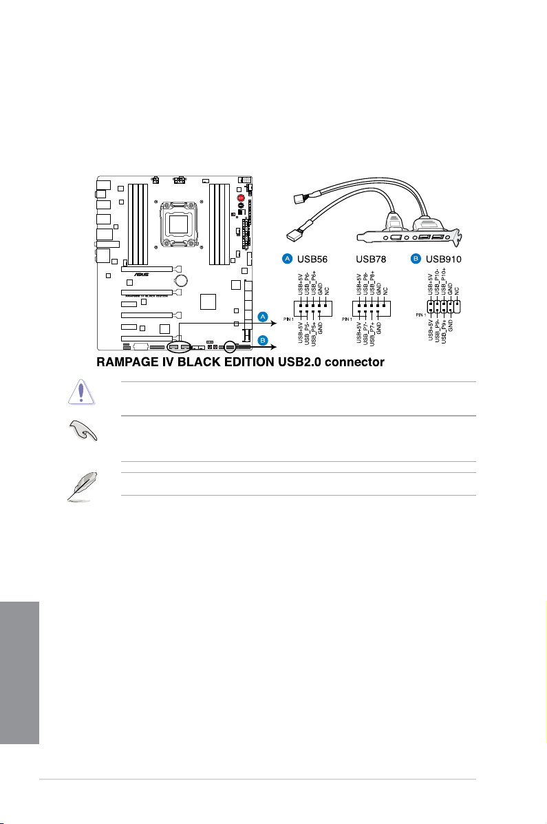
6. USB 2.0 connectors (10-1 pin USB56; USB78; USB910)
These connectors are for USB 2.0 ports. Connect the USB module cable to any of
these connectors, then install the module to a slot opening at the back of the system
chassis. These USB connectors comply with USB 2.0 specication that supports up to
480 Mbps connection speed.
Never connect a 1394 cable to the USB connectors. Doing so will damage the
motherboard!
You can connect the front panel USB cable to the ASUS Q-Connector (USB) rst, and then
install the Q-Connector (USB) to the USB connector onboard if your chassis supports front
panel USB ports.
The USB 2.0 module is purchased separately.
Chapter 1
1-42
Chapter 1: Product introduction
Page 59

7. Digital audio connector (4-1 pin SPDIF_OUT)
This connector is for an additional Sony/Philips Digital Interface (S/PDIF) port(s).
Connect the S/PDIF Out module cable to this connector, then install the module to a
slot opening at the back of the system chassis.
The S/PDIF module is purchased separately.
ASUS RAMPAGE IV BLACK EDITION
Chapter 1
1-43
Page 60

8. CPU, chassis, and power fan connectors (4-pin CPU_FAN; 4-pin CPU_OPT;
4-pin CHA_FAN1/ CHA_FAN2/ CHA_FAN3; 4-pin OPT_FAN1/ OPT_FAN2 /
OPT_FAN3)
Connect the fan cables to the fan connectors on the motherboard, ensuring that the
black wire of each cable matches the ground pin of the connector.
Do not forget to connect the fan cables to the fan connectors. Insufcient air ow inside the
system may damage the motherboard components. These are not jumpers! Do not place
jumper caps on the fan connectors!
• The CPU_FAN connector supports the CPU fan of maximum 1A (12 W) fan power.
• If you install two VGA cards, we recommend that you plug the rear chassis fan cable
to the motherboard connector labeled CHA_FAN1, CHA_FAN2 or CHA_FAN3 for
better thermal environment.
Chapter 1
1-44
Chapter 1: Product introduction
Page 61

9. Front panel audio connector (10-1 pin AAFP)
This connector is for a chassis-mounted front panel audio I/O module that supports either
HD Audio or legacy AC`97 audio standard. Connect one end of the front panel audio I/O
module cable to this connector.
• We recommend that you connect a high-denition front panel audio module to this
connector to avail of the motherboard’s high-denition audio capability.
• If you want to connect a high-denition front panel audio module to this connector, set
the Front Panel Type item in the BIOS setup to [HD]; if you want to connect an AC'97
front panel audio module to this connector, set the item to [AC97]. By default, this
connector is set to [HD].
ASUS RAMPAGE IV BLACK EDITION
Chapter 1
1-45
Page 62

10. DirectKey connector (2-pin DRCT)
This connector is for the chassis-mounted button that supports the DirectKey function.
Connect the button cable that supports DirectKey, from the chassis to this connector on
the motherboard.
Ensure that your chassis comes with the extra button cable that supports the DirectKey
feature. Refer to the technical documentation that came with the chassis for details.
11. ROG Extension - ROG_EXT connector (18-1 pin ROG_EXT)
This connector is for the OC Panel and other ROG accessories supporting the
ROG_EXT connector. The OC Panel allows you to perform overclocking without going
to the BIOS settings, loading the OS, or using overclocking software utilities.
Chapter 1
1-46
Chapter 1: Product introduction
Page 63

12. TPM connector (20-1 pin TPM)
This connector supports a Trusted Platform Module (TPM) system, which securely
store keys, digital certicates, passwords and data. A TPM system also helps enhance
the network security, protects digital identities, and ensures platform integrity.
13. Chassis intrusion connector (4-1 pin CHASSIS)
This connector is for a chassis-mounted intrusion detection sensor or switch. Connect
one end of the chassis intrusion sensor or switch cable to this connector. The chassis
intrusion sensor or switch sends a high-level signal to this connector when a chassis
component is removed or replaced. The signal is then generated as a chassis intrusion
event.
By default, the pin labeled “Chassis Signal” and “Ground” are shorted with a jumper
cap. Remove the jumper caps only when you intend to use the chassis intrusion
detection feature.
ASUS RAMPAGE IV BLACK EDITION
Chapter 1
1-47
Page 64

14. ATX power connectors (24-pin EATXPWR; 4-pin EATX12V_1; 4-pin EZ_PLUG;
8-pin EATX12V_2)
These connectors are for ATX power supply plugs. The power supply plugs are designed to
t these connectors in only one orientation. Find the proper orientation and push down rmly
until the connectors completely t.
• For a fully congured system, we recommend that you use a power supply unit
(PSU) that complies with ATX 12 V Specication 2.0 (or later version) and provides a
minimum power of 450 W.
• Do not forget to connect the 4-pin/8-pin EATX12 V power plug; otherwise, the system
will not boot.
• Connect the 4-pin EZ_PLUG power plugs to ensure sufcient power supply when you
install multiple graphics cards.
• Use of a PSU with a higher power output is recommended when conguring a system
with more power-consuming devices. The system may become unstable or may not
boot up if the power is inadequate.
• If you want to use two or more high-end PCI Express x16 cards, use a PSU with 1000W
power or above to ensure the system stability.
• If you are uncertain about the minimum power supply requirement for your system,
refer to the Recommended Power Supply Wattage Calculator at
http://support.asus.com/PowerSupplyCalculator/PSCalculator.aspx?
SLanguage=en-us for details.
Chapter 1
1-48
Chapter 1: Product introduction
Page 65

15. System panel connector (20-8 pin PANEL)
This connector supports several chassis-mounted functions.
• System power LED (2-pin PLED)
This 2-pin connector is for the system power LED. Connect the chassis power LED cable
to this connector. The system power LED lights up when you turn on the system power,
and blinks when the system is in sleep mode.
• Hard disk drive activity LED (2-pin IDE_LED)
This 2-pin connector is for the HDD Activity LED. Connect the HDD Activity LED cable
to this connector. The IDE LED lights up or ashes when data is read from or written to
the HDD.
• System warning speaker (4-pin SPEAKER)
This 4-pin connector is for the chassis-mounted system warning speaker. The speaker
allows you to hear system beeps and warnings.
• ATX power button/soft-off button (2-pin PWRSW)
This connector is for the system power button. Pressing the power button turns the
system on or puts the system in sleep or soft-off mode depending on the BIOS settings.
Pressing the power switch for more than four seconds while the system is ON turns the
system OFF.
• Reset button (2-pin RESET)
This 2-pin connector is for the chassis-mounted reset button for system reboot without
turning off the system power.
ASUS RAMPAGE IV BLACK EDITION
Chapter 1
1-49
Page 66

1.2.10 ProbeIt
The ROG ProbeIt allows you to detect your system’s current voltage and OC settings. Use a
multimeter to measure the ProbeIt points even during overclocking.
See the illustration below to locate the respective ProbeIt points.
Using ProbeIt
You may connect the multitester to the motherboard as shown on the following gure.
Chapter 1
1-50
The illustration above are for reference only, the actual motherboard layout and measure
points location may differ by models.
Chapter 1: Product introduction
Page 67

Chapter 2: Basic Installation
Basic Installation
2.1 Building your PC system
2.1.1 Motherboard installation
The diagrams in this section are for reference only. The motherboard layout may vary with
models, but the installation steps are the same for all models.
1. Install the ASUS Q-Shield to the chassis rear I/O panel.
2
2. Place the motherboard into the chassis, ensuring that its rear I/O ports are aligned to
the chassis’ rear I/O panel.
ASUS RAMPAGE IV BLACK EDITION
Chapter 2
2-1
Page 68

3. Place nine screws into the holes indicated by circles to secure the motherboard to the
chassis.
Chapter 2
2-2
DO NOT overtighten the screws! Doing so can damage the motherboard.
Chapter 2: Basic Installation
Page 69

2.1.2 CPU installation
B
A
B
C
A
B
A
Please note the order in opening/ closing the double latch. Follow the instructions printed on
the metal sealing hatch or the illustrations shown below in this manual. The plastic cap will pop
up automatically once the CPU is in place and the hatch properly sealed down.
1 2
3 4
ASUS RAMPAGE IV BLACK EDITION
Chapter 2
2-3
Page 70

B
A
B
A
5 6
7 8
Triangle mark
Triangle mark
9
Chapter 2
2-4
Chapter 2: Basic Installation
Page 71

2.1.3 CPU heatsink and fan assembly installation
Apply the Thermal Interface Material to the
CPU heatsink and CPU before you install
the heatsink and fan, if necessary.
To install the CPU heatsink and fan assembly
ASUS RAMPAGE IV BLACK EDITION
Chapter 2
2-5
Page 72

To replace the LGA2011 CPU pad (X-Socket)
• The X-Socket is a unique ROG feature that allows user to use their LGA 1366 cooler
on the LGA 2011 motherboard.
• For the detailed QVL list, visit
http://event.asus.com/2011/rog/X-Socket/.
1 2
3 4
5
Chapter 2
2-6
Chapter 2: Basic Installation
Page 73

2.1.4 DIMM installation
1
2
3
To remove a DIMM
B
ASUS RAMPAGE IV BLACK EDITION
A
Chapter 2
2-7
Page 74

2.1.5 ATX Power connection
1
2
OR OR
Chapter 2
2-8
Chapter 2: Basic Installation
Page 75

2.1.6 SATA device connection
1
OR
2
ASUS RAMPAGE IV BLACK EDITION
Chapter 2
2-9
Page 76

2.1.7 Front I/O Connector
To install ASUS Q-Connector
1
2
To install USB 2.0 connector To install front panel audio connector
AAFP
To install USB 3.0 connector
Chapter 2
2-10
USB 2.0
USB 3.0
Chapter 2: Basic Installation
Page 77

2.1.8 Expansion Card installation
To install PCIe x16 cards
To install PCIe x1 cards
ASUS RAMPAGE IV BLACK EDITION
Chapter 2
2-11
Page 78

2.1.9 Wi-Fi antenna installation
POWER eSATA 6G
S/PDIF
USB3.0
USB BIOS Flashback
USB3.0
REAR
SPK
CTR
BASS
LINE
IN
KY
FRONTMIC IN
IO Shield
Installing the ASUS 2T2R dual band W-Fi antenna
Connect the bundled ASUS 2T2R dual band Wi-Fi antenna connector to the Wi-Fi ports at
the back of the chassis.
• Ensure that the ASUS 2T2R dual band Wi-Fi antenna is securely installed to the Wi-Fi
ports.
• Ensure to install the Bluetooth and Wi-Fi driver before installing the Wi-Fi GO!
software.
Chapter 2
2-12
Chapter 2: Basic Installation
Page 79

2.2 BIOS update utility
USB BIOS Flashback
USB BIOS Flashback allows you to easily update the BIOS without entering the existing
BIOS or operating system. Simply insert a USB storage device to the USB port specially
allocated for the USB BIOS Flashback feature then press the ROG Connect button for three
seconds. The BIOS will be updated automatically.
To use USB BIOS Flashback:
1. Download the latest BIOS le from the ASUS website
2. Extract and rename the BIOS image le to
3. Copy
4. Turn off the system and insert the USB storage device to the ROG Connect port.
5. Press the ROG Connect button and release when a ashing light appears, which
6. Wait until the light goes out, indicating that the BIOS updating process is completed.
R4BE.CAP to the root directory of the USB ash disk drive.
indicates that the BIOS Flashback function is enabled.
USB BIOS Flashback/ ROG Connect portROG Connect button
R4BE.CAP.
For more BIOS update utilities in BIOS setup, refer to the section Updating BIOS in
Chapter 3.
• DO NOT unplug portable disk, power system, or press the CLR_CMOS button while
BIOS update is ongoing, otherwise update will be interrupted. In case of interruption,
please follow the steps again.
• Updating BIOS may have risks. If the BIOS program is damaged during the process
and results to the system’s failure to boot up, please contact your local ASUS Service
Center.
ASUS RAMPAGE IV BLACK EDITION
Chapter 2
2-13
Page 80

2.3 Motherboard rear and audio connections
2.3.1 Rear I/O connection
Rear panel connectors
1. PS/2 mouse and keyboard port
2. Clear CMOS button
3. USB 2.0 ports 3 and 4 (The ROG Connect port is the port on top.)
4. USB 3.0 ports 3 and 4
5. Intel® LAN (RJ-45) port**
6. Wi-Fi 802.11 a/b/g/n/ac Bluetooth V4.0*
7. USB 2.0 ports 1 and 2
8. ROG Connect button
9.
Chapter 2
USB 3.0 ports 1 and 2
10. External SATA 6.0 Gb/s ports 1 and 2
11. USB 3.0 ports 5 and 6
12. Audio I/O ports with Optical S/PDIF Out port***
*, **, and ***: Refer to the tables on the next page for Bluetooth/Wi-Fi module LEDs, LAN port LEDs, and audio port
denitions.
2-14
Chapter 2: Basic Installation
Page 81
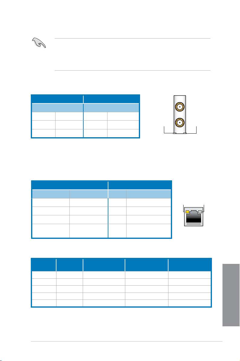
• USB 3.0 devices can only be used as data storage only.
• We strongly recommend that you connect USB 3.0 devices to USB 3.0 ports for faster
and better performance for your USB 3.0 devices.
• When using the external SATA port, ensure that you use a compatible connector.
*Bluetooth and Wi-Fi module LED indications
Wi-Fi LED Bluetooth LED
Status Description Status Description
Off No link Off No link
Green Linked Blue Linked
Blinking Data activity
* The Bluetooth word mark and logos are owned by Bluetooth SIG, Inc. and any use of such mark by ASUSTeK
Computer Inc. is under license. Other trademarks and trade names are those of their respective owners.
Wi-Fi
LED
Wi-Fi 802.11 a/b/g/n/ac,
Bluetooth v4.0/3.0 + HS
Bluetooth
LED
** LAN ports LED indications
Activity Link LED Speed LED
Status Description Status Description
Off
Orange
Orange (Blinking)
Orange (Blinking
then steady)
No link Off 10 Mbps connection
Linked Orange 100 Mbps connection
Data activity Green 1 Gbps connection
Ready to wake up
from S5 mode
ACT/LINK
LED
LAN port
SPEED
LED
** Audio 2, 4, 6 or 8-channel conguration
Port
Light Blue Line In Line In Line In Side Speaker Out
Lime Line Out Front Speaker Out Front Speaker Out Front Speaker Out
Pink Mic In Mic In Mic In Mic In
Orange – – Center/Subwoofer Center/Subwoofer
Black – Rear Speaker Out Rear Speaker Out Rear Speaker Out
ASUS RAMPAGE IV BLACK EDITION
Headset
2-channel
4-channel 6-channel 8-channel
Chapter 2
2-15
Page 82

2.3.2 Audio I/O connections
Audio I/O ports
Connect to Headphone and Mic
Connect to Stereo Speakers
Connect to 2.1 channel Speakers
Chapter 2
2-16
Chapter 2: Basic Installation
Page 83

Connect to 4.1 channel Speakers
Connect to 5.1 channel Speakers
Connect to 7.1 channel Speakers
ASUS RAMPAGE IV BLACK EDITION
Chapter 2
2-17
Page 84

2.4 OC Panel
ON
OFFONOFF
OC
Start
Clear
Reset
OK
OC
Start
Clear
Reset
OK
ON
OFFONOFF
Start
Clear
Reset
OK
OC
The OC Panel is a device that allows you to perform overclocking without the need to go to
the BIOS settings or use software utilities. You can setup the OC Panel in an available 5.25inch drive bay on your computer chassis (Normal Mode) or as an external handheld console
on an “open-air” OC test bench (Extreme Mode.)
These modes are further explained in the succeeding subsections.
• Ensure that your system has adequate cooling designed for overclocking before using
the OC Panel.
• Ensure to update your OC Panel’s rmware. Visit www.asus.com for the latest
rmware and updates about the OC Panel.
• Ensure that you have installed ROG Connect Plus driver for the NORMAL Mode of the
OC Panel.
• When updating the OC Panel rmware, you have to disable the USB XHCI function in
BIOS. To do this, click Advanced > USB Conguration > Intel xHCI Mode then set
Intel xHCI Mode to [Disabled].
2.4.1 OC Panel Overview
Normal/Extreme
Mode Switch
CPU Level Up
Start Button
Value up Button
Left Arrow button
Clear button
Fan connectors 1,2
VGA hotwire connectors
VGA hotwire
Chapter 2
2-18
LCM Power Button
FanSpeed Control button
Subzero Sense
OK button
connector
Right Arrow button
Reset button
Value Down button
Fan connectors 3,4
Pause/Slow Mode
OC Panel cover
Chapter 2: Basic Installation
Page 85
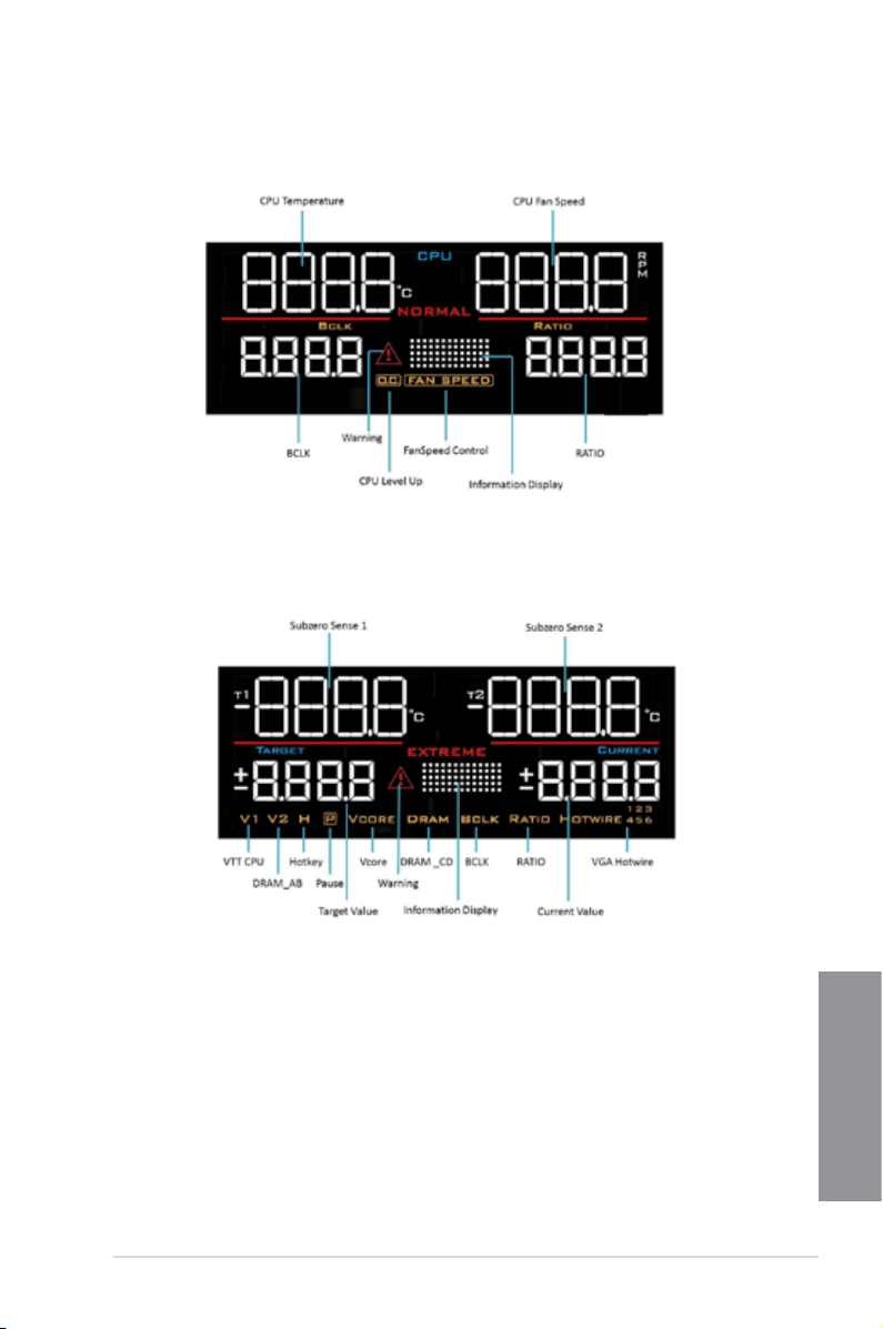
OC Panel LCM Display in Normal Mode
OC Panel LCM Display in Extreme Mode
ASUS RAMPAGE IV BLACK EDITION
Chapter 2
2-19
Page 86

2.4.2 Setting up your OC Panel in Normal Mode
R
eset
t
r
a
t
S
Clear
R
eset
OK
Ensure that you have installed ROG Connect Plus driver for the NORMAL Mode of the OC
Panel.
The OC Panel in Normal Mode mainly provides easy access buttons for increasing your
CPU’s frequency level, adjusting fan speeds and customizing overclocking proles. It also
displays vital information about your computer’s CPU temperature, ratio, base clock, CPU fan
speed (RPM).
To set up your OC Panel in Normal Mode:
1. Tilt the OC Panel LCM display until it is
perpendicular to the body of OC Panel.
2. Get the bundled OC Panel 5.25-inch drive
bay metal case and set of two (2) screws.
3. Align and insert the OC Panel into the OC
Panel 5.25-inch drive bay metal case.
The OC Panel ts in one orientation
only. If it does not t, try reversing it.
Chapter 2
2-20
Chapter 2: Basic Installation
Page 87

4. Secure the OC Panel to the OC Panel
5.25-inch drive bay metal case with the
two (2) screws.
Ensure that the OC Panel ts snugly
into the OC Panel 5.25-inch drive bay
metal case.
5. Shut down your computer.
6. Open your computer chassis and remove
the front cover of an available 5.25-inch
drive bay.
7. Align and insert the OC Panel and the
OC Panel 5.25-inch drive bay metal case
assembly into the drive bay.
8. Secure the OC Panel and the OC Panel
5.25-inch drive bay metal case assembly
into the drive bay with four (4) screws.
9. Connect the OC Panel data cable (A)
and a SATA Power cable (B) to the OC
Panel.
10. Locate the ROG_EXT connector on the motherboard and connect the OC Panel cable.
11. Boot your computer.
12. Press the OC Panel LCM Power button to turn on the OC Panel LCM display.
ASUS RAMPAGE IV BLACK EDITION
Chapter 2
2-21
Page 88

2.4.3 Setting up your OC Panel in Extreme Mode
The OC Panel in Extreme Mode is setup with an open chassis system or “open-air” OC
test bed assembly and enjoyed as a handheld console to perform overclocking and voltage
tuning.
When in Extreme Mode, you can enjoy more features including Subzero Sense and VGA
Hotwire. It also comes with some of the most commonly used voltage tuning presets that are
precongured for your convenience and optimum overclocking experience.
To setup the OC Panel in Extreme Mode:
1. Shut down your computer.
2. Connect the OC Panel cable (A) and a
SATA Power cable (B) to the OC Panel.
3. Locate the ROG_EXT connector on the
motherboard and connect the OC Panel
cable.
4. Boot your computer.
5. Press the OC Panel power button to turn on the OC Panel LCM display.
Chapter 2
2-22
Chapter 2: Basic Installation
Page 89
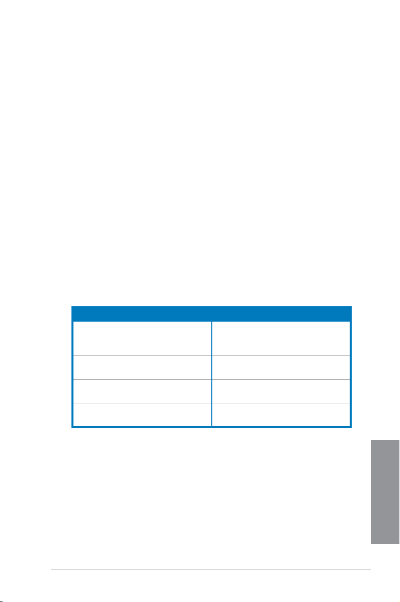
2.5 Starting up for the rst time
1. After making all the connections, replace the system case cover.
2. Ensure that all switches are off.
3. Connect the power cord to the power connector at the back of the system chassis.
4. Connect the power cord to a power outlet that is equipped with a surge protector.
5. Turn on the devices in the following order:
a. Monitor
b. External SCSI devices (starting with the last device on the chain)
c. System power
6. After applying power, the system power LED on the system front panel case lights up.
For systems with ATX power supplies, the system LED lights up when you press the
ATX power button. If your monitor complies with the “green” standards or if it has a
“power standby” feature, the monitor LED may light up or change from orange to green
after the system LED turns on.
The system then runs the power-on self tests (POST). While the tests are running, the
BIOS beeps (refer to the BIOS beep codes table) or additional messages appear on
the screen. If you do not see anything within 30 seconds from the time you turned on
the power, the system may have failed a power-on test. Check the jumper settings and
connections or call your retailer for assistance.
BIOS Beep Description
One short beep VGA detected
One continuous beep followed by two
short beeps then a pause (repeated)
One continuous beep followed by three
short beeps
One continuous beep followed by four
short beeps
Quick boot set to disabled
No keyboard detected
No memory detected
No VGA detected
Hardware component failure
7. At power on, hold down the <Delete> key to enter the BIOS Setup. Follow the
instructions in Chapter 3.
2.6 Turning off the computer
While the system is ON, press the power button for less than four seconds to put the system
on sleep mode or soft-off mode, depending on the BIOS setting. Press the power switch
for more than four seconds to let the system enter the soft-off mode regardless of the BIOS
setting.
ASUS RAMPAGE IV BLACK EDITION
Chapter 2
2-23
Page 90

Chapter 2
2-24
Chapter 2: Basic Installation
Page 91

Chapter 3: BIOS setup
BIOS setup
3
3.1 Knowing BIOS
The new ASUS UEFI BIOS is a Unied Extensible Interface that complies with UEFI
architecture, offering a user-friendly interface that goes beyond the traditional keyboard-
only BIOS controls to enable a more exible and convenient mouse input. You can easily
navigate the new UEFI BIOS with the same smoothness as your operating system. The
term “BIOS” in this user manual refers to “UEFI BIOS” unless otherwise specied.
BIOS (Basic Input and Output System) stores system hardware settings such as storage
device conguration, overclocking settings, advanced power management, and boot
device conguration that are needed for system startup in the motherboard CMOS. In
normal circumstances, the default BIOS settings apply to most conditions to ensure
optimal performance. DO NOT change the default BIOS settings except in the following
circumstances:
An error message appears on the screen during the system bootup and requests you to
•
run the BIOS Setup.
•
You have installed a new system component that requires further BIOS settings or
update.
Inappropriate BIOS settings may result to instability or boot failure. We strongly
recommend that you change the BIOS settings only with the help of a trained service
personnel.
When downloading or updating the BIOS le, rename it as R4BE.CAP for this
motherboard.
ASUS RAMPAGE IV BLACK EDITION
Chapter 3
3-1
Page 92

3.2 BIOS setup program
Use the BIOS Setup to update the BIOS or congure its parameters. The BIOS screen
include navigation keys and brief onscreen help to guide you in using the BIOS Setup
program.
Entering BIOS at startup
To enter BIOS Setup at startup, press <Delete> during the Power-On Self Test (POST). If you
do not press <Delete>, POST continues with its routines.
Entering BIOS Setup after POST
To enter BIOS Setup after POST:
• Press <Ctrl>+<Alt>+<Delete> simultaneously.
• Press the reset button on the system chassis.
• Press the DirectKey button on the motherboard. You can perform this option if the
DirectKey item is enabled in BIOS Setup. See the section about Boot Menu on
Chapter 3 for more information in enabling the DirectKey function in BIOS.
• Press the power button to turn the system off then back on. Do this option only if you
failed to enter BIOS Setup using the previous options.
- The BIOS setup screens shown in this section are for reference purposes only, and
may not exactly match what you see on your screen.
- Ensure that a USB mouse is connected to your motherboard if you want to use the
mouse to control the BIOS setup program.
- If the system becomes unstable after changing any BIOS setting, load the default
settings to ensure system compatibility and stability. Select the Load Optimized
Defaults item under the Exit menu or press hotkey <F5>. See the section about
Exit menu on Chapter 3 for more information.
- If the system fails to boot after changing any BIOS setting, try to clear the CMOS and
reset the motherboard to the default value. See the section about
Rear I/O Connection on Chapter 2 for information on how to erase the RTC RAM via
the Clear CMOS button.
BIOS menu screen
Chapter 3
The BIOS Setup program can be used under two modes: EZ Mode and Advanced Mode.
You can change modes from the Exit menu or from the Exit/Advanced Mode screen.
3-2
- The BIOS setup program does not support bluetooth devices.
Chapter 3: BIOS setup
Page 93

3.2.1 EZ Mode
The EZ Mode provides you an overview of the basic system information, and allows you to
select the display language, system performance mode and boot device priority. To access
the Advanced Mode, click Exit/Advanced Mode, then select Advanced Mode or press <F7>
hot key for the advanced BIOS settings.
The default screen for entering the BIOS setup program can be changed. For more
information, see the Setup Mode item of the Boot menu section on Chapter 3.
Displays the CPU
temperature and CPU
voltage output
Displays the shortcut
items
Selects the boot device priority
Power Saving mode
Displays the installed
DIMMs
Displays the Advanced
mode menus
Selects the display language of the
BIOS setup program
Normal mode
SATA
Information
ASUS Optimal
mode
Click to display all fan
speeds if available
Exits the BIOS setup program without saving
the changes, saves the changes and resets the
system, or enters the Advanced Mode
Boot Menu
Loads optimized default settings
Displays the system properties of the
selected mode
• The boot device options vary depending on the devices you installed to the system.
• The
Boot Menu (F8) button is available only when the boot device is installed to the
system.
ASUS RAMPAGE IV BLACK EDITION
Chapter 3
3-3
Page 94

3.2.2 Advanced Mode
The Advanced Mode provides advanced options for experienced end-users to congure
the BIOS settings. The gure below shows an example of the Advanced Mode. Refer to the
following sections for the detailed congurations.
To access the Advanced Mode, click Exit, then select Advanced Mode or press F7 hotkey.
Menu items
Menu barSubmenu items
Pop-up window
Conguration elds
Scroll bar
Menu bar
The menu bar on top of the screen has the following main items:
General help
Navigation keys
My Favorites
Chapter 3
Extreme Tweaker
Main For changing the basic system conguration
Advanced For changing the advanced system settings
Monitor
Boot For changing the system boot conguration
Tool For conguring options for special functions
Exit For selecting the exit options and loading default settings
3-4
For saving the frequently-used system settings and conguration
For changing the overclocking settings
For displaying the system temperature, power status, and changing
the fan settings
Chapter 3: BIOS setup
Page 95

Menu items
The highlighted item on the menu bar displays the specic items for that menu. For example,
selecting Main shows the Main menu items.
The other items (My Favorites, Extreme Tweaker, Advanced, Monitor, Boot, Tool, and Exit) on
the menu bar have their respective menu items.
Back button
This button appears when entering a submenu. Press <Esc> or use the USB mouse to click
this button to return to the previous menu screen.
Submenu items
A greater than sign (>) before each item on any menu screen means that the item has a
submenu. To display the submenu, select the item and press <Enter>.
Pop-up window
Select a menu item and press <Enter> to display a pop-up window with the conguration
options for that item.
Scroll bar
A scroll bar appears on the right side of a menu screen when there are items that do not t on
the screen. Press the Up/Down arrow keys or <Page Up> / <Page Down> keys to display the
other items on the screen.
Navigation keys
At the bottom right corner of the menu screen are the navigation keys for the BIOS setup
program. Use the navigation keys to select items in the menu and change the settings.
If you delete all shortcut items from the F3: Shortcut list, the default shortcut items will
reappear after your next startup.
General help
At the top right corner of the menu screen is a brief description of the selected item. Use
<F12> key to capture the BIOS screen and save it to the removable storage device.
Conguration elds
These elds show the values for the menu items. If an item is user-congurable, you can
change the value of the eld opposite the item. You cannot select an item that is not
user-congurable.
A congurable eld is highlighted when selected. To change the value of a eld, select it and
press <Enter> to display a list of options.
Quick Note button
This button allows you to enter notes of the activities that you have done in BIOS.
• The Quick Note function does not support the following keyboard functions: delete,
cut, copy and paste.
• You can only use the alphanumeric characters to enter your notes.
Last Modied button
This button shows the items that you last modied and saved in BIOS Setup.
ASUS RAMPAGE IV BLACK EDITION
Chapter 3
3-5
Page 96

3.3 My Favorites
MyFavorites is your personal space where you can easily save and access your favorite
BIOS items.
Adding items to My Favorites
To add frequently-used BIOS items to My Favorites:
1. Use the arrow keys to select an item that you want to add. When using a mouse, hover
the pointer to the item.
2. Press <F4> on your keyboard or right-click on your mouse to add the item to My
Favorites page.
Chapter 3
You cannot add the following items to My Favorites:
• Items with submenu options
• User-congurable items such as language and boot device order
• Conguration items such as Memory SPD Information, system time and date
3-6
Chapter 3: BIOS setup
Page 97

3.4 Extreme Tweaker menu
The Extreme Tweaker menu items allow you to congure overclocking-related items.
Be cautious when changing the settings of the Extreme Tweaker menu items. Incorrect eld
values can cause the system to malfunction.
The conguration options for this section vary depending on the CPU and DIMM model you
installed on the motherboard.
Scroll down to display other BIOS items.
Load Air-cooled Gamer’s OC Prole/ Load Water-cooled Gamer’s OC Prole
Load 160BCLK OC Prole/ Load 170BCLK OC Prole/
Load 180BCLK OC Prole/ Load 190BCLK OC Prole
Select any of these preset overclocking proles to load your preferred overclocking option.
The proles appearing on the BIOS screen may vary depending on the CPU installed on
your motherboard.
ASUS RAMPAGE IV BLACK EDITION
Chapter 3
3-7
Page 98

Ai Overclock Tuner [Auto]
Allows you to select the CPU overclocking options to achieve the desired CPU internal
frequency. Select any of these preset overclocking conguration options:
[Auto] Loads the optimal settings for the system.
[Manual] Allows you to individually set overclocking parameters.
[X.M.P.] If you install memory modules supporting the eXtreme Memory Prole
(X.M.P.) Technology, choose this item to set the proles supported by your
memory modules for optimizing the system performance.
The [X.M.P.] conguration option appears only when you install memory modules
supporting the eXtreme Memory Prole (X.M.P.) Technology.
CPU Level Up [Disabled]
Allows you to select a CPU level, and the related parameters will be automatically adjusted
according to the selected CPU level.
Conguration options: [Disabled] [Auto] [4.800G] [4.600G] [4.400G]
The conguration option and its values may vary depending on the CPU installed on your
motherboard.
CPU Core Ratio [Auto]
Allows you to set the CPU ratio and sync automatically, per core or all cores.
Conguration options: [Auto] [Sync All Cores] [Per Core]
When the CPU Core Ratio is set to [Sync All Cores], the following item appears.
1-Core Ratio Limit [Auto]
Allows you to set the 1-Core Ratio Limit.
[Auto] Select to apply the CPU default Turbo Ratio setting.
[Manual] Select to manually assign a value for the 1-Core Ratio limit. The
values of 2-core, 3-core, 4-core, 5-core, and 6-core ratio limits will be
automatically set to be lower than or equal to the value of the 1-core
Ratio limit.
1-Core Ratio Limit [Auto]
Allows you to set the 1-Core Ratio Limit.
[Auto] Select to apply the CPU default Turbo Ratio setting.
Chapter 3
[Manual] Select to manually assign a 1-Core Ratio Limit value that is higher
than or equal to the 2-Core Ratio Limit.
2-Core Ratio Limit [Auto]
Allows you to set the 2-Core Ratio Limit.
[Auto] Select to apply the CPU default Turbo Ratio setting.
[Manual] Select to manually assign a 2-Core Ratio Limit value that is higher
than or equal to the 3-Core Ratio Limit. 1-Core Limit must not be set to
[Auto].
3-8
When the CPU Core Ratio is set to [Per Core], the following item appears:
Chapter 3: BIOS setup
Page 99

3-Core Ratio Limit [Auto]
Allows you to set the 3-Core Ratio Limit.
[Auto] Select to apply the CPU default Turbo Ratio setting.
[Manual] Select to manually assign a 3-Core Ratio Limit value that is higher
han or equal to the 4-Core Ratio Limit. 1-Core/2-Core Ratio Limit must
not be set to [Auto].
4-Core Ratio Limit [Auto]
Allows you to set the 4 Core Ratio Limit
[Auto] Select to apply the CPU default Turbo Ratio setting
[Manual] Select to manually assign a 4-Core Ratio Limit value that is higher
than or equal to the 3-Core Ratio Limit. 1-Core/2-Core/3-Core Limit
must not be set to [Auto].
5-Core Ratio Limit [Auto]
Allows you to set the 5-Core Ratio Limit.
[Auto] Select to apply the CPU default Turbo Ratio setting.
[Manual] Select to manually assign a 5-Core Ratio Limit value that is higher
han or equal to the 4-Core Ratio Limit. 1-Core/2-Core/3-Core/4-Core
Ratio Limit must not be set to [Auto].
6-Core Ratio Limit [Auto]
Allows you to set the 6 Core Ratio Limit
[Auto] Select to apply the CPU default Turbo Ratio setting
[Manual] Select to manually assign a 6-Core Ratio Limit value that is higher
than or equal to the 5-Core Ratio Limit. 1-Core/2-Core/3-Core /
4-Core/5-Core Limit must not be set to [Auto].
Internal PLL Overvoltage [Auto]
Allows you to enable the internal PLL voltage for K-SKU CPUs to get the extreme
overclocking capability.
Conguration options: [Auto] [Enabled] [Disabled]
DRAM Frequency [Auto]
Allows you to set the memory operating frequency. The conguration options vary with the
BCLK/CPU Strap Frequency item settings.
Xtreme Tweaking [Disabled]
Allows you to enable or disable Xtreme Tweaking that helps improve some benchmark
performance.
Conguration options: [Enabled] [Disabled]
ASUS RAMPAGE IV BLACK EDITION
Chapter 3
3-9
Page 100

EPU Power Saving Mode [Disabled]
Allows you to enable or disable the EPU power saving function.
Conguration options: [Disabled] [Enabled]
The following item only appears when you set EPU Power Saving Mode to [Enabled].
EPU Setting [Auto]
Allows you to select the EPU power saving function.
Conguration options: [Auto] [Light Power Saving] [Medium Power Saving]
[Max Power Saving]
DRAM Timing Control
The subitems in this menu allow you to set the DRAM timing control features. Use the <+>
and <-> keys to adjust the value. To restore the default setting, type [auto] using the keyboard
and press the <Enter> key.
Memory Presets
This item allows you to select and load a memory preset or timing prole from a
redened list. The congurations of the memory presets are provided by the ROG OC
expert team. Users can load the proles before performing overclocking or DRAM
tweaking.
Rampage Tweak [Auto]
This item allows you to choose the mode that is supported by Rampage Tweak when
you want to ne tune the DRAM of the system. Mode 1 helps you with the DRAM
performance, Mode 2 helps you in overclocking and system performance, and Mode 3
is suitable for Ivy Biridge-E.
[Auto] Automatically selects the mode.
[Mode 1] Memory compatibility.
[Mode 2] Overclocking and performance.
[Mode 3] Ivy Bridge-E compatability
Primary Timings
DRAM CAS# Latency [Auto]
Conguration options: [Auto] [1] – [31]
Chapter 3
3-10
DRAM RAS# to CAS# Delay [Auto]
Conguration options: [Auto] [1] – [31]
DRAM RAS# PRE Time [Auto]
Conguration options: [Auto] [1] – [15]
DRAM RAS# ACT Time [Auto]
Conguration options: [Auto] [1] – [63]
DRAM Command Rate [Auto]
Conguration options: [Auto] [1] – [3]
Changing the values in this menu may cause the system to become unstable! If this
happens, revert to the default settings.
Chapter 3: BIOS setup
 Loading...