


Rampage III
Extreme
Motherboard

E5246
First Edition
March 2010
Copyright © 2010 ASUSTeK COMPUTER INC. All Rights Reserved.
No part of this manual, including the products and software described in it, may be reproduced,
transmitted, transcribed, stored in a retrieval system, or translated into any language in any form or by any
means, except documentation kept by the purchaser for backup purposes, without the express written
permission of ASUSTeK COMPUTER INC. (“ASUS”).
Product warranty or service will not be extended if: (1) the product is repaired, modified or altered, unless
such repair, modification of alteration is authorized in writing by ASUS; or (2) the serial number of the
product is defaced or missing.
ASUS PROVIDES THIS MANUAL “AS IS” WITHOUT WARRANTY OF ANY KIND, EITHER EXPRESS
OR IMPLIED, INCLUDING BUT NOT LIMITED TO THE IMPLIED WARRANTIES OR CONDITIONS OF
MERCHANTABILITY OR FITNESS FOR A PARTICULAR PURPOSE. IN NO EVENT SHALL ASUS, ITS
DIRECTORS, OFFICERS, EMPLOYEES OR AGENTS BE LIABLE FOR ANY INDIRECT, SPECIAL,
INCIDENTAL, OR CONSEQUENTIAL DAMAGES (INCLUDING DAMAGES FOR LOSS OF PROFITS,
LOSS OF BUSINESS, LOSS OF USE OR DATA, INTERRUPTION OF BUSINESS AND THE LIKE),
EVEN IF ASUS HAS BEEN ADVISED OF THE POSSIBILITY OF SUCH DAMAGES ARISING FROM ANY
DEFECT OR ERROR IN THIS MANUAL OR PRODUCT.
SPECIFICATIONS AND INFORMATION CONTAINED IN THIS MANUAL ARE FURNISHED FOR
INFORMATIONAL USE ONLY, AND ARE SUBJECT TO CHANGE AT ANY TIME WITHOUT NOTICE,
AND SHOULD NOT BE CONSTRUED AS A COMMITMENT BY ASUS. ASUS ASSUMES NO
RESPONSIBILITY OR LIABILITY FOR ANY ERRORS OR INACCURACIES THAT MAY APPEAR IN THIS
MANUAL, INCLUDING THE PRODUCTS AND SOFTWARE DESCRIBED IN IT.
Products and corporate names appearing in this manual may or may not be registered trademarks or
copyrights of their respective companies, and are used only for identification or explanation and to the
owners’ benefit, without intent to infringe.
ii

Contents
Notices ....................................................................................................... viii
Safety information ..................................................................................... xii
About this guide ....................................................................................... xiv
Rampage III Extreme specications summary ...................................... xvi
Chapter 1: Product introduction
1.1 Welcome! ...................................................................................... 1-1
1.2 Package contents ......................................................................... 1-1
1.3 Special features ............................................................................ 1-2
1.3.1 Product highlights ........................................................... 1-2
1.3.2 ROG Intelligent Performance & Overclocking features ... 1-3
1.3.3 ROG unique features ...................................................... 1-6
1.3.4 ASUS special features .................................................... 1-6
Chapter 2: Hardware information
2.1 Before you proceed ..................................................................... 2-1
2.2 Motherboard overview ................................................................. 2-6
2.2.1 Motherboard layout ......................................................... 2-6
2.2.2 Layout contents ............................................................... 2-7
2.2.3 Placement direction ........................................................ 2-8
2.2.4 Screw holes .................................................................... 2-8
2.3 Central Processing Unit (CPU) ................................................... 2-9
2.3.1 Installing the CPU ........................................................... 2-9
2.3.2 Installing the CPU heatsink and fan .............................. 2-12
2.3.3 Uninstalling the CPU heatsink and fan ......................... 2-13
2.4 System memory ......................................................................... 2-14
2.4.1 Overview ....................................................................... 2-14
2.4.2 Memory configurations .................................................. 2-15
2.4.3 Installing a DIMM .......................................................... 2-24
2.4.4 Removing a DIMM ........................................................ 2-24
2.5 Expansion slots .......................................................................... 2-25
2.5.1 Installing an expansion card ......................................... 2-25
2.5.2 Configuring an expansion card ..................................... 2-25
2.5.3 Interrupt assignments ................................................... 2-26
2.5.4 PCI slot ......................................................................... 2-27
2.5.5 PCI Express x4 slot ....................................................... 2-27
2.5.6 PCI Express x16 slots ................................................... 2-27
2.6 Jumper ........................................................................................ 2-29
iii

Contents
2.7 RC Bluetooth card ...................................................................... 2-31
2.8 I/O shield Installation ................................................................. 2-32
2.9 Connectors ................................................................................. 2-33
2.9.1 Rear panel connectors .................................................. 2-33
2.9.2 ROG Connect switch and RC Bluetooth switch ............ 2-34
2.9.3 Audio I/O connections ................................................... 2-36
2.9.4 Internal connectors ....................................................... 2-39
2.9.5 Onboard switches ......................................................... 2-49
2.9.6 ProbeIt .......................................................................... 2-52
2.10 Starting up for the rst time ...................................................... 2-53
2.11 Turning off the computer ........................................................... 2-54
2.11.1 Using the OS shut down function .................................. 2-54
2.11.2 Using the dual function power switch ............................ 2-54
Chapter 3: BIOS setup
3.1 Managing and updating your BIOS ............................................ 3-1
3.1.1 ASUS Update utility ........................................................ 3-1
3.1.2 ASUS EZ Flash 2 utility ................................................... 3-4
3.1.3 ASUS CrashFree BIOS 3 utility ...................................... 3-5
3.2 BIOS setup program .................................................................... 3-6
3.2.1 BIOS menu screen .......................................................... 3-7
3.2.2 Menu bar ......................................................................... 3-7
3.2.3 Navigation keys ............................................................... 3-7
3.2.4 Menu items ..................................................................... 3-8
3.2.5 Submenu items ............................................................... 3-8
3.2.6 Configuration fields ......................................................... 3-8
3.2.7 Pop-up window ............................................................... 3-8
3.2.8 Scroll bar ......................................................................... 3-8
3.2.9 General help ................................................................... 3-8
3.3 Extreme Tweaker menu ............................................................... 3-9
3.3.1 CPU Level Up [Auto] ..................................................... 3-10
3.3.2 Sync Mode [Enabled] .................................................... 3-10
3.3.3 Ai Overclock Tuner [Auto] ............................................. 3-10
3.3.4 CPU Ratio Setting [Auto] .............................................. 3-10
3.3.5 CPU Turbo Power Limit [Disabled] ................................3-11
3.3.6 CPU Configuration .........................................................3-11
3.3.7 BCLK Frequency [XXX] .................................................3-11
iv

Contents
3.3.8 PCIE Frequency [XXX] ..................................................3-11
3.3.9 DRAM Frequency [Auto] ................................................3-11
3.3.10 UCLK Frequency [Auto] .................................................3-11
3.3.11 QPI Link Data Rate [Auto] ..............................................3-11
3.3.12 DRAM Timing Control ................................................... 3-12
3.3.13 CPU Differential Amplitude [Auto] ................................. 3-13
3.3.14 CPU Clock Skew [Auto] ................................................ 3-14
3.3.15 IOH Clock Skew [Auto] ................................................. 3-14
3.3.16 Digi+ PWR Mode [T-Balanced] ..................................... 3-14
3.3.17 PWM Volt. Control [Auto] .............................................. 3-14
3.3.18 Load-Line Calibration [Auto] ......................................... 3-14
3.3.19 CPU Voltage OCP [Enabled]......................................... 3-14
3.3.20 CPU PWM Frequency [Auto] ........................................ 3-14
3.3.21 Extreme OV [Disabled] ................................................. 3-14
3.3.22 CPU Voltage Control [Absolute (VID)] ......................... 3-14
3.3.23 CPU Voltage [Auto] ...................................................... 3-15
3.3.24 CPU PLL Voltage [Auto] ................................................ 3-15
3.3.25 QPI Loadline Calibration [Auto] ..................................... 3-15
3.3.26 QPI/DRAM Core Voltage [Auto] .................................... 3-15
3.3.27 IOH Voltage [Auto] ........................................................ 3-15
3.3.28 IOH PCIE Voltage [Auto] ............................................... 3-15
3.3.29 DRAM Bus Voltage [Auto] ............................................. 3-15
3.3.30 DRAM REF Voltages .................................................... 3-15
3.3.31 CPU Spread Spectrum [Auto] ....................................... 3-16
3.3.32 PCIE Spread Spectrum [Auto] ...................................... 3-16
3.4 Main menu .................................................................................. 3-17
3.4.1 System Time [xx:xx:xx] ................................................. 3-17
3.4.2 System Date [Day xx/xx/xxxx] ....................................... 3-17
3.4.3 Language [English] ....................................................... 3-17
3.4.4 SATA 1–6 .........................................................................................3-18
3.4.5 Storage Configuration ................................................... 3-20
3.4.6 AHCI Configuration ....................................................... 3-21
3.4.7 System Information ....................................................... 3-21
3.5 Advanced menu ......................................................................... 3-22
3.5.1 CPU Configuration ........................................................ 3-22
3.5.2 Chipset .......................................................................... 3-25
3.5.3 Onboard Devices Configuration .................................... 3-26
v

Contents
3.5.4 USB Configuration ........................................................ 3-28
3.5.5 PCIPnP ......................................................................... 3-29
3.5.6 LED Control .................................................................. 3-30
3.5.7 iROG Configuration ....................................................... 3-31
3.5.8 ROG Connect ............................................................... 3-32
3.6 Power menu ................................................................................ 3-33
3.6.1 Suspend Mode [Auto] ................................................... 3-33
3.6.2 Repost Video on S3 Resume [No] ................................ 3-33
3.6.3 ACPI 2.0 Support [Disabled] ......................................... 3-33
3.6.6 APM Configuration ........................................................ 3-34
3.6.4 ACPI APIC Support [Enabled] ....................................... 3-34
3.6.5 EuP Ready [Disabled] ................................................... 3-34
3.6.7 Hardware Monitor ......................................................... 3-36
3.7 Boot menu .................................................................................. 3-39
3.7.1 Boot Device Priority ...................................................... 3-39
3.7.2 Boot Settings Configuration .......................................... 3-40
3.7.3 Security ......................................................................... 3-41
3.8 Tools menu ................................................................................. 3-43
3.8.1 ASUS EZ Flash 2 .......................................................... 3-43
3.8.2 ASUS O.C. Profile ......................................................... 3-44
3.8.3 GO_Button File ............................................................. 3-46
3.8.4 BIOS FlashBack ............................................................ 3-47
3.9 Exit menu .................................................................................... 3-48
Chapter 4: Software support
4.1 Installing an operating system ................................................... 4-1
4.2 Support DVD information ............................................................ 4-1
4.2.1 Running the support DVD ............................................... 4-1
4.2.2 Drivers menu ................................................................... 4-2
4.2.3 Utilities menu .................................................................. 4-3
4.2.4 Make disk menu .............................................................. 4-4
4.2.5 Manual menu .................................................................. 4-4
4.2.6 Video menu ..................................................................... 4-5
4.2.7 ASUS Contact information .............................................. 4-5
4.2.8 Other information ............................................................ 4-6
4.2.2 Obtaining the software manuals ..................................... 4-8
4.3 Software information ................................................................... 4-9
vi

Contents
4.3.1 Realtek HD Audio Manager ............................................ 4-9
4.3.2 ASUS PC Probe II ......................................................... 4-15
4.3.3 ASUS AI Suite ............................................................... 4-21
4.3.4 ASUS Fan Xpert ........................................................... 4-23
4.3.5 CPU Level Up ............................................................... 4-24
4.3.6 TurboV EVO .................................................................. 4-24
4.3.7 ROG Connect ............................................................... 4-26
4.4 RAID congurations .................................................................. 4-28
4.4.1 RAID definitions ............................................................ 4-28
4.4.2 Installing Serial ATA hard disks ..................................... 4-29
4.4.3 Setting the RAID item in BIOS ...................................... 4-29
4.4.4 Intel® Matrix Storage Manager option ROM utility ......... 4-29
4.5 Creating a RAID driver disk ....................................................... 4-33
4.5.1 Creating a RAID driver disk without entering the OS .... 4-33
4.5.2 Creating a RAID driver disk in Windows
4.5.3 Installing the RAID driver during
Windows® OS installation .............................................. 4-34
4.5.4 Using a USB floppy disk drive ....................................... 4-34
Chapter 5: ATI® CrossFireX™ technology support
5.1 ATI® CrossFireX™ technology .................................................... 5-1
5.1.1 Requirements .................................................................. 5-1
5.1.2 Before you begin ............................................................. 5-1
5.1.3 Installing CrossFireX graphics cards .............................. 5-2
5.1.4 Installing the device drivers ............................................. 5-3
5.1.5 Enabling the ATI® CrossFireX™ technology ................... 5-3
5.2 NVIDIA® SLI™ technology ........................................................... 5-5
5.2.1 Requirements .................................................................. 5-5
5.2.2 Installing two SLI-ready graphics cards .......................... 5-5
5.2.3 Installing the device drivers ............................................. 5-6
5.2.4 Enabling the NVIDIA® SLI™ technology ......................... 5-6
® ........................................... 4-33
Appendix: Reference information
A.1 Debug code table .........................................................................A-1
A.2 Qualied Vendors Lists (QVL) for BIOS FlashBack ..................A-4
A.3 Qualied Vendors Lists (QVL) for RC Bluetooth .......................A-4
A.4 Qualied Vendors Lists (QVL) for
500W Power Supply or above ....................................................A-5
vii

Notices
Federal Communications Commission Statement
This device complies with Part 15 of the FCC Rules. Operation is subject to the
following two conditions:
• This device may not cause harmful interference, and
• This device must accept any interference received including interference that
may cause undesired operation.
This equipment has been tested and found to comply with the limits for a
Class B digital device, pursuant to Part 15 of the FCC Rules. These limits are
designed to provide reasonable protection against harmful interference in a
residential installation. This equipment generates, uses and can radiate radio
frequency energy and, if not installed and used in accordance with manufacturer’s
instructions, may cause harmful interference to radio communications. However,
there is no guarantee that interference will not occur in a particular installation. If
this equipment does cause harmful interference to radio or television reception,
which can be determined by turning the equipment off and on, the user is
encouraged to try to correct the interference by one or more of the following
measures:
• Reorient or relocate the receiving antenna.
• Increase the separation between the equipment and receiver.
• Connect the equipment to an outlet on a circuit different from that to which the
receiver is connected.
• Consult the dealer or an experienced radio/TV technician for help.
The use of shielded cables for connection of the monitor to the graphics card is
required to assure compliance with FCC regulations. Changes or modifications
to this unit not expressly approved by the party responsible for compliance
could void the user’s authority to operate this equipment.
FCC Radio Frequency (RF) Exposure Caution Statement
Any changes or modifications not expressly approved by the party responsible
for compliance could void the user’s authority to operate this equipment. “The
manufacture declares that this device is limited to Channels 1 through 11 in the
2.4GHz frequency by specified firmware controlled in the USA.”
This equipment complies with FCC radiation exposure limits set forth for an
uncontrolled environment. To maintain compliance with FCC RF exposure
compliance requirements, please avoid direct contact to the transmitting antenna
during transmitting. End users must follow the specific operating instructions for
satisfying RF exposure compliance.
viii

RF exposure warning
This equipment must be installed and operated in accordance with provided
instructions and the antenna(s) used for this transmitter must be installed to
provide a separation distance of at least 20 cm from all persons and must not
be co-located or operating in conjunction with any other antenna or transmitter.
End-users and installers must be provide with antenna installation instructions and
transmitter operating conditions for satisfying RF exposure compliance.
Declaration of Conformity (R&TTE directive 1999/5/EC)
The following items were completed and are considered relevant and sufficient:
• Essential requirements as in [Article 3]
• Protection requirements for health and safety as in [Article 3.1a]
• Testing for electric safety according to [EN 60950]
• Protection requirements for electromagnetic compatibility in [Article 3.1b]
• Testing for electromagnetic compatibility in [EN 301 489-1] & [EN 301 489-17]
• Effective use of the radio spectrum as in [Article 3.2]
• Radio test suites according to [EN 300 328-2]
CE Marking
CE marking for devices without wireless LAN/Bluetooth
The shipped version of this device complies with the requirements of the EEC
directives 2004/108/EC “Electromagnetic compatibility” and 2006/95/EC “Low
voltage directive”.
CE marking for devices with wireless LAN/ Bluetooth
This equipment complies with the requirements of Directive 1999/5/EC of the
European Parliament and Commission from 9 March, 1999 governing Radio and
Telecommunications Equipment and mutual recognition of conformity.
ix

Wireless Operation Channel for Different Domains
N. America 2.412-2.462 GHz Ch01 through CH11
Japan 2.412-2.484 GHz Ch01 through Ch14
Europe ETSI 2.412-2.472 GHz Ch01 through Ch13
France Restricted Wireless Frequency Bands
Some areas of France have a restricted frequency band. The worst case maximum
authorized power indoors are:
• 10mW for the entire 2.4 GHz band (2400 MHz–2483.5 MHz)
• 100mW for frequencies between 2446.5 MHz and 2483.5 MHz
Channels 10 through 13 inclusive operate in the band 2446.6 MHz to 2483.5
MHz.
There are few possibilities for outdoor use: On private property or on the private
property of public persons, use is subject to a preliminary authorization procedure
by the Ministry of Defense, with maximum authorized power of 100mW in the
2446.5–2483.5 MHz band. Use outdoors on public property is not permitted.
In the departments listed below, for the entire 2.4 GHz band:
• Maximum authorized power indoors is 100mW
• Maximum authorized power outdoors is 10mW
Departments in which the use of the 2400–2483.5 MHz band is permitted with an
EIRP of less than 100mW indoors and less than 10mW outdoors:
01 Ain 02 Aisne 03 Allier 05 Hautes Alpes
08 Ardennes 09 Ariège 11 Aude 12 Aveyron
16 Charente 24 Dordogne 25 Doubs 26 Drôme
32 Gers 36 Indre 37 Indre et Loire 41 Loir et Cher
45 Loiret 50 Manche 55 Meuse 58 Nièvre
59 Nord 60 Oise 61 Orne 63 Puy du Dôme
64 Pyrénées Atlantique 66 Pyrénées Orientales
67 Bas Rhin 68 Haut Rhin 70 Haute Saône 71 Saône et Loire
75 Paris 82 Tarn et Garonne 84 Vaucluse
88 Vosges 89 Yonne 90 Territoire de Belfort
94 Val de Marne
This requirement is likely to change over time, allowing you to use your wireless
LAN card in more areas within France. Please check with ART for the latest
information (www.art-telecom.fr)
Your WLAN Card transmits less than 100mW, but more than 10mW.
x

Canadian Department of Communications Statement
This digital apparatus does not exceed the Class B limits for radio noise emissions
from digital apparatus set out in the Radio Interference Regulations of the
Canadian Department of Communications.
This class B digital apparatus complies with Canadian ICES-003.
Cet appareil numérique de la classe [B] est conforme à la norme NMB-003 du
Canada.
IC Radiation Exposure Statement for Canada
This equipment complies with IC radiation exposure limits set forth for an
uncontrolled environment. To maintain compliance with IC RF exposure
compliance requirements, please avoid direct contact to the transmitting antenna
during transmitting. End users must follow the specific operating instructions for
satisfying RF exposure compliance.
Operation is subject to the following two conditions:
• This device may not cause interference and
• This device must accept any interference, including interference that may
cause undesired operation of the device.
To prevent radio interference to the licensed service (i.e. co-channel Mobile
Satellite systems) this device is intended to be operated indoors and away from
windows to provide maximum shielding. Equipment (or its transmit antenna) that is
installed outdoors is subject to licensing.
The user is cautioned that this device should be used only as specified within
this manual to meet RF exposure requirements. Use of this device in a manner
inconsistent with this manual could lead to excessive RF exposure conditions.
This device and its antenna(s) must not be co-located or operating in conjunction
with any other antenna or transmitter.
Country Code selection feature to be disabled for products marketed to the US/
CANADA.
xi

Safety information
Electrical safety
• To prevent electrical shock hazard, disconnect the power cable from the
electrical outlet before relocating the system.
• When adding or removing devices to or from the system, ensure that the power
cables for the devices are unplugged before the signal cables are connected. If
possible, disconnect all power cables from the existing system before you add
a device.
• Before connecting or removing signal cables from the motherboard, ensure
that all power cables are unplugged.
• Seek professional assistance before using an adapter or extension cord.
These devices could interrupt the grounding circuit.
• Ensure that your power supply is set to the correct voltage in your area. If you
are not sure about the voltage of the electrical outlet you are using, contact
your local power company.
• If the power supply is broken, do not try to fix it by yourself. Contact a qualified
service technician or your retailer.
• The optical S/PDIF is an optional component (may or may not be included in
your motherboard) and is defined as a CLASS 1 LASER PRODUCT.
INVISIBLE LASER RADIATION, AVOID EXPOSURE TO BEAM.
• Never dispose of the battery in fire. It could explode and release harmful
substances into the environment.
• Never dispose of the battery with your regular household waste. Take it to a
hazardous material collection point.
• Never replace the battery with an incorrect battery type.
• RISK OF EXPLOSION IF BATTERY IS REPLACED BY AN INCORRECT
TYPE.
• DISPOSE OF USED BATTERIES ACCORDING TO THE ABOVE
BATTERY-RELATED INSTRUCTIONS.
xii
Operation safety
• Before installing the motherboard and adding devices on it, carefully read all
the manuals that came with the package.
• Before using the product, ensure all cables are correctly connected and the
power cables are not damaged. If you detect any damage, contact your dealer
immediately.
• To avoid short circuits, keep paper clips, screws, and staples away from
connectors, slots, sockets and circuitry.
• Avoid dust, humidity, and temperature extremes. Do not place the product in
any area where it may become wet.
This motherboard should only be used in environments with ambient
temperatures between 5ºC (41ºF) and 40ºC (104ºF).
• Place the product on a stable surface.
• If you encounter technical problems with the product, contact a qualified
service technician or your retailer.
DO NOT throw the motherboard in municipal waste. This product has been
designed to enable proper reuse of parts and recycling. This symbol of the
crossed out wheeled bin indicates that the product (electrical and electronic
equipment) should not be placed in municipal waste. Check local regulations for
disposal of electronic products.
DO NOT throw the mercury-containing button cell battery in municipal waste.
This symbol of the crossed out wheeled bin indicates that the battery should not
be placed in municipal waste.
xiii

About this guide
This user guide contains the information you need when installing and configuring
the motherboard.
How this guide is organized
This guide contains the following parts:
• Chapter 1: Product introduction
This chapter describes the features of the motherboard and the new
technology it supports.
• Chapter 2: Hardware information
This chapter lists the hardware setup procedures that you have to perform
when installing system components. It includes description of the switches,
jumpers, and connectors on the motherboard.
• Chapter 3: BIOS setup
This chapter tells how to change system settings through the BIOS Setup
menus. Detailed descriptions of the BIOS parameters are also provided.
• Chapter 4: Software support
This chapter describes the contents of the support DVD that comes with the
motherboard package and the software.
• Chapter 5: Multiple GPU technology support
This chapter describes how to install and configure multiple ATI®
CrossFireX™ and NVIDIA® SLI™ graphics cards.
• Appendix: Reference information
This appendix includes additional information that you may refer to when
configuring the motherboard.
Where to nd more information
Refer to the following sources for additional information and for product and
software updates.
1. ASUS websites
The ASUS website provides updated information on ASUS hardware and
software products. Refer to the ASUS contact information.
2. Optional documentation
Your product package may include optional documentation, such as warranty
flyers, that may have been added by your dealer. These documents are not
part of the standard package.
xiv

Conventions used in this guide
To ensure that you perform certain tasks properly, take note of the following
symbols used throughout this manual.
DANGER/WARNING: Information to prevent injury to yourself
when trying to complete a task.
CAUTION: Information to prevent damage to the components
when trying to complete a task.
IMPORTANT: Instructions that you MUST follow to complete a
task.
NOTE: Tips and additional information to help you complete a
task.
Typography
Bold text Indicates a menu or an item to select.
Italics
Used to emphasize a word or a phrase.
<Key> Keys enclosed in the less-than and greater-than sign
means that you must press the enclosed key.
Example: <Enter> means that you must press the
Enter or Return key.
<Key1+Key2+Key3> If you must press two or more keys simultaneously, the
key names are linked with a plus sign (+).
Example: <Ctrl+Alt+D>
Command Means that you must type the command exactly as
shown, then supply the required item or value enclosed
in brackets.
Example: At the DOS prompt, type the command line:
afudos /iR3E.ROM
xv

Rampage III Extreme specications summary
CPU LGA1366 socket for Intel® Core™i7 Processor Extreme
Chipset Intel® X58 / ICH10R
System Bus Up to 6.4 GT/s with QuickPath Interconnection
Memory Tri-channel memory architecture
Expansion Slots 4 x PCIe2.0 x16 slots, support x16; x16/x16; x16/x8/x8
Multi-GPU Technology Support NVIDIA 3-Way SLI™ / ATI CrossFireX™
Storage Intel® ICH10R Southbridge:
LAN Gigabit Intel® PHY
High Denition Audio 8-channel High Definition Audio CODEC
Bluetooth Module
Accessory Card
IEEE 1394a 2 x 1394a ports (1 port at back I/O, 1 port onboard)
Edition / Core™i7 Processor
Supports Intel® Turbo Boost Technology
* Refer to www.asus.com for Intel CPU support list
6 x DIMM, max. 24GB, DDR3 2200(O.C.)/2133(O.C.)/
2000(O.C)/1800(O.C.)/1600/1333/1066 MHz,2000(O.C)/1800(O.C.)/1600/1333/1066 MHz,
non-ECC, un-buffered memory modulesnon-ECC, un-buffered memory modules
* Hyper DIMM support is subject to the physical
characteristics of individual CPUs.characteristics of individual CPUs.
* Supports Intel® Extreme Memory Profile (XMP)
* Please refer to www.asus.com or user manual for the
Memory QVL(Qualified Vendors List).Memory QVL(Qualified Vendors List).
and x8/x8/x8/x8 configurationsand x8/x8/x8/x8 configurations
1 x PCIe x4
1 x PCI 2.2
TechnologyTechnology
4 PCIe x16 slots ready for 4 single PCB graphic cards
- 6 x SATA 3.0 Gb/s ports
- Intel® Matrix Storage Technology supports RAID
0, 1, 5, and 10
JMicron® 363 controller:
- 1 x SATA 3.0 Gb/s port
- 1 x External SATA 3.0 Gb/s port (SATA On-the-Go)
Marvell® PCIe SATA 6Gb/s controller:
- 2 x SATA 6.0 Gb/s ports- 2 x SATA 6.0 Gb/s ports 2 x SATA 6.0 Gb/s ports
- Blu-ray audio layer Content Protection
- Supports Jack-Detection, Multi-streaming, Front
Panel Jack-Retasking
- Supports 1 Optical S/PDIF out port at back I/O
Bluetooth V2.0/V2.1+EDR
RC Bluetooth On/Off Switch
xvi
(continued on the next page)

Rampage III Extreme specications summary
USB NEC® USB 3.0 controller
ROG Exclusive
Overclocking Features
Other Special Features CPU Level Up
BIOS Features 16Mb AMI BIOS, PnP, DMI2.0, WfM2.0, SM BIOS 2.5,
- 2 x USB 3.0/2.0 ports (at back panel)
Intel® ICH10R Southbridge
- 9 x USB 2.0/1.1 ports (2 ports at midboard; 6 ports
at back panel, 1 reserved for ROG Connect)
ROG Connect
RC Bluetooth
ROG Extreme Engine Digi+
- 8-phase CPU power8-phase CPU power
- 3-phase QPI/DRAM power3-phase QPI/DRAM power
- 3-phase NB power3-phase NB power
- 3-phase Memory power3-phase Memory power
- ML Caps on CPU, Memory and QPI respectivelyML Caps on CPU, Memory and QPI respectively
ProbeIt
iROG
Extreme Tweaker
BIOS Flashback with onboard switch button
USB BIOS Flashback
Loadline Calibration
ROG Extreme OC kit
- LN2 ModeLN2 Mode
- PCIe x16 Lane SwitchPCIe x16 Lane Switch
- Q_ResetQ_Reset
- Double Power Supply with dual 8-pin (CPU) andDouble Power Supply with dual 8-pin (CPU) and
dual 4-pin (VGA) molex power connectorsdual 4-pin (VGA) molex power connectors
Intelligent overclocking tools:
- ASUS AI Booster UtilityASUS AI Booster Utility
- O.C ProfileO.C Profile
Overclocking Protection:
- COP EX (Component Overheat Protection-EX)COP EX (Component Overheat Protection-EX)
- Voltiminder LEDVoltiminder LED
- ASUS C.P.R.(CPU Parameter Recall)ASUS C.P.R.(CPU Parameter Recall)
MemOK!
Onboard Switches: Power / Reset / Clr CMOS (at rear)
ASUS MyLogo3
ASUS Fan Xpert
ASUS EZ Flash 2
ASUS CrashFree BIOS 3
Q-Fan Plus
ROG BIOS Wallpaper
ASUS Q-Connector
ASUS Q-LED (CPU, DRAM, VGA, Boot Device LED)
ASUS Q-Slot
ASUS Q-DIMM
ACPI2.0a Multi-Language BIOS
(continued on the next page)
xvii

Rampage III Extreme specications summary
Manageability WOL by PME, WOR by PME, PXE
Back Panel I/O Ports 1 x PS/2 Keyboard port (purple)
Internal I/O Connectors 9 x SATA connectors: 2 x SATA 6G connectors (Red);
Software Support DVD:
Form Factor extended ATX Form Factor, 12”x 10.6” (30.5cm x 26.9cm)
2 x USB 3.0/2.0 ports
7 x USB 2.0 ports (1 port also for ROG Connect)
1 x External SATA port
1 x LAN (RJ45) port
1 x Clr CMOS switch
1 x ROG Connect On/Off switch
1 x S/PDIF Out (Optical)
1 x IEEE1394a port
8-channel Audio I/O
7 x standard SATA connectors (6 in Grey, 1 in Black)7 x standard SATA connectors (6 in Grey, 1 in Black)
8 x Fan connectors: 1 x CPU / 1 x PWR / 3 x Chassis /
3 x Optional3 x Optional
1 x Connector for optional fan-thermal module
8 x ProbeIt Measurement Points
3 x Thermal sensor connectors
1 x IEEE1394a connector
1 x SPDIF_Out Connector
1 x 24-pin ATX Power connector
2 x 8-pin ATX 12V Power connectors
1 x En/Dis-able Clr CMOS header
1 x LN2 Mode Header
1 x START (Power On) button
1 x RESET button
2 x EZ Plug connectors (4-pin Molex Power connectors)
1 x OC Station header
1 x RC Bluetooth header
1 x Go Button
1 x BIOS Switch button
1 x ROG light connector
1 x CD Audio in
1 x Audio front panel
1 x System panel connector
- Drivers and Applications
Futuremark® 3DMark® Vantage Advanced Edition
Kaspersky Anti-Virus
ASUS TurboV EVO Utility
ASUS PC Probe II
ASUS Update
ASUS AI Suite
*Specications are subject to change without notice.
xviii

This chapter describes the motherboard
features and the new technologies
it supports.
Chapter 1: Product
1
introduction

Chapter summary
1
1.1 Welcome! ...................................................................................... 1-1
1.2 Package contents ......................................................................... 1-1
1.3 Special features ............................................................................ 1-2
ROG Rampage III Extreme

1.1 Welcome!
Thank you for buying an ROG Rampage III Extreme motherboard!
The motherboard delivers a host of new features and latest technologies, making it
another standout in the long line of ASUS quality motherboards!
Before you start installing the motherboard, and hardware devices on it, check the
items in your package with the list below.
1.2 Package contents
Check your motherboard package for the following items.
Motherboard ROG Rampage III Extreme
Cables 1 x ROG Connect cable 1 x ROG Connect cable
1 x ProbeIt cable set
1 x 3-Way SLI Bridge
1 x SLI Cable
1 x CrossFire Cable
3 x 2-in-1 SATA signal cables
1 x 2-in-1 SATA 6G cables
Accessories 1 x 2 in 1 ASUS Q-Connector Kit 1 x 2 in 1 ASUS Q-Connector Kit
3 x 2-in-1 SATA signal cables
1 x 2-in-1 SATA 6G cables
1 x 2-port USB2.0 + ESATA module
1 x I/O Shield
1 x Thermal Sensor Cable Pack
1 x Cable Ties Pack
1 x ROG theme label
1 x 12-in-1 ROG Cable Label
1 x Optional Fan-Thermal Module
1 x RC Bluetooth card
Application DVD ROG motherboard support DVD
Documentation User guide
• If any of the above items is damaged or missing, contact your retailer.
• The item illustrations in above table are for reference only. Actual product
specifications may vary with different models.
ROG Rampage III Extreme
1-1
1.3 Special features
1.3.1 Product highlights
Republic of Gamers
The Republic of Gamers consists only the best of the best. We offer the best
hardware engineering, the fastest performance, the most innovating ideas, and we
welcome the best gamers to join in. In the Republic of Gamers, mercy rules are
only for the weak, and bragging rights means everything. We believe in making
statements and we excel in competitions. If your character matches our trait, then
join the elite club, make your presence felt, in the Republic of Gamers.
Green ASUS
This motherboard and its packaging comply with the European Union’s Restriction
on the use of Hazardous Substances (RoHS). This is in line with the ASUS vision
of creating environment-friendly and recyclable products/packaging to safeguard
consumers’ health while minimizing the impact on the environment.
LGA1366 Intel® Core™ i7 Ready
This motherboard supports the latest Intel® Core™ i7 processors in LGA1366
package with integrated memory controller to support 3-channel (6 DIMMs) DDR3
memory. Supports Intel® QuickPath Interconnect (QPI) with a system bus of up to
6.4 GT/s and a max bandwidth of up to 25.6 GB/s. Intel® Core™ i7 processor is
one of the most powerful and energy efficient CPUs in the world.
Intel® X58 Chipset
The Intel® X58 Express Chipset is one of the most powerful chipset designed to
support the Intel® Core™ i7 Processors with LGA1366 package and Intel® next
generation system interconnect interface, Intel® QuickPath Interconnect (QPI),
providing improved performance by utilizing serial point-to-point links, allowing
increased bandwidth and stability. It also supports up to 36 PCI Express 2.0 lanes
providing better graphics performance.
SLI/CrossFireX On-Demand
Why choose when you can have both?
SLI or CrossFireX? Fret no longer because with the ROG Rampage III Extreme,
you'll be able to run both multi-GPU setups. The board features SLI/CrossFireX
on Demand technology, supporting SLI or CrossFireX configuration. Whichever
path you take, you can be assured of jaw-dropping graphics at a level previously
unseen.
1-2 Chapter 1: Product Introduction

Tri-Channel, DDR3 2200(O.C.) MHz
The motherboard supports DDR3 memory that features data transfer rates of
2200(O.C.)/2133(O.C.)/2000(O.C.)/1800(O.C.)/1600/1333/1066 MHz to meet
the higher bandwidth requirements of the latest operation system, 3D graphics,
multimedia, and Internet applications. The dual-channel DDR3 architecture double
the bandwidth of your system memory to boost system performance.
PCIe 2.0
Double Speed; Double Bandwidth
This motherboard supports the latest PCIe 2.0 devices for double speed and
bandwidth which enhances system performance.
1.3.2 ROG Intelligent Performance & Overclocking features
RC Bluetooth
Smashes all the barriers of conventional overclocking
Still overclocking in old-fashioned way? Let RC Bluetooth bring you the whole
new idea of how to do! Just simply push the button from the Back IO on the RC
Bluetooth card, overclockers can real-time monitor the desktop PC system status
& tweak its parameters - such as voltages and frequency on the fly. When users
want to use oridinary bluetooth functions, just simply push the button once again &
enjoy all the wireless convenience brought from RC Bluetooth. Refer to page 2-33
for details.
ROG Connect
Plug and Overclock - Tweak it the hardcore way!
Monitor the status of your desktop PC and tweak its parameters in real-time via a
notebook—just like a race car engineer—with ROG Connect. ROG Connect links
your main system to a notebook through a USB cable, allowing you to view realtime POST code and hardware status readouts on your notebook, as well as make
on-the-fly parameter adjustments at a purely hardware level. Diagram, power, reset
button, flash BIOS through notebook. Refer to page 2-32 for details.
ROG Rampage III Extreme
1-3

USB BIOS FlashBack
Refresh the BIOS can never be that easy
USB BIOS Flashback must be the most convenient way to flash BIOS ever! It
allows overclockers to try their BIOS with the simplist way one can imagine. No
need to enter the BIOS or the operating system, just plug the thumb drive into the
ROG Connect port & push the ROG Connect button for 2 seconds, BIOS would be
automatically flashed under standby power. It's no doubt that USB BIOS Flashback
gives overclockers the ultimate convenience! Refer to page 2-32 for details.
Extreme Engine Digi+
Powerful combination of analog and digital design elements
Extreme Engine Digi+ equipped with high performance digital VRM design can
easily achieve the ultimate performance with adjustable CPU PWM frequency. It
expedites heat dissipation and achieves better electric conduction keeping critical
components reliable. Now you’ll be able to push your spanking new Intel CPU to
the limit, hitting benchmark scores that others only dream of. Extreme Engine Digi+
balances the need for voltage and the desire for rock solid performance to bring
the ultimate user experience.
MemOK!
Any memory is A-OK!
Memory compatibility is among the top concerns when it comes to computer
upgrades. Worry no more, MemOK! is the fastest memory booting solution today.
This remarkable memory rescue tool requires nothing but a push of a button
to patch memory issues and get your system up and running in no time. The
technology is able to determine failsafe settings that can dramatically improve
system booting success.
iROG
Intelligent multiple control at hand
The iROG is a special IC which enables several ROG highlighted functions that
gives users full disposal of the motherboard at any stage! This design allows
advanced user control and management to be processed purely at a hardware
level. iROG greatly increases fun during overclocking for PC enthusiasts and it
offers system maintenance and management with more control and efficiency.
1-4 Chapter 1: Product Introduction

ProbeIt
Get all hands-on with hardware-based overclocking
ProbeIt takes the guesswork out of locating the motherboard’s measurement
points, identifying them clearly in the form of 8 sets of detection points so you’ll
know exactly where to get quick yet accurate readings using a multitester.
BIOS Flashback
Two BIOS ROM. Two BIOS settings. Twice the overclocking exibility.
Overclocker's prayer to have BIOS flexibility is answered! With the new BIOS
Flashback, PC enthusiasts can overclock with even more confidence. BIOS
Flashback gives overclockers the ability to save two versions of the BIOS
simultaneously. Very much like the "SaveGame" function, one BIOS can be
used for the overclocking adventure, while the other BIOS is to be stored with
any previous version. BIOS Flashback brings the ultimate convenience to
overclockers! By pushing BIOS button, overclockers can easily choose which BIOS
ROM they want to save & boot from.
CPU Level Up
A simple click for instant upgrade!
Ever wish that you could have a more expansive CPU? Upgrade your CPU at no
additional cost with ROG's CPU Level Up! Simply pick the processor you wanted
to OC to, and the motherboard will do the rest! See the new CPU speed and enjoy
that performance instantly. Overclocking is never as easy as this.
Extreme Tweaker
One stop performance tuning shop
Extreme Tweakers is the one stop shop to fine-tune your system to optimal
performance. No matter if you're looking for frequency adjustment, over-voltage
options, or memory timing settings, they're all here!
Voltiminder LED
Friendly reminder on Voltage Settings
In the pursuit of extreme performance, overvoltage adjustment is critical but
risky. Acting as the "red zone" of a tachometer, the Voltiminder LED displays the
voltage status for CPU, PCH, and Memory in a intuitive color-coded fashion. The
voltiminder LED allows quick voltage monitoring for overclockers.
ROG Rampage III Extreme
1-5

1.3.3 ROG unique features
COP EX
Maximum OC with condence with burn proof protection to chipsets and
GPU!
The COP EX allows overclockers to increase chipset voltage without the worries
of overheating. It can also be used to monitor and save an overheating GPU.
The COP EX allows more freedom and less constraint for maximum performance
achievement.
Loadline Calibration
Optimal power boost for extreme CPU overclocking!
Maintaining ample voltage support for the CPU is critical during overclocking.
The Loadline Calibration ensures stable and optimal CPU voltage under heavy
loading. It helps overclockers enjoy the motherboard's ultimate OC capabilities and
benchmark scores.
Onboard Switches
No more shorting pins or moving jumpers
With an easy press during overclock, this exclusive onboard switch allows gamer
to effortlessly fine-tune the performance without having to short the pins or moving
jumpers!
ASUS Q-Connector
Make connections quick and accurate
The Q-Connector allows you to connect or disconnect chassis front panel cables
in one easy step with one complete module. This unique adapter eliminates the
trouble of plugging in one cable at a time, making connection quick and accurate.
1.3.4 ASUS special features
USB 3.0 Support
10X Faster Date Rates!
Experience ultra-fast data transfers at 4.8Gbps with USB 3.0—the latest
connectivity standard. Built to connect easily with next generation components and
peripherals, USB 3.0 transfers data 10X faster and is also backward compatible
with USB 2.0 components.
1-6 Chapter 1: Product Introduction
SATA 6Gb/s Support
Experience the Future of Storage!
Supporting next-generation Serial ATA (SATA) storage interface, this motherboard
delivers up to 6.0Gb/s data transfer rates. Additionally, get enhanced scalability,
faster data retrieval, double the bandwidth of current bus systems.
O.C. Prole
Conveniently store or load multiple BIOS settings
Freely share and distribute favorite overclocking settings The motherboard features
the ASUS O.C. Profile that allows users to conveniently store or load multiple BIOS
settings. The BIOS settings can be stored in the CMOS or a separate file, giving
users freedom to share and distribute their favorite overclocking settings.
8-channel Audio
Enjoy High-End 8-channel sound system on your PC
The onboard 8-channel HD audio (High Definition Audio, previously code-named
Azalia) CODEC enables high-quality 192KHz/24-bit audio output, jack-sensing
feature, retasking functions and multi-streaming technology that simultaneously
sends different audio streams to different destinations. This motherboard now
adopts the future standard to deliver the most vivid audio enjoyment.
3DMark® Vantage Advanced Edition
The Gamers' Benchmark
3DMarkVantage is the new industry standard PC gaming performance benchmark
from Futuremark, newly designed for Windows Vista and DirectX10. It includes two
new graphics tests, two new CPU tests, several new feature tests, and support for
the latest hardware. 3DMark® Vantage is based on a completely new rendering
engine, developed specifically to take full advantage of DirectX10, the new
graphics API from Microsoft
Kaspersky® Anti-Virus
The best protection from viruses and spyware
Kaspersky® Anti-Virus Personal offers premium antivirus protection for individual
users and home offices. It is based on advanced antivirus technologies. The
product incorporates the Kaspersky® Anti-Virus engine, which is renowned for
malicious program detection rates that are among the industry's highest.
ROG Rampage III Extreme
1-7

1-8 Chapter 1: Product Introduction

This chapter lists the hardware setup
procedures that you have to perform
when installing system components. It
includes description of the jumpers and
connectors on the motherboard.
Chapter 2: Hardware
2
information

Chapter summary
2
2.1 Before you proceed ..................................................................... 2-1
2.2 Motherboard overview ................................................................. 2-6
2.3 Central Processing Unit (CPU) ................................................... 2-9
2.4 System memory ......................................................................... 2-14
2.5 Expansion slots .......................................................................... 2-25
2.6 Jumper ........................................................................................ 2-29
2.7 RC Bluetooth card ...................................................................... 2-31
2.8 I/O shield Installation ................................................................. 2-32
2.9 Connectors ................................................................................. 2-33
2.10 Starting up for the rst time ...................................................... 2-53
2.11 Turning off the computer ........................................................... 2-54
ROG Rampage III Extreme

2.1 Before you proceed
Take note of the following precautions before you install motherboard components
or change any motherboard settings.
• Unplug the power cord from the wall socket before touching any
component.
• Before handling components, use a grounded wrist strap or touch a safely
grounded object or a metal object, such as the power supply case, to avoid
damaging them due to static electricity.
• Hold components by the edges to avoid touching the ICs on them.
• Whenever you uninstall any component, place it on a grounded antistatic
pad or in the bag that came with the component.
• Before you install or remove any component, ensure that the ATX power
supply is switched off or the power cord is detached from the power
supply. Failure to do so may cause severe damage to the motherboard,
peripherals, or components.
ROG Rampage III Extreme 2-1

Onboard LEDs
The motherboard comes with a set of LEDs that indicate the voltage conditions of CPU,
memory, northbridge and southbridge. You may adjust the voltages in BIOS. There are
also an LED for hard disk drive activity and an onboard switch for power status. For
more information about voltage adjustment, refer to 3.3 Extreme Tweaker menu.
1. CPU LED
The CPU LED has three voltage displays: CPU Voltage, CPU PLL, and IMC
Voltage; you can select the voltage to display in BIOS. Refer to the illustration
below for the location of the CPU LED and the table below for LED definition.
2. Memory LED
Refer to the illustration below for the location of the memory LED and the
table below for LED definition.
3. Northbridge/Southbridge LEDs
Northbridge and southbridge LEDs each have two different voltage displays.
The northbridge LED displays either the 1.25V NB voltage or the 1.20V
FSB termination voltage. The southbridge LED shows either the 1.50V CPU
PLL voltage or the 1.05V SB voltage. You can select the voltage to display
in BIOS. Refer to the illustration below for the location of the northbridge/
southbridge LEDs and the table below for LED definition.
Normal (green) High (yellow) Crazy (red)
CPU Voltage (default) 0.85–1.5 1.50625–1.59375 1.6–
CPU PLL 1.81592–1.89542 1.90867–1.94842 1.96167–
QPI/DRAM 1.2–1.39375 1.4–1.65625 1.66250–
2-2 Chapter 2: Hardware information

Normal (green) High (yellow) Crazy (red)
DRAM Bus Voltage 1.2–1.72306 1.73631–2.31931 2.33256–
Normal (green) High (yellow) Crazy (red)
IOH (default) 1.11341–1.39166 1.40491–1.64341 1.65666–
IOH PCIE 1.51106–1.69656 1.70981–1.84231 1.85556–
ICH 1.11341–1.59041 1.60366–1.84216 1.85541–
ICH PCIE 1.51106–1.61706 1.63031–1.80256 1.81581–
4. Hard Disk LED
The hard disk LED is designed to indicate the hard disk activity. It blinks when
data is being written into or read from the hard disk drive. The LED does not
light up when there is no hard disk drive connected to the motherboard or
when the hard disk drive does not function.
ROG Rampage III Extreme 2-3

5. BIOS LED
The BIOS LEDs help indicate the BIOS activity. Press the BIOS button
to switch between BIOS1 and BIOS2 and the LED lights up when the
corresponding BIOS is in use.
6. GO LED
Blinking: Indicates that MemOK! is enabled before POST.
Lighting: Indicates that the system loads the preset profile (GO_Button file)
for temporary overclocking when in OS.
2-4 Chapter 2: Hardware information

7. Q LED
Q LEDs check key components (CPU, DRAM, VGA card, and booting
devices) in sequence during motherboard booting process. If an error is
found , the corresponding LED will continue lighting until the problem is
solved. This user-friendly design provides an intuitional way to locate the root
problem within a second.
8. Power LED
The motherboard comes with a power-on switch that lights up to indicate
that the system is ON, in sleep mode, or in soft-off mode. This is a reminder
that you should shut down the system and unplug the power cable before
removing or plugging in any motherboard component. The illustration below
shows the location of the onboard power-on switch.
When you turn on the ATX power supply, the Power LED flashes three times
to indicate that the system is ready to boot. Wait till the flash stops before you
press the power-on switch.
ROG Rampage III Extreme 2-5

2.2 Motherboard overview
2.2.1 Motherboard layout
2-6 Chapter 2: Hardware information

2.2.2 Layout contents
Connectors/Jumpers/Switches/Slots Page
1. Q reset button 2-51
2. CPU, chassis, and optional fan connectors (4-pin CPU_FAN;
4-pin PWR_FAN; 4-pin CHA_FAN1–3; 4-pin OPT_FAN1–3)
3. Thermal sensor cable connectors (2-pin OPT_TEMP1–3) 2-44
4. ATX power connectors
(24-pin EATXPWR, 8-pin EATX12V, 4-pin EZ_PLUG1—2)
5. LGA1366 CPU Socket 2-9
6. DDR3 DIMM slots 2-14
7. Power-on switch 2-49
8. LN2 Mode jumper (3-pin LN2) 2-30
9. Reset switch 2-49
10. PCIe x16 Lane switch 2-51
11. GO button 2-50
12. Marvell® Serial ATA 6.0 Gb/s connectors (7-pin SATA_6G_1/2 [red]) 2-40
13. ICH10R Serial ATA connectors (7-pin SATA 1-6 [grey]) 2-39
14. JMicron® JMB363 Serial ATA connector (7-pin SATA_E1 [black]) 2-40
15. Clear RTC RAM (3-pin CLRTC_SW) 2-29
16. BIOS switch 2-50
17. System panel connector (20-8 pin PANEL) 2-47
18. USB connector (10-1 pin USB78) 2-39
19. OC Station connector (8-pin OC_STATION) 2-42
20. IEEE 1394a port connector (10-1 pin IE1394_2) 2-42
21. Optical drive audio connector (4-pin CD) 2-44
22. Front panel audio connector (10-1 pin AAFP) 2-45
23. Digital audio connector (4-1 pin SPDIF_OUT) 2-45
24. ROG connector (3-pin ROG) 2-41
25. Optional fan-thermal module connector (2-pin FAN1) 2-43
26. RC Bluetooth connector (12-1 pin RC_Bluetooth) 2-34
2-43
2-46
Refer to 2.9 Connectors for more information about rear panel connectors and
internal connectors.
ROG Rampage III Extreme 2-7

2.2.3 Placement direction
When installing the motherboard, ensure that you place it into the chassis in
the correct orientation. The edge with external ports goes to the rear part of the
chassis as indicated in the image below.
2.2.4 Screw holes
Place nine (9) screws into the holes indicated by circles to secure the motherboard
to the chassis.
DO NOT overtighten the screws! Doing so can damage the motherboard.
Place this side towards
the rear of the chassis
2-8 Chapter 2: Hardware information

2.3 Central Processing Unit (CPU)
The motherboard comes with a surface mount LGA1366 socket designed for the
Intel® Core™ i7 Processors.
Ensure that all power cables are unplugged before installing the CPU.
• Upon purchase of the motherboard, ensure that the PnP cap is on
the socket and the socket contacts are not bent. Contact your retailer
immediately if the PnP cap is missing, or if you see any damage to the PnP
cap/socket contacts/motherboard components. ASUS will shoulder the cost
of repair only if the damage is shipment/transit-related.
• Keep the cap after installing the motherboard. ASUS will process Return
Merchandise Authorization (RMA) requests only if the motherboard comes
with the cap on the LGA1366 socket.
• The product warranty does not cover damage to the socket contacts
resulting from incorrect CPU installation/removal, or misplacement/loss/
incorrect removal of the PnP cap.
2.3.1 Installing the CPU
To install a CPU:
1. Locate the CPU socket on the motherboard.
2. Press the load lever with your thumb
(A), then move it to the left (B) until it
is released from the retention tab.
To prevent damage to the socket
pins, do not remove the PnP cap
unless you are installing a CPU.
ROG Rampage III Extreme 2-9
Retention tab
A
B
Load lever

3. Lift the load lever in the direction of
the arrow to a 135º angle.
4. Lift the load plate with your thumb
and forefinger to a 100º angle.
5. Remove the PnP cap from the CPU
socket.
Load plate
4
3
PnP cap
2-10 Chapter 2: Hardware information

6. Position the CPU over the socket,
ensuring that the gold triangle is on
the bottom-left corner of the socket,
and then fit the socket alignment key
into the CPU notch.
The CPU fits in only one correct
orientation. DO NOT force the CPU
into the socket to prevent bending
the connectors on the socket and
damaging the CPU!
7. Apply some Thermal Interface
Material to the exposed area of
the CPU that the heatsink will be
in contact with, ensuring that it is
spread in an even thin layer.
Some heatsinks come with
pre-applied Thermal Interface
Material. If so, skip this step.
Gold
triangle
mark
CPU notch
Alignment key
The Thermal Interface Material is toxic. DO NOT eat the Thermal Interface
Material. If it gets into your eyes or touches your skin, ensure that you wash it
off immediately and seek professional medical help.
To prevent contaminating the Thermal Interface Material, DO NOT spread the
Thermal Interface Material with your finger directly.
ROG Rampage III Extreme 2-11
2.3.2 Installing the CPU heatsink and fan
The Intel® LGA1366 processor requires a specially designed heatsink and fan
assembly to ensure optimum thermal condition and performance.
• When you buy a boxed Intel® processor, the package includes the CPU fan
and heatsink assembly. If you buy a CPU separately, ensure that you use
only Intel®-certified multi-directional heatsink and fan.
• Your Intel® LGA1366 heatsink and fan assembly comes in a push-pin
design and requires no tool to install.
• Use an LGA1366-compatible CPU heatsink and fan assembly only. The
LGA1366 socket is incompatible with the LGA775 and LGA1366 sockets in
size and dimension.
If you purchased a separate CPU heatsink and fan assembly, ensure that the
Thermal Interface Material is properly applied to the CPU heatsink or CPU
before you install the heatsink and fan assembly.
Ensure that you have installed the motherboard to the chassis before you install
the CPU fan and heatsink assembly.
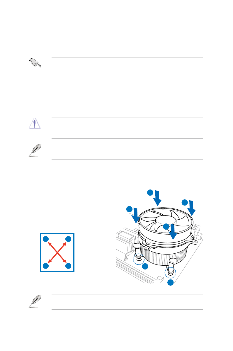
To install the CPU heatsink and fan:
1. Place the heatsink on top of the installed CPU, ensuring that the four
fasteners match the holes on the
motherboard.
2. Push down two fasteners at a time
in a diagonal sequence to secure
the heatsink and fan assembly in
place.
B
A
B
A
A
B
2-12 Chapter 2: Hardware information
B
A
Orient the heatsink and fan assembly such that the CPU fan cable is closest to
the CPU fan connector.
1
1

3. Connect the CPU fan cable to the connector on the motherboard labeled
CPU_FAN.
DO NOT forget to connect the CPU fan connector! Hardware monitoring errors
can occur if you fail to plug this connector.
2.3.3 Uninstalling the CPU heatsink and fan
To uninstall the CPU heatsink and fan:
1. Disconnect the CPU fan cable from
the connector on the motherboard.
2. Rotate each fastener
counterclockwise.
B
A
B
3. Pull up two fasteners at a time in a
diagonal sequence to disengage the
A
heatsink and fan assembly from the
motherboard.
A
B
B
A
4. Carefully remove the heatsink and fan assembly from the motherboard.
ROG Rampage III Extreme 2-13
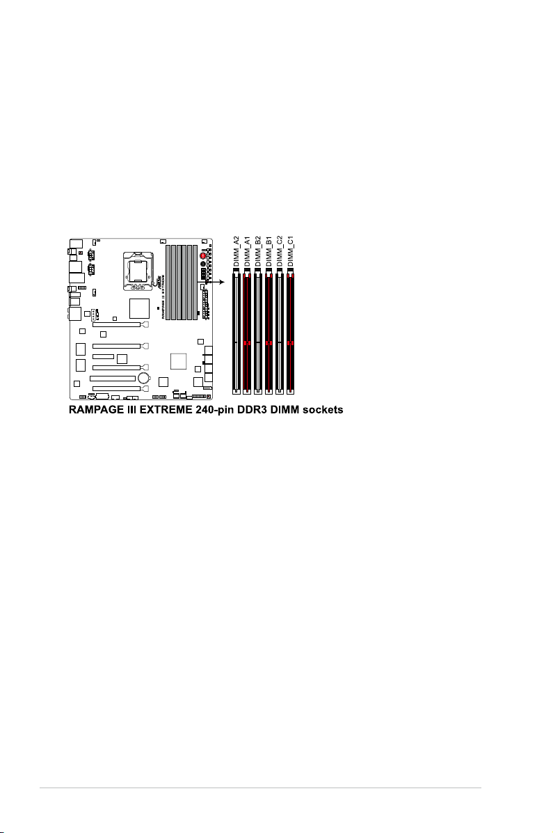
2.4 System memory
2.4.1 Overview
The motherboard comes with six Double Data Rate 3 (DDR3) Dual Inline Memory
Modules (DIMM) sockets.
A DDR3 module has the same physical dimensions as a DDR2 DIMM but is
notched differently to prevent installation on a DDR2 DIMM socket. DDR3 modules
are developed for better performance with less power consumption.
The figure illustrates the location of the DDR3 DIMM sockets:
2-14 Chapter 2: Hardware information

2.4.2 Memory congurations
You may install 512MB, 1GB, 2GB and 4GB unbuffered and non-ECC DDR3
DIMMs into the DIMM sockets.
• You may install varying memory sizes in Channel A, Channel B and
Channel C. The system maps the total size of the lower-sized channel for
the dual-channel or triple-channel configuration. Any excess memory from
the higher-sized channel is then mapped for single-channel operation.
• Due to Intel spec definition, X.M.P. DIMMs and DDR3-1600 are supported
for one DIMM per channel only.
• According to Intel CPU spec, DIMMs with voltage requirement over 1.65V
may damage the CPU permanently. We recommend you install the DIMMs
with the voltage requirement below 1.65V.
• Always install DIMMs with the same CAS latency. For optimum
compatibility, we recommend that you obtain memory modules from the
same vendor.
• Due to the memory address limitation on 32-bit Windows OS, when you
install 4GB or more memory on the motherboard, the actual usable memory
for the OS can be about 3GB or less. For effective use of memory, we
recommend that you do any of the following:
- Use a maximum of 3GB system memory if you are using a 32-bit
Windows OS.
- Install a 64-bit Windows OS when you want to install 4GB or more on the
motherboard.
For more details, refer to the Microsoft® support site at
http://support.microsoft.com/kb/929605/en-us.
• This motherboard does not support DIMMs made up of 512 Mb (64MB)
chips or less (Memory chip capacity counts in Megabit, 8 Megabit/Mb = 1
Megabyte/MB).
• The default memory operation frequency is dependent on its Serial
Presence Detect (SPD), which is the standard way of accessing information
from a memory module. Under the default state, some memory modules
for overclocking may operate at a lower frequency than the vendor-marked
value. To operate at the vendor-marked or at a higher frequency, refer
to section 3.3 Extreme Tweaker menu for manual memory frequency
adjustment.
• For system stability, use a more efficient memory cooling system to support
a full memory load (6 DIMMs) or overclocking condition.
ROG Rampage III Extreme 2-15
Rampage III Extreme Motherboard
Qualied Vendors Lists (QVL) DDR3-2200MH capability3-2200MHz capability-2200MHz capability
Part No. Size SS/DSTiming Voltage DIMM socket support (Optional)
2 DIMM 3 DIMM 4 DIMM 6 DIMM
G.SKILL F3-17600CL8D-4GBPS(XMP) 4GB(2 x 2GB) DS 8-8-8-24 1.65
G.SKILL F3-17600CL9D-4GBTDS(XMP) 4GB(2 x 2GB) DS 9-9-9-24 1.65
KINGMAX FLKE85F-B8KHA(XMP) 4G ( 2x 2G ) DS - 1.5~1.7 •
Rampage III Extreme Motherboard
Qualied Vendors Lists (QVL) DDR3-2133MH capability3-2133MHz capability-2133MHz capability
Part No. Size SS/DSTiming Voltage DIMM socket support (Optional)
2 DIMM 3 DIMM 4 DIMM 6 DIMM
A-DATA AX3U2133XB2G10-EF(XMP) 4GB(2 x 2GB) DS - 2.05~2.15
A-DATA AX3U2133XB2G10-FF(XMP) 6GB(3 x 2GB) DS - 2.05~2.15
A-DATA AD32133F002GMU(XMP) 6GB(3 x 2GB) DS - 2.05~2.15
G.SKILL F3-17066CL8D-4GBPS(XMP) 4GB(2 x 2GB) DS 8-8-8-24 1.65 • • •
G.SKILL F3-17066CL9D-4GBTD(XMP) 4GB(2 x 2GB) DS 9-9-9-24 1.65 • •
G.SKILL F3-17066CL9T-6GB-T 6GB(3 x 2GB) DS 9-9-9-24 1.65 •
GEIL GE34GB2133C9DC(XMP) 4GB(2 x 2GB) DS 9-9-9-28 1.65 •
KINGSTON KHX2133C8D3T1K2/4GX(XMP) 4GB(2 x 2GB) DS 8 1.65 • •
KINGSTON KHX2133C8D3T1K2/4GX(XMP) 4GB(2 x 2GB) DS 8 1.65 •
KINGSTON KHX2133C9D3T1K2/4GX(XMP) 4GB(2 x 2GB) DS 9 1.65 • •
2-16 Chapter 2: Hardware information

Rampage III Extreme Motherboard
Qualied Vendors Lists (QVL) DDR3-2000MH capability3-2000MHz capability-2000MHz capability
Part No. Size SS/DS Timing Voltage DIMM socket support (Optional)
2 DIMM 3 DIMM 4 DIMM 6 DIMM
CORSAIR CMG4GX3M2A2000C8(XMP) 4GB(2 x 2GB) DS 8-8-8-24 1.65 •
Crucial BL12864BE2009.8SFB3(EPP) 1GB SS 9-9-9-28 2 • •
G.SKILL F3-16000CL9D-4GBRH(XMP) 4GB(2 x 2GB) DS 9-9-9-24 1.65 • • •
G.SKILL F3-16000CL9D-4GBTD(XMP) 4GB(2 x 2GB) DS 9-9-9-24 1.65 • • •
G.SKILL F3-16000CL7T-6GBPS(XMP) 6GB(3 x 2GB) DS 7-8-7-20 1.65 • •
G.SKILL F3-16000CL9T-6GBPS(XMP) 6GB(3 x 2GB) DS 9-9-9-24 1.65 • •
GEIL GU34GB2000C9DC(XMP) 4GB(2 x 2GB) DS 9-9-9-28 2 • • • •
GEIL GU34GB2000C9DC(XMP) 4GB(2 x 2GB) DS 9-9-9-28 1.65
GEIL GE38GB2000C9QC(XMP) 8GB(4 x 2GB) DS 9-9-9-28 1.65 • • •
KINGSTON KHX2000C8D3T1K3/3GX(XMP) 3GB(3 x 1GB) SS 8 1.65 • • • •
KINGSTON KHX2000C9D3T1K3/3GX(XMP) 3GB(3 x 1GB) SS 9 1.65 • • • •
KINGSTON KHX2000C8D3T1K3/6GX(XMP) 6GB(3 x 2GB) DS 8 1.65 • • • •
KINGSTON KHX2000C9D3T1FK3/6GX(XMP) 6GB(3 x 2GB) DS 9 1.65 • • • •
KINGSTON KHX2000C9D3T1K3/6GX(XMP) 6GB(3 x 2GB) DS 9 1.65 • • • •
OCZ OCZ3FXT20002GK 2GB(2 x 1GB) SS 8 1.9 • •
OCZ OCZ3P20002GK(EPP) 2GB(2 x 1GB) SS 9 1.9 •
OCZ OCZ3P2000EB2GK 2GB(2 x 1GB) SS 9-8-8 1.8 • • • •
OCZ OCZ3B2000LV6GK 6GB(3 x 2GB) DS 7-8-7 1.65 • •
OCZ OCZ3B2000LV6GK 6GB(3 x 2GB) DS 7-8-7 1.65 • •
Gingle 9CAASS37AZZ01D1 2GB DS 9-9-9-24 - • • •
Patriot PVS32G2000LLKN 2GB(2 x 1GB) SS 9-9-9-24 2
Patriot PVT36G2000LLK(XMP) 6GB(3 x 2GB) DS 8-8-8-24 1.65 • • •
ROG Rampage III Extreme 2-17

Rampage III Extreme Motherboard
Qualied Vendors Lists (QVL) DDR3-18��MH capability3-1866MHz capability-1866MHz capability
Part No. Size SS/DS Timing Voltage DIMM socket support (Optional)
2 DIMM 3 DIMM 4 DIMM 6 DIMM
CORSAIR TR3X6G1866C9DVer4.1(XMP) 6GB(3 x 2GB) DS 9-9-9-24 1.65
G.SKILL F3-15000CL9D-4GBRH (XMP) 4GB(2 x 2GB) DS 9-9-9-24 1.65 • • •
G.SKILL F3-15000CL9D-4GBTD(XMP) 4GB(2 x 2GB) DS 9-9-9-24 1.65 • • •
KINGSTON KHX1866C9D3T1K3/6GX(XMP) 6GB(3 x 2GB) DS 9 1.65 • • • •
OCZ OCZ3RPR1866C9LV3GK 3GB(3 x 1GB) SS 9-9-9 1.65 • • • •
OCZ OCZ3P1866LV4GK 4GB(2 x 2GB) DS 9-9-9 1.65 •
OCZ OCZ3P1866C9LV6GK 6GB(3 x 2GB) DS 9-9-9 1.65 • •
OCZ OCZ3RPR1866C9LV6GK 6GB(3 x 2GB) DS 9-9-9 1.65 •
Super Talent W1866UX2G8(XMP) 2GB(2 x 1GB) SS 8-8-8-24 - • • •
Patriot PVS32G1866LLK(XMP) 2GB(2 x 1GB) SS 8-8-8-24 1.9 •
Patriot PVS32G1866LLK(XMP) 2GB(2 x 1GB) SS 8-8-8-24 1.9 • • •
Team BoxP/N:TXD34096M1866HC7DC-L
(TXD32048M1866HC7-L)(XMP)
4GB(2 x 2GB) DS 7-7-7-21 1.65
• • • •
Rampage III Extreme Motherboard
Qualied Vendors Lists (QVL) DDR3-1800MH capability3-1800MHz capability-1800MHz capability
Part No. Size SS/DS Timing Voltage DIMM socket support (Optional)
2 DIMM 3 DIMM 4 DIMM 6 DIMM
KINGSTON KHX1800C9D3T1K3/6GX(XMP) 6GB(3 x 2GB) DS - 1.65 • • • •
OCZ OCZ3P18002GK 2GB(2 x 1GB) SS 8 - • • • •
OCZ OCZ3P18002GK 2GB(2 x 1GB) SS 8 - • •
OCZ OCZ3P18004GK 4GB(2 x 2GB) DS 8 1.9 • •
Patriot PVS32G1800LLKN(EPP) 2GB(2 x 1GB) SS 8-8-8-20 1.9 • • •
2-18 Chapter 2: Hardware information

Rampage III Extreme Motherboard
Qualied Vendors Lists (QVL) DDR3-1�00MH capability3-1600MHz capability-1600MHz capability
Part No. Size SS/DS Timing Voltage DIMM socket support (Optional)
2 DIMM 3 DIMM 4 DIMM 6 DIMM
A-DATA AD31600G001GMU 1GB SS 9-9-9-24 1.65~1.85 •
A-DATA AX3U1600GB1G9-AG 2GB(2 x 1GB) SS 9-9-9-24 1.65~1.85 •
A-DATA AX3U1600PB1G8-2P 2GB(2 x 1GB) SS 8-8-8-24 1.65-1.85 • • •
A-DATA AD31600E001GMU 3GB(3 x 1GB) SS 8-8-8-24 1.65-1.85 • • •
A-DATA AX3U1600GB1G9-3G 3GB(3 x 1GB) SS 9-9-9-24 1.65~1.85 •
A-DATA AX3U1600PB1G8-3P 3GB(3 x 1GB) SS 8-8-8-24 1.65-1.85 • • •
A-DATA AX3U1600GB2G9-AG(XMP) 4GB(2 x 2GB) DS 9-9-9-24 1.65~1.85 • • • •
A-DATA AX3U1600XB2G7-EF(XMP) 4GB(2 x 2GB) DS 7-7-7-20 1.75-1.85 • • • •
A-DATA AD31600F002GMU(XMP) 6GB(3 x 2GB) DS 7-7-7-20 1.75-1.85 • • • •
A-DATA AX3U1600GB2G9-3G(XMP) 6GB(3 x 2GB) DS 9-9-9-24 1.65~1.85 • • • •
A-DATA AX3U1600GB2G9-3G(XMP) 6GB(3 x 2GB) DS 9-9-9-24 1.65~1.85 • • • •
A-DATA AX3U1600GB2G9-3G 6GB(3 x 2GB) DS 9-9-9-24 1.65~1.85 • • • •
A-DATA AX3U1600XB2G7-FF(XMP) 6GB(3 x 2GB) DS 7-7-7-20 1.75-1.85 • • • •
CORSAIR TR3X3G1600C8D 3GB(3 x 1GB) SS 8-8-8-24 1.65 • •
CORSAIR TR3X3G1600C8DVer2.1(XMP) 3GB(3 x 1GB) SS 8-8-8-24 1.65 • •
CORSAIR TR3X3G1600C9Ver1.1(XMP) 3GB(3 x 1GB) SS 9-9-9-24 1.65 • •
CORSAIR CMD4GX3M2A1600C8(XMP) 4GB(2 x 2GB) DS 8-8-8-24 1.65 • • •
CORSAIR CMG4GX3M2A1600C7(XMP) 4GB(2 x 2GB) DS 7-7-7-20 1.65 • •
CORSAIR CMX4GX3M2A1600C9(XMP) 4GB(2 x 2GB) DS 9-9-9-24 1.65 • • •
CORSAIR TR3X6G1600C8D 6GB(3 x 2GB) DS 8-8-8-24 1.65 • • •
CORSAIR TR3X6G1600C8DVer2.1(XMP) 6GB(3 x 2GB) DS 8-8-8-24 1.65 • • •
CORSAIR TR3X6G1600C9Ver2.1(XMP) 6GB(3 x 2GB) DS 9-9-9-24 1.65 • • •
CORSAIR CMD8GX3M4A1600C8(XMP) 8GB(4 x 2GB) DS 8-8-8-24 1.65 • •
CORSAIR CMX8GX3M4A1600C9(XMP) 8GB(4 x 2GB) DS 9-9-9-24 1.65 • •
Crucial BL12864BA1608.8SFB(XMP) 1GB SS - 1.8 • • • •
Crucial BL25664BN1608.16FF(XMP) 2GB DS 8-8-8-24 1.65 • • • •
G.SKILL F3-12800CL9D-2GBNQ 2GB(2 x 1GB) SS - 1.6 • •
G.SKILL F3-12800CL9D-4GBRL 2GB(2 x 1GB) SS - 1.6 • •
G.SKILL F3-12800CL7D-4GBECO(XMP) 4GB(2 x 2GB) DS 7-8-7-24 - • • • •
G.SKILL F3-12800CL7D-4GBRH(XMP) 4GB(2 x 2GB) DS 7-7-7-24 1.65 • • •
G.SKILL F3-12800CL8D-4GBRM(XMP) 4GB(2 x 2GB) DS 8-8-8-24 1.6 • • • •
G.SKILL F3-12800CL9D-4GBECO(XMP) 4GB(2 x 2GB) DS 9-9-9-24 1.35 • • • •
G.SKILL F3-12800CL8T-6GBPI(XMP) 6GB(3 x 2GB) DS 8-8-8-21 1.6~1.65 • • • •
G.SKILL F3-12800CL9T-6GBNQ 6GB(3 x 2GB) DS 9-9-9-24 1.5-1.6 • • • •
GEIL GV34GB1600C8DC 4GB(2 x 2GB) DS 8-8-8-28 1.6 • • • •
KINGMAX FLGD45F-B8MF7(XMP) 1GB SS - • • •
KINGMAX FLGE85F-B8MF7(XMP) 2GB DS - • • • •
ROG Rampage III Extreme 2-19

KINGSTON KHX1600C9D3K3/12GX(XMP) 12GB(3 x 4GB) DS - 1.65 • • • •
KINGSTON KHX1600C9D3K3/12GX(XMP) 12GB(3 x 4GB) DS 9 1.65 • • • •
KINGSTON KHX1600C8D3K2/4GX(XMP) 4GB(2 x 2GB) DS 8 1.65 • • •
KINGSTON KHX1600C8D3K2/4GX(XMP) 4GB(2 x 2GB) DS 8 1.65 • •
KINGSTON KHX1600C8D3T1K2/4GX(XMP) 4GB(2 x 2GB) DS 8 1.65 • • • •
KINGSTON KHX1600C9D3K2/4G 4GB(2 x 2GB) DS - 1.7~1.9 •
KINGSTON KHX1600C9D3K3/6GX(XMP) 6GB(3 x 2GB) DS 9 1.65 • • • •
OCZ OCZ3P1600EB1G 1GB SS 7-6-6-24 - •
OCZ OCZ3G1600LV3GK 3GB(3 x 1GB) SS 8-8-8 1.65 • • • •
OCZ OCZ3P1600LV3GK 3GB(3 x 1GB) SS 7-7-7 1.65 • • •
OCZ OCZ3OB1600LV4GK 4GB(2 x 2GB) DS 9-9-9 1.65 • • •
OCZ OCZ3P1600EB4GK 4GB(2 x 2GB) DS 7-7-6 1.8 • • • •
OCZ OCZ3P1600LV4GK 4GB(2 x 2GB) DS 7-7-7 1.65
OCZ OCZ3X16004GK(XMP) 4GB(2 x 2GB) DS 7-7-7 1.9 • • •
OCZ OCZ3X1600LV4GK(XMP) 4GB(2 x 2GB) DS 8-8-8 1.65 • • •
OCZ OCZ3FXE1600C7LV6GK 6GB(3 x 2GB) DS 7-7-7 1.65 • •
OCZ OCZ3FXE1600C7LV6GK 6GB(3 x 2GB) DS 7-7-7 1.65
OCZ OCZ3G1600LV6GK 6GB(3 x 2GB) DS 8-8-8 1.65 • • •
OCZ OCZ3G1600LV6GK 6GB(3 x 2GB) DS 8-8-8 1.65 • •
OCZ OCZ3X1600LV6GK(XMP) 6GB(3 x 2GB) DS 8-8-8 1.65 • • • •
OCZ OCZ3X1600LV6GK(XMP) 6GB(3 x 2GB) DS 8-8-8 1.65 • • • •
Super Talent WP160UX4G8(XMP) 4GB(2 x 2GB) DS 8 - • • •
Super Talent WP160UX4G9(XMP) 4GB(2 x 2GB) DS 9 - • • •
Super Talent WB160UX6G8(XMP) 6GB(3 x 2GB) DS - - • • • •
Super Talent WB160UX6G8(XMP) 6GB(3 x 2GB) DS 8 - • • • •
Super Talent WB160UX6G9(XMP) 6GB(3 x 2GB) DS 9 -
Cell Shock CS322271 2GB(2 x 1GB) DS 7-7-7-14 1.7-1.9 • • • •
EK Memory EKM324L28BP8-I16(XMP) 4GB(2 x 2GB) DS 9 - • • •
Elixir M2Y2G64CB8HA9N-DG(XMP) 2GB DS - - • • • •
Mushkin 996657 4GB(2 x 2GB) DS 7-7-7-20 - • • • •
Mushkin 998659(XMP) 6GB(3 x 2GB) DS 9-9-9-24 1.5-1.6 • • • •
Patriot PVT33G1600ELK 3GB(3 x 1GB) SS 9-9-9-24 1.65 • • •
PATRIOT PGS34G1600LLKA 4GB(2 x 2GB) DS 7-7-7-20 1.7 • • • •
Patriot PVS34G1600ELK 4GB(2 x 2GB) DS 9-9-9-24 1.8 • •
Patriot PVS34G1600LLK(XMP) 4GB(2 x 2GB) DS 7-7-7-20 1.9 •
Patriot PVS34G1600LLKN 4GB(2 x 2GB) DS 7-7-7-20 2.0 • •
Patriot PVT36G1600ELK 6GB(3 x 2GB) DS 9-9-9-24 1.65 • • • •
Patriot PVT36G1600ELK 6GB(3 x 2GB) DS 9-9-9-24 1.65 • •
Patriot PVT36G1600LLK(XMP) 6GB(3 x 2GB) DS 8-8-8-24 1.65 • •
Team BoxP/N:
TXD34096M1600HC6DC-L
(TXD32048M1600HC6-L)(XMP)
4GB(2 x 2GB) DS 6-7-6-18 1.65 • • •
2-20 Chapter 2: Hardware information

Rampage III Extreme Motherboard
Qualied Vendors Lists (QVL) DDR3-1333MH capability3-1333MHz capability-1333MHz capability
Part No. Size SS/DSChip
A-DATA AD3133301GOU 1GB SS A-DATA AD30908C8D-15IG - - • • •
A-DATA AD31333002GOU 2GB DS A-DATA AD30908C8D-15IG - - • • •
A-DATA AD3U1333B2G9-2 2GB DS A-DATA AD30908C8D-15IG - - • • •
A-DATA AX3U1333PB2G7-2P 4GB(2 x 2GB) DS - - 7-7-7-20 1.65-1.85 • • • •
A-DATA AD3U1333C4G9-B 4GB DS Hynix H5TQ2G83AFRH9C 1333-9-9-9-24 - • • • •
A-DATA AD31333E002G0U 6GB(3 x 2GB) DS - - 7-7-7-20 1.65-1.85 • • • •
A-DATA AX3U1333PB2G7-3P 6GB(3 x 2GB) DS - - 7-7-7-20 1.65-1.85 • • • •
Apacer 78.A1GC6.9L1 2GB DS Apacer AM5D5808DEWSBG 9 - • • • •
CORSAIR TR3X3G1333C9 (Ver2.1) 3GB(3 x 1GB) SS - - 9-9-9-24 1.5 • • • •
CORSAIR CM3X1024-1333C9DHX 1GB DS - - - 1.1 •
CORSAIR BoxP/N:TWIN3X2048-1333C9
(CM3X1024-1333C9)Ver1.1
CORSAIR CM3X2G1333C9 2GB DS - - 9-9-9-24 1.5 • • • •
CORSAIR BoxP/N:TW3X4G1333C9DHX
(CM3X2048-1333C9DHX)Ver3.2
CORSAIR TR3X6G1333C9 (Ver2.1) 6GB(3 x 2GB) DS - - 9-9-9-24 1.5 • • •
CORSAIR CMX8GX3M4A1333C9 8GB(4 x 2GB) DS - - 9-9-9-24 1.5 • • • •
Crucial CT12864BA1339.8FF 1GB SS MICRON D9KPT 9 - • • • •
Crucial CT12864BA1339.8SFD 1GB SS MICRON MT8JF12864AY-1G4D1 - - • • •
Crucial CT12872BA1339.9FF 1GB SS MICRON D9KPT(ECC) 9 - • • • •
Crucial BL25664BN1337.16FF(XMP) 2GB DS - - 7-7-7-24 1.65 • • • •
Crucial CT25664BA1339.16FF 2GB DS MICRON D9KPT 9 - • • • •
Crucial CT25664BA1339.16SFD 2GB DS MICRON D9JNM - - • • •
Crucial CT25672BA1339.18FF 2GB DS MICRON D9KPT(ECC) 9 - • • • •
Crucial BL25664BA1336.16SFB1 4GB(2 x 2GB) DS NA - 6-6-6-20 1.8 • • • •
ELPIDA EBJ10UE8BAW0-DJ-E 1GB SS ELPIDA J1108BABG-DJ-E 9 - • • • •
ELPIDA EBJ10UE8BDF0-DJ-F 1GB SS ELPIDA J1108BDSE-DJ-F - - • • •
ELPIDA EBJ10UE8EDF0-DJ-F 1GB SS ELPIDA J1108EDSE-DJ-F - - • • • •
ELPIDA EBJ21UE8BAW0-DJ-E 2GB DS ELPIDA J1108BABG-DJ-E 9 - • • • •
ELPIDA EBJ21UE8BDF0-DJ-F 2GB DS ELPIDA J1108BDSE-DJ-F - - • • •
ELPIDA EBJ21UE8EDF0-DJ-F 2GB DS ELPIDA J1108EDSE-DJ-F - - • • • •
G.SKILL F3-10600CL7D-2GBPI 2GB(2 x 1GB) SS - - - 1.65 • •
G.SKILL F3-10600CL8D-2GBHK 2GB(2 x 1GB) SS - - - 1.65 • • • •
G.SKILL F3-10666CL7T-6GBPK(XMP) 2GB DS - - 7-7-7-18 1.5-1.6 • • • •
G.SKILL F3-10666CL7D-4GBPI(XMP) 4GB(2 x 2GB) DS - - 7-7-7-21 1.5 • • •
G.SKILL F3-10666CL7D-4GBRH(XMP) 4GB(2 x 2GB) DS - - 7-7-7-21 1.5 • • •
G.SKILL F3-10666CL8D-4GBECO(XMP) 4GB(2 x 2GB) DS - - 8-8-8-24 1.35 • • • •
G.SKILL F3-10666CL8D-4GBHK(XMP) 4GB(2 x 2GB) DS - - 8-8-8-21 1.5-1.6 • • • •
G.SKILL F3-10666CL8D-4GBRM(XMP) 4GB(2 x 2GB) DS - - 8-8-8-21 1.5-1.6 • • • •
2GB(2 x 1GB) DS - - 9-9-9-24 1.70 • • • •
4GB(2 x 2GB) DS - - 9-9-9-24 1.70 •
Chip NO. Timing Voltage DIMM socket
Brand
support
(Optional)
2 3 4 6
ROG Rampage III Extreme 2-21

G.SKILL F3-10666CL9T-6GBNQ 6GB(3 x 2GB) DS - - 9-9-9-24 1.5 • • • •
GEIL GG34GB1333C9DC 4GB(2 x 2GB) DS GEIL GL1L128M88BA12N 9-9-9-24 1.3 • • • •
GEIL GV34GB1333C7DC 4GB(2 x 2GB) DS - - 7-7-7-24 1.5 • • • •
Hynix HMT112U6BFR8C-H9 1GB SS Hynix H5TQ1G83BFR 9 - • • • •
Hynix HMT125U6BFR8C-H9 2GB DS Hynix H5TQ1G83BFR 9 - • • • •
Hynix HMT125U6BFR8C-H9 2GB DS Hynix H5TQ1G83BFRH9C 9 - • • • •
KINGMAX FLFD45F-B8KG9 1GB SS KingMax KFB8FNGBF-ANX-15A - • • • •
KINGMAX FLFE85F-B8KG9 2GB DS KingMax KFB8FNGBF-ANX-15A -
KINGSTON KVR1333D3N9/1G 1G SS Kingston D1288JELDPGD9U - 1.5 • • • •
KINGSTON KVR1333D3N9/2G 2GB DS Qimonda IDSH1G-03A1F1C-13H 9 1.5 • • • •
KINGSTON KVR1333D3E9S/4G 4GB DS SAMSUNG K4B2G0846B-HCH9 - 1.5 • • • •
KINGSTON KVR1333D3N9/4G 4GB DS SAMSUNG K4B2G0846B-HCH9 9 1.5
MICRON MT8JTF12864AZ-1G4F1 1GB SS MICRON 9FF22 D9KPT 9 - • • • •
MICRON MT8JTF12864AZ-1G4F1 1GB SS MICRON D9KPT 9 - • • • •
MICRON MT9JSF12872AZ-1G4F1 1GB SS MICRON D9KPT(ECC) 9 - • • • •
MICRON MT16JF25664AZ-1G4F1 2GB DS MICRON D9KPT 9 - • • • •
MICRON MT16JTF25664AZ-1G4F1 2GB DS MICRON 9FF22 D9KPT 9 - • • • •
MICRON MT18JSF25672AZ-1G4F1 2GB DS MICRON D9KPT(ECC) 9 - • • • •
OCZ OCZ3RPX1333EB2GK 1GB SS - - - - • •
OCZ OCZ3RPX1333EB2GK 2GB(2 x 1GB) SS NANYA - 6-5-5 1.85 •
OCZ OCZ3G1333LV3GK 3GB(3 x 1GB) SS - - 9-9-9 1.65 • •
OCZ OCZ3P1333LV3GK 3GB(3 x 1GB) SS - - 7-7-7 1.65 • • • •
OCZ OCZ3P13332GK 1GB DS - - 7-7-7-20 - •
OCZ OCZ3G13334GK 4GB(2 x 2GB) DS - - 9 1.7 •
OCZ OCZ3G1333ULV4GK 4GB(2 x 2GB) DS - - 8-8-8 1.65 •
OCZ OCZ3P13334GK 4GB(2 x 2GB) DS - - 7 1.8 • • • •
OCZ OCZ3P1333LV4GK 4GB(2 x 2GB) DS - - 7-7-7 1.65 • •
OCZ OCZ3RPX1333EB4GK 4GB(2 x 2GB) DS - - - 1.85 • •
OCZ OCZ3G1333LV6GK 6GB(3 x 2GB) DS - - 9-9-9 1.65 • • •
OCZ OCZ3P1333LV6GK 6GB(3 x 2GB) DS - - 7-7-7 1.65 • • •
OCZ OCZX1333LV6GK(XMP) 6GB(3 x 2GB) DS NA - 8-8-8 1.6 • • • •
PSC AL7F8G73D-DG1 1GB SS PSC A3P1GF3DGF - - • • • •
PSC AL8F8G73D-DG1 2GB DS PSC A3P1GF3DGF - - • • • •
SAMSUNG M378B2873DZ1-CH9 1GB SS SAMSUNG K4B1G0846D 9 - • • • •
SAMSUNG M378B2873EH1-CH9 1GB SS SAMSUNG K4B1G0846E - - • • • •
SAMSUNG M391B2873DZ1-CH9 1GB SS SAMSUNG K4B1G0846D(ECC) 9 - • • • •
SAMSUNG M378B5673DZ1-CH9 2GB DS SAMSUNG K4B1G0846D 9 - • • • •
SAMSUNG M378B5673EH1-CH9 2GB DS SAMSUNG K4B1G0846E - - • • •
SAMSUNG M391B5673DZ1-CH9 2GB DS SAMSUNG K4B1G0846D(ECC) 9 - • • • •
SAMSUNG M378B5273BH1-CH9 4GB DS SAMSUNG K4B2G0846B-HCH9 9 - • • • •
Super
W1333UX2G8(XMP) 2GB(2 x 1GB) SS - - 8 1.8 • • • •
Talent
Asint SLY3128M8-EDJ 1GB SS Asint DDRIII1208-DJ - - • • • •
2-22 Chapter 2: Hardware information

Asint SLY3128M8-EDJE 1GB SS ELPIDA J1108BASE-DJ-E - - • •
Asint SLZ3128M8-EDJ 2GB DS Asint DDRIII1208-DJ - - • • • •
Asint SLZ3128M8-EDJE 2GB DS ELPIDA J1108BASE-DJ-E - - • • • •
ASUS N/A 1GB DS - - - - • • • •
ATP AQ28M64A8BJH9S 1GB SS SAMSUNG K4B1G0846E - - • • • •
ATP AQ28M72D8BJH9S 1GB SS SAMSUNG K4B1G0846D(ECC) - - • • • •
ATP AQ56M64B8BJH9S 2GB DS SAMSUNG K4B1G0846D - - • • • •
ATP AQ56M72E8BJH9S 2GB DS SAMSUNG K4B1G0846D(ECC) - - • • • •
BUFFALO FSX1333D3G-1G 1GB SS - - - - • • • •
BUFFALO FSH1333D3G-T3G(XMP) 3GB(3 x 1GB) SS - - 7-7-7-20 - • • • •
BUFFALO FSX1333D3G-2G 2GB DS - - - - • • •
EK Memory EKM324L28BP8-I13 4GB(2 x 2GB) DS - - 9 - •
Elixir M2Y2G64CB8HA9N-CG 2GB DS - - - - • • •
Elixir M2Y2G64CB8HC9N-CG 2GB DS - - - - • • • •
Patriot PDC32G1333LLK 1GB SS PATRIOT - 7 1.7 •
Patriot PVT33G1333ELK 3GB(3 x 1GB) SS - - 9-9-9-24 1.65 • • • •
Patriot PVS34G1333ELK 4GB(2 x 2GB) DS - - 9-9-9-24 1.5 •
Patriot PVS34G1333LLK 4GB(2 x 2GB) DS - - 7-7-7-20 1.7 •
Patriot PVT36G1333ELK 6GB(3 x 2GB) DS - - 9-9-9-24 1.65 • • • •
Silicon
SP001GBLTU1333S01 1GB SS NANYA NT5CB128M8AN-CG - - • • • •
Power
Silicon
SP001GBLTU133S02 1GB SS S-POWER I0YT3E0 9 - • • • •
Power
Silicon
SP002GBLTU133S02 2GB DS S-POWER I0YT3E0 9 - • • •
Power
UMAX E41302GP0-73BDB 2GB DS UMAX U2S24D30TP-13 - • • • •
6 DIMM Slots:
• 2 DIMMs: Supports two (2) modules inserted into slot A1 and B1 as one
pair of Dual-channel memory configuration.
• 3 DIMMs: Supports three (3) modules inserted into the orange slots (A1, B1
and C1) as one set of Triple-channel memory configuration
• 4 DIMMs: Supports four (4) modules inserted into the orange slots (A1,
B1 and C1) and the black slot A2 as one set of Triple-channel memory
configuration.
• 6 DIMMs: Supports six (6) modules inserted into both the orange slots and
the black slots as two set of Triple-channel memory configuration.
ROG Rampage III Extreme 2-23

2.4.3 Installing a DIMM
Ensure to unplug the power supply before adding or removing DIMMs or other
system components. Failure to do so may cause severe damage to both the
motherboard and the components.
1. Unlock a DIMM socket by pressing
the retaining clip outward.
2. Align a DIMM on the socket
such that the notch on the DIMM
matches the DIMM slot key on the
socket.
A DIMM is keyed with a notch so that it fits in only one direction. DO NOT force
a DIMM into a socket in the wrong direction to avoid damaging the DIMM.
3. Hold the DIMM by both of its
ends, then insert the DIMM
vertically into the socket. Apply
force to both ends of the DIMM
simultaneously until the retaining
clip snaps back into place, and
the DIMM cannot be pushed
in any further to ensure proper
sitting of the DIMM.
Always insert the DIMM into the socket VERTICALLY to prevent DIMM notch
damage.
DIMM notch
DIMM slot key
1
2
Unlocked retaining clip
3
Locked Retaining Clip
2.4.4 Removing a DIMM
1. Press the retaining clip outward to
unlock the DIMM.
2. Remove the DIMM from the
socket.
2-24 Chapter 2: Hardware information
2
1

2.5 Expansion slots
In the future, you may need to install expansion cards. The following sub-sections
describe the slots and the expansion cards that they support.
Ensure to unplug the power cord before adding or removing expansion cards.
Failure to do so may cause you physical injury and damage motherboard
components.
2.5.1 Installing an expansion card
To install an expansion card:
1. Before installing the expansion card, read the documentation that came with
it and make the necessary hardware settings for the card.
2. Remove the system unit cover (if your motherboard is already installed in a
chassis).
3. Remove the bracket opposite the slot that you intend to use. Keep the screw
for later use.
4. Align the card connector with the slot and press firmly until the card is
completely seated on the slot.
5. Secure the card to the chassis with the screw you removed earlier.
6. Replace the system cover.
2.5.2 Conguring an expansion card
After installing the expansion card, configure it by adjusting the software settings.
1. Turn on the system and change the necessary BIOS settings, if any. See
Chapter 3 for information on BIOS setup.
2. Assign an IRQ to the card. Refer to the tables on the next page.
3. Install the software drivers for the expansion card.
When using PCI cards on shared slots, ensure that the drivers support “Share
IRQ” or that the cards do not need IRQ assignments. Otherwise, conflicts will
arise between the two PCI groups, making the system unstable and the card
inoperable. Refer to the table on the next page for details.
ROG Rampage III Extreme 2-25

2.5.3 Interrupt assignments
Standard interrupt assignments
IRQ Priority Standard function
0 1 System Timer
1 2 Keyboard Controller
2 – Redirect to IRQ#9
4 12 Communications Port (COM1)*
5 13 IRQ Holder for PCI Steering*
6 14 Reserved
7 15 Reserved
8 3 System CMOS/Real Time Clock
9 4 IRQ Holder for PCI Steering*
10 5 IRQ Holder for PCI Steering*
11 6 IRQ Holder for PCI Steering*
12 7 Reserved
13 8 Numeric Data Processor
14 9 Primary IDE Channel
* These IRQs are usually available for PCI devices.
IRQ assignments for this motherboard
A B C D E F G H
PCIEX16/X8_1 shared – – – – – – –
PCIEX8_2 shared – – – – – – –
PCIEX16/X8_3 shared – – – – – – –
PCIEX8_4 shared – – – – – – –
PCIEX4_1 shared – – – – – – –
USB 1.0#1 – – – – – – – shared
USB 1.0#2 – – – shared – – – –
USB 1.0#3 – – shared – – – – –
USB 1.0#4 shared – – – – – – –
USB 1.0#5 – – – – – shared – –
USB 1.0#6 shared – – – – – – –
USB 1.0#7 – – – shared – – – –
USB 2.0#1 – – – – – – – shared
USB 2.0#2 – – shared – – – – –
SATA_1 – – shared – – – – –
SATA_2 – – – – shared – – –
MVL9128 shared – – – – – – –
JMB36X shared – – – – – – –
HD Audio – – – – – shared –
IEEE 1394 – – shared – – – – –
PCI1 shared – – – – – – –
2-26 Chapter 2: Hardware information

2.5.4 PCI slot
The PCI slot supports cards such as a LAN card, SCSI card, USB card, and other
cards that comply with PCI specifications. Refer to the figure below for the location
of the slot.
2.5.5 PCI Express x4 slot
This motherboard has one PCI Express x4 slot that supports a PCI Express x4
card complying with the PCI Express specifications. Refer to the figure below for
the location of the slot.
2.5.6 PCI Express x16 slots
This motherboard has four PCI Express x16 slots that support PCI Express x16
cards complying with the PCI Express specifications. Refer to the figure below for
the location of the slot.
PCI Express x16_4 slot
PCI Express x16_3 slot
PCI Express x4_1 slot
PCI Express x16_2 slot
PCI Express x16_1 slot
ROG Rampage III Extreme 2-27
PCI slot

• Refer to the following configuration table for installation.
PCIex16 Slot # Single
VGA
1 x16 x16 x16 x8
2 — — — x8
3 — x16 x8 x8
4 — — x8 x8
• We recommend that you provide sufficient power when running
CrossFireX™ or SLI mode. See page 2-46 for details.
• Connect a chassis fan to the motherboard connector labeled
CHA_FAN1/2/3 when using multiple graphics cards for better thermal
environment.
SLI/CF 3 way
SLI/CFX
Quad CFX
2-28 Chapter 2: Hardware information

2.6 Jumper
1. Clear RTC RAM (3-pin CLRTC_SW)
This jumper allows you to enable the clr CMOS switch on the back I/O. You
can clear the CMOS memory and system setup parameters by erasing the
CMOS RTC RAM data. The clr CMOS switch on the back I/O helps you
easily clear the system setup information such as system passwords.
To erase the RTC RAM:
1. Press down the clr CMOS switch on the back I/O.
2. Hold down the <Del> key during the boot process and enter BIOS setup
to re-enter data.
clr CMOS switch behavior
System power state G3* S5* S0 (DOS mode) S0 (OS mode) S1 S3 S4
Clearing CMOS **
*G3: Power off without +5VSB power (AC power loss); S5: Power off with +5VSB power
**The system shuts dowm immediately.
• The clr CMOS switch will not function if the CLRTC_SW jumper is moved to
the Disable position.
• Ensure to re-enter your previous BIOS settings after you clear the CMOS.
• You do not need to clear the RTC when the system hangs due to CPU
overclocking. With the C.P.R. (CPU Parameter Recall) feature, shut down
and reboot the system so the BIOS can automatically reset CPU parameter
settings to default values.
ROG Rampage III Extreme 2-29
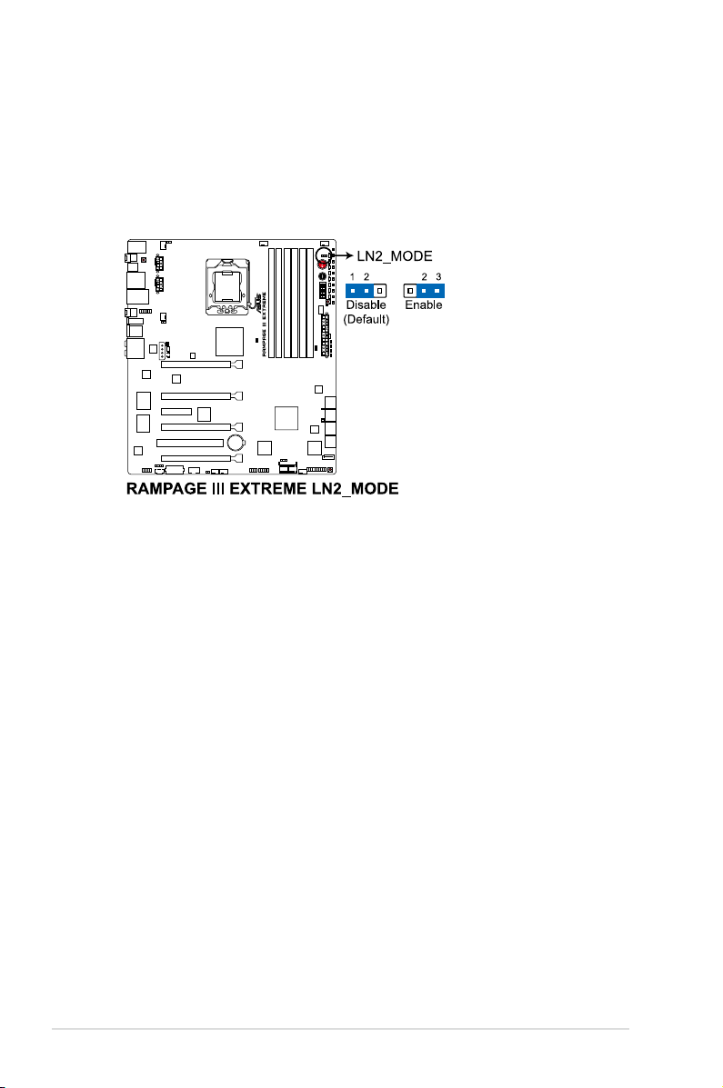
2. LN2 Mode jumper (3-pin LN2)
With LN2 mode activated, the ROG motherboard is optimized to remedy the
cold-boot bug during POST at an extremely low temperature and help the
system boot successfully.
2-30 Chapter 2: Hardware information

2.7 RC Bluetooth card
RC Bluetooth card layout
3
1
1. Antenna: Receives the Bluetooth signal. The plastic cap on the antenna
protects it from possible damage.
2. Bluetooth Switch: Toggles the RC Bluetooth function ON and OFF. When
the RC Bluetooth is OFF, the normal Bluetooth connection is still available.
3. Bluetooth Connector: Connects the RC_BLUETOOTH connector on the
motherboard.
2
RC Bluetooth card installation
1. Locate the RC_Bluetooth
connector on the
motherboard.
2. Orient the RC_Bluetooth
card and firmly install it to
the connector.
The photos above are for reference only, the actual motherboard layout may
differ by models.
ROG Rampage III Extreme 2-31

2.8 I/O shield Installation
1. Install the I/O shield to the chassis by snapping it in place from inside.
2. Orient the motherboard and install it to the chassis. Ensure that the
motherboard external ports fit the I/O openings.
Be cautious when installing the motherboard. The I/O shield edge springs may
damage the I/O ports.
The photos above are for reference only, the actual I/O shield may differ by
models.
2-32 Chapter 2: Hardware information

2.9 Connectors
2.9.1 Rear panel connectors
Rear panel connectors
1. PS/2 keyboard port (purple) 8. Optical S/PDIF Out port
2. USB 2.0 ports 5 and 6 9. IEEE 1394a port
3. LAN (RJ-45) port* 10. External SATA port
4. RC Bluetooth switch 11. USB 2.0 ports 1 and 2
5. USB 3.0 ports 1 and 2 12. ROG Connect switch
6. USB 2.0 ports 3 and 4
7. Clear CMOS switch 14. Audio ports
13. USB 2.0 port 14/
ROG Connect port
To use hot-plug, set the Controller Mode in the BIOS settings to [AHCI] mode.
See section 3.5.3 Onboard Devices Conguration for details.
ROG Rampage III Extreme 2-33

* LAN port LED indications
Speed
Activity/Link
OFF OFF Soft-off Mode
Yellow Blinking OFF During Power ON/OFF
Yellow Blinking ORANGE 100 Mbps connection
Yellow Blinking GREEN 1 Gbps connection
Speed LED
Description
Activity/
Link LED
LAN port
LED
2.9.2 ROG Connect switch and RC Bluetooth switch
ROG Connect switch
The ROG Connect function allows you to monitor and control remotely with the
other computer through the provided ROG Connect cable.This switch also features
USB BIOS FlashBack, which enables you to flash the BIOS in standby power.
To use ROG Connect:
1. Connect one end of the ROG Connect cable to the ROG Connect port and
the other to your notebook or netbook.
2. Press the switch to start to connection.
To use USB BIOS FlashBack:
1. Download the latest BIOS from ASUS support website. Rename it R3E.ROM,
save it to a USB flash drive and place it in the root directory.
2. Connect the USB flash drive to the ROG Connect port.
3. Press and hold the ROG Connect switch until it starts blinking (with standby
power).
4. When the blinking stops, the BIOS flash completes.
Refer to the Appendix for the qualified vendor list for the USB flash disk before
using the USB BIOS Flashback function.
2-34 Chapter 2: Hardware information

RC Bluetooth switch
The RC Bluetooth function allows you to control your system wirelessly through
your mobile smartphone.
To use RC Bluetooth
1. Install the application from the motherboard support DVD to your mobile
phone.
2. Ensure that the Bluetooth function of your mobile phone is activated.
3. Press the RC Bluetooth switch.
4. Search the available Bluetooth-enabled devices nearby and add RC_
Bluetooth.
5. Pair your mobile phone and the system and start using RC Bluetooth
function.
• Refer to the Appendix for the qualified vendor list for the mobile phone
before using the RC Bluetooth function.
• The RC Bluetooth is designed for the following mobile phone operating
systems. Visit the ASUS website at www.asus.com for the latest supported
operating system list.
Mobile phone OS Version
Windows Mobile 6.5/ 6.1/ 6.0 Professional (at display resolution 480*800)
Symbian S60 3rd edition, feature pack 2/ feature pack 1
Android Google Android 2.0 or later version
• For mobile phone with Symbian OS, RC Bluetooth supports keypad control
only. RC Bluetooth is not available for phones with touch screen control.
• For mobile phone with Windows Mobile OS, you need to click the COM
Port tab and add RC_Bluetooth.
• The default pairing code for RC Bluetooth is 0000.
• When you use RC Bluetooth, we recommend you stop running applications,
including ASUS PC Probe II and Ai Suite.
ROG Rampage III Extreme 2-35
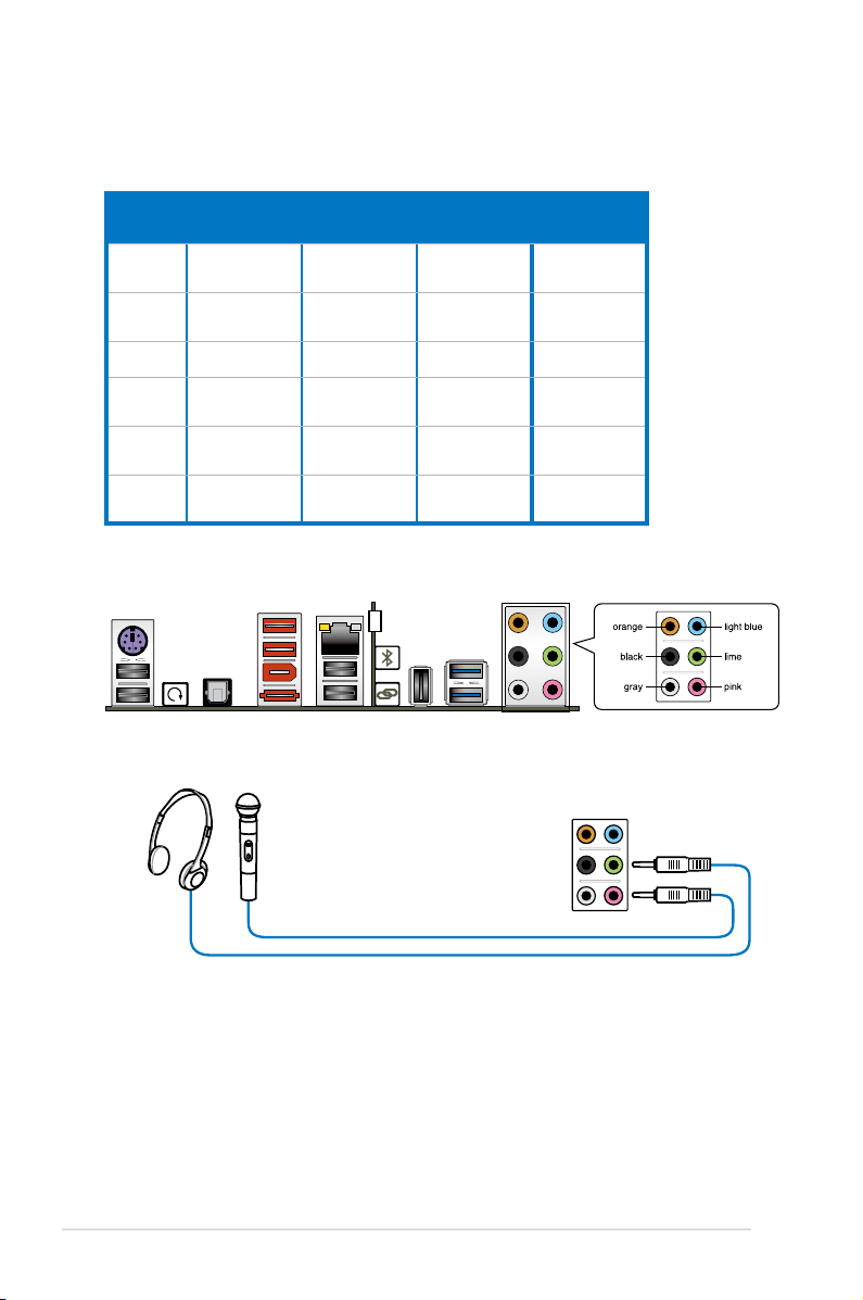
2.9.3 Audio I/O connections
Audio 2, 4, �, or 8-channel conguration
Port
Light
Blue
Lime Line Out
Pink Mic In Mic In Mic In Mic In
Orange – –
Black –
Gray – – –
Headset
2-channel
Line In Line In Line In Line In
4-channel 6-channel 8-channel
Front Speaker
Out
Rear Speaker
Out
Front Speaker
Out
Center/
Subwoofer
Rear Speaker
Out
Front Speaker
Rear Speaker
Side Speaker
Audio I/O ports
Connect to Headphone and Mic
Out
Center/
Subwoofer
Out
Out
2-36 Chapter 2: Hardware information

Connect to Stereo / 2.1-channel Speakers
Connect to 4.1-channel Speakers
Connect to 5.1-channel Speakers
ROG Rampage III Extreme 2-37

Connect to 7.1-channel Speakers
2-38 Chapter 2: Hardware information

2.9.4 Internal connectors
1. ICH10R Serial ATA connectors (7-pin SATA 1-6 [grey])ICH10R Serial ATA connectors (7-pin SATA 1-6 [grey])
These connectors are for the Serial ATA signal cables for Serial ATA hard disk
drives and optical disc drives.
If you installed Serial ATA hard disk drives, you can create a RAID 0, 1, 5,
and 10 configuration with the Intel® Matrix Storage Technology through the
onboard Intel® ICH10R RAID controllers.
•
These connectors are set to Standard IDE mode by default. In Standard
IDE mode, you can connect Serial ATA boot/data hard disk drives to these
connectors. If you intend to create a Serial ATA RAID set using these
connectors, set the Congure SATA as item in the BIOS to [RAID]. See
section 3.4.5 Storage Conguration for details.
• Before creating a RAID set, refer to section 4.4 RAID congurations or the
manual bundled in the motherboard support DVD.
•
You must install Windows® XP Service Pack 2 or later versions before using
Serial ATA hard disk drives. The Serial ATA RAID feature is available only if
you are using Windows® XP SP2 or later versions.
•
When using hot-plug and NCQ, set the Congure SATA as in the BIOS to
[AHCI]. See section 3.4.5 Storage Conguration for details.
ROG Rampage III Extreme 2-39

2. Marvell® Serial ATA 6.0 Gb/s connectors (7-pin SATA_6G_1/2 [red])
These connectors connect to Serial ATA 6.0 Gb/s hard disk drives via Serial
ATA 6.0 Gb/s signal cables.
•
These connectors are set to Standard IDE mode by default. In Standard
IDE mode, you can connect Serial ATA data hard disk drives to these
connectors.
•
You must install Windows® XP Service Pack 2 or later versions before using
Serial ATA hard disk drives.
•
When using hot-plug and NCQ, set the Marvell Controller item in the BIOS
to [AHCI Mode]. Refer to section 3.5.3 Onboard Devices Conguration for
details.
3. JMicron® JMB363 Serial ATA connector (7-pin SATA_E1 [black])
This connector connects to a Serial ATA hard disk drive or optical disc drive via
a Serial ATA signal cable.
2-40 Chapter 2: Hardware information

4. USB connector (10-1 pin USB78)
This connector is for a USB 2.0 port. Connect the USB module cable to
this connector, then install the module to a slot opening at the back of the
system chassis. This USB connector complies with USB 2.0 specification that
supports up to 480 Mbps connection speed.
Never connect a 1394 cable to the USB connectors. Doing so will damage the
motherboard!
You can connect the USB cable to ASUS Q-Connector (USB, blue) first, and
then install the Q-Connector (USB) to the USB connector onboard.
5. ROG connector (3-pin ROG)
This connector is for the box (labeled as Republic of Gamers) on the
heatpipe assembly. Connect the cable of the box and it lights when the
system is on.
ROG Rampage III Extreme 2-41

6. OC station connector (8-pin OC_Station)
This connector is for ASUS OC Station connection only. Connect one endConnect one end
of the supplied data cable to the GP connector on the OC Station and the
other end to this connector and USB78 on the motherboard to enjoy easier
overclocking.
7. IEEE 1394a port connector (10-1 pin IE1394_2)
This connector is for an IEEE 1394a port. Connect the IEEE 1394a module
cable to this connector, then install the module to a slot opening at the back
of the system chassis.
Never connect a USB cable to the IEEE 1394a connector. Doing so will damage
the motherboard!
The IEEE 1394a module is purchased separately.
2-42 Chapter 2: Hardware information

8. CPU, chassis, and optional fan connectors
(4-pin CPU_FAN, 4-pin PWR_FAN, 4-pin CHA_FAN1–3, 4-pin OPT_FAN1–3)
The fan connectors support cooling fans of 350 mA–2000 mA (24 W max.)
or a total of 1 A–7 A (84 W max.) at +12V. Connect the fan cables to the fan
connectors on the motherboard, ensuring that the black wire of each cable
matches the ground pin of the connector.
DO NOT forget to connect the fan cables to the fan connectors. Insufficient air
flow inside the system may damage the motherboard components. These are
not jumpers! DO NOT place jumper caps on the fan connectors!
If you install two VGA cards, we recommend that you plug the chassis fan
cable to the motherboard connector labeled OPT_FAN1/2/3 for better thermal
environment.
9. Option Fan-Thermal module connector (2-pin FAN1)
This connector is for the supplied Fan-Thermal Module.
ROG Rampage III Extreme 2-43

10. Thermal sensor cable connectors (2-pin OPT_TEMP1/2/3)
These connectors are for temperature monitoring. Connect the thermal
sensor cables to these connectors and place the other ends to the devices
which you want to monitor temperature. The optional fan1/2/3 can work with
the temperature sensors for a better cooling effect.
Enable OPT FAN1/2/3 overheat protection in BIOS if you connect thermal
sensor cables to these connectors.
11. Optical drive audio connector (4-pin CD)
These connectors allow you to receive stereo audio input from sound sources
such as a CD-ROM, TV tuner, or MPEG card.
2-44 Chapter 2: Hardware information

12. Digital audio connector (4-1 pin SPDIF_OUT)
This connector is for an additional Sony/Philips Digital Interface (S/PDIF)
port(s). Connect the S/PDIF Out module cable to this connector, then install
the module to a slot opening at the back of the system chassis.
The S/PDIF module is purchased separately.
13. Front panel audio connector (10-1 pin AAFP)
This connector is for a chassis-mounted front panel audio I/O module that
supports either HD Audio or legacy AC`97 audio standard. Connect one end
of the front panel audio I/O module cable to this connector.
• We recommend that you connect a high-definition front pane l audio
module to this connector to avail of the motherboard’s high-definition audio
capability.
• If you want to connect a high-definition front panel audio module to thisIf you want to connect a high-definition front panel audio module to this
connector, set the
if you want to connect an AC'97 front panel audio module to this connector,
set the item to
ROG Rampage III Extreme 2-45
Front Panel Type
[AC97]
. By default, this connector is set to
item in the BIOS setup to
[HD Audio];
[HD Audio]
.

14. ATX power connectors
(24-pin EATXPWR, 8-pin EATX12V_1/2, 4-pin EZ_PLUG_1/2)
These connectors are for ATX power supply plugs. The power supply plugs
are designed to fit these connectors in only one orientation. Find the proper
orientation and push down firmly until the connectors completely fit.
• For a fully configured system, we recommend that you use a power supply
unit (PSU) that complies with ATX 12 V Specification 2.0 (or later version)
and provides a minimum power of 600 W.
• Do not forget to connect the 8-pin EATX12V power plugs; otherwise, the
system will not boot.
• Connect the 4-pin EZ_PLUG_1 and EZ_PLUG_2 power plugs to ensure
sufficient power supply when you install multiple graphics cards.
• Use of a PSU with a higher power output is recommended when
configuring a system with more power-consuming devices. The system
may become unstable or may not boot up if the power is inadequate. Refer
to the Appendix for the certified 500W power supply or above.
• If you are uncertain about the minimum power supply requirement for your
system, refer to the Recommended Power Supply Wattage Calculator
at http://support.asus.com/PowerSupplyCalculator/PSCalculator.
aspx?SLanguage=en-us for details.
2-46 Chapter 2: Hardware information

15. System panel connector (20-8 pin PANEL)
This connector supports several chassis-mounted functions.
•
System power LED (2-pin PLED)
This 2-pin connector is for the system power LED. Connect the chassis
power LED cable to this connector. The system power LED lights up when
you turn on the system power, and blinks when the system is in sleep mode.
•
Hard disk drive activity LED (2-pin IDE_LED)
This 2-pin connector is for the HDD Activity LED. Connect the HDD Activity
LED cable to this connector. The IDE LED lights up or flashes when data is
read from or written to the HDD.
•
System warning speaker (4-pin SPEAKER)
This 4-pin connector is for the chassis-mounted system warning speaker. The
speaker allows you to hear system beeps and warnings.
•
ATX power button/soft-off button (2-pin PWRSW)
This connector is for the system power button. Pressing the power button
turns the system on or puts the system in sleep or soft-off mode depending
on the BIOS settings. Pressing the power switch for more than four seconds
while the system is ON turns the system OFF.
•
Reset button (2-pin RESET)
This 2-pin connector is for the chassis-mounted reset button for system
reboot without turning off the system power.
ROG Rampage III Extreme 2-47

16. ASUS Q-Connector (system panel)
IDE_LED
POWER SW
RESET SW
IDE_LED-
IDE_LED+
PWR
Reset
Ground
Ground
Use the ASUS Q-Connector to connect/disconnect the chassis front panel cables.
To install the ASUS Q-Connector:
1. Connect the front panel cables to the
ASUS Q-Connector.
Refer to the labels on the
Q-Connector to know the detailed
pin definitions, and then match them
to their respective front panel cable
labels.
The labels on the front panel
cables may vary depending on the
chassis model.
2. Install the ASUS Q-Connector to the
system panel connector, ensuring
the orientation matches the labels
on the motherboard.
3. The front panel functions are now
enabled. The figure shows the QConnector is properly installed on
the motherboard.
2-48 Chapter 2: Hardware information

2.9.5 Onboard switches
Onboard switches allow you to fine-tune performance when working on a bare
or open-case system. This is ideal for overclockers and gamers who continually
change settings to enhance system performance.
1. Power-on switch
Press the power-on switch to wake/power up the system.
2. Reset switch
Press the reset switch to reboot the system.
ROG Rampage III Extreme 2-49

3. GO button
Press the GO button before POST to enable MemOK! or press it to quickly
load the preset profile (GO_Button file) for temporary overclocking when in
OS.
4. BIOS button
The motherboard comes with two BIOS. Press the BIOS button to switch
BIOS and load different BIOS settings. The nearby BIOS LEDs indicate the
BIOS you are using.
2-50 Chapter 2: Hardware information

5. Q reset button
When the LN2_Mode jumer does not work and your CPU cannot resume
function, press the Q reset button to temporarily stop the power supply to the
CPU and help the CPU recover from a frozen condition.
6. PCIe x16 Lane switch
These slide switches allows you to enable and disable the corresponding
PCIe x16 slots. When one of the installed PCIe x16 cards is out of order, you
can use the slide switch to find out the faulty one without removing the cards.
ROG Rampage III Extreme 2-51

2.9.6 ProbeIt
The ROG ProbeIt feature provides a nice touch for your convenient and accurate
OC settings. No time wasted fumbling around on the complicated motherboard
layout, the clearly marked area gives you easier access to the measure points
when a multitester is employed for more accurate measurements during your busy
overclocking work.
Refer to the following illustration for ProbeIt location.
Using ProbeIt
You may connect the multitester to the motherboard as shown on Figure 1, or use
the ProbeIt cable to connect to the motherboard as shown on Figure 2.
Figure 1 Figure 2
The photos above are for reference only, the actual motherboard layout and
measure points location may differ by models.
2-52 Chapter 2: Hardware information

2.10 Starting up for the rst time
1. After making all the connections, replace the system case cover.
2. Be sure that all switches are off.
3. Connect the power cord to the power connector at the back of the system
chassis.
4. Connect the power cord to a power outlet that is equipped with a surge
protector.
5. Turn on the devices in the following order:
a. Monitor
b. External SCSI devices (starting with the last device on the chain)
c. System power
6. After applying power, the system power LED on the system front panel case
lights up. For systems with ATX power supplies, the system LED lights up
when you press the ATX power button. If your monitor complies with “green”
standards or if it has a “power standby” feature, the monitor LED may light up
or switch between orange and green after the system LED turns on.
The system then runs the power-on self tests or POST. While the tests are
running, the BIOS beeps (see BIOS beep codes table below) or additional
messages appear on the screen. If you do not see anything within 30
seconds from the time you turned on the power, the system may have failed
a power-on test. Check the jumper settings and connections or call your
retailer for assistance.
BIOS Beep Description
One short beep VGA detected
One continuous beep followed by two
short beeps then a pause (repeated)
One continuous beep followed by three
short beeps
One continuous beep followed by four
short beeps
7. At power on, hold down the <Delete> key to enter the BIOS Setup. Follow the
instructions in Chapter 3.
Quick boot set to disabled
No keyboard detected
No memory detected
No VGA detected
Hardware component failure
ROG Rampage III Extreme 2-53

2.11 Turning off the computer
2.11.1 Using the OS shut down function
If you are using Windows® Vista™/ Windows® 7:
1. Click the Start button then select Shut Down.
2. The power supply should turn off after Windows® shuts down.
If you are using Windows® XP:
1. Click the Start button then select Turn Off Computer.
2. Click the Turn Off button to shut down the computer.
3. The power supply should turn off after Windows® shuts down.
2.11.2 Using the dual function power switch
While the system is ON, pressing the power switch for less than four seconds puts
the system to sleep mode or to soft-off mode, depending on the BIOS setting.
Pressing the power switch for more than four seconds lets the system enter the
soft-off mode regardless of the BIOS setting. Refer to section 3.6 Power Menu in
Chapter 3 for details.
2-54 Chapter 2: Hardware information

This chapter tells how to change the
system settings through the BIOS Setup
menus. Detailed descriptions of the BIOS
parameters are also provided.
BIOS setup
3

Chapter summary
3
3.1 Managing and updating your BIOS ............................................ 3-1
3.2 BIOS setup program .................................................................... 3-6
3.3 Extreme Tweaker menu ............................................................... 3-9
3.4 Main menu .................................................................................. 3-17
3.5 Advanced menu ......................................................................... 3-22
3.6 Power menu ................................................................................ 3-33
3.7 Boot menu .................................................................................. 3-39
3.8 Tools menu ................................................................................. 3-43
3.9 Exit menu .................................................................................... 3-48
ROG Rampage III Extreme

3.1 Managing and updating your BIOS
The following utilities allow you to manage and update the motherboard Basic
Input/Output System (BIOS) setup.
1. ASUS Update (Updates the BIOS in Windows® environment.)
2. ASUS EZ Flash 2 (Updates the BIOS using a floppy disk or USB flash disk.)
3. ASUS CrashFree BIOS 3 utility: Restores the BIOS using the motherboard
support DVD or a USB flash drive when the BIOS file fails or gets corrupted.
Refer to the corresponding sections for details on these utilities.
Save a copy of the original motherboard BIOS file to a USB flash drive in case
you need to restore the BIOS in the future. Copy the original motherboard BIOS
using the ASUS Update utility.
3.1.1 ASUS Update utility
The ASUS Update is a utility that allows you to manage, save, and update the
motherboard BIOS in Windows® environment. The ASUS Update utility allows you to:
• Save the current BIOS file
• Download the latest BIOS file from the Internet
• Update the BIOS from an updated BIOS file
• Update the BIOS directly from the Internet, and
• View the BIOS version information.
This utility is available in the support DVD that comes with the motherboard package.
ASUS Update requires an Internet connection either through a network or an
Internet Service Provider (ISP).
Installing ASUS Update
To install ASUS Update:
1. Place the support DVD in the optical drive. The Drivers menu appears.
2. Click the Utilities tab, then click Install ASUS Update VX.XX.XX.
3. The ASUS Update utility is copied to your system.
ROG Rampage III Extreme 3-1

Quit all Windows® applications before you update the BIOS using this utility.
Updating the BIOS through the Internet
To update the BIOS through the Internet:
1. Launch the ASUS Update utility from the Windows® desktop by clicking Start
> Programs > ASUS > ASUSUpdate > ASUSUpdate. The ASUS Update
main window appears.
2. Select Update BIOS from the
Internet option from the drop-down
menu, then click Next.
3-2 Chapter 3: BIOS setup
3. Select the ASUS FTP site nearest
you to avoid network traffic, or
click Auto Select. Click Next.

4. From the FTP site, select the BIOS
version that you wish to download.
Click Next.
5. Follow the screen instructions to
complete the update process.
The ASUS Update utility is
capable of updating itself through
the Internet. Always update the
utility to avail all its features.
Updating the BIOS through a BIOS le
To update the BIOS through a BIOS file:
1. Launch the ASUS Update utility from the Windows® desktop by clicking Start
> Programs > ASUS > ASUSUpdate > ASUSUpdate. The ASUS Update
main window appears.
2. Select Update BIOS from a file
option from the drop-down menu,
then click Next.
3. Locate the BIOS file from the Open
window, then click Open.
4. Follow the screen instructions to
RAMPAGEIIIEXTREME.ROM
complete the update process.
RAMPAGEIIIEXTREME
ROG Rampage III Extreme 3-3

3.1.2 ASUS EZ Flash 2 utility
The ASUS EZ Flash 2 feature allows you to update the BIOS without having to
use a DOS-based utility. The EZ Flash 2 utility is built in the BIOS chip so it is
accessible by pressing <Alt> + <F2> during the Power-On Self Tests (POST).
Before you start using this utility, download the latest BIOS from the ASUS
website at www.asus.com.
To update the BIOS using EZ Flash 2
1. Insert the USB flash disk that contains the latest BIOS file to the USB port,
and then launch EZ Flash 2 in any of these two ways:
• Press <Alt> + <F2> during POST to display the following.
• Enter the BIOS setup program. Go to the Tools menu to select EZ Flash
2 and press <Enter> to enable it.
ASUSTek EZ Flash 2 BIOS ROM Utility V3.34
FLASH TYPE: MXIC 25L1605A
Current ROM
BOARD: Rampage III Extreme
VER: 0229
DATE: 07/29/2009
PATH: A:\
A:
Update ROM
BOARD: Unknown
VER: Unknown
DATE: Unknown
Note
[Enter] Select or Load [Tab] Switch [V] Drive Info
[Up/Down/Home/End] Move [B] Backup [Esc] Exit
2. Press <Tab> to switch between drives until the correct BIOS file is
found. When found, EZ Flash 2 performs the BIOS update process and
automatically reboots the system when done.
• This function can support devices such as a USB flash disk with FAT 32/16
format and single partition only.
• DO NOT shut down or reset the system while updating the BIOS to prevent
system boot failure!
Ensure to load the BIOS default settings to ensure system compatibility and
stability. Select the Load Setup Defaults item under the Exit menu. See
section 3.9 Exit Menu for details.
3-4 Chapter 3: BIOS setup

3.1.3 ASUS CrashFree BIOS 3 utility
The ASUS CrashFree BIOS 3 utility is an auto recovery tool that allows you to
restore the BIOS file when it fails or gets corrupted during the updating process.
You can restore a corrupted BIOS file using the motherboard support DVD or a
USB flash drive that contains the BIOS file.
The BIOS file in the motherboard support DVD may be older than the BIOS file
published on the ASUS official website. If you want to use the newer BIOS file,
download the file at support.asus.com and save it to a USB flash drive.
Recovering the BIOS
To recover the BIOS
1. Turn on the system.
2. Insert the motherboard support DVD to the optical drive, or the USB flash
drive containing the BIOS file to the USB port.
3. The utility automatically checks the devices for the BIOS file. When found,
the utility reads the BIOS file and starts flashing the corrupted BIOS file.
4. Turn off the system after the utility completes the updating process and
power on again.
5. The system requires you to enter BIOS Setup to recover BIOS setting. To
ensure system compatibility and stability, we recommend that you press
<F2> to load default BIOS values.
DO NOT shut down or reset the system while recovering the BIOS! Doing so
can cause system boot failure!
ROG Rampage III Extreme 3-5

3.2 BIOS setup program
This motherboard supports two programmable firmware chips that you can update
using the provided utility described in section 3.1 Managing and updating your
BIOS.
Use the BIOS Setup program when you are installing a motherboard, reconfiguring
your system, or prompted to “Run Setup.” This section explains how to configure
your system using this utility.
Even if you are not prompted to use the Setup program, you can change the
configuration of your computer in the future. For example, you can enable the
security password feature or change the power management settings. This
requires you to reconfigure your system using the BIOS Setup program so that the
computer can recognize these changes and record them in the CMOS RAM of the
firmware chip.
The firmware chip on the motherboard stores the Setup utility. When you start up
the computer, the system provides you with the opportunity to run this program.
Press <Del> during the Power-On Self-Test (POST) to enter the Setup utility;
otherwise, POST continues with its test routines.
If you wish to enter Setup after POST, restart the system by pressing
<Ctrl+Alt+Delete>, or by pressing the reset button on the system chassis. You can
also restart by turning the system off and then back on. Do this last option only if
the first two failed.
The Setup program is designed to make it as easy to use as possible. Being a
menu-driven program, it lets you scroll through the various sub-menus and make
your selections from the available options using the navigation keys.
• The default BIOS settings for this motherboard apply for most conditions
to ensure optimum performance. If the system becomes unstable after
changing any BIOS settings, load the default settings to ensure system
compatibility and stability. Select the Load Setup Defaults item under the
Exit Menu. See section 3.9 Exit Menu.
• The BIOS setup screens shown in this section are for reference purposes
only, and may not exactly match what you see on your screen.
• Visit the ASUS website at www.asus.com to download the latest BIOS file
for this motherboard.
3-6 Chapter 3: BIOS setup

3.2.1 BIOS menu screen
Menu bar
Rampage III Extreme BIOS SETUP Version 0261
Extreme Tweaker Main Advanced Power Boot Tools Exit
System Time [13:51:25]
System Date [Mon 12/14/2009]
Language [English]
SATA1 [HDT722516DLA380]
SATA2 [Not Detected]
SATA3 [ATAPI DVD D DH1]
SATA4 [Not Detected]
SATA5 [Not Detected]
SATA6 [Not Detected]
Storage Conguration
System InformationSystem Information
v02.61 (C)Copyright 1985-2010, American Megatrends, Inc.
Sub-menu items
Conguration eldsMenu items
General help
Use [ENTER], [TAB]
or [SHIFT-TAB] to
select a eld.
Use [+] or [-] to
congure system Date.
←→ Select Screen
↑↓ Select Item
+- Change Field
Tab Select Field
F1 General Help
F10 Save and Exit
ESC Exit
Navigation keys
3.2.2 Menu bar
The menu bar on top of the screen has the following main items:
Extreme Tweaker For changing the overclocking settings
Main For changing the basic system configuration
Advanced For changing the advanced system settings
Power For changing the advanced power management (APM) configuration
Boot For changing the system boot configuration
Tools For configuring options for special functions
Exit For selecting the exit options and loading default settings
3.2.3 Navigation keys
At the bottom right corner of a menu screen are the navigation keys for that
particular menu. Use the navigation keys to select items in the menu and change
the settings.
Some of the navigation keys differ from one screen to another.
ROG Rampage III Extreme 3-7

3.2.4 Menu items
The highlighted item on the menu bar displays the specific items for that menu. For
example, selecting Main shows the Main menu items.
The other items (Advanced, Power, Boot, and Exit) on the menu bar have their
respective menu items.
3.2.5 Submenu items
A solid triangle before each item on any menu screen means that the iteam has a
submenu. To display the submenu, select the item and press <Enter>.
3.2.� Conguration elds
These fields show the values for the menu items. If an item is user-configurable,
you can change the value of the field opposite the item. You cannot select an item
that is not user-configurable.
A configurable field is enclosed in brackets, and is highlighted when selected. To
change the value of a field, select it then press <Enter> to display a list of options.
Refer to 3.2.7 Pop-up window.
3.2.7 Pop-up window
Select a menu item then press <Enter>
to display a pop-up window with the
configuration options for that item.
3.2.8 Scroll bar
A scroll bar appears on the right side
of a menu screen when there are items
that do not fit on the screen. Press the
Up/Down arrow keys or <Page Up> /
<Page Down> keys to display the other
items on the screen.
Main Advanced Power Boot Tools Exit
Suspend Mode [Auto]
ACPI Version Features [Disabled]
ACPI APIC support [Enabled]
APM Conguration
Hardware Monitor
v02.61 (C)Copyright 1985-2008, American Megatrends, Inc.
BIOS SETUP UTILITY
Disabled
Enabled
Scroll bar
Pop-up window
Use [ENTER], [TAB] or
[SHIFT-TAB] to select
a eld.
Use [+] or [-] to
congure system Time.
←→ Select Screen
↑↓ Select Item
+- Change Field
Tab Select Field
F1 General Help
F10 Save and Exit
ESC Exit
3.2.9 General help
At the top right corner of the menu screen is a brief description of the selected
item.
3-8 Chapter 3: BIOS setup

3.3 Extreme Tweaker menu
The Extreme Tweaker menu items allow you to configure overclocking-related
items.
Take caution when changing the settings of the Extreme Tweaker menu items.
Incorrect field values can cause the system to malfunction.
The default values of the following items vary depending on the CPU and
memory modules you install on the motherboard.
Rampage III Extreme BIOS SETUP Version 0261
Extreme Tweaker Main Advanced Power Boot Tools Exit
Congure System Performance Settings
Target CPU Frequency: 2793MHZ
Target DRAM Frequency: 1066MHZ
LN2 Mode: Disabled
CPU Level Up [Auto]
------------------------------------------------Sync mode [Enabled]
Ai Overclock Tuner [Auto]
CPU Ratio Status:(Min:12, Max:22)
CPU Ratio Setting [Auto]
CPU Turbo Power Limit [Disable]
CPU Conguration
DRAM Frequency [Auto]
UCLK Frequency [Auto]
QPI Link Data Rate [Auto]
DRAM Timing Control
v02.61 (C)Copyright 1985-2010, American Megatrends, Inc.
Scroll down to display the following items:
CPU Differential Amplitude [Auto]
CPU Clock Skew [Auto]
IOH Clock Skew [Auto]
------------ Extreme Engine Digi+ -----------Digi+ PWR Mode [T-Balanced]
PWM Volt. Control [Auto]
Load-Line Calibration [Auto]
CPU Voltage OCP [Auto]
CPU PWM Frequency [Auto]
--- Please key in numbers or select voltage!---
Extreme OV [Disabled]
CPU Temperature: 53˚C/127˚F
CPU Voltage Control [Absolute (VID)]
CPU Voltage 1.230 [Auto]
CPU PLL Voltage 1.812 [Auto]
QPI Loadline Calibration [Auto]
QPI/DRAM Core Voltage 1.151 [Auto]
IOH/ICH Temperature: 47˚C/116.5˚F 61˚C/141.5˚F
IOH Voltage 1.111 [Auto]
IOH PCIE Voltage 1.508 [Auto]
ICH Voltage 1.111 [Auto]
ICH PCIE Voltage [Auto]
DRAM Bus Voltage 1.601 [Auto]
DRAM REF Voltages
******** Spread Spectrum Control ********
CPU Spread Spectrum [Auto]
PCIE Spread Spectrum [Auto]
Sync mode
←→ Select Screen
↑↓ Select Item
+- Change Field
F1 General Help
F10 Save and Exit
ESC Exit
←→ Select Screen
↑↓ Select Item
+- Change Option
F1 General Help
F10 Save and Exit
ESC Exit
v02.61 (C)Copyright 1985-2010, American Megatrends, Inc.
ROG Rampage III Extreme 3-9
3.3.1 CPU Level Up [Auto]
Allows you to select a CPU level, and the related parameters will be automatically
adjusted according to the selected CPU level. If you want to manually configure the
settings in detail, set Ai Overclock Tuner to [Manual] after selecting a CPU level.
Configuration options: [Auto] [i3-530-2.93G] [i3-540-3.06G] [i5-650-3.2G]
3.3.2 Sync Mode [Enabled]
Allows you to enable or disable Sync Mode.
Configuration options: [Enabled] [Disabled]
3.3.3 Ai Overclock Tuner [Auto]
Allows selection of CPU overclocking options to achieve desired CPU internal
frequency. Select either one of the preset overclocking configuration options:
Manual Allows you to individually set overclocking parameters.
Auto Loads the optimal settings for the system.
X.M.P. If you install memory module(s) supporting the eXtreme
CPU Level Up Allows you to select a CPU level, and the related parameters
ROG Memory Prole Allows you to select a memory profile.
Memory Profile (X.M.P.) Technology, choose this item to set the
profile(s) supported by your memory module(s) for optimizing
the system performance.
will be adjusted automatically.
eXtreme Memory Prole [Speedy]
This item appears only when you set the Ai Overclock Tuner item to [X.M.P.] and
allows you to select the X.M.P. mode supported by your memory module.
Configuration options: [High Performance] [High Frequency]
ROG Memory Prole [Disabled]
This item appears only when you set the Ai Overclock Tuner item to [ROG
Memory Profile] and allows you to select the X.M.P. mode supported by your
memory module. Configuration options: [Speedy] [Flying] [Lighting]
This item may cause system unstable. Select a memory profile and the DDR
timing will adjusted automatically.
3.3.4 CPU Ratio Setting [Auto]
Allows you to adjust the ratio between CPU Core Clock and FSB Frequency.
Use the <+> and <-> keys to adjust the value. The valid value ranges differently The valid value ranges differently
according to your CPU model.
3-10 Chapter 3: BIOS setup

3.3.5 CPU Turbo Power Limit [Disabled]
Allows you to activate or deactivate the CPU Turbo Power Limit. If you want to
keep the Turbo mode ratio, remember to disable C1E and TM functions at the
same time.Configuration options: [Disabled] [Enabled]
3.3.� CPU Conguration
The items in this menu show the CPU-related information that the BIOS
automatically detects. Refer to 3.5 Advanced menu for details.
The following two items appear when you set the Ai Overclock Tuner item to
[X.M.P] or [Manual].
3.3.7 BCLK Frequency [XXX]
Allows you to adjust the Internal Base Clock (BCLK). Use the <+> and <-> keys to
adjust the value. You can also type the desired value using the numeric keypad.
The values range from 100 to 500.
3.3.8 PCIE Frequency [XXX]
Allows you to adjust the PCI Express frequency. Use the <+> and <-> keys to
adjust the value. You can also type the desired value using the numeric keypad.
The values range from 100 to 200.
3.3.9 DRAM Frequency [Auto]
Allows you to set the DDR3 operating frequency.
Configuration options: [Auto] [DDR3-800MHz] [DDR3-1066MHz] [DDR3-1333MHz]
[DDR3-1600MHz] [DDR3-1866MHz] [DDR3-2133MHz] [DDR3-2400MHz]
For CPU that is locked, only frequency [DDR3-800MHZ] or [DDR3-1066MHZ]
can work.
3.3.10 UCLK Frequency [Auto]
Allows you to adjust the Uncore Clock Ratio.
Configuration options: [Auto] [1600MHz] [1733MHz] [1866MHz] [2000MHz]
[2133MHz] [2266MHz] [2400MHz] [2533MHz] [2666MHz] [2800MHz] [2933MHz]
[3066MHz] [3200MHz] [3333MHz] [3466MHz]
3.3.11 QPI Link Data Rate [Auto]
Allows you to adjust the QPI link data rate.
Configuration options: [Auto] [Slow Mode] [4800MT/s] [5866MT/s] [6400MT/s]
ROG Rampage III Extreme 3-11

3.3.12 DRAM Timing Control
The configuration options for some of the following items vary depending on thedepending on the
DIMMs you install on the motherboard.
1st Information:
The values vary depending on your settings of the following sub-items:
CAS# Latency 7 [Auto]
Configuration options: [Auto] [3 DRAM Clock] [4 DRAM Clock] – [10 DRAM
Clock] [11 DRAM Clock]
RAS# to CAS# Delay 7 [Auto]
Configuration options: [Auto] [3 DRAM Clock] – [10 DRAM Clock]
RAS# PRE Time 7 [Auto]
Configuration options: [Auto] [3 DRAM Clock] – [10 DRAM Clock]
RAS# ACT Time 20 [Auto]
Configuration options: [Auto] [3 DRAM Clock] [4 DRAM Clock] – [16 DRAM
Clock] [17 DRAM Clock]
RAS# to RAS# Delay 4 [Auto]
Configuration options: [Auto] [1 DRAM Clock] – [7 DRAM Clock]
REF Cycle Time 59 [Auto]
Configuration options: [Auto] [30 DRAM Clock] [36 DRAM Clock]
[48 DRAM Clock] [60 DRAM Clock] [72 DRAM Clock] [82 DRAM Clock]
[88 DRAM Clock] [90 DRAM Clock] [100 DRAM Clock] [110 DRAM Clock]
WRITE Recovery Time 8 [Auto]
Configuration options: [Auto] [1 DRAM Clock] – [15 DRAM Clock]
READ to PRE Time 6 [Auto]
Configuration options: [Auto] [3 DRAM Clock] – [15 DRAM Clock]
FOUR ACT WIN Time 20 [Auto]
Configuration options: [Auto] [1 DRAM Clock] – [63 DRAM Clock]
Back-To-Back CAS# Delay 0 [Auto]
Configuration options: [Auto] [4 DRAM Clock] – [18 DRAM Clock]
2nd Information:
The values vary depending on your settings of the following sub-items:
Timing Mode 1N [Auto]
Configuration options: [Auto] [1N] [2N] [3N]
Round Trip Latency on CHA 46 [Auto]
Configuration options: [Auto] [Advance 15 Clock] – [Advance 1 Clock]
3-12 Chapter 3: BIOS setup

Round Trip Latency on CHB 0 [Auto]
Configuration options: [Auto] [Advance 15 Clock] – [Advance 1 Clock]
Round Trip Latency on CHC 0 [Auto]
Configuration options: [Auto] [Advance 15 Clock] – [Advance 1 Clock]
3rd Information:
The values vary depending on your settings of the following sub-items:
WRITE to READ Delay(DD) 6 [Auto]
Configuration options: [Auto] [1 DRAM Clock] – [8 DRAM Clock]
WRITE to READ Delay(DR) 6 [Auto]
Configuration options: [Auto] [1 DRAM Clock] – [8 DRAM Clock]
WRITE to READ Delay(SR) 14 [Auto]
Configuration options: [Auto] [10 DRAM Clock] – [22 DRAM Clock]
READ to WRITE Delay(DD) 9 [Auto]
Configuration options: [Auto] [2 DRAM Clock] – [14 DRAM Clock]
READ to WRITE Delay(DR) 9 [Auto]
Configuration options: [Auto] [2 DRAM Clock] – [14 DRAM Clock]
READ to WRITE Delay(SR) 9 [Auto]
Configuration options: [Auto] [2 DRAM Clock] – [14 DRAM Clock]
READ to READ Delay(DD) 7 [Auto]
Configuration options: [Auto] [2 DRAM Clock] – [9 DRAM Clock]
READ to READ Delay(DR) 6 [Auto]
Configuration options: [Auto] [2 DRAM Clock] – [9 DRAM Clock]
READ to READ Delay(SR) 4 [Auto]
Configuration options: [Auto] [4 DRAM Clock] [6 DRAM Clock]
WRITE to WRITE Delay(DD) 7 [Auto]
Configuration options: [Auto] [2 DRAM Clock] – [9 DRAM Clock]
WRITE to WRITE Delay(DR) 7 [Auto]
Configuration options: [Auto] [2 DRAM Clock] – [9 DRAM Clock]
WRITE to WRITE Delay(SR) 4 [Auto]
Configuration options: [Auto] [4 DRAM Clock] [6 DRAM Clock]
3.3.13 CPU Differential Amplitude [Auto]
Different AMP might enhance BCLK overclocking ability.
Configuration options: [Auto] [700mV] [800mV] [900mV] [1000mV]
ROG Rampage III Extreme 3-13

3.3.14 CPU Clock Skew [Auto]
Adjusting this item may help enhancing BCLK overclocking ability. You may need
to adjust the IOH Clock Skew item at the same time.
Configuration options: [Auto] [Normal] [Delay 100ps]–[Delay 1500ps]
3.3.15 IOH Clock Skew [Auto]
Adjusting this item may help enhancing BCLK overclocking ability. You may need
to adjust the CPU Clock Skew item at the same time.
Configuration options: [Auto] [Normal] [Delay 100ps]–[Delay 1500ps]
3.3.16 Digi+ PWR Mode [T-Balanced]
[X-Power] Unleashes the power system to push the limit for extreme
overclcoking.
[T-Balanced] Manages to achieve the optimum thermal performance for longer
component life.
3.3.17 PWM Volt. Control [Auto]
Allows you to adjust the MOSFET driving voltage.
Configuration options: [Auto] [6V] [7V] [8V] [9V] [10V]
3.3.18 Load-Line Calibration [Auto]Load-Line Calibration [Auto]
Allows you to select the CPU Load-Line mode.
Configuration options: [Auto] [0% Calibration] [50% Calibration] [Full Calibration]
3.3.19 CPU Voltage OCP [Enabled]
Configuration options: [Disabled] [Enabled]
3.3.20 CPU PWM Frequency [Auto]
Configuration options: [Auto] [250KHz] [500KHz] [750KHz] [1000KHz]
3.3.21 Extreme OV [Disabled]
[Enabled] Enables the Extreme OV function.
[Disabled] Disables this function.
3.3.22 CPU Voltage Control [Absolute (VID)]
Allows you to set the CPU Voltage Mode. Configuration options: [Absolute (VID)]
[Relative (Dynamic)]
3-14 Chapter 3: BIOS setup
 Loading...