

Page 1

Rampage II
GENE
Motherboard
Page 2

E4504
First Edition
February 2009
Copyright © 2009 ASUSTeK COMPUTER INC. All Rights Reserved.
No part of this manual, including the products and software described in it, may be reproduced,
transmitted, transcribed, stored in a retrieval system, or translated into any language in any form or by any
means, except documentation kept by the purchaser for backup purposes, without the express written
permission of ASUSTeK COMPUTER INC. (“ASUS”).
Product warranty or service will not be extended if: (1) the product is repaired, modied or altered, unless
such repair, modication of alteration is authorized in writing by ASUS; or (2) the serial number of the
product is defaced or missing.
ASUS PROVIDES THIS MANUAL “AS IS” WITHOUT WARRANTY OF ANY KIND, EITHER EXPRESS
OR IMPLIED, INCLUDING BUT NOT LIMITED TO THE IMPLIED WARRANTIES OR CONDITIONS OF
MERCHANTABILITY OR FITNESS FOR A PARTICULAR PURPOSE. IN NO EVENT SHALL ASUS, ITS
DIRECTORS, OFFICERS, EMPLOYEES OR AGENTS BE LIABLE FOR ANY INDIRECT, SPECIAL,
INCIDENTAL, OR CONSEQUENTIAL DAMAGES (INCLUDING DAMAGES FOR LOSS OF PROFITS,
LOSS OF BUSINESS, LOSS OF USE OR DATA, INTERRUPTION OF BUSINESS AND THE LIKE),
EVEN IF ASUS HAS BEEN ADVISED OF THE POSSIBILITY OF SUCH DAMAGES ARISING FROM ANY
DEFECT OR ERROR IN THIS MANUAL OR PRODUCT.
SPECIFICATIONS AND INFORMATION CONTAINED IN THIS MANUAL ARE FURNISHED FOR
INFORMATIONAL USE ONLY, AND ARE SUBJECT TO CHANGE AT ANY TIME WITHOUT NOTICE,
AND SHOULD NOT BE CONSTRUED AS A COMMITMENT BY ASUS. ASUS ASSUMES NO
RESPONSIBILITY OR LIABILITY FOR ANY ERRORS OR INACCURACIES THAT MAY APPEAR IN THIS
MANUAL, INCLUDING THE PRODUCTS AND SOFTWARE DESCRIBED IN IT.
Products and corporate names appearing in this manual may or may not be registered trademarks or
copyrights of their respective companies, and are used only for identication or explanation and to the
owners’ benet, without intent to infringe.
ii
Page 3

Contents
Contents ...................................................................................................... iii
Notices ....................................................................................................... viii
Safety information ...................................................................................... ix
About this guide .......................................................................................... x
Rampage II GENE specications summary ............................................ xii
Chapter 1: Product introduction
1.1 Welcome! ...................................................................................... 1-1
1.2 Package contents ......................................................................... 1-1
1.3 Special features ............................................................................ 1-2
1.3.1 Product highlights ........................................................... 1-2
1.3.2 ROG Intelligent Performance & Overclocking features ... 1-3
1.3.3 ROG unique features ...................................................... 1-4
1.3.4 ASUS special features .................................................... 1-5
Chapter 2: Hardware information
2.1 Before you proceed ..................................................................... 2-1
2.2 Motherboard overview ................................................................. 2-6
2.2.1 Motherboard layout ......................................................... 2-6
2.2.2 Layout contents ............................................................... 2-7
2.2.3 Placement direction ........................................................ 2-8
2.2.4 Screw holes .................................................................... 2-8
2.3 Central Processing Unit (CPU) ................................................... 2-9
2.3.1 Installing the CPU ......................................................... 2-10
2.3.2 Installing the CPU heatsink and fan .............................. 2-13
2.3.3 Uninstalling the CPU heatsink and fan ......................... 2-14
2.4 System memory ......................................................................... 2-15
2.4.1 Overview ....................................................................... 2-15
2.4.2 Memory congurations .................................................. 2-16
2.4.3 Installing a DIMM .......................................................... 2-22
2.4.4 Removing a DIMM ........................................................ 2-22
2.5 Expansion slots .......................................................................... 2-23
2.5.1 Installing an expansion card ......................................... 2-23
2.5.2 Conguring an expansion card ..................................... 2-23
2.5.3 Interrupt assignments ................................................... 2-24
2.5.4 PCI slot ......................................................................... 2-25
iii
Page 4

Contents
2.5.5 PCI Express x4 slot ....................................................... 2-25
2.5.6 PCI Express 2.0 x16 slots ............................................. 2-25
2.6 Jumper ........................................................................................ 2-27
2.7 Connectors ................................................................................. 2-28
2.7.1 Rear panel connectors .................................................. 2-28
2.7.2 Internal connectors ....................................................... 2-30
2.7.3 Onboard switches ......................................................... 2-40
2.7.4 Installing I/O shield and LCD Poster ............................. 2-42
2.8 Starting up for the rst time ...................................................... 2-43
2.9 Turning off the computer ........................................................... 2-44
2.9.1 Using the OS shut down function .................................. 2-44
2.9.2 Using the dual function power switch ............................ 2-44
Chapter 3: BIOS setup
3.1 Managing and updating your BIOS ............................................ 3-1
3.1.1 ASUS Update utility ........................................................ 3-1
3.1.2 ASUS EZ Flash 2 utility ................................................... 3-4
3.1.3 ASUS CrashFree BIOS 3 utility ...................................... 3-5
3.2 BIOS setup program .................................................................... 3-6
3.2.1 BIOS menu screen .......................................................... 3-7
3.2.2 Menu bar ......................................................................... 3-7
3.2.3 Navigation keys ............................................................... 3-7
3.2.4 Menu items ..................................................................... 3-8
3.2.5 Submenu items ............................................................... 3-8
3.2.6 Conguration elds ......................................................... 3-8
3.2.7 Pop-up window ............................................................... 3-8
3.2.8 Scroll bar ......................................................................... 3-8
3.2.9 General help ................................................................... 3-8
3.3 Extreme Tweaker menu ............................................................... 3-9
3.3.1 Tuning Mode ................................................................. 3-10
3.3.2 CPU Level Up .............................................................. 3-10
3.3.3 Memory Level Up ......................................................... 3-10
3.3.4 Ai Overclock Tuner ....................................................... 3-10
3.3.5 CPU Ratio Setting .........................................................3-11
3.3.6 CPU Conguration .........................................................3-11
3.3.7 DRAM Frequency ........................................................ 3-12
iv
Page 5

Contents
3.3.8 DRAM Timing Control ................................................... 3-12
3.3.9 EPU II Phase Control .................................................... 3-13
3.3.10 CPU Load-Line Calibration .......................................... 3-14
3.3.11 QPI Load-Line Calibration ............................................ 3-14
3.3.12 CPU Differential Amplitude ........................................... 3-14
3.3.13 NB OCP ....................................................................... 3-14
3.3.14 DRAM OCP .................................................................. 3-14
3.3.15 Extreme OV ................................................................. 3-14
3.3.16 CPU Voltage ................................................................ 3-14
3.3.17 CPU PLL Voltage ......................................................... 3-15
3.3.18 QPI/DRAM Core Voltage ............................................. 3-15
3.3.19 IOH Voltage .................................................................. 3-15
3.3.20 IOH PCIE Voltage ........................................................ 3-15
3.3.21 ICH Voltage .................................................................. 3-15
3.3.22 ICH PCIE Voltage ........................................................ 3-15
3.3.23 DRAM Bus Voltage ...................................................... 3-15
3.3.24 DRAM REF Voltages .................................................... 3-16
3.3.25 Debug Mode ................................................................. 3-16
3.3.26 Keyboard TweakIt Control ............................................ 3-16
3.3.27 CPU Spread Spectrum ................................................ 3-16
3.3.28 PCIE Spread Spectrum ................................................ 3-16
3.3.29 CPU Clock Skew .......................................................... 3-17
3.3.30 IOH Clock Skew ........................................................... 3-17
3.4 Main menu .................................................................................. 3-18
3.4.1 System Time ................................................................. 3-18
3.4.2 System Date ................................................................. 3-18
3.4.3 Language ...................................................................... 3-18
3.4.4 SATA 1–6 .........................................................................................3-19
3.4.5 Storage Conguration ................................................... 3-20
3.4.6 System Information ....................................................... 3-21
3.5 Advanced menu ......................................................................... 3-22
3.5.1 CPU Conguration ........................................................ 3-22
3.5.2 Chipset .......................................................................... 3-24
3.5.3 Onboard Device Conguration ...................................... 3-25
3.5.4 USB Conguration ........................................................ 3-26
v
Page 6

Contents
3.5.5 PCI PnP ........................................................................ 3-27
3.5.6 LCD Poster and LED Control ........................................ 3-28
3.5.7 iROG Conguration ....................................................... 3-29
3.6 Power menu ................................................................................ 3-30
3.6.1 Suspend Mode ............................................................. 3-30
3.6.2 Repost Video on S3 Resume ....................................... 3-30
3.6.3 ACPI 2.0 Support ......................................................... 3-30
3.6.4 ACPI APIC Support ...................................................... 3-30
3.6.5 APM Conguration ........................................................ 3-31
3.6.6 Hardware Monitor ......................................................... 3-32
3.7 Boot menu .................................................................................. 3-35
3.7.1 Boot Device Priority ...................................................... 3-35
3.7.2 Boot Settings Conguration .......................................... 3-36
3.7.3 Security ......................................................................... 3-37
3.8 Tools menu ................................................................................. 3-39
3.8.1 ASUS EZ Flash 2 .......................................................... 3-39
3.8.2 ASUS O.C. Prole ......................................................... 3-40
3.8.3 TweakIt Batch File ......................................................... 3-41
3.8.4 AI NET 2........................................................................ 3-42
3.9 Exit menu .................................................................................... 3-43
Chapter 4: Software support
4.1 Installing an operating system ................................................... 4-1
4.2 Support DVD information ............................................................ 4-1
4.2.1 Running the support DVD ............................................... 4-1
4.2.2 Drivers menu ................................................................... 4-2
4.2.3 Utilities menu .................................................................. 4-3
4.2.4 Make disk menu .............................................................. 4-5
4.2.5 Manual menu .................................................................. 4-5
4.2.6 Video menu ..................................................................... 4-6
4.2.7 ASUS Contact information .............................................. 4-6
4.2.8 Other information ............................................................ 4-7
4.3 Software information ................................................................... 4-9
4.3.1 ASUS MyLogo3™ ........................................................... 4-9
4.3.2 Sound Blaster X-Fi audio utility ......................................4-11
4.3.3 ASUS PC Probe II ......................................................... 4-15
vi
Page 7

Contents
4.3.4 ASUS AI Suite ............................................................... 4-21
4.3.5 ASUS AI Nap ................................................................ 4-23
4.3.6 ASUS Fan Xpert ........................................................... 4-24
4.3.7 CPU Level Up ............................................................... 4-26
4.3.8 ASUS EPU-6 Engine .................................................... 4-27
4.3.9 ASUS TurboV ................................................................ 4-31
4.4 RAID congurations .................................................................. 4-33
4.4.1 RAID denitions ............................................................ 4-33
4.4.2 Installing Serial ATA hard disks ..................................... 4-34
4.4.3 Setting the RAID item in BIOS ...................................... 4-34
4.4.4 Intel® Matrix Storage Manager option ROM utility ......... 4-35
4.5 Creating a RAID driver disk ....................................................... 4-40
4.5.1 Creating a RAID driver disk without entering the OS .... 4-40
4.5.2 Creating a RAID driver disk in Windows®...................... 4-40
Chapter 5: Multiple GPU technology support
5.1 ATI® CrossFireX™ technology .................................................... 5-1
5.1.1 Requirements .................................................................. 5-1
5.1.2 Before you begin ............................................................. 5-1
5.1.3 Installing CrossFireX graphics cards .............................. 5-2
5.1.4 Installing the device drivers ............................................. 5-3
5.1.5 Enabling the ATI® CrossFireX™ technology ................... 5-3
5.2 NVIDIA® SLI™ technology ........................................................... 5-5
5.2.1 Requirements .................................................................. 5-5
5.2.2 Installing SLI-ready graphics cards ................................. 5-6
5.2.3 Installing the device drivers ............................................. 5-7
5.2.4 Enabling the NVIDIA® SLI™ technology ......................... 5-7
Appendix: Debug code table
vii
Page 8

Notices
Federal Communications Commission Statement
This device complies with Part 15 of the FCC Rules. Operation is subject to the
following two conditions:
• This device may not cause harmful interference, and
• This device must accept any interference received including interference that
may cause undesired operation.
This equipment has been tested and found to comply with the limits for a
Class B digital device, pursuant to Part 15 of the FCC Rules. These limits are
designed to provide reasonable protection against harmful interference in a
residential installation. This equipment generates, uses and can radiate radio
frequency energy and, if not installed and used in accordance with manufacturer’s
instructions, may cause harmful interference to radio communications. However,
there is no guarantee that interference will not occur in a particular installation. If
this equipment does cause harmful interference to radio or television reception,
which can be determined by turning the equipment off and on, the user is
encouraged to try to correct the interference by one or more of the following
measures:
• Reorient or relocate the receiving antenna.
• Increase the separation between the equipment and receiver.
• Connect the equipment to an outlet on a circuit different from that to which the
receiver is connected.
• Consult the dealer or an experienced radio/TV technician for help.
The use of shielded cables for connection of the monitor to the graphics card is
required to assure compliance with FCC regulations. Changes or modications
to this unit not expressly approved by the party responsible for compliance
could void the user’s authority to operate this equipment.
Canadian Department of Communications Statement
This digital apparatus does not exceed the Class B limits for radio noise emissions
from digital apparatus set out in the Radio Interference Regulations of the
Canadian Department of Communications.
This class B digital apparatus complies with Canadian ICES-003.
viii
Page 9

Safety information
Electrical safety
• To prevent electrical shock hazard, disconnect the power cable from the
electrical outlet before relocating the system.
• When adding or removing devices to or from the system, ensure that the power
cables for the devices are unplugged before the signal cables are connected. If
possible, disconnect all power cables from the existing system before you add
a device.
• Before connecting or removing signal cables from the motherboard, ensure
that all power cables are unplugged.
• Seek professional assistance before using an adapter or extension cord.
These devices could interrupt the grounding circuit.
• Ensure that your power supply is set to the correct voltage in your area. If you
are not sure about the voltage of the electrical outlet you are using, contact
your local power company.
• If the power supply is broken, do not try to x it by yourself. Contact a qualied
service technician or your retailer.
Operation safety
• Before installing the motherboard and adding devices on it, carefully read all
the manuals that came with the package.
• Before using the product, ensure all cables are correctly connected and the
power cables are not damaged. If you detect any damage, contact your dealer
immediately.
• To avoid short circuits, keep paper clips, screws, and staples away from
connectors, slots, sockets and circuitry.
• Avoid dust, humidity, and temperature extremes. Do not place the product in
any area where it may become wet.
• Place the product on a stable surface.
• If you encounter technical problems with the product, contact a qualied
service technician or your retailer.
DO NOT throw the motherboard in municipal waste. This product has been
designed to enable proper reuse of parts and recycling. This symbol of the
crossed out wheeled bin indicates that the product (electrical and electronic
equipment) should not be placed in municipal waste. Check local regulations for
disposal of electronic products.
DO NOT throw the mercury-containing button cell battery in municipal waste.
This symbol of the crossed out wheeled bin indicates that the battery should not
be placed in municipal waste.
ix
Page 10

About this guide
This user guide contains the information you need when installing and conguring
the motherboard.
How this guide is organized
This guide contains the following parts:
• Chapter 1: Product introduction
This chapter describes the features of the motherboard and the new
technology it supports.
• Chapter 2: Hardware information
This chapter lists the hardware setup procedures that you have to perform
when installing system components. It includes description of the switches,
jumpers, and connectors on the motherboard.
• Chapter 3: BIOS setup
This chapter tells how to change system settings through the BIOS Setup
menus. Detailed descriptions of the BIOS parameters are also provided.
• Chapter 4: Software support
This chapter describes the contents of the support DVD that comes with the
motherboard package and the software.
• Chapter 5: Multiple GPU technology support
This chapter describes how to install and congure multiple ATI®
CrossFireX™ and NVIDIA® SLI™ graphics cards.
• Appendix: Debug code table
The Appendix lists the debug code table for the LCD Poster.
Where to nd more information
Refer to the following sources for additional information and for product and
software updates.
1. ASUS websites
The ASUS website provides updated information on ASUS hardware and
software products. Refer to the ASUS contact information.
2. Optional documentation
Your product package may include optional documentation, such as warranty
yers, that may have been added by your dealer. These documents are not
part of the standard package.
x
Page 11

Conventions used in this guide
To ensure that you perform certain tasks properly, take note of the following
symbols used throughout this manual.
DANGER/WARNING: Information to prevent injury to yourself
when trying to complete a task.
CAUTION: Information to prevent damage to the components
when trying to complete a task.
IMPORTANT: Instructions that you MUST follow to complete a
task.
NOTE: Tips and additional information to help you complete a
task.
Typography
Bold text Indicates a menu or an item to select.
Italics
Used to emphasize a word or a phrase.
<Key> Keys enclosed in the less-than and greater-than sign
means that you must press the enclosed key.
Example: <Enter> means that you must press the
Enter or Return key.
<Key1+Key2+Key3> If you must press two or more keys simultaneously, the
key names are linked with a plus sign (+).
Example: <Ctrl+Alt+D>
xi
Page 12

Rampage II GENE specications summary
CPU LGA1366 socket for Intel® Core™ i7 Processor Extreme
Chipset Intel® X58 / ICH10R
System Bus Up to 6.4GT/s; Intel® QuickPath Interconnect
Memory Triple channel memory architecture
Expansion Slots 2 x PCI Express 2.0 x16 slots at dual x16 speedat dual x16 speed
Multi-GPU Technology Supports NVIDIA® SLI™ Technology
Storage Intel® ICH10R Southbridge:
LAN Realtek® 8111C PCIe Gigabit LAN controller featuring
High Denition Audio SupremeFX X-Fi onboard
IEEE 1394 2 x IEEE 1394a ports (1 port at back I/O, 1 port onboard)
Edition / Core™ i7 Processor
Supports Intel® Dynamic Speed Technology
* Refer to www.asus.com for Intel® CPU support list.
6 x DIMM, max. 24GB, DDR3 2000 (O.C.) / 1800 (O.C.)
/ 1600 (O.C.) / 1333 / 1066 MHz, non-ECC,
un-buffered memory
Supports Intel® Extreme Memory Prole (XMP)
* Due to Intel spec denition, DIMMs of DDR3-1333 or
above are out of spec. Refer to www.asus.com or this
user manual for the Memory QVL (Qualied Vendors
Lists).
1 x PCI Express 2.0 x4 slot
1 x PCI 2.2 slot
Supports ATI® CrossFireX™ Technology
- 6 x SATA 3.0 Gb/s ports
- Intel® Matrix Storage Technology supports RAID
0,1, 5, and 10
JMicron® 363 controller:
- 1 x Ultra DMA 133/100/66/33 for up to 2 PATA
devices
- 1 x External SATA 3.0 Gb/s port (SATA On-the-Go)
- 1 x SATA 3.0 Gb/s port
AI NET 2
- 8-channel High Denition Audio CODEC
- EAX® Advanced™ HD 4.0
- X-Fi CMSS®-3D
- X-Fi Crystalizer™
- Creative ALchemy
- Supports Optical S/PDIF Out port on rear
(continued on the next page)
xii
Page 13

Rampage II GENE specications summary
USB 12 x USB 2.0 ports (6 ports at midboard; 6 ports at back
ROG Exclusive
Overclocking Features
Other Special Features MemOK!
BIOS Features 16 Mb AMI BIOS, PnP, DMI 2.0, WfM 2.0, SM BIOS 2.4,
Manageability WOL by PME, WOR by PME, Chassis Intrusion, PXE
Back Panel I/O Ports 1 x PS/2 Keyboard port (purple)
panel)
Power Design
- 8-phase CPU power
- 2-phase QPI/DRAM power
- 2-phase NB power
- 2-phase Memory power
CPU Level Up
Keyboard-Tweakit (adjustable frequency at 0.2MHz
increment)
Memory Level Up
iROG
Extreme Tweaker
Loadline Calibration
Intelligent overclocking tools:
- ASUS AI Booster Utility
- ASUS O.C. ProleASUS O.C. ProleO.C. Prole
Overclocking Protection:
- COP EX (Component Overheat Protection - EX)
- Voltiminder LED
- ASUS C.P.R. (CPU Parameter Recall)
One DIMM latch
External LCD Poster
Onboard Switches: Power / Reset / Clr CMOS (at back
panel)
Q-Fan Plus
ASUS EPU-6 Engine
ASUS Fan Xpert
ASUS Q-Connector
ASUS EZ Flash 2
ASUS CrashFree BIOS 3
ASUS MyLogo 3™
ACPI 2.0a, Multi-Language BIOS
1 x S/PDIF (Optical)
1 x External SATA port
1 x IEEE1394a port
1 x LAN (RJ45) port
6 x USB 2.0/1.1 ports
1 x Clr CMOS switch
8-channel Audio I/O with gold-plated jack
(continued on the next page)
xiii
Page 14

Rampage II GENE specications summary
Internal I/O Connectors 3 x USB connectors support additional 6 USB ports
Software Support DVD:
Form Factor microATX Form Factor, 9.6”x 9.6” (24.4 cm x 24.4 cm)
*Specications are subject to change without notice.
1 x IDE connector for two devices
7 x SATA connectors
5 x Fan connectors: 1 x CPU / 2 x Chassis / 2 x Optional
2 x Thermal sensor connectors
1 x IEEE1394a connector
1 x LCD Poster connector
1 x Chassis Intrusion connector
24-pin EATX Power connector
8-pin EATX 12V Power connector
1 x En/Dis-able Clr CMOS header
1 x Front panel audio connector
1 x CD audio in
1 x System panel connector
1 x SPDIF_OUT connector
- Drivers and applications
Sound Blaster X-Fi utility
Futuremark® 3DMark® 06 Advanced Edition
Kaspersky® Anti-virus software
ASUS TurboV utility
ASUS PC Probe II
ASUS Update
ASUS AI Suite
xiv
Page 15

This chapter describes the motherboard
features and the new technologies
it supports.
Chapter 1: Product
1
introduction
Page 16

Chapter summary
1
1.1 Welcome! ...................................................................................... 1-1
1.2 Package contents ......................................................................... 1-1
1.3 Special features ............................................................................ 1-2
ROG Rampage II GENE
Page 17

1.1 Welcome!
Thank you for buying an ROG Rampage II GENE motherboard!
The motherboard delivers a host of new features and latest technologies, making it
another standout in the long line of ASUS quality motherboards!
Before you start installing the motherboard, and hardware devices on it, check the
items in your package with the list below.
1.2 Package contents
Check your motherboard package for the following items.
Motherboard ROG Rampage II GENE
Cables 1 x SLI cable
1 x Ultra DMA 133/100/66 cableUltra DMA 133/100/66 cable
2 x Serial ATA signal cables
Accessories 1 x External LCD Poster 1 x External LCD Poster
1 x 2-in-1 ASUS Q-Connector Kit
1 x I/O Shield
1 x Cable ties
1 x ROG theme label
Application DVD ROG motherboard support DVD
Documentation User guide
If any of the above items is damaged or missing, contact your retailer.
ROG Rampage II GENE 1-1
Page 18

1.3 Special features
1.3.1 Product highlights
Republic of Gamers
The Republic of Gamers consists only the best of the best. We offer the best
hardware engineering, the fastest performance, the most innovating ideas, and we
welcome the best gamers to join in. In the Republic of Gamers, mercy rules are
only for the weak, and bragging rights means everything. We believe in making
statements and we excel in competitions. If your character matches our trait, then
join the elite club, make your presence felt, in the Republic of Gamers.
Green ASUS
This motherboard and its packaging comply with the European Union’s Restriction
on the use of Hazardous Substances (RoHS). This is in line with the ASUS vision
of creating environment-friendly and recyclable products/packaging to safeguard
consumers’ health while minimizing the impact on the environment.
Intel® Core™ i7 Processor Extreme Edition /
Core™ i7 Processor support
This motherboard supports the latest Intel® Core™ i7 processors in LGA1366
package with integrated memory controller to support 3-channel (6 DIMMs) DDR3
memory. Supports Intel® QuickPath Interconnect (QPI) with a system bus of up
to 6.4GT/s and a max bandwidth of up to 25.6GB/s. Intel® Core™ i7 processor is
one of the most powerful and energy efcient CPUs in the world. See page 2-9 for
details.
Intel® X58 Chipset
The Intel® X58 Express Chipset is the latest chipset designed to support latest
Intel® Core™ i7 Processors and Intel’s next generation system interconnect
interface, Intel® QuickPath Interconnect (QPI), providing improved performance by
utilizing serial point-to-point links, allowing increased bandwidth and stability. It also
supports up to 36 PCI Express 2.0 lanes providing better graphics performance.
Triple-Channel DDR3 2000 (O.C.) MHz support
The motherboard supports DDR3 memory that features data transfer rates of
2000 (O.C.) / 1800 (O.C.) / 1600 / 1333 / 1066 MHz to meet the higher bandwidth
requirements of the latest operation system, 3D graphics, multimedia, and
Internet applications. The triple-channel DDR3 architecture triples the bandwidth
of your system memory to boost system performance, eliminating bottlenecks
with peak bandwidths of up to 43.2 GB/s. See page 2-15 for details.
1-2 Chapter 1: Product Introduction
Page 19

SLI and CrossFireX on Demand
Why choose when you can have both?
SLI or CrossFireX? Fret no longer because with the ROG Rampage II GENE,
you’ll be able to run both multi-GPU setups. The board features SLI/CrossFire
on Demand technology, supporting SLI or CrossFireX conguration. Whichever
path you take, you can be assured of jaw-dropping graphics at a level previously
unseen.
PCIe 2.0
Double Speed; Double Bandwidth
This motherboard supports the latest PCIe 2.0 device for double speed and
bandwidth which enhances system performance. See page 2-25 for details.
1.3.2 ROG Intelligent Performance & Overclocking features
iROG
Intelligent multiple control at hand
iROG is a special IC which enables several ROG highlighted functions that give
you full disposal of the motherboard at any stage! This design allows advanced
user control and management to be processed at a hardware level. iROG greatly
increases fun during overclocking for PC enthusiasts and it provides system
maintenance and management with more control and efciency.
CPU Level Up
A simple click for instant upgrade!
Ever wish that you could have a more expansive CPU? Upgrade your CPU at no
additional cost with ROG’s CPU Level Up! Simply pick the processor you want to
OC to, and the motherboard will do the rest for you. See the new CPU speed and
enjoy the performance instantly! Overclocking is never as easy as this. See page
3-12 and 4-26 for details.
MemOK!
Any memory is A-OK!
Memory compatibility is among the top concerns when it comes to computer
upgrades. Worry no more, MemOK! is the fastest memory booting solution today.
This remarkable memory rescue tool requires nothing but a push of a button
to patch memory issues and get you system up and running in no time. The
technology is able to determine failsafe settings that can dramatically improve
system booting success.
ROG Rampage II GENE 1-3
Page 20

Extreme Tweaker
One stop performance tuning shop
Extreme Tweaker is the one stop shop to ne-tune your system to optimal
performance. No matter if you are looking for frequency adjustment, over-voltage
options, or memory timing settings, they are all here! See page 3-11 for details.
Voltiminder LED
Friendly reminder on Voltage Settings
In the pursuit of extreme performance, overvoltage adjustment is critical but risky.
Acting as the “red zone” of a tachometer, the Voltiminder LED displays the voltage
status for CPU, NB, SB, and Memory in a intuitive color-coded fashion. The
Voltiminder LED allows quick voltage monitoring for overclockers. See page 2-2 to
2-5 for details.
Component Overheat Protection-EX (COP EX)
Maximum OC with condence with burn proof protection to chipsets and
GPU!
The COP EX allows overclockers to increase chipset voltages without the worries
of overheating. It can also be used to monitor and save an overheating GPU.
The COP EX allows more freedom and less constraint for maximum performance
achievement.
Loadline Calibration
Optimal power boost for extreme CPU overclocking!
Maintaining ample voltage support for the CPU is critical during overclocking.
The Loadline calibration ensures stable and optimal CPU voltage under heavy
loading. It helps overclockers enjoy the motherboard’s ultimate OC capabilities and
benchmark scores.
1.3.3 ROG unique features
SupremeFX X-Fi features
Listen with Absolute HD
Play in extreme delity!
SupremeFX X-FI delivers an excellent high denition audio experience to the
gamers of ROG. SupremeFX X-Fi features unique audio innovations for gamers
to spot enemies in 3D environment during game play. SupremeFX X-Fi combines
the technological quality design of SupremeFX and sound effect technology from
Creative Labs® to offer games exceptional game sound with absolute quality. SeeSee
page 2-29 and 4-11 for details.
1-4 Chapter 1: Product Introduction
Page 21

External LCD Poster
Debug and read system problems with an new external look!
The new LCD Poster now posts critical POST information in an ever friendly
and exible external display. When system malfunction occurs, the LCD Poster
automatically detects device failure and translates the errors on the LCD during
POST. See page 2-42 and 3-30 for details.
Onboard Switches
No more shorting pins or moving jumpers
With an easy press during overclocking, this exclusive onboard switch allows
gamers to effortlessly ne-tune the performance without having to short the pins or
moving jumpers. See page 2-40 for details.
Q-Fan Plus
Optimized quietness and cooling for more devices!
The Q-Fan function automatically detects temperature and adjusts fan speed
accordingly to achieve quiet and efcient cooling.
1.3.4 ASUS special features
ASUS Power Saving Solution
ASUS Power Saving solution intelligently and automatically provides balanced
computing power and energy consumption.
ASUS EPU-6 Engine
System Level Energy Saving
The new ASUS EPU—the world’s rst power saving engine, has been
upgraded to a new 6-engine version, which provides total system power
savings by detecting current PC loadings and intelligently moderating power
in real-time. With auto phase switching for components (which includes
the CPU, VGA card, memory, chipset, drives and system fan), the EPU
automatically provides the most appropriate power usage via intelligent
acceleration and overclocking—helping save power and money. See page
4-27 for details.
ASUS EZ DIY
ASUS EZ DIY feature collection provides you easy ways to install computer
components, update the BIOS or back up your favorite settings.
ROG Rampage II GENE 1-5
Page 22
ASUS Q-Connector
The ASUS Q-Connector allows you to connect or disconnect chassis front
panel cables in one easy step with one complete module. This unique
adapter eliminates the trouble of plugging in one cable at a time, making
connection quick and accurate. See page 2-39 for details.
ASUS O.C. Prole
The motherboard features the ASUS O.C. Prole that allows users to
conveniently store or load multiple BIOS settings. The BIOS settings can be
stored in the CMOS or a separate le, giving users freedom to share and
distribute their favorite settings. See page 3-42 for details.
ASUS EZ Flash 2
EZ Flash 2 is a user-friendly BIOS update utility. Simply launch this tool and
update BIOS using a USB ash disk without entering the OS. You can update
your BIOS in a few clicks without preparing an additional oppy diskette or
using an OS-based ash utility. See page 3-6 for details.
Kaspersky® Anti-Virus
The best protection from viruses and spyware
Kaspersky® Anti-Virus Personal offers premium antivirus protection for individual
users and home ofces. It is based on advanced antivirus technologies. The
product incorporates the Kaspersky® Anti-Virus engine, which is renowned for
malicious program detection rates that are among the industry’s highest.
C.P.R. (CPU Parameter Recall)
When the system hangs due to overclocking failure, there is no need to open the
system chassis to clear CMOS data. Simply reboot the system, and the BIOS
automatically restores the CPU default settings for each parameter.
Due to the chipset behavior, AC power off is required before using C.P.R.
function.
1-6 Chapter 1: Product Introduction
Page 23

This chapter lists the hardware setup
procedures that you have to perform
when installing system components. It
includes description of the jumpers and
connectors on the motherboard.
Chapter 2: Hardware
2
information
Page 24

Chapter summary
2
2.1 Before you proceed ..................................................................... 2-1
2.2 Motherboard overview ................................................................. 2-6
2.3 Central Processing Unit (CPU) ................................................... 2-9
2.4 System memory ......................................................................... 2-15
2.5 Expansion slots .......................................................................... 2-23
2.6 Jumper ........................................................................................ 2-27
2.7 Connectors ................................................................................. 2-28
2.8 Starting up for the rst time ...................................................... 2-43
2.9 Turning off the computer ........................................................... 2-44
ROG Rampage II GENE
Page 25

2.1 Before you proceed
Take note of the following precautions before you install motherboard components
or change any motherboard settings.
• Unplug the power cord from the wall socket before touching any
component.
• Use a grounded wrist strap or touch a safely grounded object or a metal
object, such as the power supply case, before handling components to
avoid damaging them due to static electricity.
• Hold components by the edges to avoid touching the ICs on them.
• Whenever you uninstall any component, place it on a grounded antistatic
pad or in the bag that came with the component.
• Before you install or remove any component, ensure that the ATX power
supply is switched off or the power cord is detached from the power
supply. Failure to do so may cause severe damage to the motherboard,
peripherals, and/or components.
ROG Rampage II GENE 2-1
Page 26
Onboard LEDs
The motherboard comes with LEDs that indicate the voltage conditions of CPU,
memory, northbridge, and southbridge. You may adjust the voltages in BIOS. There
are also an LED for hard disk drive activity and an onboard switch for power status. For
more information about voltage adjustment, refer to 3.3 Extreme Tweaker menu.
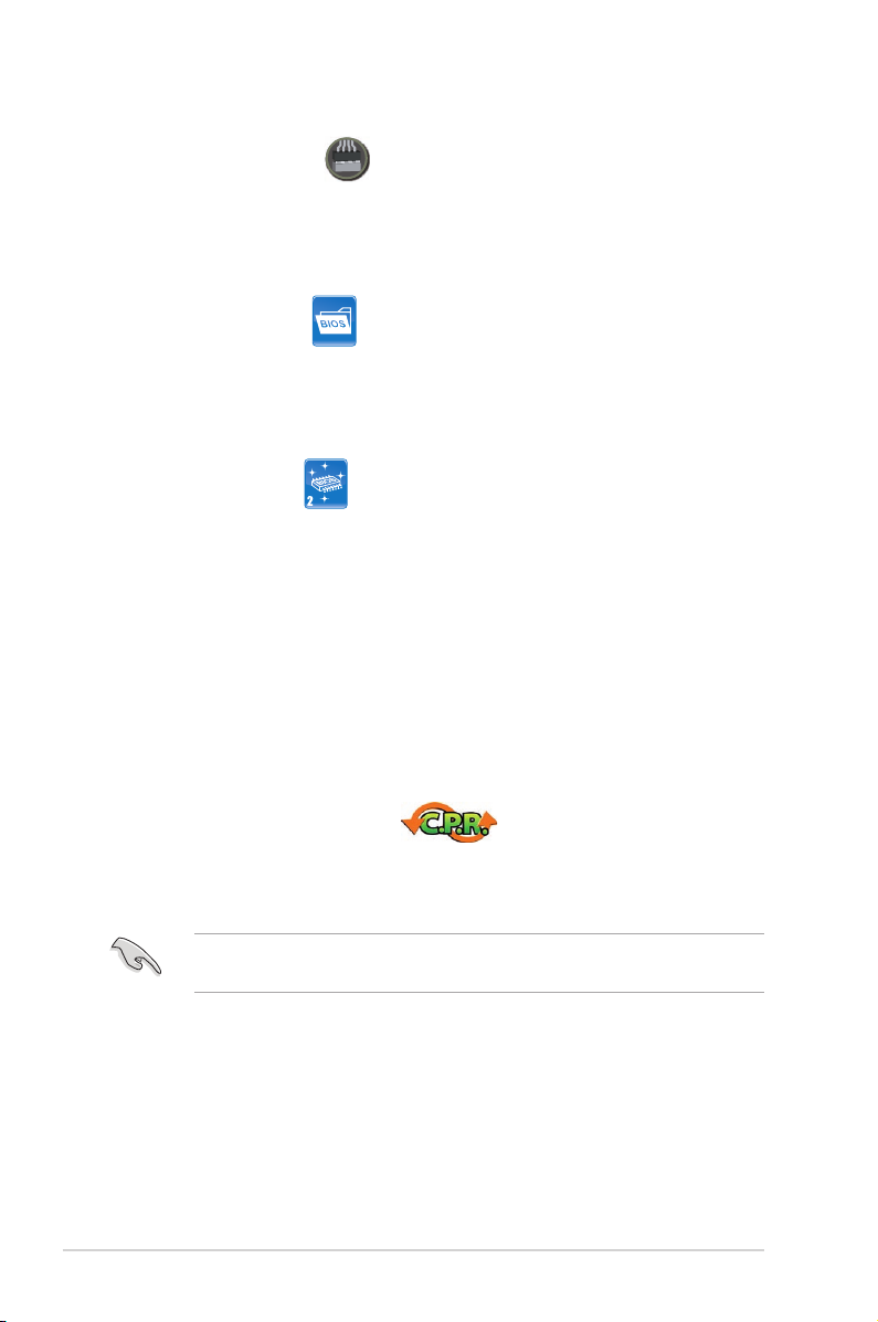
1. CPU LED
The CPU LED has three voltage displays: CPU Voltage, CPU PLL Voltage
and QPI/DRAM Core voltage; you can select the voltage to display in BIOS.
Refer to the illustration below for the location of the CPU LED and the table
below for LED denition.
Normal (green) High (yellow) Crazy (red)
CPU Voltage 0.85000–1.5000 1.50625–1.59375 1.60000–
CPU PLL Voltage 1.81592–1.89542 1.90867–1.94842 1.96167–
QPI/DRAM Core Voltage 1.20000–1.39375 1.40000–1.65625 1.66250–
2-2 Chapter 2: Hardware information
Page 27
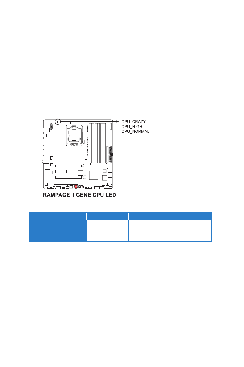
2. Northbridge/Southbridge LEDs
The northbridge and southbridge LEDs each have two different voltage
displays. The northbridge LED displays either the IOH Voltage or the IOH
PCIE Voltage. The southbridge LED shows either the ICH Voltage or the ICH
PCIE Voltage. You can select the voltage to display in BIOS. Refer to the
illustration below for the location of the northbridge/southbridge LEDs and the
table below for LED denition.
Normal (green) High (yellow) Crazy (red)
IOH Voltage 1.11341–1.39166 1.40491–1.64341 1.65666–
IOH PCIE Voltage 1.51106–1.69656 1.70981–1.84231 1.85556–
ICH Voltage 1.11341–1.59041 1.60366–1.84216 1.85541–
ICH PCIE Voltage 1.51106–1.61706 1.63031–1.80256 1.81581–
ROG Rampage II GENE 2-3
Page 28
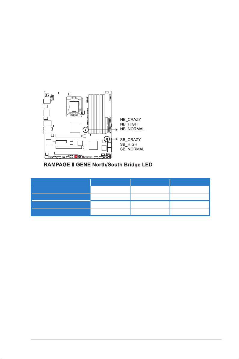
3. Memory LED
Refer to the illustration below for the location of the memory LED and the
table below for LED denition.
Normal (green) High (yellow) Crazy (red)
DRAM Bus Voltage 1.51106–1.72306 1.73631–2.31931 2.33256–
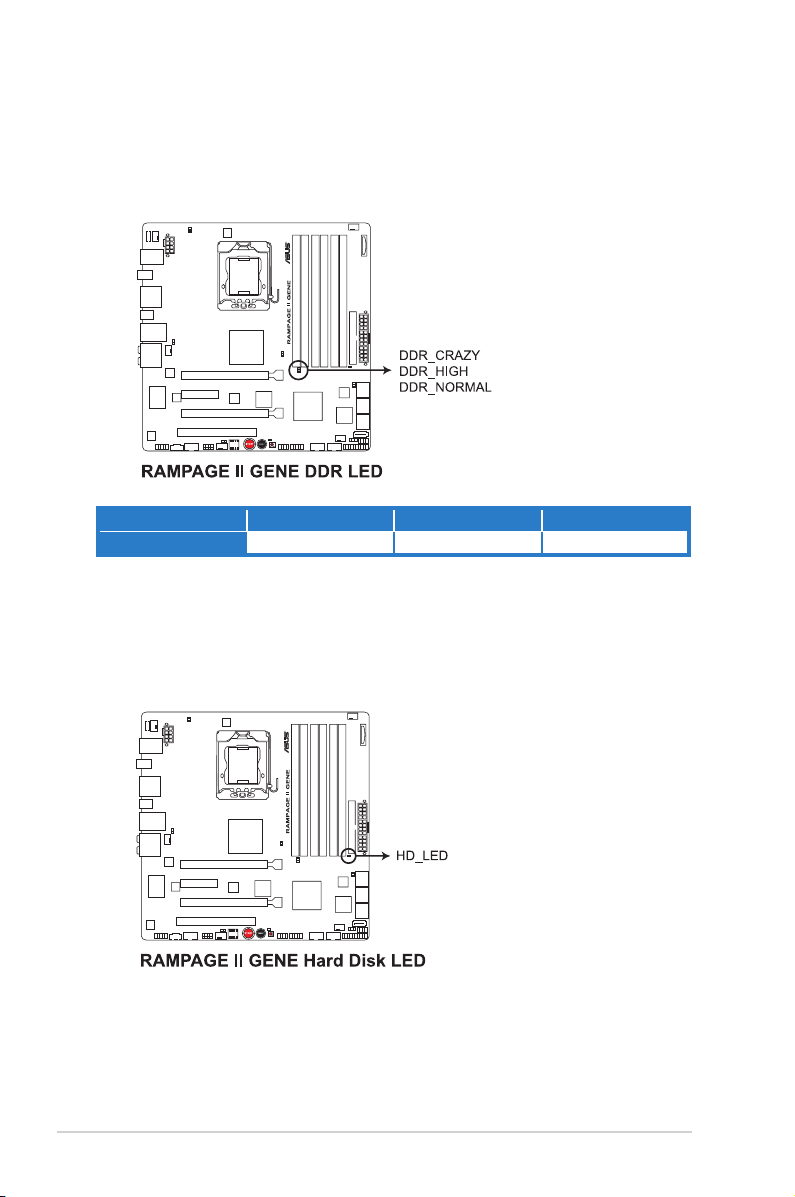
4. Hard Disk LED
The hard disk LED is designed to indicate the hard disk activity. It blinks when
data is being written into or read from the hard disk drive. The LED does not
light up when there is no hard disk drive connected to the motherboard or
when the hard disk drive does not function.
2-4 Chapter 2: Hardware information
Page 29
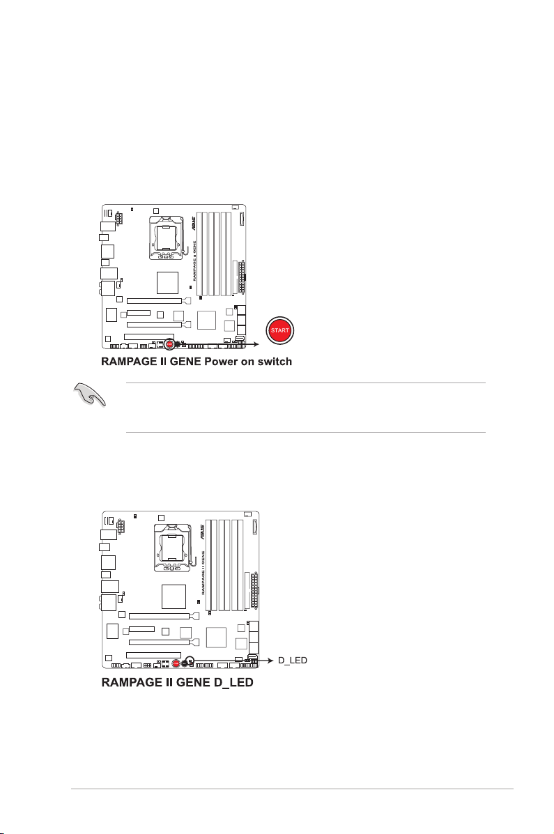
5. Power LED
The motherboard comes with a power-on switch that lights up to indicate
that the system is ON, in sleep mode, or in soft-off mode. This is a reminder
that you should shut down the system and unplug the power cable before
removing or plugging in any motherboard component. The illustration below
shows the location of the onboard power-on switch.
When you turn on the ATX power supply, the Power LED ashes three times
to indicate that the system is ready to boot. Wait till the ash stops before you
press the power-on switch.
6. MemOK! LED
The MemOK! LED blinks while the system is loading failsafe settings for
memory compatibility after pressing the MemOK! switch.
ROG Rampage II GENE 2-5
Page 30
2.2 Motherboard overview
2.2.1 Motherboard layout
2-6 Chapter 2: Hardware information
Page 31

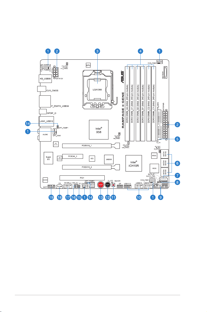
2.2.2 Layout contents
Connectors/Jumpers/Switches/Slots Page
1. CPU, chassis, and optional fan connectors (4-pin CPU_FAN;
3-pin CHA_FAN1–2; 3-pin OPT_FAN1–2)
2. ATX power connectors (24-pin EATXPWR, 8-pin EATX12V) 2-37
3. LGA1366 CPU Socket 2-10
4. DDR3 DIMM slots 2-15
5. IDE connector (40-1 pin PRI_EIDE) 2-30
6. ICH10R Serial ATA connectors (7-pin SATA1–6 [blue]) 2-31
7. JMicron JMB363® Serial ATA connector (7-pin SATA_E1 [black]) 2-32
8. Clear RTC RAM (3-pin CLRTC_SW) 2-27
9. System panel connector (20-8 pin PANEL) 2-38
10. USB connectors (10-1 pin USB78; USB910; USB1112) 2-32
11. MemOK! switch 2-41
12. Reset switch 2-40
13. Power-on switch 2-40
14. Thermal sensor cable connectors (2-pin OPT_TEMP1–2) 2-36
15. Chassis intrusion connector (4-1 pin CHASSIS) 2-36
16. Digital audio connector (4-1 pin SPDIF_OUT) 2-33
17. IEEE 1394a port connector (10-1 pin IE1394_2) 2-33
18. Optical drive audio connector (4-pin CD) 2-34
19. Front panel audio connector (10-1 pin AAFP) 2-34
Refer to 2.7 Connectors for more information about rear panel connectors and
internal connectors.
2-35
ROG Rampage II GENE 2-7
Page 32

2.2.3 Placement direction
When installing the motherboard, ensure that you place it into the chassis in
the correct orientation. The edge with external ports goes to the rear part of the
chassis as indicated in the image below.
2.2.4 Screw holes
Place eight (8) screws into the holes indicated by circles to secure the motherboard
to the chassis.
DO NOT overtighten the screws! Doing so can damage the motherboard.
Place this side towards
the rear of the chassis
2-8 Chapter 2: Hardware information
Page 33

2.3 Central Processing Unit (CPU)
The motherboard comes with a surface mount LGA1366 socket designed for the
Intel® Core™ i7 Processor Extreme Edition / Core™ i7 Processor.
• Ensure that all power cables are unplugged before installing the CPU.
• Connect the chassis fan cable to the CHA_FAN1 connector to ensure
system stability.
• Upon purchase of the motherboard, ensure that the PnP cap is on
the socket and the socket contacts are not bent. Contact your retailer
immediately if the PnP cap is missing, or if you see any damage to the PnP
cap/socket contacts/motherboard components. ASUS will shoulder the cost
of repair only if the damage is shipment/transit-related.
• Keep the cap after installing the motherboard. ASUS will process Return
Merchandise Authorization (RMA) requests only if the motherboard comes
with the cap on the LGA1366 socket.
• The product warranty does not cover damage to the socket contacts
resulting from incorrect CPU installation/removal, or misplacement/loss/
incorrect removal of the PnP cap.
ROG Rampage II GENE 2-9
Page 34

2.3.1 Installing the CPU
To install a CPU:
1. Locate the CPU socket on the motherboard.
Before installing the CPU, ensure that the cam box is facing towards you and
the load lever is on your left.
2. Press the load lever with your
thumb (A), then move it to the left
Retention tab
(B) until it is released from the
retention tab.
To prevent damage to the socket
pins, do not remove the PnP cap
unless you are installing a CPU.
2-10 Chapter 2: Hardware information
A
B
Load lever
Page 35

3. Lift the load lever in the direction of
the arrow to a 135º angle.
4. Lift the load plate with your thumb
and forenger to a 100º angle.
5. Remove the PnP cap from the CPU
socket.
Load plate
4
3
PnP cap
6. Position the CPU over the socket,
ensuring that the gold triangle is on
the bottom-left corner of the socket,
and then t the socket alignment key
into the CPU notch.
The CPU ts in only one correct
orientation. DO NOT force the
CPU into the socket to prevent
bending the connectors on the
socket and damaging the CPU!
ROG Rampage II GENE 2-11
CPU notch
Alignment key
Gold
triangle
mark
Page 36

7. Apply several drops of thermal paste
to the exposed area of the CPU that
the heatsink will be in contact with,
ensuring that it is spread in an even
thin layer.
Some heatsinks come with preapplied thermal paste. If so, skip
this step.
The thermal paste is toxic and
inedible. If it gets into your eyes
or touches your skin, ensure to
wash it off immediately and seek
professional medical help.
To prevent contaminating the paste, DO NOT spread the paste with your nger
directly.
8. Close the load plate (A), and then
push the load lever (B) until it snaps
into the retention tab.
A
B
2-12 Chapter 2: Hardware information
Page 37

2.3.2 Installing the CPU heatsink and fan
The Intel® LGA1366 processor requires a specially designed heatsink and fan
assembly to ensure optimum thermal condition and performance.
• When you buy a boxed Intel® processor, the package includes the CPU fan
and heatsink assembly. If you buy a CPU separately, ensure that you use
only Intel®-certied multi-directional heatsink and fan.
• Your Intel® LGA1366 heatsink and fan assembly comes in a push-pin
design and requires no tool to install.
Ensure that you have installed the motherboard to the chassis before you install
the CPU fan and heatsink assembly.
If you purchased a separate CPU heatsink and fan assembly, ensure that the
Thermal Interface Material is properly applied to the CPU heatsink or CPU
before you install the heatsink and fan assembly.
To install the CPU heatsink and fan:
1. Place the heatsink on top of the
installed CPU, ensuring that the four
fasteners match the holes on the
motherboard.
B
A
B
2. Push down two fasteners at a time
in a diagonal sequence to secure
A
the heatsink and fan assembly in
place.
A
B
ROG Rampage II GENE 2-13
B
1
A
Orient the heatsink and fan assembly such that the CPU fan cable is closest to
the CPU fan connector.
1
Page 38

3. Connect the CPU fan cable to the connector on the motherboard labeled
CPU_FAN.
DO NOT forget to connect the CPU fan connector! Hardware monitoring errors
can occur if you fail to plug this connector.
2.3.3 Uninstalling the CPU heatsink and fan
To uninstall the CPU heatsink and fan:
1. Disconnect the CPU fan cable from
the connector on the motherboard.
2. Rotate each fastener
counterclockwise.
B
A
B
3. Pull up two fasteners at a time in a
diagonal sequence to disengage the
A
heatsink and fan assembly from the
motherboard.
A
B
B
A
4. Carefully remove the heatsink and fan assembly from the motherboard.
2-14 Chapter 2: Hardware information
Page 39

2.4 System memory
2.4.1 Overview
The motherboard comes with six Double Data Rate 3 (DDR3) Dual Inline Memory
Modules (DIMM) sockets.
A DDR3 module has the same physical dimensions as a DDR2 DIMM but is
notched differently to prevent installation on a DDR2 DIMM socket. DDR3 modules
are developed for better performance with less power consumption.
The gure illustrates the location of the DDR3 DIMM sockets:
Channel Sockets
Channel A DIMM_A1 and DIMM_A2
Channel B DIMM_B1 and DIMM_B2
Channel C DIMM_C1 and DIMM_C2
Recommended memory conguration for better performance
Mode
2 DIMMs - Populated - Populated - -
3 DIMMs - Populated - Populated - Populated
4 DIMMs Populated Populated - Populated - Populated
6 DIMMs Populated Populated Populated Populated Populated Populated
ROG Rampage II GENE 2-15
Sockets
DIMM_A2 DIMM_A1 DIMM_B2 DIMM_B1 DIMM_C2 DIMM_C1
Due to Intel CPU spec denition, the system will not boot if only one DIMM is
installed in DIMM slot A2, B2, or C2. Follow the table above for recommended
memory conguration.
Page 40

2.4.2 Memory congurations
You may install 1GB, 2GB and 4GB unbuffered non-ECC DDR3 DIMMs into the
DIMM sockets.
• You may install varying memory sizes in Channel A, Ch annel B and
Channel C. The system maps the total size of the lower-sized channel for
the dual-channel or triple-channel conguration. Any excess memory from
the higher-sized channel is then mapped for single-channel operation.
• Due to Intel spec denition, X.M.P. DIMMs and DDR3-1600 are supported
for one DIMM per channel only.
• According to Intel CPU spec, DIMMs with voltage requirement over 1.65V
may damage the CPU permanently. We recommend you install the DIMMs
with the voltage requirement below 1.65V.
• Always install DIMMs with the same CAS latency. For optimum compatibility,
we recommend that you obtain memory modules from the same vendor.
• Due to the memory address limitation on 32-bit Windows OS, when you
install 4GB or more memory on the motherboard, the actual usable memory
for the OS can be about 3GB or less. For effective use of memory, we
recommend that you install a 64-bit Windows OS when having 4GB or more
memory installed on the motherboard.
• This motherboard does not support DIMMs made up of 256 megabit (Mb)
chips or less.
• The default memory operation frequency is dependent on its SPD. Under the
default state, some memory modules for overclocking may operate at a lower
frequency than the vendor-marked value. To operate at the vendor-marked or
at a higher frequency, see section 3.3 Extreme Tweaker menu for manual
memory frequency adjustment.
• For system stability, use a more efcient memory cooling system to support
a full memory load (6 DIMMs) or overclocking condition.
2-16 Chapter 2: Hardware information
Page 41

Rampage II GENE Motherboard
Qualied Vendors Lists (QVL) DDR3-2000MHz capability
3GB
(Kit of 3)
2GB
(Kit of 2)
SS/DSChip
Brand
SS N/A
SS N/A
Vendor Part No. Size
Crucial BL12864BE2009.8SFB1(EPP) 1GB SS N/A
Crucial BL12864BE2009.8SFB3(EPP) 1GB SS N/A
Crucial BL12864BE2009-8SFB3(EPP) 1GB SS N/A
Crucial BL12864BE2009.8SFB3(EPP) 2GB SS N/A
G.SKILL F3-16000CL9T-3GBDI-B(XMP)
OCZ OCZ3FXT20002GK
Timing
Chip NO.
Dimm(Bios)
Heat-Sink
9-9-9-28 1.9 •
Package
Heat-Sink
9-9-9-28
Package
(1333-9-9-9-24)
Heat-Sink
9-9-9-28
Package
(1333-9-9-9-24)
Heat-Sink
9-9-9-28
Package
(1333-9-9-9-24)
Heat-Sink
9-9-9-24
Package
(2000-9-9-9-24)
Heat-Sink
8 1.9 • •
Package
Voltage
2.0 •
2 • •
2 •
1.65 •
Rampage II GENE Motherboard
Qualied Vendors Lists (QVL) DDR3-1800MHz capability
4GB
(Kit of 2)
2GB
(Kit of 2)
3GB
(Kit of 3)
2GB
(Kit of 2)
SS/DSChip
Brand
DS N/A
SS N/A
SS N/A
SS N/A
Vendor Part No. Size
CORSAIR CM3X1024-1800C7DIN(XMP) 1GB SS N/A
CORSAIR
KINGSTON KHX14400D3/1G 1GB SS N/A
KINGSTON KHX14400D3K2/2GN(EPP)
KINGSTON KHX14400D3K3/3GX(XMP)
Transcend TX1800KLU-2GK(XMP)
BoxP/N:TW3X4G1800C8DF
(CM3X2G1800C8D)Ver4.1
Timing
Chip NO.
DIMM (BIOS)
Heat-Sink
7 •
Package
Heat-Sink
8-8-8-24 1.80 •
Package
Heat-Sink
Package
Heat-Sink
Package
Heat-Sink
(1333-9-9-9-24) 1.65 • •
Package
Heat-Sink
8 • •
Package
Voltage
1.9 •
1.9 • •
DIMM socket
support (Optional)
A* B*
DIMM socket
support (Optional)
A* B*
Side(s): SS - Single-sided DS - Double-sided
DIMM support:
• A*: Supports two (2) modules inserted into slot A1 and B1 as one pair of
Dual-channel memory conguration.
• B*: Supports three (3) modules inserted into the orange slots (A1, B1 and
C1) as one set of Triple-channel memory conguration.
• ASUS exclusively provides hyper DIMM support function.
• Hyper DIMM support is subject to the physical characteristics of individual
CPUs.
• Visit the ASUS website for the latest QVL.
ROG Rampage II GENE 2-17
Page 42

Rampage II GENE Motherboard
Qualied Vendors Lists (QVL) DDR3-1600MHz capability
3GB
(Kit of 3)
6GB
(Kit of 3)
2GB
(Kit of 2)
3GB
(Kit of 3)
3GB
(Kit of 3)
4GB
(Kit of 2)
4GB
(Kit of 2)
6GB
(Kit of 3)
6GB
(Kit of 3)
2GB
(Kit of 2)
2GB
(Kit of 2)
4GB
(Kit of 2)
6GB
(Kit of 3)
6GB
(Kit of 3)
3GB
(Kit of 3)
4GB
(Kit of 2)
6GB
(Kit of 3)
2GB
(Kit of 2)
3GB
(Kit of 3)
4GB
(Kit of 2)
4GB
(Kit of 2)
6GB
(Kit of 3)
SS/
DS
SS N/A
DS N/A
SS N/A
SS N/A
SS N/A
DS N/A
DS N/A
DS N/A
DS N/A
SS N/A
SS N/A
DS N/A
DS N/A
DS N/A
SS N/A
SS N/A
DS N/A
SS N/A
SS N/A
DS N/A
DS N/A
DS N/A
Chip Chip NO.
Vendor Part No. Size
A-DATA AD31600E001GMU(XMP)
A-DATA AD31600F002GMU(XMP)
CORSAIR
CORSAIR TR3X3G1600C8D(XMP)Ver2.1
CORSAIR TR3X3G1600C9(XMP)Ver1.1
CORSAIR
CORSAIR
CORSAIR TR3X6G1600C8D(XMP)Ver2.1
CORSAIR TR3X6G1600C9(XMP)Ver2.1
Crucial BL12864BA1608.8SFB(XMP) 1GB SS N/A
G.SKILL F3-12800CL7D-2GBHZ
G.SKILL F3-12800CL9D-2GBNQ
G.SKILL F3-12800CL7D-4GBPI
G.Skill F3-12800CL8T-6GBHK(XMP)
G.SKILL F3-12800CL9T-6GBNQ
KINGSTON KHX12800D3LLK3/3GX(XMP)
KINGSTON KHX12800D3K2/4G
KINGSTON KHX12800D3LLK/6GX(XMP)
OCZ OCZ3P1600EB1G 1GB SS N/A
OCZ OCZ3T1600XM2GK(XMP)
OCZ OCZ3G1600LV3GK
OCZ OCZ3P16004GK
OCZ OCZ3P1600EB4GK
OCZ OCZ3G1600LV6GK
Aeneon AXH760UD10-16H 1GB SS N/A
Aeneon AXH860UD20-16H 2GB DS N/A
BoxP/N:TWIN3X2048-1600C7DHXIN
(CM3X1024-1600C7DHXIN)(XMP)Ver3.1
BoxP/N:TW3X4G1600C9DHXNV
(CM3X2G1600C9DHXNV)Ver4.1
BoxP/N:TWIN3X4096-1600C7DHXIN
(CM3X2048-1600C7DHXIN)Ver3.1
Heat-Sink
Package
Heat-Sink
Package
Heat-Sink
Package
Heat-Sink
Package
Heat-Sink
Package
Heat-Sink
Package
Heat-Sink
Package
Heat-Sink
Package
Heat-Sink
Package
Heat-Sink
Package
Heat-Sink
Package
Heat-Sink
Package
Heat-Sink
Package
Heat-Sink
Package
Heat-Sink
Package
Heat-Sink
Package
Heat-Sink
Package
Heat-Sink
Package
Heat-Sink
Package
Heat-Sink
Package
Heat-Sink
Package
Heat-Sink
Package
Heat-Sink
Package
Heat-Sink
Package
Heat-Sink
Package
Heat-Sink
Package
Timing
Dimm(Bios)
8-8-8-24
(1333-9-9-9-24)
7-7-7-20
(1333-9-9-9-24)
7-7-7-20
(1333-9-9-9-24)
8-8-8-24
(1601-8-8-8-24)
9-9-9-24
(1601-9-9-9-24)
(1333-9-9--9-24) 1.80 • • •
(1601-7-7-7-20) 1.90 • •
8-8-8-24
(1601-8-8-8-24)
9-9-9-24
(1333-9-9-9-24)
(1601-8-8-8-24) 1.8 • • • •
(1601-7-7-7-18) 1.9 • • • •
(1333-9-9-9-24) 1.6 • • •
7-7-7-18
(1333-9-9-9-24)
8-8-8-21
(1333-8-8-8-21)
9-9-9-24
(1601-9-9-9-24)
(1333-9-9-9-24) 1.65 • • •
(1066-7-7-7-20) 1.9 • • •
1600-8-8-8-20 1.65 • • • •
7-6-6-24
(1333-7-7-7-20)
(1601-8-8-8-28) • • • •
8-8-8
(1066-7-7-7-20)
7-7-7
(1333-7-7-7-20)
7-7-6
(1333-7-7-7-20)
8-8-8
(1066-7-7-7-20)
(1601-9-9-9-28) • • • •
(1601-9-9-9-28) • • • •
DIMM socket support
(Optional)
Voltage
A* B* C* D*
1.65-
• • • •
1.85
1.75-
• • • •
1.85
1.80 • • • •
1.65 • •
1.65 • •
1.65 • • •
1.65 • • •
1.9 •
1.6-
• • • •
1.65
1.5-1.6 • • • •
•
1.65 • • • •
1.9 •
1.8 • • • •
1.65 • •
2-18 Chapter 2: Hardware information
Page 43

Rampage II GENE Motherboard
Qualied Vendors Lists (QVL) DDR3-1600MHz capability (continued)
DIMM socket support
(Optional)
Voltage
A* B* C* D*
1.7-1.9 • • •
• • • •
1.65 • • •
2.0 • • • •
1.65 • • • •
1.65 • • • •
2GB
(Kit of 2)
4GB
(Kit of 2)
3GB
(Kit of 3)
4GB
(Kit of 2)
6GB
(Kit of 3)
6GB
(Kit of 3)
SS/
Chip Chip NO.
DS
DS N/A
DS N/A
SS N/A
DS N/A
DS N/A
DS N/A
Vendor Part No. Size
Cell Shock CS322271
Elixier M2F2G64CB8HA4N-DG 2GB DS Elixir
Mushkin 996657
Patriot PVT33G1600ELK
Patriot PVS34G1600LLKN
Patriot PVT36G1600ELK
Patriot PVT36G1600ELK
Heat-Sink
Package
N2CB1G80AN-DG9
Heat-Sink
Package
Heat-Sink
Package
Heat-Sink
Package
Heat-Sink
Package
Heat-Sink
Package
Timing
Dimm(Bios)
7-7-7-14
(1066-7-7-7-20)
(1333-9-9-9-28)
7-7-7-20 • • • •
9-9-9-24
(1066-7-7-7-20)
7-7-7-20
(1066-7-7-7-20)
9-9-9-24
(1066-7-7-7-20)
9-9-9-24
(1600-7-7-7-20)
Rampage II GENE Motherboard
Qualied Vendors Lists (QVL) DDR3-1333MHz capability
DIMM socket
Vendor Part No. Size
A-DATA AD31333E002G0U
Apacer 78.01GC6.420 1GB SS ELPIDA J1108BABG-DJ-E (1333-9-9-9-24) • • • •
Apacer 78.01GC8.422 1GB SS ELPIDA J1108BABG-DJ-E(ECC) (1333-9-9-9-24) • • • •
Apacer 78.A1GC6.421 2GB DS ELPIDA J1108BABG-DJ-E (1333-9-9-9-24) • • • •
Apacer 78.A1GC8.423 2GB DS ELPIDA J1108BABG-DJ-E(ECC) (1333-9-9-9-24) • • • •
CORSAIR TR3X3G1333C9 (Ver2.1)
CORSAIR CM3X1024-1333C9DHX 1GB DS N/A Heat-Sink Package (1333-9-9-9-24) 1.1 • •
CORSAIR
CORSAIR TR3X6G1333C9 (Ver2.1)
Crucial CT12864BA1339.8SFB 1GB SS MICRON D9GTS (1333-9-9-9-24) • • • •
Crucial CT12864BA1339.8SFD 1GB SS MICRON MT8JF12864AY-1G4D1 (1333-9-9-9-24) • • • •
Crucial CT25664BA1339.16SFD 2GB DS MICRON D9JNM (1333-9-9-9-24) • • • •
ELPIDA EBJ10UE8BAW0-DJ-E 1GB SS ELPIDA J1108BABG-DJ-E 9 (1333-9-9-9-24) • • • •
ELPIDA EBJ11UD8BAFA-DJ-E 1GB DS ELPIDA J5308BASE-DJ-E (1333-9-9-9-24) •
ELPIDA EBJ21UE8BAW0-DJ-E 2GB DS ELPIDA J1108BABG-DJ-E 9 (1333-9-9-9-24) • • • •
G.SKILL F3-10600CL7D-2GBPI
G.SKILL F3-10600CL8D-2GBHK
BoxP/N:TWIN3X2048-1333C9
(CM3X1024-1333C9)Ver1.1
SS/DSChip
Brand
6GB
DS N/A Heat-Sink Package
(Kit of 3)
3GB
SS N/A Heat-Sink Package
(Kit of 3)
2GB
DS N/A Heat-Sink Package
(Kit of 2)
6GB
DS N/A Heat-Sink Package
(Kit of 3)
2GB
SS N/A Heat-Sink Package (1337-7-7-7-18) 1.65 • • •
(Kit of 2)
2GB
SS N/A Heat-Sink Package (1337-8-8-8-22) 1.65 • • • •
(Kit of 2)
Chip NO.
Timing
DIMM (BIOS)
7-7-7-20
(1333-9-9-9-24)
9-9-9-24
(1333-9-9-9-24)
9-9-9-24
(1066-7-7-7-20)
9-9-9-24
(1333-9-9-9-24)
support (Optional)
Voltage
A* B* C* D*
1.65-
• • • •
1.85
1.5 • • • •
1.70 • • • •
1.5 • • •
ROG Rampage II GENE 2-19
Page 44

Rampage II GENE Motherboard
Qualied Vendors Lists (QVL) DDR3-1333MHz capability (continued)
DIMM socket
Vendor Part No. Size
G.SKILL F3-10600CL9D-2GBNQ
G.Skill F3-10666CL7T-6GBPK(XMP) 2GB DS N/A Heat-Sink Package
G.Skill F3-10666CL8D-4GBHK(XMP)
G.SKILL F3-10666CL9T-6GBNQ
Hynix HMT112U6BFR8C-H9 1GB SS Hynix H5TQ1G83BFR 9 (1333-9-9-9-24) • •
KINGMAX FLFD45F-B8EE9 1GB SS ELPIDA J1108BASE-DJ-E (1333-9-9-9-24) • • • •
KINGSTON KVR1333D3N9/1G 1GB SS ELPIDA J1108BASE-DJ-E (1333-9-9-9-24) 1.5 • • • •
KINGSTON KVR1333D3N9/2G 2GB DS ELPIDA J1108BASE-DJ-E (1333-9-9-9-24) 1.5 • • • •
MICRON MT8JTF12864AY-1G4BYES 1GB SS MICRON Z9HWR (1333-9-9-9-24) • •
MICRON MT16JTF25664AY-1G4BYES 2GB DS MICRON Z9HWR (1333-9-9-9-24) • • • •
OCZ OCZ3RPX1333EB2GK 1GB SS N/A Heat-Sink Package (1066-6-5-5-20) • • •
OCZ OCZ3P13332GK 1GB DS N/A Heat-Sink Package
OCZ OCZ3G13334GK
OCZ OCZ3G1333LV6GK
OCZ OCZ3P1333LV6GK
Qimonda IMSH2GU13A1F1C-13H 2GB DS Qimonda IDSH1G-03A1F1C-13H 9 (1333-9-9-9-24) • • • •
SAMSUNG M378B2873DZ1-CH9 1GB SS SAMSUNG K4B1G0846D 9 (1333-9-9-9-24) • • • •
SAMSUNG M391B2873DZ1-CH9 1GB SS SAMSUNG K4B1G0846D(ECC) 9 (1333-9-9-9-24) • •
SAMSUNG M378B5673DZ1-CH9 2GB DS SAMSUNG K4B1G0846D 9 (1333-9-9-9-24) • • • •
SAMSUNG M391B5673DZ1-CH9 2GB DS SAMSUNG K4B1G0846D(ECC) 9 (1333-9-9-9-24) • • • •
Transcend TS128MLK64V3U 1GB SS SAMSUNG K4B1G0846D 9 (1333-9-9-9-24) • • • •
Transcend TS256MLK64V3U 2GB DS SAMSUNG K4B1G0846D 9 (1333-9-9-9-24) • • •
Aeneon AEH760UD00-13H 1GB DS AENEON AEH93R13H (1333-9-9-9-24) •
Asint SLY3128M8-EDJ 1GB SS Asint DDRIII1208-DJ (9-9-9-24) • • • •
Asint SLZ3128M8-EDJ 2GB DS Asint DDRIII1208-DJ (9-9-9-24) • • • •
ASUS N/A 1GB DS N/A Heat-Sink Package (1333-9-9-9-24) • • •
Elixir M2F2G64CB8HA4N-CG 2GB DS Elixir N2CB1G80AN-CG (1333-9-9-9-24) • • •
Patriot PDC32G1333LLK 1GB SS PATRIOT Heat-Sink Package 7 (1337-7-7-7-20) 1.7 • • •
Patriot PVT33G1333ELK
Patriot PVT36G1333ELK
SS/DSChip
Brand
2GB
DS N/A Heat-Sink Package (1333-9-9-9-24)
(Kit of 2)
4GB
DS N/A Heat-Sink Package
(Kit of 2)
6GB
DS N/A Heat-Sink Package
(Kit of 3)
4GB
DS N/A Heat-Sink Package 9 (1066-8-9-9-20) 1.7 •
(Kit of 2)
6GB
DS N/A Heat-Sink Package
(Kit of 3)
6GB
DS N/A Heat-Sink Package
(Kit of 3)
3GB
SS N/A Heat-Sink Package
(Kit of 3)
6GB
DS N/A Heat-Sink Package
(Kit of 3)
Chip NO.
Timing
DIMM (BIOS)
7-7-7-18
(1333-7-7-7-18)
8-8-8-21
(1333-7-7-7-20)
9-9-9-24
(1333-9-9-9-24)
7-7-7-20
(1333-9-9-9-24)
9-9-9
(1066-7-7-7-20)
7-7-7
(1066-7-7-7-20)
9-9-9-24
(1066-7-7-7-20)
9-9-9-24
(1066-7-7-7-20)
support (Optional)
Voltage
A* B* C* D*
1.5-
• • • •
1.65
1.5-1.6 • • • •
1.5-1.6 • • • •
1.5 • • • •
•
1.65 • •
1.65 • • •
1.65 • • •
1.65 • • • •
2-20 Chapter 2: Hardware information
Page 45

Rampage II GENE Motherboard
Qualied Vendors Lists (QVL) DDR3-1067MHz capability
DIMM socket
Vendor Part No. Size
CORSAIR CM3X1024-1066C7 1GB DS N/A Heat-Sink Package 7 1.1 • • •
Crucial CT12864BA1067.8SFB 1GB SS MICRON Z9HWQ 7 • • •
Crucial CT12864BA1067.8SFD 1GB SS MICRON D9JNL 7 • • • •
Crucial CT25664BA1067.16SFD 2GB DS MICRON D9JNL 7 • • • •
ELPIDA EBJ10UE8BAW0-AE-E 1GB SS ELPIDA J1108BABG-DJ-E 7(1066-7-7-7-20) • • •
ELPIDA EBJ11RD8BAFA-AE-E 1GB DS ELPIDA J5308BASE-AC-E(ECC) 7 • • •
ELPIDA EBJ21UE8BAW0-AE-E 2GB DS ELPIDA J1108BABG-DJ-E 7(1066-7-7-7-20) • • •
Hynix HMT112U6AFP8C-G7N0 1GB SS HYNIX H5TQ1G83AFPG7C 7 • • • •
Hynix HYMT112U64ZNF8-G7 1GB SS HYNIX HY5TQ1G831ZNFP-G7 7 • •
Hynix
Hynix HYMT125U64ZNF8-G7 2GB DS HYNIX HY5TQ1G831ZNFP-G7 7 • • •
KINGSTON KVR1066D3N7/1G 1GB DS ELPIDA J5308BASE-AC-E 1.5 • • • •
KINGSTON KVR1066D3N7/2G 2GB DS SAMSUNG K4B1G0846C-ZCF8 1.5 • • •
MICRON MT8JTF12864AY-1G1D1 1GB SS MICRON 7VD22 7 • •
HMT125U6AFP8CG7N0
SS/DSChip
Brand
2GB DS HYNIX H5TQ1G83AFPG7C 7 • • • •
Chip NO.
Timing
DIMM (BIOS)
Side(s): SS - Single-sided DS - Double-sided
DIMM support:
• A*: Supports two (2) modules inserted into slot A1 and B1 as one pair of
Dual-channel memory conguration.
• B*: Supports three (3) modules inserted into the orange slots (A1, B1 and
C1) as one set of Triple-channel memory conguration.
• C*: Supports four (4) modules inserted into the orange slots (A1, B1 and
C1) and the black slot A2 as one set of Triple-channel memory
conguration.
• D*: Supports six (6) modules inserted into both the orange slots and the
black slots as two set of Triple-channel memory conguration.
Voltage
support (Optional)
A* B* C* D*
• According to Intel spec denition, DDR3-1600 is supported for one DIMM
per channel only. ASUS exclusively provides two DDR3-1600 DIMM
support for each memory channel.
• Visit the ASUS website for the latest QVL.
ROG Rampage II GENE 2-21
Page 46

2.4.3 Installing a DIMM
Ensure to unplug the power supply before adding or removing DIMMs or other
system components. Failure to do so may cause severe damage to both the
motherboard and the components.
1. Unlock a DIMM socket by
pressing the retaining clip
outward.
2. Align a DIMM on the socket
such that the notch on the DIMM
matches the break on the socket.
A DIMM is keyed with a notch so that it ts in only one direction. DO NOT force
a DIMM into a socket to avoid damaging the DIMM.
3. Firmly insert the DIMM into the
socket until the retaining clip
snaps back in place and the
DIMM is properly seated.
2.4.4 Removing a DIMM
Follow these steps to remove a DIMM.
1. Press the retaining clip outward
to unlock the DIMM.
2
DIMM notch
1
Unlocked retaining clip
3
Locked Retaining Clip
2
1
Support the DIMM lightly with your ngers when pressing the retaining clips.
The DIMM might get damaged when it ips out with extra force.
2. Remove the DIMM from the socket.
2-22 Chapter 2: Hardware information
Page 47

2.5 Expansion slots
In the future, you may need to install expansion cards. The following sub-sections
describe the slots and the expansion cards that they support.
Ensure to unplug the power cord before adding or removing expansion cards.
Failure to do so may cause you physical injury and damage motherboard
components.
2.5.1 Installing an expansion card
To install an expansion card:
1. Before installing the expansion card, read the documentation that came with
it and make the necessary hardware settings for the card.
2. Remove the system unit cover (if your motherboard is already installed in a
chassis).
3. Remove the bracket opposite the slot that you intend to use. Keep the screw
for later use.
4. Align the card connector with the slot and press rmly until the card is
completely seated on the slot.
5. Secure the card to the chassis with the screw you removed earlier.
6. Replace the system cover.
2.5.2 Conguring an expansion card
After installing the expansion card, congure it by adjusting the software settings.
1. Turn on the system and change the necessary BIOS settings, if any. See
Chapter 3 for information on BIOS setup.
2. Assign an IRQ to the card. Refer to the tables on the next page.
3. Install the software drivers for the expansion card.
When using PCI cards on shared slots, ensure that the drivers support “Share
IRQ” or that the cards do not need IRQ assignments. Otherwise, conicts will
arise between the two PCI groups, making the system unstable and the card
inoperable. Refer to the table on the next page for details.
ROG Rampage II GENE 2-23
Page 48

2.5.3 Interrupt assignments
Standard interrupt assignments
IRQ Priority Standard function
0 1 System Timer
1 2 Keyboard Controller
2 – Redirect to IRQ#9
4 12 Communications Port (COM1)*
5 13 IRQ Holder for PCI Steering*
6 14 Reserved
7 15 Reserved
8 3 System CMOS/Real Time Clock
9 4 IRQ Holder for PCI Steering*
10 5 IRQ Holder for PCI Steering*
11 6 IRQ Holder for PCI Steering*
12 7 Reserved
13 8 Numeric Data Processor
14 9 Primary IDE Channel
* These IRQs are usually available for PCI devices.
IRQ assignments for this motherboard
IOH
24 25 26 27 28 29 30 31
PCIE16_1 shared – – – – – – –
PCIE16_2 – – – – – – shared –
ICH
A B C D E F G H
PCIE4_1 shared – – – – – –
LAN – – shared – – – – –
PCI_1 shared – – – – – – –
USB controller 1 – – – – – – – shared
USB controller 2 – – – shared – – – –
USB controller 3 – – shared – – – – –
USB controller 4 shared – – – – – – –
USB controller 5 – – – – – shared – –
USB controller 6 – – – shared – – – –
USB 2.0 controller 1 – – – – – – – shared
USB 2.0 controller 2 – – shared – – – – –
SATA controller 1 – – – – shared – – –
SATA controller 2 – – – – shared – – –
Audio Azalia – – – – – – shared –
2-24 Chapter 2: Hardware information
Page 49

2.5.4 PCI slot
The PCI slot supports cards such as a LAN card, SCSI card, USB card, and other
cards that comply with PCI specications. Refer to the gure below for the location
of the slot.
2.5.5 PCI Express x4 slot
This motherboard supports PCI Express x4 network cards, SCSI cards and other
cards that comply with the PCI Express specications. Refer to the gure below for
the location of the slots.
Install a PCIe x4 or PCIe x1 device to a PCIe x4 slot prior to a PCIe x16 slot.
2.5.6 PCI Express 2.0 x16 slots
This motherboard has two PCI Express 2.0 x16 slots that support PCI Express
x16 2.0 graphic cards complying with the PCI Express specications. Refer to the
gure below for the location of the slots.
PCI Express x4 slot
PCI Express 2.0 x16_2 slot
PCI Express 2.0 x16_1 slot
ROG Rampage II GENE 2-25
PCI slot
Page 50

• In single VGA card mode, use rst the PCIe 2.0 x16_1 slot for a PCI
Express x16 graphics card to get better performance.
• In CrossFireX™ or SLI™ mode, use the PCIe 2.0 x16_1 and
PCIe 2.0 x16_2 (blue) slots for PCI Express x16 graphics cards to get
better performance.
• We recommend that you provide sufcient power when running
CrossFireX™ or SLI™ mode. See page 2-37 for details.SLI™ mode. See page 2-37 for details.mode. See page 2-37 for details.
• Connect a chassis fan to the motherboard connector labeled CHA_FAN1/2
when using multiple graphics cards for better thermal environment. See
page 2-35 for details.
2-26 Chapter 2: Hardware information
Page 51

2.6 Jumper
Clear RTC RAM (3-pin CLRTC_SW)
This jumper allows you to enable the clr CMOS switch on the back I/O. You can
clear the CMOS memory and system setup parameters by erasing the CMOS RTC
RAM data. The clr CMOS switch on the back I/O helps you easily clear the system
setup information such as system passwords.
To erase the RTC RAM:
1. Press down the clr CMOS switch on the back I/O.
2. Hold down the <Del> key during the boot process and enter BIOS setup to
re-enter data.
clr CMOS switch behavior
System power state G3* S5* S0 (DOS mode) S0 (OS mode) S1 S3 S4
Clearing CMOS **
*G3: Power off without +5VSB power (AC power loss); S5: Power off with +5VSB power
**The system shuts dowm immediately.
• The clr CMOS switch will not function if the CLRTC_SW jumper is moved
to the Disable position, but the shutdwon function in S0 mode (DOS mode)
still works.
• Ensure to re-enter your previous BIOS settings after you clear the CMOS.
• You do not need to clear the RTC when the system hangs due to CPU
overclocking. With the C.P.R. (CPU Parameter Recall) feature, shut down
and reboot the system so the BIOS can automatically reset CPU parameter
settings to default values. If the system hangs due to overclocking of
memory timing or chipset voltage and the power button fails to function,
pressing down the clr CMOS switch will shut down the system and clear
CMOS simultaneously.
ROG Rampage II GENE 2-27
Page 52

2.7 Connectors
SPEED
LED
ACTIVITY/
LINK LED
LAN port
2.7.1 Rear panel connectors
1. PS/2 keyboard port (purple). This port is for a PS/2 keyboard.
2. USB 2.0 ports 3 and 4. These 4-pin Universal Serial Bus (USB) ports are
available for connecting USB 2.0 devices.
3. LAN (RJ-45) port. This port allows Gigabit connection to a Local Area
Network (LAN) through a network hub. Refer to the table below for the LAN
port LED indications.
LAN port LED indications
Activity/Link Speed LED Description
OFF OFF Soft-off Mode
YELLOW* OFF During Power ON/OFF
YELLOW* ORANGE 100 Mbps connection
YELLOW* GREEN 1 Gbps connection
* Blinking
4. USB 2.0 ports 5 and 6. These 4-pin Universal Serial Bus (USB) ports are
available for connecting USB 2.0 devices.
5. Clear CMOS switch. Press the clear CMOS switch to clear setup information
when the system hangs due to overclocking.
2-28 Chapter 2: Hardware information
Page 53

6. IEEE 1394a port. This 6-pin IEEE 1394a port provides high-speed
connectivity for audio/video devices, storage peripherals, PCs, or portable
devices.
7. External SATA port. This port connects to an external Serial ATA hard disk
drive.
• DO NOT insert a SATA connector into this external SATA port.
• To enable hot-plugging, set the Controller Mode item in the BIOS setting
to [AHCI], and then reboot the system. See section 3.5.3 Onboard Device
Conguration for details.
8. Optical S/PDIF Out port. This port connects an external audio output device
via an optical S/PDIF cable.
9. USB 2.0 ports 1 and 2. These 4-pin Universal Serial Bus (USB) ports are
available for connecting USB 2.0 devices.
10. Audio I/O ports. These ports connect to a 2, 4, 6, or 8-channel audio
system.
Refer to the audio conguration table on the next page for the function of the
audio ports in 2, 4, 6, or 8-channel conguration.
Audio 2, 4, 6, or 8-channel conguration
Port
Light Blue Line In Line In Line In Line In
Lime Line Out Front Speaker Out Front Speaker Out Front Speaker Out
Pink Mic In Mic In Mic In Mic In
Orange – – Center/Subwoofer Center/Subwoofer
Black – Rear Speaker Out Rear Speaker Ou Rear Speaker Out
Gray – – – Side Speaker Out
Headset
2-channel
4-channel 6-channel 8-channel
ROG Rampage II GENE 2-29
Page 54

2.7.2 Internal connectors
1. IDE connector (40-1 pin PRI_EIDE)
The onboard IDE connector is for the Ultra DMA 133/100/66 signal cable.
There are three connectors on each Ultra DMA 133/100/66 signal cable:
blue, black, and gray. Connect the blue connector to the motherboard’s IDE
connector, then select one of the following modes to congure your device.
Drive jumper setting Mode of
device(s)
Single device Cable-Select or Master - Black
Two devices Cable-Select Master Black
Slave Gray
Master Master Black or gray
Slave Slave
• Pin 20 on the IDE connector is removed to match the covered hole on the
Ultra DMA cable connector. This prevents incorrect insertion when you
connect the IDE cable.
• Use the 80-conductor IDE cable for Ultra DMA 133/100/66 IDE devices.
If any device jumper is set as “Cable-Select,” ensure all other device jumpers
have the same setting.
Cable connector
2-30 Chapter 2: Hardware information
Page 55

2. ICH10R Serial ATA connectors (7-pin SATA 1-6 [blue])
These connectors are for the Serial ATA signal cables for Serial ATA hard disk
drives and optical disc drives.
If you installed Serial ATA hard disk drives, you can create a RAID 0, 1, 5,
and 10 conguration with the Intel® Matrix Storage Technology through the
onboard Intel® ICH10R RAID controllers.
•
These connectors are set to Standard IDE mode by default. In Standard
IDE mode, you can connect Serial ATA boot/data hard disk drives to these
connectors. If you intend to create a Serial ATA RAID set using these
connectors, set the Congure SATA as item in the BIOS to [RAID]. See
section 3.4.5 Storage Conguration for details.
•
You must install Windows® XP Service Pack 1 or later version before using
Serial ATA hard disk drives. The Serial ATA RAID feature is available only if
you are using Windows® XP SP1 or later version.
•
When using hot-plug and NCQ, set the Congure SATA as in the BIOS to
[AHCI]. See section 3.4.5 Storage Conguration for details.
ROG Rampage II GENE 2-31
Page 56

3. JMicron JMB363® Serial ATA connector (7-pin SATA_E1 [black])
This connector is for a Serial ATA signal cable for an external Serial ATA hard
disk drive.
To enable hot-plugging, set the Controller Mode item in the BIOS setting
to [AHCI], and then reboot the system. See section 3.5.3 Onboard Device
Conguration for details.
4. USB connectors (10-1 pin USB78; USB910; USB1112)
These connectors are for USB 2.0 ports. Connect the USB module cable
to any of these connectors, then install the module to a slot opening at the
back of the system chassis. These USB connectors comply with USB 2.0
specication that supports up to 480 Mbps connection speed.
Never connect a 1394 cable to the USB connectors. Doing so will damage the
motherboard!
You can connect the USB cable to ASUS Q-Connector (USB, blue) rst, and
then install the Q-Connector (USB) to the USB connector onboard.
2-32 Chapter 2: Hardware information
Page 57

5. IEEE 1394a port connector (10-1 pin IE1394_2)
This connector is for an IEEE 1394a port. Connect the IEEE 1394a module
cable to this connector, then install the module to a slot opening at the back
of the system chassis.
Never connect a USB cable to the IEEE 1394a connector. Doing so will damage
the motherboard!
6. Digital audio connector (4-1 pin SPDIF_OUT)
This connector is for an additional Sony/Philips Digital Interface (S/PDIF)
port(s). Connect the S/PDIF Out module cable to this connector, then install
the module to a slot opening at the back of the system chassis.
The S/PDIF module is purchased separately.
ROG Rampage II GENE 2-33
Page 58

7. Optical drive audio connector (4-pin CD)
These connectors allow you to receive stereo audio input from sound sources
such as a CD-ROM, TV tuner, or MPEG card.
8. Front panel audio connector (10-1 pin AAFP)
This connector is for a chassis-mounted front panel audio I/O module that
supports either HD Audio or legacy AC`97 audio standard. Connect one end
of the front panel audio I/O module cable to this connector.
• We recommend that you connect a high-denition front panel audio
module to this connector to avail of the motherboard’s high-denition audio
capability.
• If you want to connect a high-denition front panel audio module to this
connector, set the Front Panel Type item in the BIOS setup to [HD Audio];
if you want to connect an AC'97 front panel audio module to this connector,
set the item to [AC97]. By default, this connector is set to [HD Audio].
2-34 Chapter 2: Hardware information
Page 59

9. CPU, chassis, and optional fan connectors
(4-pin CPU_FAN, 3-pin CHA_FAN1–2, 3-pin OPT_FAN1–2)
The fan connectors support cooling fans of 350 mA–2000 mA (24 W max.)
or a total of 1 A–7 A (84 W max.) at +12V. Connect the fan cables to the fan
connectors on the motherboard, ensuring that the black wire of each cable
matches the ground pin of the connector.
DO NOT forget to connect the fan cables to the fan connectors. Insufcient air
ow inside the system may damage the motherboard components. These are
not jumpers! DO NOT place jumper caps on the fan connectors!
If you install two VGA cards, we recommend that you plug the chassis fan
cable to the motherboard connector labled OPT_FAN1/2 for better thermal
environment.
ROG Rampage II GENE 2-35
Page 60

10. Thermal sensor cable connectors (2-pin OPT_TEMP1/2)
These connectors are for temperature monitoring. Connect the thermal
sensor cables to these connectors and place the other ends to the devices
which you want to monitor temperature. The optional fan1/2 can work with
the temperature sensors for a better cooling effect.
Enable OPT FAN1/2 overheat protection in BIOS if you connect thermal
sensor cables to these connectors. Refer to page 3-34 for details.
11. Chassis intrusion connector (4-1 pin CHASSIS)
This connector is for a chassis-mounted intrusion detection sensor or switch.
Connect one end of the chassis intrusion sensor or switch cable to this
connector. The chassis intrusion sensor or switch sends a high-level signal to
this connector when a chassis component is removed or replaced. The signal
is then generated as a chassis intrusion event.
By default, the pin labeled “Chassis Signal” and “Ground” are shorted with
a jumper cap. Remove the jumper caps only when you intend to use the
chassis intrusion detection feature.
2-36 Chapter 2: Hardware information
Page 61

12. ATX power connectors (24-pin EATXPWR, 8-pin EATX12V)
These connectors are for ATX power supply plugs. The power supply plugs
are designed to t these connectors in only one orientation. Find the proper
orientation and push down rmly until the connectors completely t.
• Ensure to remove the cap on the EATX12V connector before connecting an
8-pin EPS +12V power plug.
• Use only an 8-pin EPS +12V power plug for the EATX12V connector.
• For a fully congured system, we recommend that you use a power supply
unit (PSU) that complies with ATX 12 V Specication 2.0 (or later version)
and provides a minimum power of 600 W.
• Do not forget to connect the 8-pin EATX12 V power plug; otherwise, the
system will not boot.
• Use of a PSU with a higher power output is recommended when
conguring a system with more power-consuming devices. The system
may become unstable or may not boot up if the power is inadequate.
• If you are uncertain about the minimum power supply requirement for your
system, refer to the Recommended Power Supply Wattage Calculator
at http://support.asus.com/PowerSupplyCalculator/PSCalculator.
aspx?SLanguage=en-us for details.
• If you want to use two high-end PCI Express x16 cards, use a PSU with
1000W power or above to ensure the system stability.
PSU suggested list
PSU suggested list
SilverStone ST1000
Seasonic SS-600HT
Thermaltake W0083RE
Thermaltake PUREPower-600AP
Silverstone SST-ST75ZF
EnerMAX EG701AX-VE (E)(24P)
ROG Rampage II GENE 2-37
Page 62

13. System panel connector (20-8 pin PANEL)
This connector supports several chassis-mounted functions.
•
System power LED (2-pin PLED)
This 2-pin connector is for the system power LED. Connect the chassis
power LED cable to this connector. The system power LED lights up when
you turn on the system power, and blinks when the system is in sleep mode.
•
Hard disk drive activity LED (2-pin IDE_LED)
This 2-pin connector is for the HDD Activity LED. Connect the HDD Activity
LED cable to this connector. The IDE LED lights up or ashes when data is
read from or written to the HDD.
•
System warning speaker (4-pin SPEAKER)
This 4-pin connector is for the chassis-mounted system warning speaker. The
speaker allows you to hear system beeps and warnings.
•
ATX power button/soft-off button (2-pin PWRSW)
This connector is for the system power button. Pressing the power button
turns the system on or puts the system in sleep or soft-off mode depending
on the BIOS settings. Pressing the power switch for more than four seconds
while the system is ON turns the system OFF.
•
Reset button (2-pin RESET)
This 2-pin connector is for the chassis-mounted reset button for system
reboot without turning off the system power.
2-38 Chapter 2: Hardware information
Page 63

ASUS Q-Connector (system panel)
You can use the ASUS Q-Connector to connect/disconnect chassis front panel
cables in a few steps. Refer to the instructions below to install the ASUS
Q-Connector.
1. Connect the front panel cables to the
ASUS Q-Connector.
Refer to the labels on the Q-Connector
to know the detailed pin denitions, then
match them to the respective front panel
cable labels.
The labels of the front panel
cables may differ from chassis
made by different manufacturers.
2. Install the ASUS Q-Connector to the
system panel connector, ensuring the
orientation matches the labels on the
motherboard.
3. The front panel functions are now
enabled. The gure shows the
Q-Connector properly installed on the
motherboard.
ROG Rampage II GENE 2-39
Page 64

2.7.3 Onboard switches
Onboard switches allow you to ne-tune performance when working on a bare
or open-case system. This is ideal for overclockers and gamers who continually
change settings to enhance system performance.
1. Power-on switch
Press the power-on switch to wake/power up the system.
2. Reset switch
Press the reset switch to reboot the system.
2-40 Chapter 2: Hardware information
Page 65

3. MemOK! switch
Press the MemOK! switch to load failsafe settings for memory compatibility
and improving system boot success.
ROG Rampage II GENE 2-41
Page 66

2.7.4 Installing I/O shield and LCD Poster
1. Install the I/O shield to the
chassis by snaping it in place
from inside.
3. Thread the LCD Poster cable
through the back I/O shield
opening until the stopper ts the
opening.
2. Orient the motherboard and install
it to the chassis. Ensure that the
motherboard external ports t the
shield openings.
4. Locate and connect the LCD
Poster cable to the
connector.
LCD_CON
5. Place the LCD Poster on the
chassis or to wherever you like.
2-42 Chapter 2: Hardware information
Page 67

2.8 Starting up for the rst time
1. After making all the connections, replace the system case cover.
2. Be sure that all switches are off.
3. Connect the power cord to the power connector at the back of the system
chassis.
4. Connect the power cord to a power outlet that is equipped with a surge
protector.
5. Turn on the devices in the following order:
a. Monitor
b. External SCSI devices (starting with the last device on the chain)
c. System power
6. After applying power, the system power LED on the system front panel case
lights up. For systems with ATX power supplies, the system LED lights up
when you press the ATX power button. If your monitor complies with “green”
standards or if it has a “power standby” feature, the monitor LED may light up
or switch between orange and green after the system LED turns on.
The system then runs the power-on self tests or POST. While the tests are
running, the BIOS beeps (see BIOS beep codes table below) or additional
messages appear on the screen. If you do not see anything within 30
seconds from the time you turned on the power, the system may have failed
a power-on test. Check the jumper settings and connections or call your
retailer for assistance.
BIOS Beep Description
One short beep VGA detected
One continuous beep followed by two
short beeps then a pause (repeated)
One continuous beep followed by three
short beeps
One continuous beep followed by four
short beeps
7. At power on, hold down the <Delete> key to enter the BIOS Setup. Follow the
instructions in Chapter 3.
Quick boot set to disabled
No keyboard detected
No memory detected
No VGA detected
Hardware component failure
ROG Rampage II GENE 2-43
Page 68

2.9 Turning off the computer
2.9.1 Using the OS shut down function
If you are using Windows® Vista™:
1. Click the Start button then select Shut Down.
2. The power supply should turn off after Windows® shuts down.
If you are using Windows® XP:
1. Click the Start button then select Turn Off Computer.
2. Click the Turn Off button to shut down the computer.
3. The power supply should turn off after Windows® shuts down.
2.9.2 Using the dual function power switch
While the system is ON, pressing the power switch for less than four seconds puts
the system to sleep mode or to soft-off mode, depending on the BIOS setting.
Pressing the power switch for more than four seconds lets the system enter the
soft-off mode regardless of the BIOS setting. Refer to section 3.6 Power Menu in
Chapter 3 for details.
2-44 Chapter 2: Hardware information
Page 69

This chapter tells how to change the
system settings through the BIOS Setup
menus. Detailed descriptions of the BIOS
parameters are also provided.
BIOS setup
3
Page 70

Chapter summary
3
3.1 Managing and updating your BIOS ............................................ 3-1
3.2 BIOS setup program .................................................................... 3-6
3.3 Extreme Tweaker menu ............................................................... 3-9
3.4 Main menu .................................................................................. 3-18
3.5 Advanced menu ......................................................................... 3-22
3.6 Power menu ................................................................................ 3-30
3.7 Boot menu .................................................................................. 3-35
3.8 Tools menu ................................................................................. 3-39
3.9 Exit menu .................................................................................... 3-43
ROG Rampage II GENE
Page 71

3.1 Managing and updating your BIOS
The following utilities allow you to manage and update the motherboard Basic
Input/Output System (BIOS) setup.
1. ASUS Update (Updates the BIOS in Windows® environment.)
2. ASUS EZ Flash 2 (Updates the BIOS using a oppy disk or USB ash disk.)
3. ASUS CrashFree BIOS 3 utility: Restores the BIOS using the motherboard
support DVD or a USB ash drive when the BIOS le fails or gets corrupted.
Refer to the corresponding sections for details on these utilities.
Save a copy of the original motherboard BIOS le to a USB ash drive in case
you need to restore the BIOS in the future. Copy the original motherboard BIOS
using the ASUS Update utility.
3.1.1 ASUS Update utility
The ASUS Update is a utility that allows you to manage, save, and update the
motherboard BIOS in Windows® environment. The ASUS Update utility allows you to:
• Save the current BIOS le
• Download the latest BIOS le from the Internet
• Update the BIOS from an updated BIOS le
• Update the BIOS directly from the Internet, and
• View the BIOS version information.
This utility is available in the support DVD that comes with the motherboard package.
ASUS Update requires an Internet connection either through a network or an
Internet Service Provider (ISP).
Installing ASUS Update
To install ASUS Update:
1. Place the support DVD in the optical drive. The Drivers menu appears.
2. Click the Utilities tab, then click Install ASUS Update VX.XX.XX.
3. The ASUS Update utility is copied to your system.
ROG Rampage II GENE 3-1
Page 72

Quit all Windows® applications before you update the BIOS using this utility.
Updating the BIOS through the Internet
To update the BIOS through the Internet:
1. Launch the ASUS Update utility from the Windows® desktop by clicking Start
> Programs > ASUS > ASUSUpdate > ASUSUpdate. The ASUS Update
main window appears.
2. Select Update BIOS from the
Internet option from the drop-down
menu, then click Next.
3-2 Chapter 3: BIOS setup
3. Select the ASUS FTP site nearest
you to avoid network trafc, or
click Auto Select. Click Next.
Page 73

4. From the FTP site, select the BIOS
version that you wish to download.
Click Next.
5. Follow the screen instructions to
complete the update process.
The ASUS Update utility is
capable of updating itself through
the Internet. Always update the
utility to avail all its features.
Updating the BIOS through a BIOS le
To update the BIOS through a BIOS le:
1. Launch the ASUS Update utility from the Windows® desktop by clicking Start
> Programs > ASUS > ASUSUpdate > ASUSUpdate. The ASUS Update
main window appears.
2. Select Update BIOS from a le
option from the drop-down menu,
then click Next.
3. Locate the BIOS le from the Open
window, then click Open.
4. Follow the screen instructions to
RAMIIGEN.ROM
complete the update process.
RAMIIGEN
ROG Rampage II GENE 3-3
Page 74

3.1.2 ASUS EZ Flash 2 utility
The ASUS EZ Flash 2 feature allows you to update the BIOS without having to
use a DOS-based utility. The EZ Flash 2 utility is built in the BIOS chip so it is
accessible by pressing <Alt> + <F2> during the Power-On Self Tests (POST).
Before you start using this utility, download the latest BIOS from the ASUS
website at www.asus.com.
To update the BIOS using EZ Flash 2
1. Insert the USB ash disk that contains the latest BIOS le to the USB port,
and then launch EZ Flash 2 in any of these two ways:
• Press <Alt> + <F2> during POST to display the following.
• Enter the BIOS setup program. Go to the Tools menu to select EZ Flash
2 and press <Enter> to enable it.
ASUSTek EZ Flash 2 BIOS ROM Utility V3.34
FLASH TYPE: MXIC 25L1605A
Current ROM
BOARD: RampageII GENE
VER: 0205
DATE: 01/13/2009
PATH: A:\
A:
Update ROM
BOARD: Unknown
VER: Unknown
DATE: Unknown
Note
[Enter] Select or Load [Tab] Switch [V] Drive Info
[Up/Down/Home/End] Move [B] Backup [Esc] Exit
2. Press <Tab> to switch between drives until the correct BIOS le is
found. When found, EZ Flash 2 performs the BIOS update process and
automatically reboots the system when done.
• This function can support devices such as a USB ash disk with FAT 32/16
format and single partition only.
• DO NOT shut down or reset the system while updating the BIOS to prevent
system boot failure!
Ensure to load the BIOS default settings to ensure system compatibility and
stability. Select the Load Setup Defaults item under the Exit menu. See
section 3.9 Exit Menu for details.
3-4 Chapter 3: BIOS setup
Page 75

3.1.3 ASUS CrashFree BIOS 3 utility
The ASUS CrashFree BIOS 3 utility is an auto recovery tool that allows you to
restore the BIOS le when it fails or gets corrupted during the updating process.
You can restore a corrupted BIOS le using the motherboard support DVD or a
USB ash drive that contains the BIOS le.
The BIOS le in the motherboard support DVD may be older than the BIOS le
published on the ASUS ofcial website. If you want to use the newer BIOS le,
download the le at support.asus.com and save it to a USB ash drive.
Recovering the BIOS
To recover the BIOS
1. Turn on the system.
2. Insert the motherboard support DVD to the optical drive, or the USB ash
drive containing the BIOS le to the USB port.
3. The utility automatically checks the devices for the BIOS le. When found,
the utility reads the BIOS le and starts ashing the corrupted BIOS le.
4. Turn off the system after the utility completes the updating process and
power on again.
5. The system requires you to enter BIOS Setup to recover BIOS setting. To
ensure system compatibility and stability, we recommend that you press
<F2> to load default BIOS values.
DO NOT shut down or reset the system while recovering the BIOS! Doing so
can cause system boot failure!
ROG Rampage II GENE 3-5
Page 76

3.2 BIOS setup program
This motherboard supports two programmable rmware chips that you can update
using the provided utility described in section 3.1 Managing and updating your
BIOS.
Use the BIOS Setup program when you are installing a motherboard, reconguring
your system, or prompted to “Run Setup.” This section explains how to congure
your system using this utility.
Even if you are not prompted to use the Setup program, you can change the
conguration of your computer in the future. For example, you can enable the
security password feature or change the power management settings. This
requires you to recongure your system using the BIOS Setup program so that the
computer can recognize these changes and record them in the CMOS RAM of the
rmware chip.
The rmware chip on the motherboard stores the Setup utility. When you start up
the computer, the system provides you with the opportunity to run this program.
Press <Del> during the Power-On Self-Test (POST) to enter the Setup utility;
otherwise, POST continues with its test routines.
If you wish to enter Setup after POST, restart the system by pressing
<Ctrl+Alt+Delete>, or by pressing the reset button on the system chassis. You can
also restart by turning the system off and then back on. Do this last option only if
the rst two failed.
The Setup program is designed to make it as easy to use as possible. Being a
menu-driven program, it lets you scroll through the various sub-menus and make
your selections from the available options using the navigation keys.
• The default BIOS settings for this motherboard apply for most conditions
to ensure optimum performance. If the system becomes unstable after
changing any BIOS settings, load the default settings to ensure system
compatibility and stability. Select the Load Setup Defaults item under the
Exit Menu. See section 3.9 Exit Menu.
• The BIOS setup screens shown in this section are for reference purposes
only, and may not exactly match what you see on your screen.
• Visit the ASUS website (www.asus.com) to download the latest BIOS le for
this motherboard.
3-6 Chapter 3: BIOS setup
Page 77

3.2.1 BIOS menu screen
Menu bar
Extreme Tweaker Main Advanced Power Boot Tools Exit
System Time [13:51:25]
System Date [Wed 02/04/2009]
Language [English]
SATA1 [HDT722516DLA380]
SATA2 [Not Detected]
SATA3 [ATAPI DVD D DH1]
SATA4 [Not Detected]
SATA5 [Not Detected]
SATA6 [Not Detected]
Storage Conguration
System InformationSystem Information
v02.61 (C)Copyright 1985-2009, American Megatrends, Inc.
Sub-menu items
Conguration eldsMenu items
BIOS SETUP UTILITY
General help
Use [ENTER], [TAB]
or [SHIFT-TAB] to
select a eld.
Use [+] or [-] to
congure system Date.
←→ Select Screen
↑↓ Select Item
+- Change Field
Tab Select Field
F1 General Help
F10 Save and Exit
ESC Exit
Navigation keys
3.2.2 Menu bar
The menu bar on top of the screen has the following main items:
Extreme Tweaker For changing the overclocking settings
Main For changing the basic system conguration
Advanced For changing the advanced system settings
Power For changing the advanced power management (APM)
conguration
Boot For changing the system boot conguration
Tools For Conguring options for special functions
Exit For selecting the exit options and loading default settings
To select an item on the menu bar, press the right or left arrow key on the
keyboard until the desired item is highlighted.
3.2.3 Navigation keys
At the bottom right corner of a menu screen are the navigation keys for that
particular menu. Use the navigation keys to select items in the menu and change
the settings.
Some of the navigation keys differ from one screen to another.
ROG Rampage II GENE 3-7
Page 78

3.2.4 Menu items
The highlighted item on the menu bar displays the specic items for that menu. For
example, selecting Main shows the Main menu items.
The other items (Advanced, Power, Boot, and Exit) on the menu bar have their
respective menu items.
3.2.5 Submenu items
A solid triangle before each item on any menu screen means that the iteam has a
submenu. To display the submenu, select the item and press <Enter>.
3.2.6 Conguration elds
These elds show the values for the menu items. If an item is user-congurable,
you can change the value of the eld opposite the item. You cannot select an item
that is not user-congurable.
A congurable eld is enclosed in brackets, and is highlighted when selected. To
change the value of a eld, select it then press <Enter> to display a list of options.
Refer to 3.2.7 Pop-up window.
3.2.7 Pop-up window
Select a menu item then press <Enter>
to display a pop-up window with the
conguration options for that item.
3.2.8 Scroll bar
A scroll bar appears on the right side
of a menu screen when there are items
that do not t on the screen. Press the
Up/Down arrow keys or <Page Up> /
<Page Down> keys to display the other
items on the screen.
Main Advanced Power Boot Tools Exit
Suspend Mode [Auto]
ACPI Version Features [Disabled]
ACPI APIC support [Enabled]
APM Conguration
Hardware Monitor
v02.61 (C)Copyright 1985-2008, American Megatrends, Inc.
BIOS SETUP UTILITY
Disabled
Enabled
Scroll bar
Pop-up window
Use [ENTER], [TAB] or
[SHIFT-TAB] to select
a eld.
Use [+] or [-] to
congure system Time.
←→ Select Screen
↑↓ Select Item
+- Change Field
Tab Select Field
F1 General Help
F10 Save and Exit
ESC Exit
3.2.9 General help
At the top right corner of the menu screen is a brief description of the selected
item.
3-8 Chapter 3: BIOS setup
Page 79

3.3 Extreme Tweaker menu
The Extreme Tweaker menu items allow you to congure overclocking-related
items.
Take caution when changing the settings of the Extreme Tweaker menu items.
Incorrect eld values can cause the system to malfunction.
The default values of the following items vary depending on the CPU and
memory modules you install on the motherboard.
Extreme Tweaker Main Advanced Power Boot Tools Exit
Congure System Performance Settings
Target CPU Frequency: 2660MHz
Target DRAM Frequency: 1066MHz
Tuning Mode [Extreme OC]
CPU Level Up [Auto]
Memory Level Up [Auto]
Ai Overclock Tuner [Auto]
Ratio Status:(Min:12, Max: 20)
Ratio Actual Value:20
CPU Ratio Setting [Auto]
CPU Conguration
DRAM Frequency [Auto]
DRAM Timing Control
EPU II Phase Control [Full Phase]
CPU Load-Line Calibration [Auto]
QPI Load-Line Calibration [Disabled]
v02.61 (C)Copyright 1985-2009, American Megatrends, Inc.
BIOS SETUP UTILITY
Tuning Mode is the
BIOS menu switch for
different purpose.
Extreme OC offers
the max tuning degree
of freedom to the
extreme.
Gaming provides the
major tuning settings
for system
performance boot.
←→ Select Screen
↑↓ Select Item
+- Change Field
F1 General Help
F10 Save and Exit
ESC Exit
Scroll down to display the following items:
CPU Differential Amplitude [Auto]
NB OCP [Enabled]
DRAM OCP [Enabled]
*** Please key in numbers or select voltage! ***
Extreme OV [Disabled]
Current Voltage: 1.184V 1.819V 1.230V
CPU Temperature: 43.5˚C/110˚F
CPU Voltage [Auto]
CPU PLL Voltage [Auto]
QPI/DRAM Core Voltage [Auto]
Current Voltage: 1.085V 1.508V 1.111V 1.508V
NB/SB Temperature: 45˚C/113˚F 52˚C/125.5˚F
IOH Voltage [Auto]
IOH PCIE Voltage [Auto]
ICH Voltage [Auto]
ICH PCIE Voltage [Auto]
Current Voltage: 1.508V
DRAM Bus Voltage [Auto]
DRAM REF Voltages
Read POST Code from LCD Poster/iROG Control Plus
Debug Mode [String]
Keyboard TweakIt Control [Disabled]
******** Spread Spectrum and Clock Skew ********
CPU Spread Spectrum [Auto]
PCIE Spread Spectrum [Auto]
CPU Clock Skew [Auto]
IOH Clock Skew [Auto]
v02.61 (C)Copyright 1985-2009, American Megatrends, Inc.
←→ Select Screen
↑↓ Select Item
+- Change Option
F1 General Help
F10 Save and Exit
ESC Exit
ROG Rampage II GENE 3-9
Page 80

Congure System Performance Settings
The conguration options may vary depending on your CPU/memory model.
3.3.1 Tuning Mode [Extreme OC]
The Tuning Mode item is the Extreme Tweaker menu item switch for different
purpose. The Extreme OC mode offers the maximum tuning degree of freedom
to the extreme. The Gaming mode provides the major tuning settings for system
performance boost. Conguration options: [Extreme OC] [Gaming]
3.3.2 CPU Level Up [Auto]
Allows you to select a CPU level, and the related parameters will be automatically
adjusted according to the selected CPU level. If you want to manually congure
the settings in detail, set Ai Overclock Tuner to [Manual] after selecting a CPU
level. Conguration options: [Auto] [i7-940-2.93G] [i7-965-3.20G] [i7-crazy-3.60G]
[i7-crazy-4.00G]
3.3.3 Memory Level Up [Auto]
Allows you to select a memory level, and the related parameters will be
automatically adjusted according to the selected memory level. If you want to
manually congure the settings in detail, set Ai Overclock Tuner to [Manual] after
selecting a memory level.
Conguration options: [Auto] [DDR3-1600MHz] [DDR3-1800MHz] [DDR3-2000MHz]
You are allowed to select either a CPU level or a memory level at one time.
3.3.4 Ai Overclock Tuner [Auto]
Allows selection of CPU/memory overclocking options to achieve desired CPU/
memory internal frequency. Select any of the preset overclocking conguration options:
Manual Allows you to individually set overclocking parameters.
Auto Loads the standard settings for the system.
X.M.P. Loads the optimal settings for the system.
CPU Level Up Allows you to select a CPU level, and the related parameters
Memory Level Up Allows you to select a memory level, and the related
ROG Memory Prole Allows you to select a memory prole, and the related
The following two items appear when you set Ai Overclock Tuner to [Manual].
3-10 Chapter 3: BIOS setup
will be adjusted automatically.
parameters will be adjusted automatically.
parameters will be adjusted automatically.
Page 81

OC From CPU Level Up [Auto]
After you select a CPU level and set Ai Overclock Tuner to [Manual], the related
parameters will be adjusted accordingly.
Conguration options: [Auto] [i7-940-2.93G] [i7-965-3.20G] [i7-crazy-3.60G]
[i7-crazy-4.00G]
OC From Memory Level Up [Auto]
After you select a memory level and set Ai Overclock Tuner to [Manual], the
related parameters will be adjusted accordingly.
Conguration options: [Auto] [DDR3-1600MHz] [DDR3-1800MHz] [DDR3-2000MHz] [DDR3-2000MHz]
The following item appears only when you set Ai Overclock Tuner to [X.M.P].
eXtreme Memory Profile [Disabled]
Allows you to select the memory prole during overclocking between [Prole
#1] (high performance) and [Prole #2] (high frequency).
Conguration options: [Disabled] [Prole #1] [Prole #2]
The following item appears only when you set Ai Overclock Tuner to [ROG
Memory Prole].
R.O.G. Memory Profile [Speedy]
Allows you to select the memory prole mode supported by your memory
module. Conguration options: [Speedy] [Flying] [Lightning]
3.3.5 CPU Ratio Setting [Auto]
Allows you to adjust the ratio between CPU Core Clock and BCLK Frequency.
Use the <+> and <-> keys to adjust the value. The valid value ranges differently The valid value ranges differently
according to your CPU model.
3.3.6 CPU Conguration
The items in this menu show the CPU-related information that the BIOS
automatically detects. Refer to section 3.5.1 for details.
The following two items appear only when you set the Ai Overclock Tuner item
to [Manual] or [X.M.P.].
BCLK Frequency [XXX]
Allows you to adjust the Internal Base Clock (BCLK). Use the <+> and <-> keys to
adjust the value. You can also type the desired value using the numeric keypad.
The values range from 100 to 500.
ROG Rampage II GENE 3-11
Page 82

PCIE Frequency [XXX]
Allows you to set the PCI Express frequency. Use the <+> and <-> keys to adjust
the PCIE frequency. You can also type the desired value using the numeric
keypad. The values range from 100 to 200.
3.3.7 DRAM Frequency [Auto]
Allows you to set the DDR3 operating frequency.
Conguration options: [Auto] [DDR3-800MHz] [DDR3-1066MHz] [DDR3-1333MHz]
[DDR3-1600MHz] [DDR3-1866MHz] [DDR3-2133MHz]
The DRAM Frequency conguration options vary with the BCLK Frequency
item settings.
A very high DRAM frequency may cause the system to become unstable! If this
happens, revert to the default setting.
3.3.8 DRAM Timing Control
The items in this menu allow you to set the DRAM timing control features.
The conguration options for some of the following items vary depending on the
DIMMs you install on the motherboard.
1st Information: 6-6-6-15-4-36-6-3-16-4 (These values are auto-detected) (These values are auto-detected)
DRAM CAS# Latency [Auto]
Conguration options: [Auto] [3 DRAM Clock] – [11 DRAM Clock]
DRAM RAS# to CAS# Delay [Auto]
Conguration options: [Auto] [3 DRAM Clock] – [10 DRAM Clock]
DRAM RAS# PRE Time [Auto]
Conguration options: [Auto] [3 DRAM Clock] – [10 DRAM Clock]
DRAM RAS# ACT Time [Auto]
Conguration options: [Auto] [3 DRAM Clock] – [31 DRAM Clock]
DRAM RAS# to RAS# Delay [Auto]
Conguration options: [Auto] [1 DRAM Clock] – [7 DRAM Clock]
DRAM REF Cycle Time [Auto]
Conguration options: [Auto] [30 DRAM Clock] [36 DRAM Clock]
[48 DRAM Clock] [60 DRAM Clock] [72 DRAM Clock] [82 DRAM Clock]
[88 DRAM Clock] [90 DRAM Clock] [100 DRAM Clock] [110 DRAM Clock]
DRAM WRITE Recovery Time [Auto]
Conguration options: [Auto] [1 DRAM Clock] – [15 DRAM Clock]
DRAM READ to PRE Time [Auto]
Conguration options: [Auto] [3 DRAM Clock] – [15 DRAM Clock]
3-12 Chapter 3: BIOS setup
Page 83

DRAM FOUR ACT WIN Time [Auto]
Conguration options: [Auto] [1 DRAM Clock] – [63 DRAM Clock]
DRAM Back-To-Back CAS# Delay [Auto]
Conguration options: [Auto] [4 DRAM Clock] – [32 DRAM Clock]
2nd Information: 1N-66-0-0 (These values are auto-detected)(These values are auto-detected)
DRAM Timing Mode [Auto]
Conguration options: [Auto] [1N] [2N] [3N]
DRAM Round Trip Latency on CHA/B/C [Auto]
[Auto] [Advance 15 Clock]–[Advance 1 Clock] [Normal]
[Delay 1 Clock]–[Delay 15 Clock]–[Delay 15 Clock][Delay 15 Clock]
3rd Information: 6-6-13-9-9-9-7-6-4-7-7-4 (These values are auto-detected)(These values are auto-detected)
DRAM WRITE to READ Delay(DD) [Auto]
Conguration options: [Auto] [1 DRAM Clock] – [8 DRAM Clock]
DRAM WRITE to READ Delay(DR) [Auto]
Conguration options: [Auto] [1 DRAM Clock] – [8 DRAM Clock]
DRAM WRITE to READ Delay(SR) [Auto]
Conguration options: [Auto] [10 DRAM Clock] – [22 DRAM Clock]
DRAM READ to WRITE Delay(DD) [Auto]
Conguration options: [Auto] [2 DRAM Clock] – [14 DRAM Clock]
DRAM READ to WRITE Delay(DR) [Auto]
Conguration options: [Auto] [2 DRAM Clock] – [14 DRAM Clock]
DRAM READ to WRITE Delay(SR) [Auto]
Conguration options: [Auto] [2 DRAM Clock] – [14 DRAM Clock]
DRAM READ to READ Delay(DD) [Auto]
Conguration options: [Auto] [2 DRAM Clock] – [9 DRAM Clock]
DRAM READ to READ Delay(DR) [Auto]
Conguration options: [Auto] [2 DRAM Clock] – [9 DRAM Clock]
DRAM READ to READ Delay(SR) [Auto]
Conguration options: [Auto] [4 DRAM Clock] [6 DRAM Clock]
DRAM WRITE to WRITE Delay(DD) [Auto]
Conguration options: [Auto] [2 DRAM Clock] – [9 DRAM Clock]
DRAM WRITE to WRITE Delay(DR) [Auto]
Conguration options: [Auto] [2 DRAM Clock] – [9 DRAM Clock]
DRAM WRITE to WRITE Delay(SR) [Auto]
Conguration options: [Auto] [4 DRAM Clock] [6 DRAM Clock]
3.3.9 EPU II Phase Control [Full Phase]
Conguration options: [Auto] [Normal] [Full Phase]
ROG Rampage II GENE 3-13
Page 84

3.3.10 CPU Load-Line Calibration [Auto]
Allows you to select the CPU Load-Line mode. Set to [Disabled] to follow Intel
specications, or to [Enabled] to improve CPU VDroop directly.
Conguration options: [Auto] [Disabled] [Enabled]
3.3.11 QPI Load-Line Calibration [Disabled]
Allows you to select the QPI Load-Line mode. Set to [Disabled] to follow Intel
specications, or to [Enabled] to improve QPI VDroop directly.
Conguration options: [Disabled] [Enabled]
3.3.12 CPU Differential Amplitude [Auto]
Different AMP might enhance BCLK overclocking ability.
Conguration options: [Auto] [700mV] [800mV] [900mV] [1000mV]
3.3.13 NB OCP [Enabled]
This item allows you to enable or disable the NorthBridge over current protect
function. Conguration options: [Disabled] [Enabled]
3.3.14 DRAM OCP [Enabled]
This item allows you to enable or disable the DRAM over current protect function.
Conguration options: [Disabled] [Enabled]
3.3.15 Extreme OV [Disabled]
When set to [Enabled], you can choose high level voltage to overclock, but not
guaranteed CPU life. Conguration options: [Disabled] [Enabled]
The following eight (8) items are adjusted by typing the desired values using
the numeric keypad and press the <Enter> key. You can also use the <+> and
<-> keys to adjust the value. To restore the default setting, type [auto] using the
keyboard and press the <Enter> key.
3.3.16 CPU Voltage [Auto]
Allows you to select the CPU VCore voltage. The text color in the conguration
eld corresponds to the onboard CPU LED color, both of which indicate voltage
condition. When you set the CPU LED Selection item to [Vcore], the onboard
CPU LED displays CPU VCore voltage condition. Refer to page 2-2 for CPU LED
denition. The values range from 0.85000V to 2.50000V with a 0.00625V interval.
The CPU voltage could be set only up to 1.8V when the Extreme OV item is set
to [Disabled].
3-14 Chapter 3: BIOS setup
Page 85

Refer to the CPU documentation before setting the CPU VCore voltage. Setting
a high voltage may damage the CPU permanently, and setting a low voltage
may make the system unstable.
3.3.17 CPU PLL Voltage [Auto]
Allows you to select the CPU PLL voltage. The text color in the conguration
eld corresponds to the onboard CPU LED color, both of which indicate voltage
condition. When you set the CPU LED Selection item to [CPU PLL], the onboard
CPU LED displays CPU PLL voltage condition. Refer to page 2-2 for CPU LED
denition. The values range from 1.81592V to 2.50492V with a 0.01325V interval.
3.3.18 QPI/DRAM Core Voltage [Auto]
Allows you to select the QPI/DRAM Core voltage. The text color in the
conguration eld corresponds to the onboard CPU LED color, both of which
indicate voltage condition. When you set the CPU LED Selection item to [QPI/
DRAM Core], the onboard CPU LED displays QPI/DRAM Core voltage condition.
Refer to page 2-2 for CPU LED denition. The values range from 1.20000V to
2.50000V with a 0.00625V interval.
The QPI/DRAM Core voltage could be set only up to 1.8V when the Extreme
OV item is set to [Disabled].
3.3.19 IOH Voltage [Auto]
Allows you to set the I/O Hub (IOH) voltage. The values range from 1.11341V to
2.19991V with a 0.01325V interval.
3.3.20 IOH PCIE Voltage [Auto]
Allows you to set the IOH PCIE voltage. The values range from 1.51106V to
2.78306V with a 0.01325V interval.
3.3.21 ICH Voltage [Auto]
Allows you to set the I/O Controller Hub (ICH) voltage. The values range from
1.11341V to 2.00116V with a 0.01325V interval.
3.3.22 ICH PCIE Voltage [Auto]
Allows you to set the ICH PCIE voltage. The values range from 1.51106V to
2.05431V with a 0.01325V interval.
3.3.23 DRAM Bus Voltage [Auto]
Allows you to set the DRAM voltage. The values range from 1.51106V to 2.50481V
with a 0.01325V interval.
ROG Rampage II GENE 3-15
Page 86

• The values of the CPU Voltage, CPU PLL Voltage, QPI/DRAM Core
Voltage, IOH Voltage, IOH PCIE Voltage, ICH Voltage, ICH PCIE Voltage,
and DRAM Bus Voltage items are labeled in different color, indicating the
risk levels of high voltage settings. Refer to below table for details.
• The system may need better cooling system to work stably under high
voltage settings.
Blue Yellow Red
CPU Voltage 0.85000–1.5000 1.50625–1.59375 1.60000–
CPU PLL Voltage 1.81592–1.89542 1.90867–1.94842 1.96167–
QPI/DRAM Core Voltage 1.20000–1.39375 1.40000–1.65625 1.66250–
IOH Voltage 1.11341–1.39166 1.40491–1.64341 1.65666–
IOH PCIE Voltage 1.51106–1.69656 1.70981–1.84231 1.85556–
ICH Voltage 1.11341–1.59041 1.60366–1.84216 1.85541–
ICH PCIE Voltage 1.51106–1.61706 1.63031–1.80256 1.81581–
DRAM Bus Voltage 1.51106–1.72306 1.73631–2.31931 2.33256–
3.3.24 DRAM REF Voltages
The items in this menu allow you to set the DRAM Reference Voltage.
DRAM DATA REF Voltage on CHA/B/C [Auto]
Allows you to set the DRAM DATA Reference Voltage on Channel A/B/C.
DRAM CTRL REF Voltage on CHA/B/C [Auto]
Allows you to set the DRAM Control Reference Voltage on Channel A/B/C.
3.3.25 Debug Mode [String]
Allows you to select the debug mode. Conguration options: [String] [Code]
3.3.26 Keyboard TweakIt Control [Disabled]
Allows you to enable or disable the keyboard TweakIt control.
Conguration options: [Disabled] [Enabled]
3.3.27 CPU Spread Spectrum [Auto]
Set to [Disabled] to enhance BCLK overclocking ability or [Auto] for EMI control.
Conguration options: [Auto] [Disabled] [Enabled]
3.3.28 PCIE Spread Spectrum [Auto]
Set to [Disabled] to enhance PCIE overclocking ability or [Auto] for EMI control.
Conguration options: [Auto] [Disabled] [Enabled]
3-16 Chapter 3: BIOS setup
Page 87

3.3.29 CPU Clock Skew [Auto]
Adjusting this item may help enhancing BCLK overclocking ability. You may need
to adjust the IOH Clock Skew item at the same time.
Conguration options: [Auto] [Normal] [Delay 100ps]–[Delay 1500ps]
3.3.30 IOH Clock Skew [Auto]
Adjusting this item may help enhancing BCLK overclocking ability. You may need
to adjust the CPU Clock Skew item at the same time.
Conguration options: [Auto] [Normal] [Delay 100ps]–[Delay 1500ps]
ROG Rampage II GENE 3-17
Page 88

3.4 Main menu
When you enter the BIOS Setup program, the Main menu screen appears, giving
you an overview of the basic system information.
Refer to section 3.2.1 BIOS menu screen for information on the menu screen
items and how to navigate through them.
Extreme Tweaker Main Advanced Power Boot Tools Exit
System Time [10:55:25]
System Date [Thu 01/20/2009]
Language [English]
SATA 1 [Not Detected]
SATA 2 [Not Detected]
SATA 3 [Not Detected]
SATA 4 [Not Detected]
SATA 5 [Not Detected]
SATA 6 [Not Detected]
Storage Coniguration
System Information
v02.61 (C)Copyright 1985-2009, American Megatrends, Inc.
BIOS SETUP UTILITY
Use [ENTER], [TAB]
or [SHIFT-TAB] to
select a eld.
Use [+] or [-] to
congure system Time.
←→ Select Screen
↑↓ Select Item
+- Change Field
Tab Select Field
F1 General Help
F10 Save and Exit
ESC Exit
3.4.1 System Time [xx:xx:xx]
Allows you to set the system time.
3.4.2 System Date [Day xx/xx/xxxx]
Allows you to set the system date.
3.4.3 Language [English]
Allows you to choose the BIOS language version from the options.
Conguration options: [Chinese BIG5] [Chinese (GB)] [Japanese] [Français]
[Deutsch] [English]
3-18 Chapter 3: BIOS setup
Page 89

3.4.4 SATA 1–6
While entering Setup, the BIOS automatically detects the presence of Serial ATA
devices. There is a separate sub-menu for each SATA device. Select a device item
then press <Enter> to display the SATA device information.
Main
SATA 1
Device :Hard Disk
Vendor :HDT722516DLA380
Size :164.7GB
LBA Mode :Supported
Block Mode:16Sectors
PIO Mode :4
Async DMA :MultiWord DMA-2
Ultra DMA :Ultra DMA-5
SMART Monitoring:Supported
Type [Auto]
LBA/Large Mode [Auto]
Block(Multi-Sector Transfer)M [Auto]
PIO Mode [Auto]
DMA Mode [Auto]
SMART Monitoring [Auto]
32Bit Data Transfer [Enabled]
v02.61 (C)Copyright 1985-2009, American Megatrends, Inc.
The BIOS automatically detects the values opposite the dimmed items (Device,
Vendor, Size, LBA Mode, Block Mode, PIO Mode, Async DMA, Ultra DMA, and
SMART monitoring). These values are not user-congurable. These items show
[Auto] if no IDE device is installed in the system.
Type [Auto]
Selects the type of SATA drive. Setting to [Auto] allows automatic selection of the
appropriate SATA device type. Select [CDROM] if you are specically conguring a
CD-ROM drive. Select [ARMD] (ATAPI Removable Media Device) if your device is
either a ZIP, LS-120, or MO drive.
Conguration options: [Not Installed] [Auto] [CDROM] [ARMD]
BIOS SETUP UTILITY
Select the type
of device connected
to the system.
←→ Select Screen
↑↓ Select Item
+- Change Field
F1 General Help
F10 Save and Exit
ESC Exit
LBA/Large Mode [Auto]
Enables or disables the LBA mode. Setting to [Auto] enables the LBA mode if the
device supports this mode, and if the device was not previously formatted with LBA
mode disabled. Conguration options: [Disabled] [Auto]
Block (Multi-sector Transfer) M [Auto]
Enables or disables data multi-sectors transfers. When set to [Auto], the data
transfer from and to the device occurs multiple sectors at a time if the device
supports multi-sector transfer feature. When set to [Disabled], the data transfer
from and to the device occurs one sector at a time.
Conguration options: [Disabled] [Auto]
PIO Mode [Auto]
Selects the PIO mode. Conguration options: [Auto] [0] [1] [2] [3] [4]
ROG Rampage II GENE 3-19
Page 90

DMA Mode [Auto]
Selects the DMA mode. Conguration options: [Auto]
SMART Monitoring [Auto]
Sets the Smart Monitoring, Analysis, and Reporting Technology.
Conguration options: [Auto] [Disabled] [Enabled]
32Bit Data Transfer [Enabled]
Enables or disables 32-bit data transfer.
Conguration options: [Disabled] [Enabled]
3.4.5 Storage Conguration
The items in this menu allow you to set or change the congurations for the SATA
devices installed in the system. Select an item then press <Enter> if you want to
congure the item.
Main
Storage Conguration
SATA Conguraton [Enhanced]
Congure SATA as [IDE]
Hard Disk Write Protect [Disabled]
IDE Detect Time Out (Sec) [35]
SATA Conguration [Enhanced]
Conguration options: [Disabled] [Compatible] [Enhanced]
Configure SATA as [IDE]
Sets the conguration for the Serial ATA connectors supported by the
Southbridge chip.
If you want to use the Serial ATA hard disk drives as Parallel ATA physical
storage devices, keep the defaul setting [IDE].
If you want the Serial ATA hard disk drives to use the Advanced Host
Controller Interface (AHCI), set this item to [AHCI]. The AHCI allows the
onboard storage driver to enable advanced Serial ATA features that increases
storage performance on random workloads by allowing the drive to internally
optimize the order of commands.
If you want to create a RAID 0, RAID 1, RAID 5, RAID 10, or the Intel
Storage Technology conguration from the Serial ATA hard disk drives, set
this item to [RAID].
BIOS SETUP UTILITY
Set [Compatible Mode]
when Legacy OS (i.e.
WIN ME, 98, NT4.0, MS
DOS) is used.
Set [Enhanced Mode]
when Native OS (i.e.
WIN2000, Win XP, Vista
is used.
®
Matrix
3-20 Chapter 3: BIOS setup
Page 91

Hard Disk Write Protect [Disabled]
Disables or enables device write protection. This will be effective only if device is
accessed through BIOS. Conuration option: [Disabled] [Enabled]
SATA Detect Time Out (Sec) [35]
Selects the time out value for detecting ATA/ATAPI devices.
Conguration options: [0] [5] [10] [15] [20] [25] [30] [35]
3.4.6 System Information
This menu gives you an overview of the general system specications. The BIOS
automatically detects the items in this menu.
Main
BIOS Information
Version : 0208
Build Date: 02/03/09
Processor
Type : Genuine Intel(R) CPU @ 2.67GHz
Speed : 2666MHz
System Memory
Usable Size : 1016MB
BIOS SETUP UTILITY
ROG Rampage II GENE 3-21
Page 92

3.5 Advanced menu
The Advanced menu items allow you to change the settings for the CPU and other
system devices.
Extreme Tweaker Main Advanced Power Boot Tools Exit
CPU Conguration
Chipset
Onboard Devices Conguration
USB Conguration
PCIPnP
LCD Poster and LED Control
iROG Conguration
v02.61 (C)Copyright 1985-2009, American Megatrends, Inc.
3.5.1 CPU Conguration
The items in this menu show the CPU-related information that the BIOS
automatically detects.
The items shown in this screen may be different due to the CPU you installed.
BIOS SETUP UTILITY
Congure CPU.
←→ Select Screen
↑↓ Select Item
Enter Go to Sub Screen
F1 General Help
F10 Save and Exit
ESC Exit
Advanced
Congure advanced CPU settings
Module Version:3F.11
Manufacturer:Intel
Brand String:Genuine Intel(R) CPU 000 @ 3.20GHz
Frequency :3.20GHz
BCLK Speed :133MHz
Cache L1 :128 KB
Cache L2 :1024 KB
Cache L3 :8192 KB
Ratio Status:(Min:12, Max:63)
Ratio Actual Value:24
CPUID :106A4
CPU Ratio Setting [Auto]
C1E Support [Enabled]
Hardware Prefetcher [Enabled]
Adjacent Cache Line Prefetch [Enabled]
Intel(R) Virtualization Tech [Enabled]
CPU TM function [Enabled]
v02.61 (C)Copyright 1985-2009, American Megatrends, Inc.
BIOS SETUP UTILITY
Sets the ratio between
CPU Core Clock and the
FSB Frequency.
NOTE: If an invalid
ratio is set in CMOS
then actual and
setpoint values may
differ.
NOTE: Please key in
ratio numbers directly
←→ Select Screen
↑↓ Select Item
F1 General Help
F10 Save and Exit
ESC Exit
Scroll down to display the following items:
Execute Disable Bit [Enabled]
Intel(R) HT Technology [Enabled]
*Active Processor Cores [All]
A20M [Disabled]
*Intel(R) SpeedStep(TM) Tech [Enabled]
*Intel(R) Turbo Mode tech [Enabled]
Intel(R) C-STATE Tech [Disabled]
v02.61 (C)Copyright 1985-2009, American Megatrends, Inc.
3-22 Chapter 3: BIOS setup
Page 93

CPU Ratio Setting [Auto]
Allows you to adjust the ratio between CPU Core Clock and BCLK Frequency.
Use the <+> and <-> keys to adjust the value. The valid value ranges differently
according to your CPU model.
C1E Support [Enabled]
Allows you to enable or disable Enhanced Halt State support.
Conguration options: [Disabled] [Enabled]
Hardware Prefetcher [Enabled]
Allows you to enable or disable the Hardware Prefetcher function.
Conguration options: [Disabled] [Enabled]
Adjacent Cache Line Prefetch [Enabled]
Allows you to enable or disable the Adjacent Cache Line Prefetch function.
Conguration options: [Disabled] [Enabled]
Intel(R) Virtualization Tech [Enabled]
The Intel® Virtualization Technology allows a hardware platform to run multiple
operating systems separately and simultaneously, enabling one system to virtually
function as several systems. Conguration options: [Disabled] [Enabled]
CPU TM Function [Enabled]
This function enables the overheated CPU to throttle the clock speed to cool down.
Conguration options: [Disabled] [Enabled]
Execute Disable Bit [Enabled]
Allows you to enable or disable the No-Execution Page Protection Technology.
Setting this item to [Disabled] forces the XD feature ag to always return to zero (0).
Conguration options: [Disabled] [Enabled]
Intel(R) HT Technology [Enabled]
Allows you to enable or disable the Intel Hyper-Threading Technology function.
When disabled, only one thread per activated core is enabled.
Conguration options: [Enabled] [Disabled]
*Active Processor Cores [All]
Allows you to choose the number of CPU cores to activate in each processor
package. Conguration options: [All] [1] [2]
A20M [Disabled]
Legacy OSes and APs may need A20M enabled.
Conguration options: [Disabled] [Enabled]
ROG Rampage II GENE 3-23
Page 94

*Intel(R) SpeedStep(TM) Tech [Enabled]
When set to [Disabled], the CPU runs at its default speed. When set to [Enabled],
the CPU speed is controlled by the operating system.
Conguration options: [Disabled] [Enabled]
*Intel(R) TurboMode tech [Enabled]
Turbo mode allows processor cores to run faster than marked frequency in specic
condition. Conguration options: [Disabled] [Enabled]
Intel(R) C-STATE Tech [Disabled]
Allows you enable or disable the Intel® C-STATE Technology. When enabled, the
CPU idle is set to C2/C3/C4. Conguration options: [Disabled] [Enabled]
The following item appears only when you set Intel(R) C-STATE Tech to
[Enabled].
C State package limit setting [Auto]
Allows you to select the C State package limit setting.
Conguration options: [Auto] [C1] [C3] [C6] [C7]
3.5.2 Chipset
The Chipset menu allows you to change the advanced chipset settings. Select an
item then press <Enter> to display the sub-menu.
Advanced
Advanced Chipset Settings
WARMING: Setting wrong values in below sections
may cause system to malfunction.
Intel VT-d Conguration
BIOS SETUP UTILITY
Intel VT-d Conguration
Advanced
Intel VT-d Conguration
Intel VT-d [Disabled]
Intel VT-d [Disabled]
Allows you to enable or disable the Intel Virtualization Technology for
Directed I/O. Conguration options: [Disabled] [Enabled]
3-24 Chapter 3: BIOS setup
BIOS SETUP UTILITY
Intel Virtualization
Technology for
Directed I/O.
Page 95

3.5.3 Onboard Device Conguration
Advanced
Onboard Device Conguration
Onboard Device [Standard]
High Denition Audio [Enabled]
Front Panel Type [HD Audio]
J-Micron eSATA/PATA Controller [Enabled]
Controller Mode [IDE]
Realtek LAN [Enabled]
LAN Boot ROM [Disabled]
Onboard 1394 Controller [Enabled]
BIOS SETUP UTILITY
Get your best
overclocking record!
“Onboard Device” is
to disable all the
unnecessary devices
when you want to
reach you best
overclocking record.
But it will keep 1
lan port alive to
submit your score.
Onboard Device [Standard]
Allows you to disable all the onboard device controllers except the LAN controller.
Conguration options: [Standard] [Disabled]
High Denition Audio [Enabled]
Allows you to enable or disable the High Denition Audio Controller.
Conguration options: [Enabled] [Disabled]
Front Panel Type [HD Audio]
Allows you to set the front panel audio connector (AAFP) mode to legacy
AC’97 or high-denition audio depending on the audio standard that the front
panel audio module supports. Conguration options: [AC97] [HD Audio]
J-Micron eSATA/PATA Controller [Enabled]
Allows you to enable or disable the onboard JMicron eSATA/PATA controller.
Conguration options: [Enabled] [Disabled]
Controller Mode [IDE]
This item appears only when you enable the previous item.
Conguration options: [IDE] [AHCI]
If you want to use the hard disk drive as a Parallel ATA physical storage
device, keep the defaul setting [IDE].
If you want the hard disk drive to use the Advanced Host Controller Interface
(AHCI), set this item to [AHCI].
Realtek LAN [Enabled]
Allows you to enable or disable the onboard LAN controller.
Conguration options: [Enabled] [Disabled]
Onboard LAN Boot ROM [Disabled]
This item appears only when you enable the previous item.
Conguration options: [Disabled] [Enabled]
ROG Rampage II GENE 3-25
Page 96

Onboard 1394 Controller [Enabled]
Allows you to enabled or disable the onboard IEEE 1394a controller.
Conguration options: [Enabled] [Disabled]
3.5.4 USB Conguration
The items in this menu allows you to change the USB-related features. Select an
item then press <Enter> to display the conguration options.
Advanced
USB Conguration
USB Devices Enabled:
None
USB Functions [Enabled]
USB 2.0 Controller [Enabled]
USB 2.0 Controller Mode [HiSpeed]
BIOS EHCI Hand-off [Enabled]
Legacy USB Support [Auto]
The USB Devices Enabled item shows the auto-detected values. If no USB
device is detected, the item shows None.
USB Functions [Enabled]
Allows you to enable or disable the USB functions. The following sub-items appear
when this item is set to [Enabled]. Conguration options: [Disabled] [Enabled]
The following items appear only when you set USB Functions to [Enabled].
BIOS SETUP UTILITY
Disabled
Enabled
Options
USB 2.0 Controller [Enabled]
Allows you to enable or disable the USB 2.0 controller.
Conguration options: [Enabled] [Disabled]
USB 2.0 Controller Mode [HiSpeed]
Allows you to set the USB 2.0 controller mode to HiSpeed (480 Mbps) or
FullSpeed (12 Mbps). Conguration options: [FullSpeed] [HiSpeed]
The USB 2.0 Controller Mode item appears only when you enable the USB
2.0 Controller.
BIOS EHCI Hand-off [Enabled]
Allows you to enable the support for operating systems without an EHCI hand-off
feature. Conguration options: [Disabled] [Enabled]
3-26 Chapter 3: BIOS setup
Page 97

Legacy USB Support [Auto]
Allows you to enable or disable the support for legacy USB devices. Setting to
[Auto] allows the system to detect the presence of USB devices at startup. If
detected, the USB controller legacy mode is enabled. If no USB device is detected,
the legacy USB support is disabled.
Conguration options: [Disabled] [Enabled] [Auto]
3.5.5 PCI PnP
The PCI PnP menu items allow you to change the advanced settings for PCI/PnP
devices.
Take caution when changing the settings of the PCI PnP menu items. Incorrect
eld values can cause the system to malfunction.
Advanced
Advanced PCI/PnP Settings
WARNING: Setting wrong values in below sections
may cause system to malfunction.
Plug And Play O/S [No]
BIOS SETUP UTILITY
NO: lets the BIOS
congure all the
devices in the system.
YES: lets the
operating system
congure Plug and
Play (PnP) devices not
required for boot if
your system has a Plug
and Play operating
system.
Plug And Play O/S [No]
When set to [No], BIOS congures all the devices in the system. When set to
[Yes] and if you install a Plug and Play operating system, the operating system
congures the Plug and Play devices not required for boot.
Conguration options: [No] [Yes]
ROG Rampage II GENE 3-27
Page 98

3.5.6 LCD Poster and LED Control
Advanced
LCD Poster and LED Control
LCD Poster Backlight [Turn Off]
LCD Poster Backlight(S5) [Turn Off]
LCD Poster Mode [Current Time]
All LED Control [Enabled]
Voltiminder LED [Enabled]
CPU LED Selection [CPU]
NB LED Selection [IOH]
SB LED Selection [ICH]
BIOS SETUP UTILITY
Turn On/Turn Off LCD
Poster when system
is working
LCD Poster Backlight [Turn Off]
Allows you to turn on/off the LCD Poster backlight when the system is working.
Conguration options: [Turn On] [Turn Off]
LCD Poster Backlight (S5) [Turn Off]
Allows you to turn on/off the LCD Poster backlight when the system is in soft-off
state. Conguration options: [Turn Off] [Turn On]
LCD Poster Mode [Current Time]
Allows the LCD Poster to display either hardware information or time.
Conguration options: [Current Time] [HWM Information]
The following item becomes congurable when you set LCD Poster Mode to
[HWM Information].
HWM Select Mode
Allows you to select which hardware information to display on the LCD
Poster. Conguration options: [All Voltage] [All Temperature] [All Fan Speed]
All LED Control [Enabled]
Allows you to enable or disable the onboard LEDs control.
Conguration options: [Enabled] [Disabled]
The following items appear only when you set All LED Control to [Enabled].
Voltiminder LED [Enabled]
Allows you to enable or disable the onboard Voltiminder LED.
Conguration options: [Enabled] [Disabled]
The following items appear only when you set Voltiminder LED to [Enabled].
3-28 Chapter 3: BIOS setup
Page 99

CPU LED Selection [CPU]
Allows you to switch the onboard CPU LED display between CPU voltage [CPU],
CPU PLL voltage [CPU PLL] and QPI/DRAM Core voltage [QPI/DRAM Core].
Conguration options: [CPU] [CPU PLL] [QPI/DRAM Core]
NB LED Selection [IOH]
Allows you to switch the onboard northbridge LED display between I/O Hub
voltage [IOH] and IOH PCIE voltage [IOH PCIE].
Conguration options: [IOH] [IOH PCIE]
SB LED Selection [ICH]
Allows you to switch the onboard southbridge LED display between I/O Controller
Hub voltage [ICH] and ICH PCIE voltage [ICH PCIE].
Conguration options: [ICH] [ICH PCIE]
3.5.7 iROG Conguration
Advanced
iROG Conguration
iROG ID_Number Information
iROG BC_Number: A2
iROG_1 ID_Number: 26
iROG_2 ID_Number: 4
iROG Timer Keeper [Last State]
Current Operation time:
Total Operation time:
iROG Timer Keeper [Last State]
Allows you to set the iROG Time Keeper operation mode.
Conguration options: [Last State] [Disabled] [Enabled]
BIOS SETUP UTILITY
iROG Timer Keeper
System will record
using time every 1
minute
ROG Rampage II GENE 3-29
Page 100

3.6 Power menu
The Power menu items allow you to change the settings for the Advanced
Power Management (APM). Select an item then press <Enter> to display the
conguration options.
Extreme Tweaker Main AdvancedMain Advanced Power Boot Tools Exit
Suspend Mode [Auto]
Repost Video on S3 Resume [No]
ACPI 2.0 Support [Disabled]
ACPI APIC Support [Enabled]
APM Conguration
Hardware Monitor
v02.61 (C)Copyright 1985-2009, American Megatrends, Inc.
3.6.1 Suspend Mode [Auto]
Allows you to select the Advanced Conguration and Power Interface (ACPI) state
to be used for system suspend.
Conguration options: [S1 (POS) Only] [S3 Only] [Auto]
3.6.2 Repost Video on S3 Resume [No]
Determines whether to invoke VGA BIOS POST on S3/STR resume.
Conguration options: [No] [Yes]
BIOS SETUP UTILITY
Select the ACPI state
used for System
Suspend.
←→ Select Screen
↑↓ Select Item
+- Change Option
F1 General Help
F10 Save and Exit
ESC Exit
3.6.3 ACPI 2.0 Support [Disabled]
Species the Advanced Conguration and Power Interface (ACPI) version
supported. Conguration options: [Disabled] [Enabled]
3.6.4 ACPI APIC Support [Enabled]
Allows you to enable or disable the Advanced Conguration and Power Interface
(ACPI) support in the Advanced Programmable Interrupt Controller (APIC). When
set to Enabled, the ACPI APIC table pointer is included in the RSDT pointer list.
Conguration options: [Disabled] [Enabled]
3-30 Chapter 3: BIOS setup
 Loading...