

Page 1
R10-A2P4
1U Rackmount Chassis Kit
User Guide
Page 2

E1655
First edition V1
July 2004
Copyright © 2004 ASUSTeK COMPUTER INC. All Rights Reserved.
No part of this manual, including the products and software described in it, may be
reproduced, transmitted, transcribed, stored in a retrieval system, or translated into any
language in any form or by any means, except documentation kept by the purchaser for
backup purposes, without the express written permission of ASUSTeK COMPUTER INC.
(“ASUS”).
ASUS provides this manual “as is” without warranty of any kind, either express or implied,
including but not limited to the implied warranties or conditions of merchantability or fitness
for a particular purpose. In no event shall ASUS, its directors, officers, employees, or agents
be liable for any indirect, special, incidental, or consequential damages (including damages
for loss of profits, loss of business, loss of use or data, interruption of business and the like),
even if ASUS has been advised of the possibility of such damages arising from any defect or
error in this manual or product.
Specifications and information contained in this manual ae furnished for informational use
only, and are subject to change at any time without notice, and should not be construed as a
commitment by ASUS. ASUS assumes no responsibility or liability for any errors or
inaccuracies that may appear in this manual, including the products and software described
in it.
Product warranty or service will not be extended if: (1) the product is repaired, modified or
altered, unless such repair, modification of alteration is authorized in writing by ASUS; or (2)
the serial number of the product is defaced or missing.
Products and corporate names appearing in this manual may or may not be registered
trademarks or copyrights of their respective companies, and are used only for identification or
explanation and to the owners’ benefit, without intent to infringe.
ii
Page 3

Contents
Notices ........................................................................................... iv
Safety information ...........................................................................v
About this guide..............................................................................vi
Chapter 1: Product introduction
1.1 System package contents ..................................................... 2
1.2 Front panel features .............................................................. 3
1.3 Rear panel features............................................................... 3
1.4 Internal features .................................................................... 4
1.5 LED information..................................................................... 5
1.5.1 Front panel LEDs ...................................................... 5
1.5.2 Rear panel LEDs ...................................................... 5
Chapter 2: Hardware setup
2.1 Preparation............................................................................ 2
2.1.1 Tools to use............................................................... 2
2.1.2 System components and devices to install............... 2
2.2 Removing and installing the chassis cover ........................... 3
2.2.1 Removing the cover .................................................. 3
2.2.2 Installing the cover .................................................... 4
2.3 Motherboard installation ........................................................ 5
2.3.1 Motherboard dimensions .......................................... 5
2.3.2 Placement direction and screw holes ....................... 6
2.3.3 Installing the motherboard ........................................ 7
2.4 Hard disk drives..................................................................... 9
2.5 Expansion slot ......................................................................11
2.6 Removable components...................................................... 13
2.6.1 System fans ............................................................ 13
2.6.2 Device fan............................................................... 13
2.6.3 Power supply module ............................................. 14
2.6.4 Optical drive ............................................................ 15
2.6.5 Motherboard ........................................................... 17
2.7 SATA backplane cabling...................................................... 18
Chapter 3: Rackmounting
3.1 Rackmount rail kit items ........................................................ 2
3.2 Rack rails assembly .............................................................. 2
3.3 Attaching the rails to the rack ................................................ 3
3.4 Rackmounting the server ...................................................... 4
iii
Page 4
Notices
Federal Communications Commission Statement
This device complies with Part 15 of the FCC Rules. Operation is subject
to the following two conditions:
• This device may not cause harmful interference, and
• This device must accept any interference received including interference
that may cause undesired operation.
This equipment has been tested and found to comply with the limits for a
Class B digital device, pursuant to Part 15 of the FCC Rules. These limits
are designed to provide reasonable protection against harmful interference
in a residential installation. This equipment generates, uses and can
radiate radio frequency energy and, if not installed and used in
accordance with manufacturer’s instructions, may cause harmful
interference to radio communications. However, there is no guarantee that
interference will not occur in a particular installation. If this equipment does
cause harmful interference to radio or television reception, which can be
determined by turning the equipment off and on, the user is encouraged to
try to correct the interference by one or more of the following measures:
• Reorient or relocate the receiving antenna.
• Increase the separation between the equipment and receiver.
• Connect the equipment to an outlet on a circuit different from that to
which the receiver is connected.
• Consult the dealer or an experienced radio/TV technician for help.
WARNING! The use of shielded cables for connection of the monitor
to the graphics card is required to assure compliance with FCC
regulations. Changes or modifications to this unit not expressly
approved by the party responsible for compliance could void the user’s
authority to operate this equipment.
Canadian Department of Communications Statement
This digital apparatus does not exceed the Class B limits for radio noise
emissions from digital apparatus set out in the Radio Interference
Regulations of the Canadian Department of Communications.
This class B digital apparatus complies with Canadian ICES-003.
iv
Page 5
Safety information
Electrical Safety
• Before installing or removing signal cables, ensure that the power cables for
the system unit and all attached devices are unplugged.
• To prevent electrical shock hazard, disconnect the power cable from the
electrical outlet before relocating the system.
• When adding or removing any additional devices to or from the system, ensure
that the power cables for the devices are unplugged before the signal cables
are connected. If possible, disconnect all power cables from the existing
system before you add a device.
• If the power supply is broken, do not try to fix it by yourself. Contact a qualified
service technician or your dealer.
Operation Safety
• Any mechanical operation on this server must be conducted by certified or
experienced engineers.
• Before operating the server, carefully read all the manuals included with the
server package.
• Before using the server, make sure all cables are correctly connected and the
power cables are not damaged. If any damage is detected, contact your dealer
as soon as possible.
• To avoid short circuits, keep paper clips, screws, and staples away from
connectors, slots, sockets and circuitry.
• Avoid dust, humidity, and temperature extremes. Place the server on a stable
surface.
This product is equipped with a three-wire power cable and plug for the
user’s safety. Use the power cable with a properly grounded electrical
outlet to avoid electrical shock.
Lithium-Ion Battery Warning
CAUTION! Danger of explosion if battery is incorrectly replaced. Replace
only with the same or equivalent type recommended by the manufacturer.
Dispose of used batteries according to the manufacturer’s instructions.
CD-ROM Drive Safety Warning
CLASS 1 LASER PRODUCT
v
Page 6
About this guide
Audience
This user guide is intended for system integrators, and experienced users
with at least basic knowledge of configuring a server.
Contents
This guide contains the following parts:
1. Chapter 1: Product Introduction
This chapter describes the general features of the chassis kit. It
includes sections on front panel and rear panel specifications.
2. Chapter 2: Hardware setup
This chapter lists the hardware setup procedures that you have to
perform when installing or removing system components.
3. Chapter 3: Rackmounting
This chapter tells how to install the system to a rack.
Conventions
To make sure that you perform certain tasks properly, take note of the
following symbols used throughout this manual.
WARNING: Information to prevent injury to yourself when trying to
complete a task.
CAUTION: Information to prevent damage to the components when
trying to complete a task.
IMPORTANT: Information that you MUST follow to complete a task.
NOTE: Tips and information to aid in completing a task.
vi
Page 7
Chapter 1
This chapter describes the general features
of the chassis kit. It includes sections on
front panel and rear panel specifications.
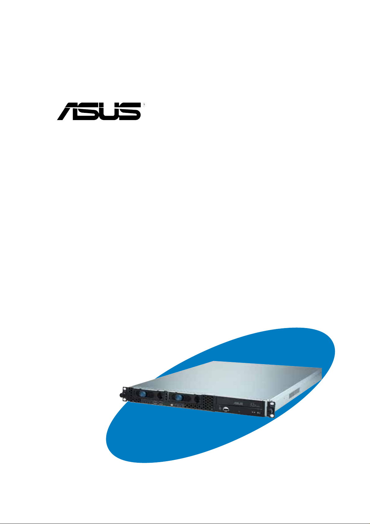
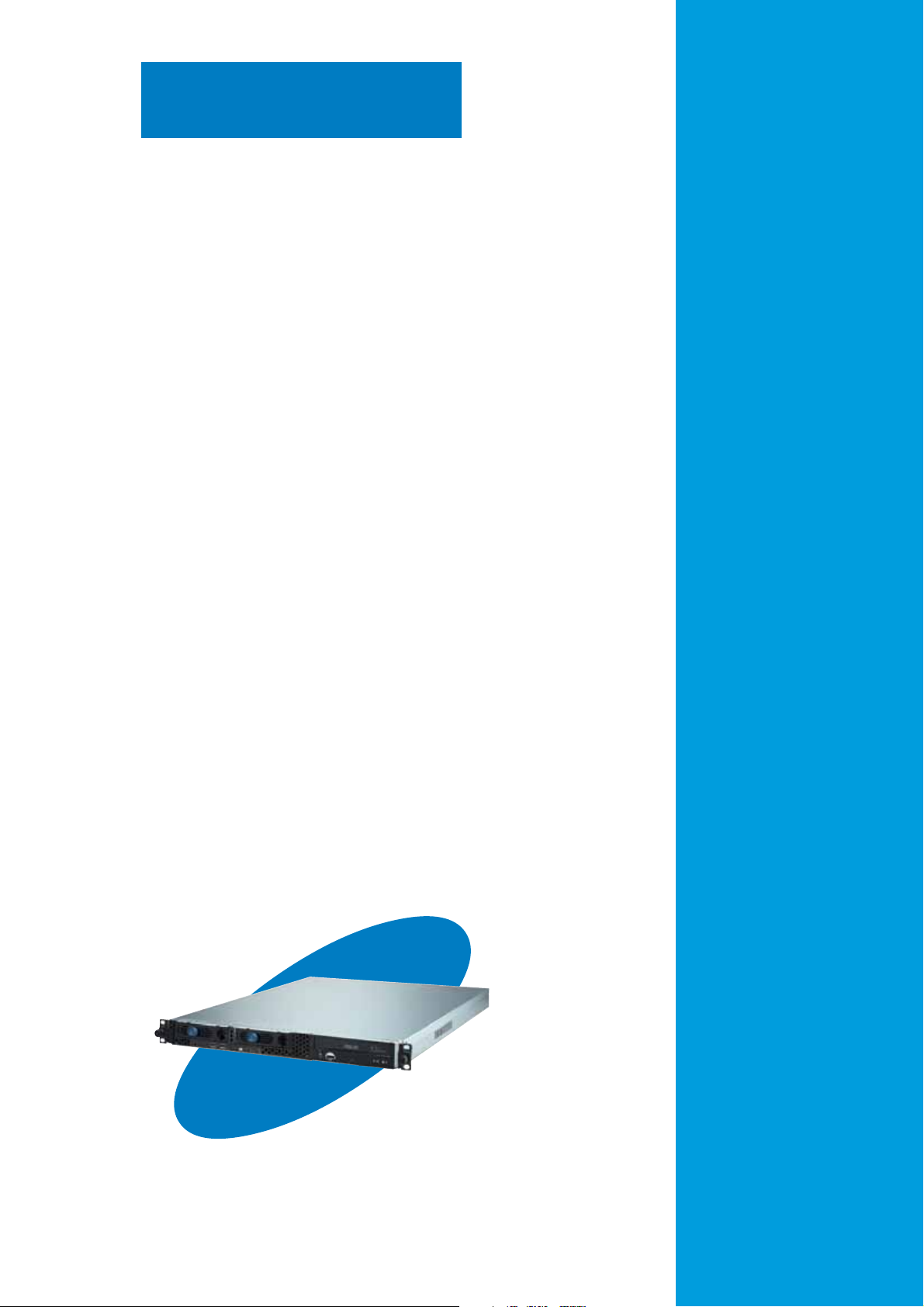
ASUS R10-A2P4 1U rackmount chassis kit
Product introduction
1-1
Page 8
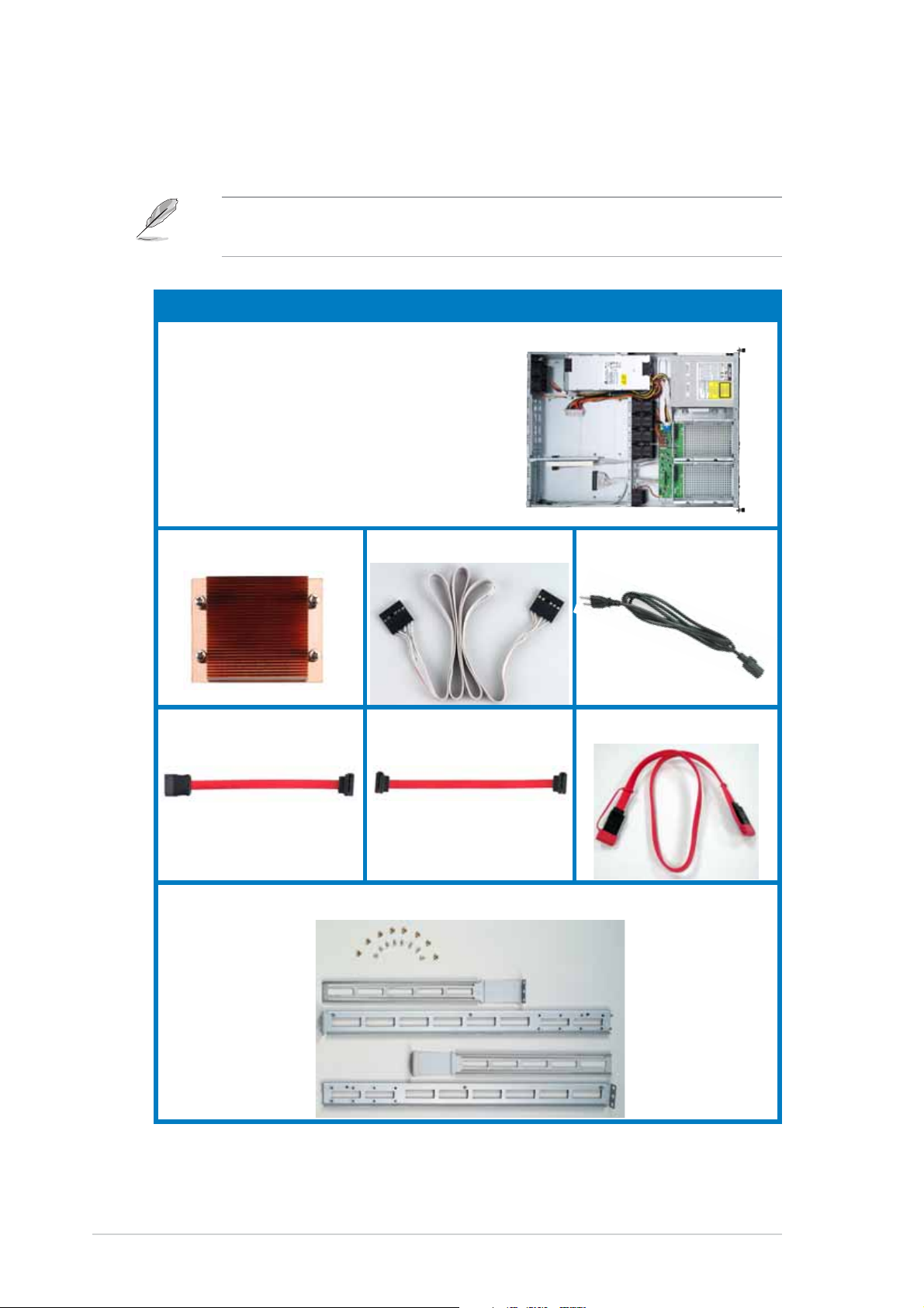
1.1 System package contents
Check your ASUS R10-A2P4 package for the following items.
Contact your dealer immediately if any of the items is damaged or
missing.
Package items
ASUS R10-A2P4 1U rackmount chassis
with:
• 300W/400W/500W power supply
• Optical drive
• System/device/rear fans
• 2 x HDD trays
• Riser card bracket
• SATA backplane
CPU heatsink AC power cord
SATA cable-1 SATA cable-2
SMBus cable
SATA cable-3
Rackmount rail kit
1-2
Chapter 1: Product introduction
Page 9
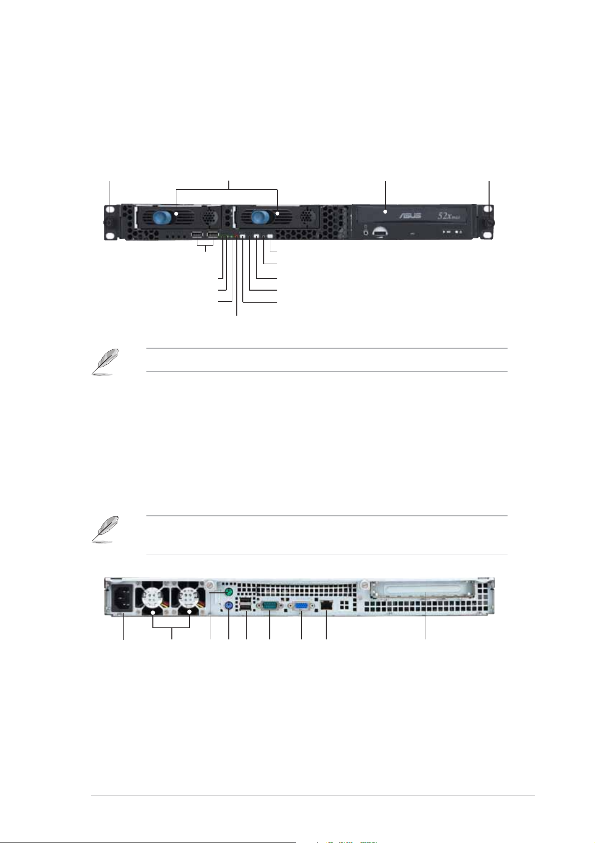
1.2 Front panel features
The chassis kit displays a simple yet stylish front panel with easily
accessible features. The power and reset buttons, LED indicators, location
switch, optical drive, and two USB ports are located on the front panel.
Rack screw Rack screw
USB ports
HDD Access LED
LAN2 LED
LAN1 LED
Refer to section “1.5.1 Front panel LEDs” for the LED descriptions.
HDD bays
Power button
Power LED
Location switch
Location LED
Reset button
Message LED
CD-ROM drive
1.3 Rear panel features
The rear panel includes the expansion slot, system power socket, and rear
fans. The middle part includes the I/O shield with openings for the rear
panel connectors on the motherboard.
The ports for the PS/2 keyboard, PS/2 mouse, USB, VGA, and Gigabit
LAN do not appear on the rear panel if motherboard is not present.
AC power socket
Rear fans
PS/2 mouse port
USB ports
PS/2 keyboard port
Serial port
VGA port
LAN port
Expansion slot
ASUS R10-A2P4 1U rackmount chassis kit
1-3
Page 10
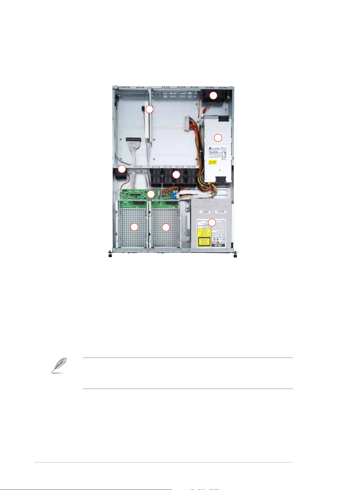
1.4 Internal features
The chaais includes the basic components as shown.
2
1
3
4
6
7
1. PCI-X riser card bracket
2. Rear fans
3. Power supply
4. Device fan
5. System fans
5
9
8
6. SATA backplane
7. HDD tray 1
8. HDD tray 2
9. Optical drive
1-4
The chassis kit does not include a floppy disk drive. Connect an
external floppy disk drive (USB interface) to any of the USB ports on
the front or rear panel if you need to use a floppy disk.
Chapter 1: Product introduction
Page 11
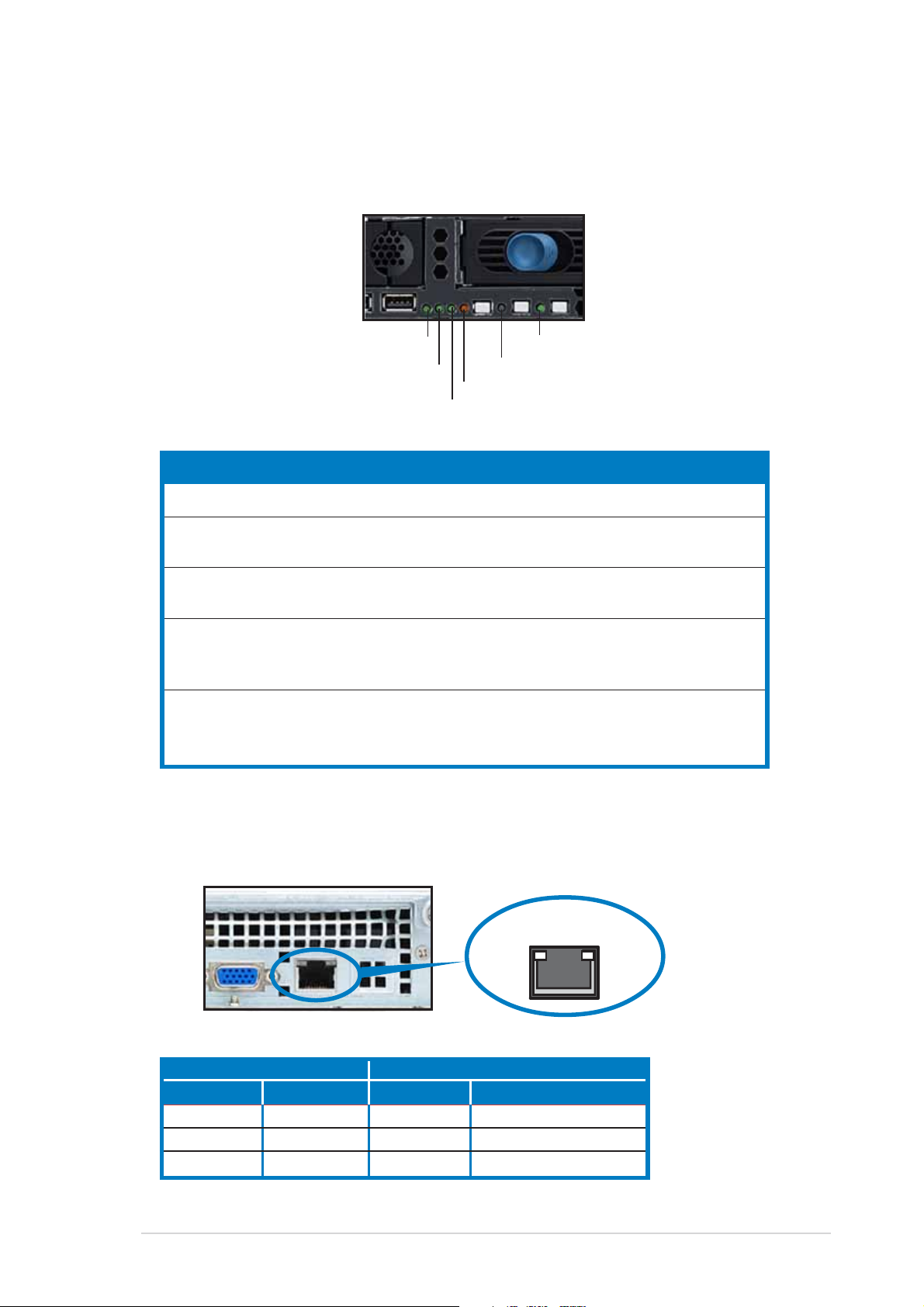
1.5 LED information
1.5.1 Front panel LEDs
HDD Access LED
LAN2 LED
Message LED
LAN1 LED
LED Display status Description
Power LED ON System power ON
HDD Access LED OFF No activity
Blinking Read/write data into the HDD
Message LED OFF System is normal; no incoming event
Blinking ASWM indicates a HW monitor event
Location LED OFF Normal status
ON Location switch is pressed
(Press the location switch again to turn off)
LAN LED OFF No LAN connection
Blinking LAN is transmitting or receiving data
ON LAN connection is present
Power LED
Location LED
1.5.2 Rear panel LEDs
RJ-45
ACT/LINK LED SPEED LED
Status Description Status Description
OFF No link OFF 10Mbps connection
Green Linked Orange 100Mbps connection
Blinking Linking Green 1000Mbps connection
ASUS R10-A2P4 1U rackmount chassis kit
SPEEDACT/LNK
1-5
Page 12

1-6
Chapter 1: Product introduction
Page 13

Chapter 2
This chapter lists the hardware setup
procedures that you have to perform when
installing or removing system components.
ASUS R10-A2P4 1U rackmount chassis kit
Hardware setup
2-1
Page 14

2.1 Preparation
Before proceeding, prepare everything that you might need to facilitate
installation.
2.1.1 Tools to use
1. Phillips head screw driver
2. Flat head screw driver
2.1.2 System components and devices to install
The following items are the basics that you need to install into the chassis
kit. You may need to install other devices depending on your configuration.
1. Motherboard
2. Hard disk drives
3. Drive cables
4. PCI-X add-on card
2-2
Chapter 2: Hardware setup
Page 15

2.2 Removing and installing the chassis cover
2.2.1 Removing the cover
1. Use a Phillips screwdriver to remove the screw on each front end of
the top cover.
Thumbscrews
2. Loosen the two thumbscrews on
the rear panel to release the top
cover from the chassis.
3. Firmly hold the cover and slide it
toward the rear panel for about
half an inch until it is disengaged
from the chassis.
4. Lift the cover from the chassis.
1/2 inch distance
ASUS R10-A2P4 1U rackmount chassis kit
2-3
Page 16

2.2.2 Installing the cover
1. Position the cover on top of the chassis with the thumbscrews on the
rear, and leaving a gap of about half an inch from the front panel.
Side markings
2. Make sure that the side markings on the cover (two on each side) are
aligned to the grooves on the chassis.
3. Slide the cover toward the front until it snaps in place.
4. Tighten the thumbscrews on the rear to secure the cover.
Thumbscrews
2-4
Chapter 2: Hardware setup
Grooves
Page 17

2.3 Motherboard installation
This section only describes how to install a supported motherboard into
the R10-A2P4 chassis kit. Refer to the motherboard user guide for
instructions on installing specific motherboard components.
2.3.1 Motherboard dimensions
This chassis kit supports an ASUS motherboard that measures 12 x 10.5
inches (30.48 x 26.67 cm). Motherboards of smaller sizes will fit into the
chassis. Refer to the motherboard user guide for more information on the
motherboard dimension and other system requirements.
Make sure that the motherboard you intend to install to the chassis
does not exceed the maximum specified dimensions. Otherwise, it will
not fit into the chassis.
ASUS R10-A2P4 1U rackmount chassis kit
2-5
Page 18

2.3.2 Placement direction and screw holes
Align the holes on the motherboard (indicated by white circles in the
picture below) to the corresponding standoffs on the motherboard metal
plate inside the chassis.
Place screws through the designated holes to secure the motherboard to
the chassis. Refer to the motherboard user guide for the specific number
of screws that you need to use.
Place this side (with I/O ports)
to the rear side of the chassis
The following figure shows the specific locations of the standoffs (indicated
by black circles) inside the chassis. These standoffs should match with the
holes on the motherboard as pointed out above.
2-6
Chapter 2: Hardware setup
Page 19

2.3.3 Installing the motherboard
To install the motherboard:
1. Firmly hold the riser card bracket,
then pull it up to detach it from the
chassis.
2. Clear the motherboard area by
re-routing the pre-connected
cables to facilitate the
motherboard installation.
3. Firmly hold the motherboard as
shown, and place the side with
the CPU sockets near the system
fans.
CPU sockets
ASUS R10-A2P4 1U rackmount chassis kit
2-7
Page 20

4. Fit the rear panel connectors to
the I/O shield openings on the
chassis rear.
5. Match the motherboard holes with
the chassis standoffs.
6. Secure the motherboard with
screws. Refer to the motherboard
user guide for the specific number
of screws that you need to use.
The chassis appears as shown
with the motherboard installed.
Refer to the motherboard user guide for instructions on installing CPU,
heatsink, and system memory.
2-8
Chapter 2: Hardware setup
Page 21

2.4 Hard disk drives
To install a SATA HDD:
1. Release a drive tray by pushing
the spring lock to the right, then
pulling the tray lever outward. The
drive tray ejects slightly after you
pull out the lever.
2. Firmly hold the tray lever and pull
the drive tray out of the bay.
3. Take note of the drive tray holes.
Each side has three holes to fit
different types of hard disk drives.
Use two screws on each side to
secure the hard disk drive.
4. Place a SATA hard disk drive on
the tray, then secure it with four
screws.
ASUS R10-A2P4 1U rackmount chassis kit
2-9
Page 22

5. Carefully insert the drive tray and
push it all the way to the depth of
the bay until just a small fraction
of the tray edge protrudes.
When installed, the SATA connector on the drive connects to the SATA
interface on the backplane.
SATA interface
on the backplane
6. Push the tray lever until it clicks,
and secures the drive tray in
place. The drive tray is correctly
placed when its front edge aligns
with the bay edge.
7. Repeat steps 1 to 6 if you wish to
install a second SATA drive.
8. Connect the bundled SATA cables to the connectors on the SATA
backplane. Refer to section “2.7 SATA backplane cabling” for
information on the SATA backplane cable connections.
2-10
Chapter 2: Hardware setup
Page 23

2.5 Expansion slot
The chassis comes with a riser card bracket. You need to remove the
bracket if you wish to install an PCI-X expansion card.
To install a PCI-X card:
1. Firmly hold a riser card bracket,
then pull it up to detach it from the
PCI-X slot on the motherboard.
Install a motherboard
following the steps in section
“2.3.3 Installing a
motherboard.”
2. Use a Phillips (cross) screwdriver
to remove the screw that secures
the slot metal cover.
3. Install a PCI-X card to the bracket
as shown, then secure the card
with a screw.
4. Take note of the holes on the riser
card bay. The two pegs on the
riser card bracket should match
these holes to ensure that the
bracket is properly in place.
Peg on the riser
card bracket
ASUS R10-A2P4 1U rackmount chassis kit
2-11
Page 24

4. Install the riser card bracket with
the card into the PCI-X slot on the
motherboard.
5. Make sure that the golden
connectors completely fit the slot
and the bracket aligns with the
rear panel.
6. Connect the cable(s) to the card,
if applicable.
2-12
Chapter 2: Hardware setup
Page 25

2.6 Removable components
You may need to remove previously installed system components when
installing or removing system devices, or when you need to replace
defective components. This section tells how to remove the following
components:
1. System fans
2. Device fan
3. Power supply module
4. Optical drive
5. Motherboard
2.6.1 System fans
To uninstall the system fans:
1. Disconnect all the system fan
cables from the connectors on the
backplane board.
2. Remove the four screws that
secure a fan.
3. Repeat step 2 to uninstall the
other fans.
2.6.2 Device fan
To uninstall the device fan:
1. Disconnect the system fan cable from
the connector on the motherboard.
2. Remove the four screws that secure
the device fan.
Fan screw
ASUS R10-A2P4 1U rackmount chassis kit
Fan screw
2-13
Page 26

2.6.3 Power supply module
To uninstall the power supply module:
1. Disconnect all the power cables
connected to the motherboard and
other system devices.
2. Use a Phillips (cross) screwdriver
to remove the screw the secures
the front end of the power supply.
3. Slide the power supply backward for about half an inch, then carefully
lift it out from the chassis.
2-14
Chapter 2: Hardware setup
Page 27

2.6.4 Optical drive
To uninstall the optical drive:
1. Disconnect the power and signal
cables connected to the rear of
the optical drive.
2. Use a Phillips (cross) screwdriver
to remove the two screws that
secure the meal bracket on the
side of the optical drive. Remove
the bracket to release the drive.
3. Slide the optical drive toward the
front panel, then carefully pull it
out of the drive bay.
ASUS R10-A2P4 1U rackmount chassis kit
2-15
Page 28

To install an optical drive:
1. From the front panel, insert the
rear end of the optical drive into
the 5.25-inch drive bay.
2. Place the metal bracket parallel to the side of the optical drive,
matching its two pegs with the lower holes, and the bracket holes with
the standoffs on the base of the chassis.
The metal bracket should fit completely to ensure that the optical drive
is securely in place.
Drive holes to match the
pegs on the metal bracket
Standoffs to match the
holes on the metal bracket
3. Secure the bracket with two
screws.
Drive metal bracket
Bracket pegs
Holes to match the standoffs
2-16
Chapter 2: Hardware setup
Page 29

2.6.5 Motherboard
To uninstall the motherboard:
1. Disconnect all the power and signal cables connected to the
motherboard.
2. Uninstall all the devices from the motherboard including the CPU and
heatsink, riser card brackets, and DDR DIMMs. Refer to the
corresponding sections for instructions on removing these
components.
3. Use a Phillips (cross) screwdriver to remove the screws that secure the
motherboard to the base of the chassis. Refer to the section “2.3.2
Placement direction and screw holes” for information.
4. Carefully lift the motherboard out of the chassis.
ASUS R10-A2P4 1U rackmount chassis kit
2-17
Page 30

2.7 SATA backplane cabling
Connects the SMBus
cable from the MB
Connect the SA TA
cables from the MB
(FAN1) Connects the fan cable
from CPU_FAN1 on the MB
Connect the system
fan cables
Connect the SATA HDDs
Connects a 4-pin plug
from power supply
2-18
Ensure that the FAN1 connector on the SATA backplane and the
CPU_FAN2 on the motherboard are connected via the 3-pin fan cable.
The fan RPM (rotations per minute) are monitored and automatically
adjusted through this feature.
Chapter 2: Hardware setup
Page 31

Chapter 3
This chapter tells how to install the system
to a rack.
ASUS R10-A2P4 1U rackmount chassis kit
Rackmounting
2-1
Page 32

3.1 Rackmount rail kit items
If you have the rackmount rail kit, it contains two pairs of rails (one pair for
each side of the barebone system), and eight (8) pairs of nut-and-bolt type
screws.
Nuts
Bolts
Left pair
Right pair
3.2 Rack rails assembly
To assemble the rack rails:
1. Determine the depth of the rack where you wish to install the system.
2. Match one long and one short rail to your desired length, and fix them
together using four (4) pairs of nuts and bolts.
3. Repeat step 2 to assemble the other rail pair.
Rear ends
Bolts on inner side
Nuts on outer side
3-2
Front ends
Chapter 3: Rackmounting
Page 33

3.3 Attaching the rails to the rack
To attach the rails to the rack:
1. Select one unit of space (1U) on the
rack where you wish to install the
barebone server.
2. Remove the screws from the 1U space
on the rack front.
3. Align the front end holes of a rack rail
pair to the 1U space.
4. Drive in two screws on the outer holes
to secure the front end.
1U space
5. Find the rear 1U space that corresponds to the front 1U space where
you attached the rail.
6. Remove the screws from the rear 1U space, and align the rear end
holes.
7. Drive in two screws on the outer holes to secure the rear end.
8. From the rack front, find the corresponding 1U space for the second
rail pair.
9. Repeat steps 2 to 7 to attach the second rail pair. When properly
installed, the rack rails appear as shown.
ASUS R10-A2P4 1U rackmount chassis kit
3-3
Page 34

3.4 Rackmounting the server
To mount the server to the rack:
1. Firmly hold the server on both sides and insert the rear panel side to
the front end of the rack rail, then carefully push the server all the way
to the back until the front panel fits the front end of the rack, and the
rack screws on the server match the middle hole on the rack..
2. Tighten the two rack screws to secure
the server to the rack.
3-4
Rack screw
Chapter 3: Rackmounting
 Loading...