


Q370M-IM-A
Industrial Motherboard

E17522
Second Edition
October 2020
Copyright © 2020 ASUSTeK COMPUTER INC. All Rights Reserved.
No part of this manual, including the products and software described in it, may be reproduced,
transmitted, transcribed, stored in a retrieval system, or translated into any language in any form or by any
means, except documentation kept by the purchaser for backup purposes, without the express written
permission of ASUSTeK COMPUTER INC. (“ASUS”).
Product warranty or service will not be extended if: (1) the product is repaired, modied or altered, unless
such repair, modication of alteration is authorized in writing by ASUS; or (2) the serial number of the
product is defaced or missing.
ASUS PROVIDES THIS MANUAL “AS IS” WITHOUT WARRANTY OF ANY KIND, EITHER EXPRESS
OR IMPLIED, INCLUDING BUT NOT LIMITED TO THE IMPLIED WARRANTIES OR CONDITIONS OF
MERCHANTABILITY OR FITNESS FOR A PARTICULAR PURPOSE. IN NO EVENT SHALL ASUS, ITS
DIRECTORS, OFFICERS, EMPLOYEES OR AGENTS BE LIABLE FOR ANY INDIRECT, SPECIAL,
INCIDENTAL, OR CONSEQUENTIAL DAMAGES (INCLUDING DAMAGES FOR LOSS OF PROFITS,
LOSS OF BUSINESS, LOSS OF USE OR DATA, INTERRUPTION OF BUSINESS AND THE LIKE),
EVEN IF ASUS HAS BEEN ADVISED OF THE POSSIBILITY OF SUCH DAMAGES ARISING FROM ANY
DEFECT OR ERROR IN THIS MANUAL OR PRODUCT.
SPECIFICATIONS AND INFORMATION CONTAINED IN THIS MANUAL ARE FURNISHED FOR
INFORMATIONAL USE ONLY, AND ARE SUBJECT TO CHANGE AT ANY TIME WITHOUT NOTICE,
AND SHOULD NOT BE CONSTRUED AS A COMMITMENT BY ASUS. ASUS ASSUMES NO
RESPONSIBILITY OR LIABILITY FOR ANY ERRORS OR INACCURACIES THAT MAY APPEAR IN THIS
MANUAL, INCLUDING THE PRODUCTS AND SOFTWARE DESCRIBED IN IT.
Products and corporate names appearing in this manual may or may not be registered trademarks or
copyrights of their respective companies, and are used only for identication or explanation and to the
owners’ benet, without intent to infringe.
ii

Contents
Chapter 1 Product overview
1.1 Package contents ......................................................................... 1-1
1.2 Features ........................................................................................ 1-1
1.3 Specications ............................................................................... 1-2
Chapter 2 Motherboard information
2.1 Before you proceed ..................................................................... 2-1
2.2 Motherboard layout ...................................................................... 2-2
2.3 Central Processing Unit (CPU) ................................................... 2-4
2.3.1 Installing the CPU ........................................................... 2-5
2.3.2 CPU heatsink and fan assembly installation ................... 2-7
2.4 System memory ........................................................................... 2-9
2.5 Jumpers ...................................................................................... 2-10
2.6 Connectors ................................................................................. 2-12
2.6.1 Rear panel connectors .................................................. 2-12
2.6.2 Internal connectors ....................................................... 2-14
Chapter 3 BIOS setup
3.1 BIOS setup program .................................................................... 3-1
3.1.1 BIOS menu screen .......................................................... 3-2
3.2 Main menu .................................................................................... 3-2
3.2.1 System Language [English] ............................................ 3-2
3.2.2 System Date [Day MM/DD/YYYY] .................................. 3-2
3.2.3 System Time [HH:MM:SS] .............................................. 3-2
3.2.4 Security ........................................................................... 3-2
3.3 Ai Tweaker menu .......................................................................... 3-4
3.3.1 CPU Power Enhancement .............................................. 3-4
3.3.2 CPU Core Ratio .............................................................. 3-4
3.3.3 DRAM Odd Ratio Mode .................................................. 3-5
3.3.4 DRAM Frequency ........................................................... 3-5
3.3.5 Power-saving & Performance Mode ............................... 3-6
3.3.6 DRAM Timing Control ..................................................... 3-6
3.3.7 DIGI+ VRM .................................................................... 3-14
3.3.8 Internal CPU Power Management ................................ 3-15
3.3.9 CPU Core/Cache Current Limit Max. ............................ 3-15
3.3.10 CPU Graphics Current Limit ......................................... 3-16
iii

3.3.11 Min. CPU Cache Ratio .................................................. 3-16
3.3.12 Max. CPU Cache Ratio ................................................. 3-16
3.3.13 Max. CPU Graphics Ratio ............................................. 3-16
3.3.14 DRAM Voltage .............................................................. 3-16
3.3.15 DRAM REF Voltage Control ......................................... 3-16
3.4 Advanced menu ......................................................................... 3-18
3.4.1 Platform Misc Conguration .......................................... 3-18
3.4.2 CPU Conguration ........................................................ 3-19
3.4.3 System Agent (SA) Conguration ................................. 3-21
3.4.4 PCH Conguration ........................................................ 3-22
3.4.5 PCH Storage Conguration .......................................... 3-22
3.4.6 PCH-FW Conguration ................................................. 3-23
3.4.7 AMT Conguration ........................................................ 3-23
3.4.8 Trusted Computing ....................................................... 3-24
3.4.9 Onboard Devices Conguration .................................... 3-25
3.4.10 APM Conguration ........................................................ 3-27
3.4.11 Serial Port Console Redirection .................................... 3-27
3.4.12 Intel TXT Information ................................................... 3-28
3.4.13 PCI Subsystem Settings ............................................... 3-28
3.4.14 USB Conguration ........................................................ 3-28
3.4.15 Network Stack Conguration ........................................ 3-29
3.4.16 NVMe Conguration ...................................................... 3-29
3.4.17 HDD Secure Erase ....................................................... 3-29
3.4.18 HDD/SSD SMART Information ..................................... 3-29
3.5 Monitor menu ............................................................................. 3-30
3.6 Boot menu .................................................................................. 3-34
3.7 Tool menu ................................................................................... 3-38
3.8 Exit menu .................................................................................... 3-39
Appendix
Notices .......................................................................................................A-1
ASUS contact information .......................................................................A-5
iv
Chapter 1
Product overview
1.1 Package contents
Check your industrial motherboard package for the following items.
1 x ASUS Q370M-IM-A Motherboard
2 x Serial ATA 6.0 Gb/s cables
1 x ASUS I/O Shield
NOTE: If any of the above items is damaged or missing, contact your
distributor or sales representative immediately.
1.2 Features
• Intel® socket 1151 for 9th/8th Gen Intel® Core™ i9/ i7/ i5/ i3, Pentium®, and
Celeron® processors
• Four Dual Channel DDR4 2666/2400/2133MHz Non-ECC U-DIMMs up to
64GB
• 6 x SATA 6.0 Gb/s, 4 x USB 3.2 Gen 2, 4 x USB 3.2 Gen 1, 4 x USB 2.0 ports
• 1 x PCIe x16 slot, 2 x PCIe x1 slots, 1 x PCI slot, 1 x M.2 (Key E, 2230) for WiFi devices, 1 x M.2 supports PCIe and SATA modes, 1 x M.2 supports PCIe
mode
• Multi-display: 2 x DisplayPort, 1 x HDMI, 1 x D-Sub
Chapter 1: General information
1-1
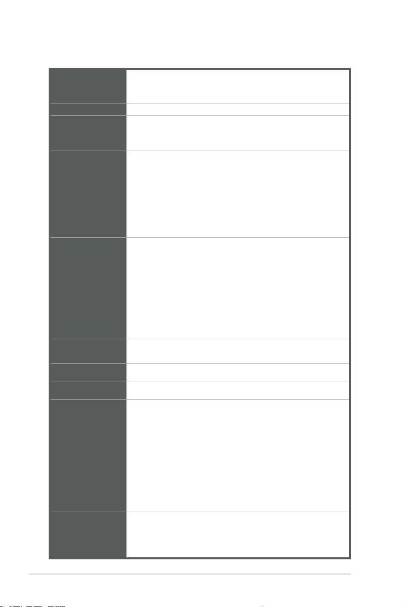
1.3 Specications
Intel® socket 1151 for 9th/8th Gen Intel® Core™ i9/ i7/ i5/ i3,
CPU
Chipset Intel® Q370 Chipset
Memory
Graphics
Expansion slots
Storage
LAN Intel® I219LM Gigabit LAN controller
Pentium®, and Celeron® processors
Supports Intel® 14nm CPU
4 x U-DIMM, max.64GB, DDR4 2666*/2400/2133 MHz
* DDR4 2666MHz and higher memory modules will run at max.
2666MHz on Intel® 9th/8th Gen. 6-core or higher processors
Intel® UHD Graphics 630/610
Multi-VGA output support: DP/HDMI/D-Sub ports
- Supports HDMI 1.4 output with a maximum resolution of
4096 x 2304 @ 24Hz / 2560 x 1600 @ 60Hz
- Supports 2x DisplayPort outputs with a maximum resolution
of 4096 x 2304 @ 60 Hz
- Supports D-Sub output with a maximum resolution of 1920 x
1200 @ 60Hz
1 x PCI Express 3.0/2.0 x16 slot
2 x PCI Express 3.0/2.0 x1 slots
1 x PCI slot
1 x M.2 socket 1 (Key E, 2230) for WiFi devices
1 x M.2 socket 3 supports SATA* and PCIe x4 modes
1 x M.2 socket 3 supports PCIe x4 mode
Intel® OptaneTM Memory Ready
*SATA mode shares with SATA6G_2 port
- 6 x SATA 6.0 Gb/s ports
- Supports RAID 0, 1, 5, 10
Audio Realtek® ALC887 8-channel High Denition Audio CODEC
1 x P/S2 keyboard port (purple)
1 x P/S2 mouse port (green)
2 x DP connectors
Rear panel I/O
ports
Front panel I/O
ports
1-2
1 x HDMI port
1 x D-Sub port
4 x USB 3.2 Gen 2 ports
2 x USB 2.0 ports
1 x LAN (RJ45) port
3 x Audio jacks
2 x COM headers(2 x RS232)
2 x USB 3.2 Gen 1 connectors support additional 4 USB 3.2 Gen
1 ports
1 x USB 2.0 connector supports additional 2 USB 2.0 ports
(continued on the next page)
Q370M-IM-A
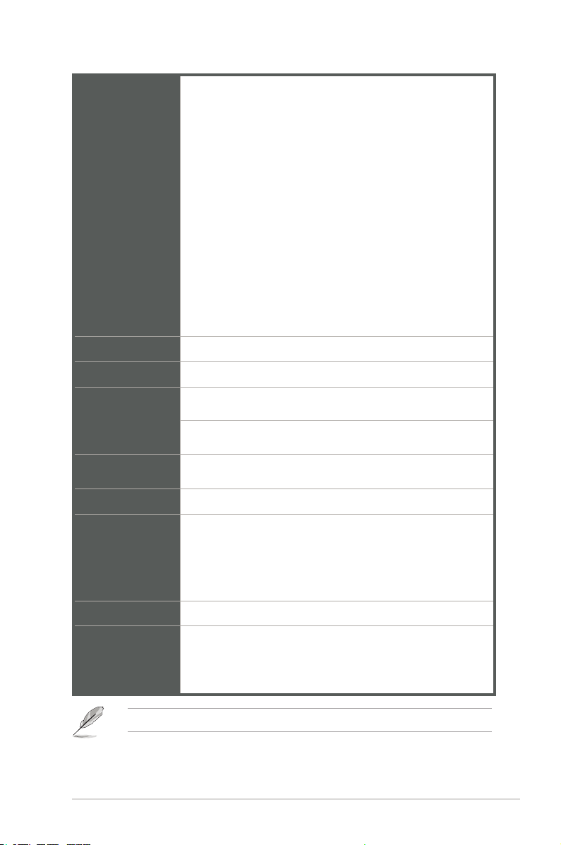
1 x CPU Fan connector
2 x Chassis Fan connectors
1 x Chassis intrusion header
1 x Front panel audio connector(AAFP)
1 x System panel connector
1 x Clear CMOS header
Front panel I/O
ports
Manageability
Watch dog timer NO
Power
requirement
Operation
Temperature
Non-Operation
Temperature
Relative Humidity 0%~85%
OS support
Form factor Micro ATX, 9.6 x 9.6 inches (24.4 x 24.4 cm)
Certication
1 x Speaker connector
1 x LPC Debug header
1 x LPT port header
1 x 24-pin ATX power connector
1 x 8-pin EATX power connector
6 x SATA 6.0Gb/s connectors
1 x MONO_out header
1 x DIS ME jumper
TPM IC 2.0 Onboard
WfM 2.0, DMI 2.0, WOL by PME
ATX Power
0~60°C
-40~85°C
Windows® 10 (64-bit)
Windows® 10 IoE Enterprise
Ubuntu
RedHat Enterprise
Fedora Workstation
CE
FCC
UL
CCC
NOTE: Specications are subject to change without notice.
Chapter 1: General information
1-3

1-4
Q370M-IM-A
Chapter 2
Motherboard information
2.1 Before you proceed
Take note of the following precautions before you install motherboard components
or change any motherboard settings.
CAUTION!
• Unplug the power cord from the wall socket before touching any
component.
• Before handling components, use a grounded wrist strap or touch a safely
grounded object or a metal object, such as the power supply case, to avoid
damaging them due to static electricity.
• Hold components by the edges to avoid touching the ICs on them.
• Whenever you uninstall any component, place it on a grounded antistatic
pad or in the bag that came with the component.
• Before you install or remove any component, always remove the AC power
by unplugging the power cord from the power outlet. Failure to do so may
cause severe damage to the motherboard, peripherals, or components.
Chapter 2: Motherboard information
2-1
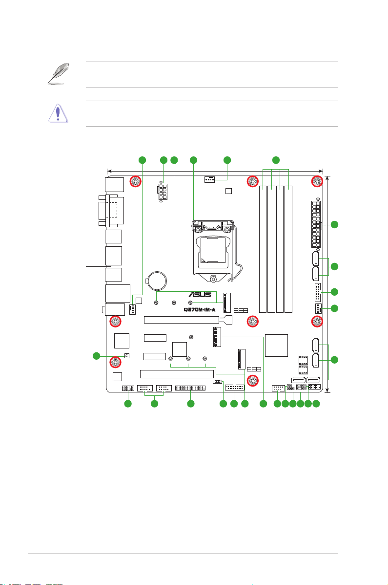
2.2 Motherboard layout
NOTE: Place eight screws into the holes indicated by circles to secure the
motherboard to the chassis.
CAUTION! Do not overtighten the screws! Doing so can damage the
motherboard.
Place this side
towards the rear
of the chassis
1 432 51
KBMS
VGA
HDMI
U32G2_12
DP12
U32G2_34
LAN_USB910
AUDIO
CHA_FAN1
Super
I/O
19
MONO_OUT
ALC
887
AAFP
EATX12V
BATTERY
®
Intel
I219LM
2280 2260 2242
PCIEX1_1
PCIEX1_2
COM1 COM2
24.4cm(9.6in)
PCIEX16
ASM
1083
2280 2260 2242
PCI
LPT
CPU_FAN
LGA1151
M.2(WIFI)
LPC_DEBUG
DIGI
+VRM
M.2_1(SOCKET3)
PCIE SATA IRST
M.2_1(SOCKET3)
X4 VV
U32G1_78
715 1416
DDR4 DIMM_B1 (64bit, 288-pin module)
DDR4 DIMM_B2* (64bit,288-pin module)
Intel
Q370
M.2_2(SOCKET3)
M.2_2(SOCKET3)
PCIE SATA IRST
X4 X V
USB1112
31718 13
1
2
EATXPWR
24.4cm(9.6in)
6
DDR4 DIMM_A1 (64bit, 288-pin module)
®
SATA6G_2 SATA6G_1
DDR4 DIMM_A2* (64bit, 288-pin module)
7
U32G1_56
1
CHA_FAN2
SATA6G_6 SATA6G_5
CLRTC
SPEAKER
DIS_ME
CHASSIS
128Mb
BIOS
64Mb
BIOS
SATA6G_4 SATA6G_3
F_PANEL
6
810 912 11
2-2
Q370M-IM-A
Connectors/Jumpers/Slots
1. CPU and chassis fan connectors (4-pin CPU_FAN, 4-pin CHA_FAN1/2) 2-16
2. ATX power connectors (24-pin EATXPWR, 8-pin EATX12V) 2-20
3. M.2 socket 3 2-18
4. Intel® LGA1151 CPU socket 2-4
5. DDR4 DIMM slots 2-9
6. SATA 6.0Gb/s connectors (7-pin SATA6G_1-6) 2-19
7. USB 3.2 Gen 1 connectors (U32G1_56; U32G1_78) 2-14
8. System panel connector (10-1 pin F_PANEL) 2-17
9. Speaker connector (4-1 pin SPEAKER) 2-16
10. Chassis Intrusion header (4-1 pin CHASSIS) 2-10
11. DIS_ME jumper (3-pin DIS_ME) 2-11
12. Clear RTC RAM (2-pin CLRTC) 2-10
13. USB 2.0 connector (10-1pin USB_1112) 2-15
14. M.2 Wi-Fi 2-18
15. LPC Debug header 2-19
16. LPT connector 2-14
17. Serial port connectors (10-1 pin COM1, COM2) 2-20
18. Front panel audio connector (10-1 pin AAFP) 2-21
19. Mono out header (2-pin Mono_Out) 2-15
Page
Chapter 2: Motherboard information
2-3
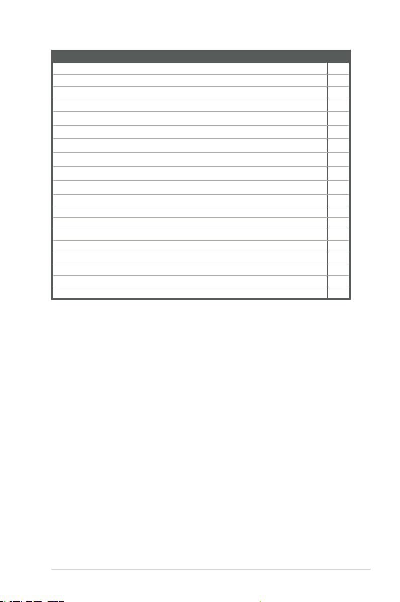
2.3 Central Processing Unit (CPU)
The motherboard comes with a surface mount LGA1151 socket designed for the
Intel® 9th/8th Generation Core™ i9 / i7 / i5 / i3, Pentium®, and Celeron® processors.
LGA1151
IMPORTANT: Unplug all power cables before installing the CPU.
CAUTION!
• Upon purchase of the motherboard, ensure that the PnP cap is on
the socket and the socket contacts are not bent. Contact your retailer
immediately if the PnP cap is missing, or if you see any damage to the
PnP cap/socket contacts/motherboard components. The manufacturer will
shoulder the cost of repair only if the damage is shipment/transit-related.
• Keep the cap after installing the motherboard. The manufacturer will
process Return Merchandise Authorization (RMA) requests only if the
motherboard comes with the cap on the LGA1151 socket.
• The product warranty does not cover damage to the socket contacts
resulting from incorrect CPU installation/removal, or misplacement/loss/
incorrect removal of the PnP cap.
2-4
Q370M-IM-A
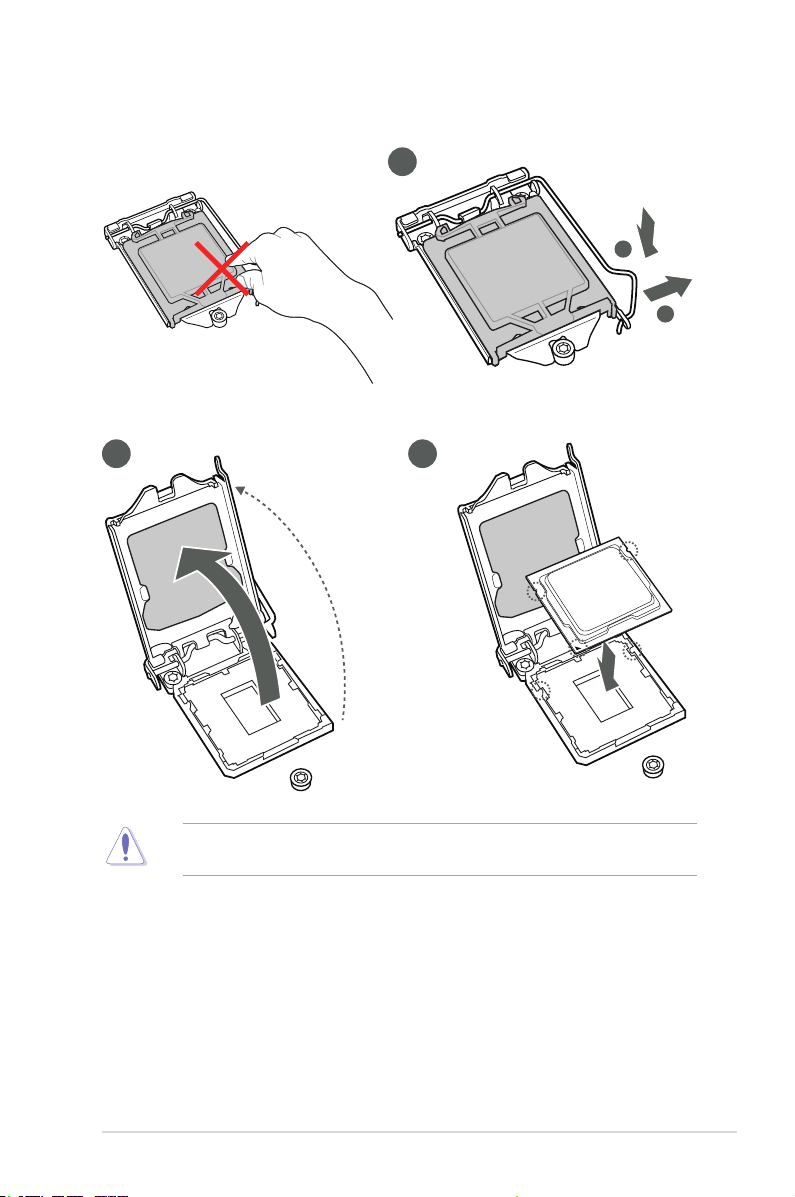
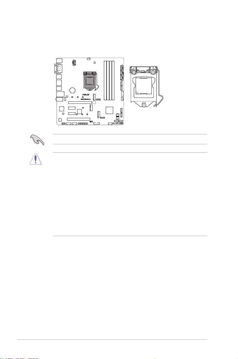
2.3.1 Installing the CPU
2 3
1
A
B
CAUTION! LGA1156 CPU is not compatible with the LGA1151 socket. DO
NOT install an LGA1156 CPU on the LGA1151 socket.
Chapter 2: Motherboard information
2-5
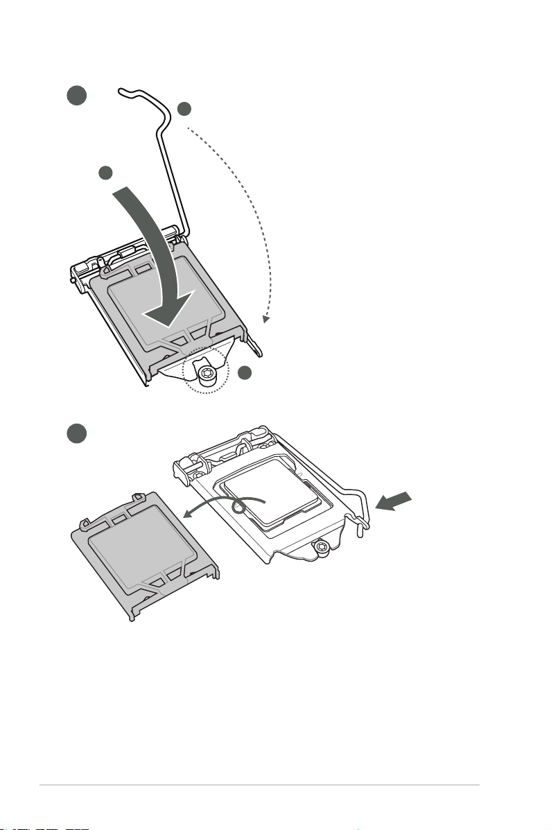
4
C
A
B
5
2-6
Q370M-IM-A
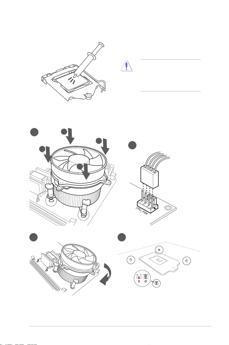
2.3.2 CPU heatsink and fan assembly installation
CAUTION! Apply the Thermal
Interface Material to the CPU
heatsink and CPU before you
install the heatsink and fan if
necessary.
To install the CPU heatsink and fan assembly
1
A
B
B
A
3 4
2
Chapter 2: Motherboard information
2-7
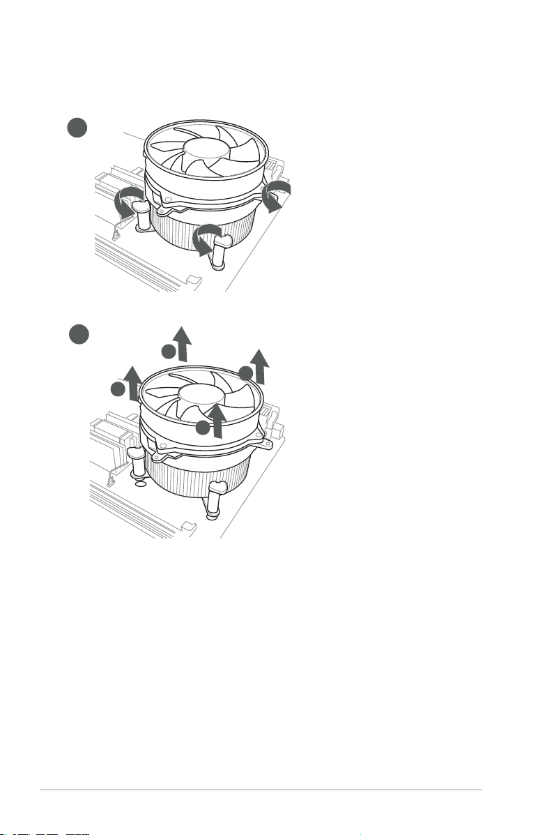
To uninstall the CPU heatsink and fan assembly
1
2
A
B
B
A
2-8
Q370M-IM-A
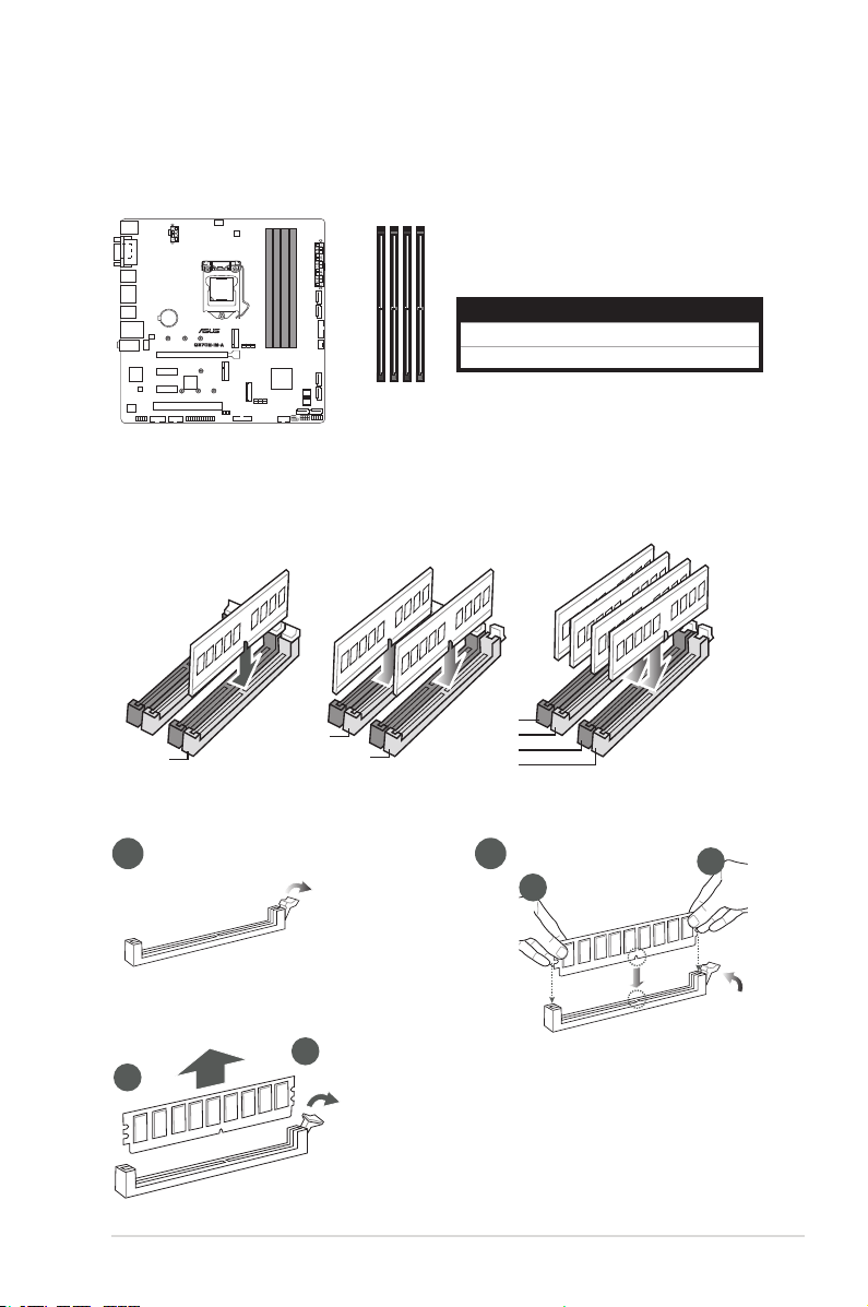
2.4 System memory
DIMM_A2*
This motherboard comes with four Double Data Rate 4 (DDR4) Dual Inline Memory Module
(DIMM) sockets. The gure below illustrates the location of the DDR4 DIMM sockets:
DIMM_B1
DIMM_B2*
Recommendedmemoryconguration
DIMM_B2*
DIMM_A2*
DIMM_A2*
Installing a DIMM
DIMM_A1
Channel Sockets
Channel A DIMM_A1 & DIMM_A2*
Channel B DIMM_B1 & DIMM_B2*
DIMM_B1
DIMM_B2*
DIMM_A1
DIMM_A2*
To remove a DIMM
A
B
Chapter 2: Motherboard information
21
A
B
2-9
2.5 Jumpers
1. Clear RTC RAM (2-pin CLRTC)
This header allows you to clear the CMOS RTC RAM data of the system
setup information such as date, time, and system passwords.
CLRTC
+3V_BAT
GND
PIN 1
Connector type
HEADER 1x2p, 2.54mm pitch, S/T
To erase the RTC RAM:
1. Turn OFF the computer and unplug the power cord.
2. Use a metal object such as a screwdriver to short the two pins.
3. Plug the power cord and turn ON the computer.
4. Hold down the <Del> key during the boot process and enter BIOS setup
to re-enter data.
NOTE: If the steps above do not help, remove the onboard battery and move
the jumper again to clear the CMOS RTC RAM data. After clearing the CMOS,
reinstall the battery.
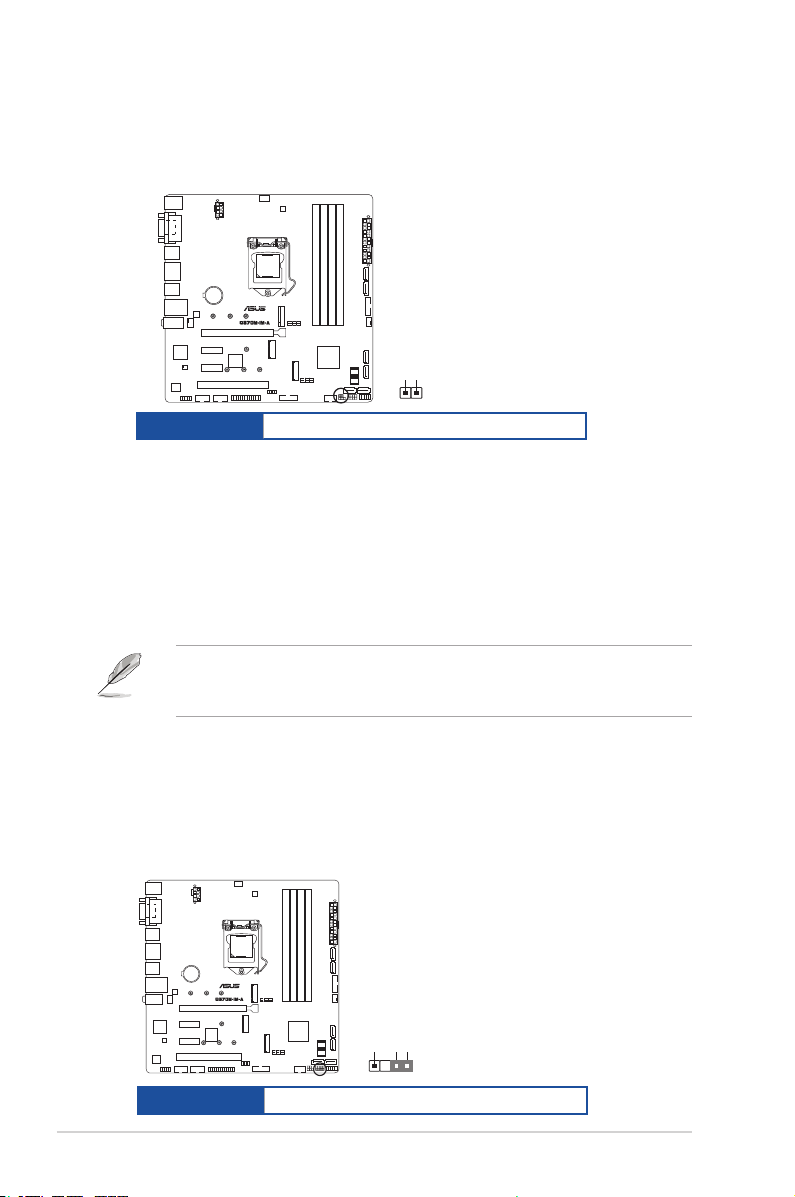
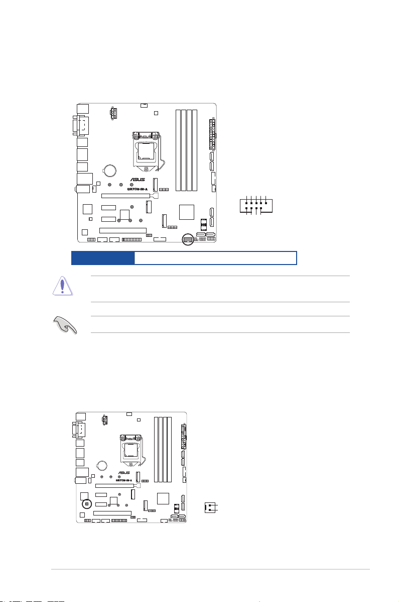
2. Chassis intrusion header (4-1 pin_CHASSIS)
This header is for a chassis-mounted intrusion detection sensor or switch. Connect
one end of the chassis intrusion sensor or switch cable to this connector. The
chassis intrusion sensor or switch sends a low-level signal to this connector
when a chassis component is installed. The signal is then generated as a chassis
intrusion event.
CHASSIS
2-10
Connector type
+5VSB_MB
Chassis Signal
GND
PIN 1
HEADER 4p, K2, 2.54mm pitch
Q370M-IM-A
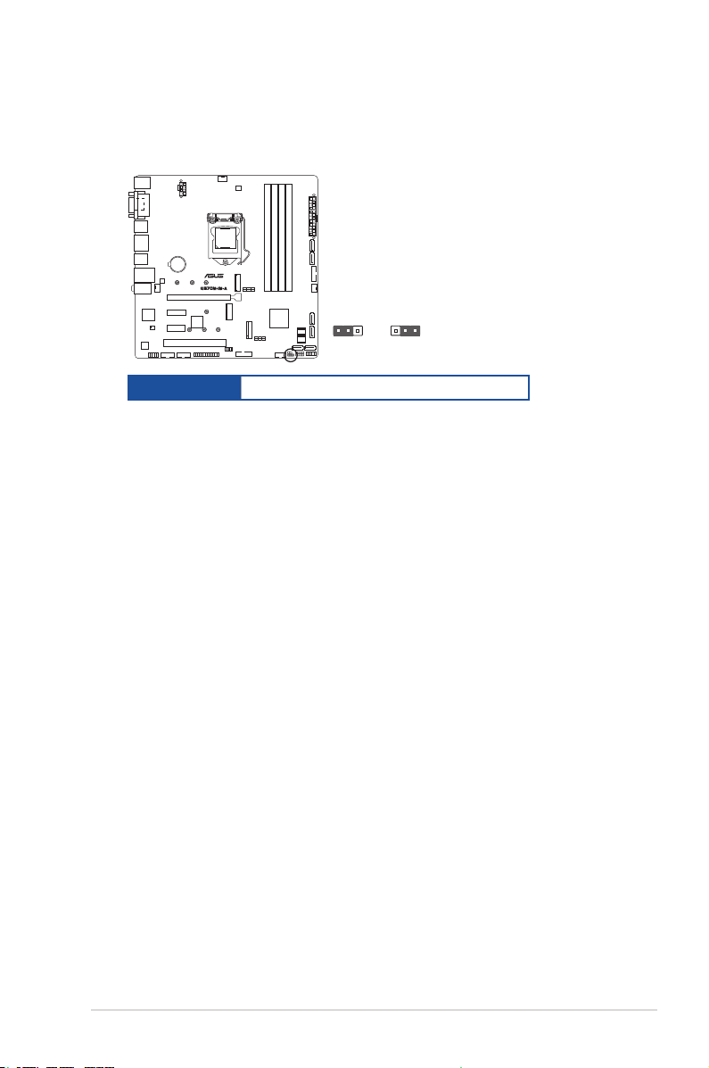
3. Intel® ME jumper (3-pin DIS_ME)
This jumper allows you to enable or disable the Intel® ME function. Set this
jumper to pins 1-2 to enable (default) the Intel® ME function and to pins 2-3 to
disable it.
DIS_ME
21
Normal
(Default)
2 3
Disable intel
ME function
Connector type
HEADER 1x3p, 2.54mm pitch, S/T
Chapter 2: Motherboard information
2-11
2.6 Connectors
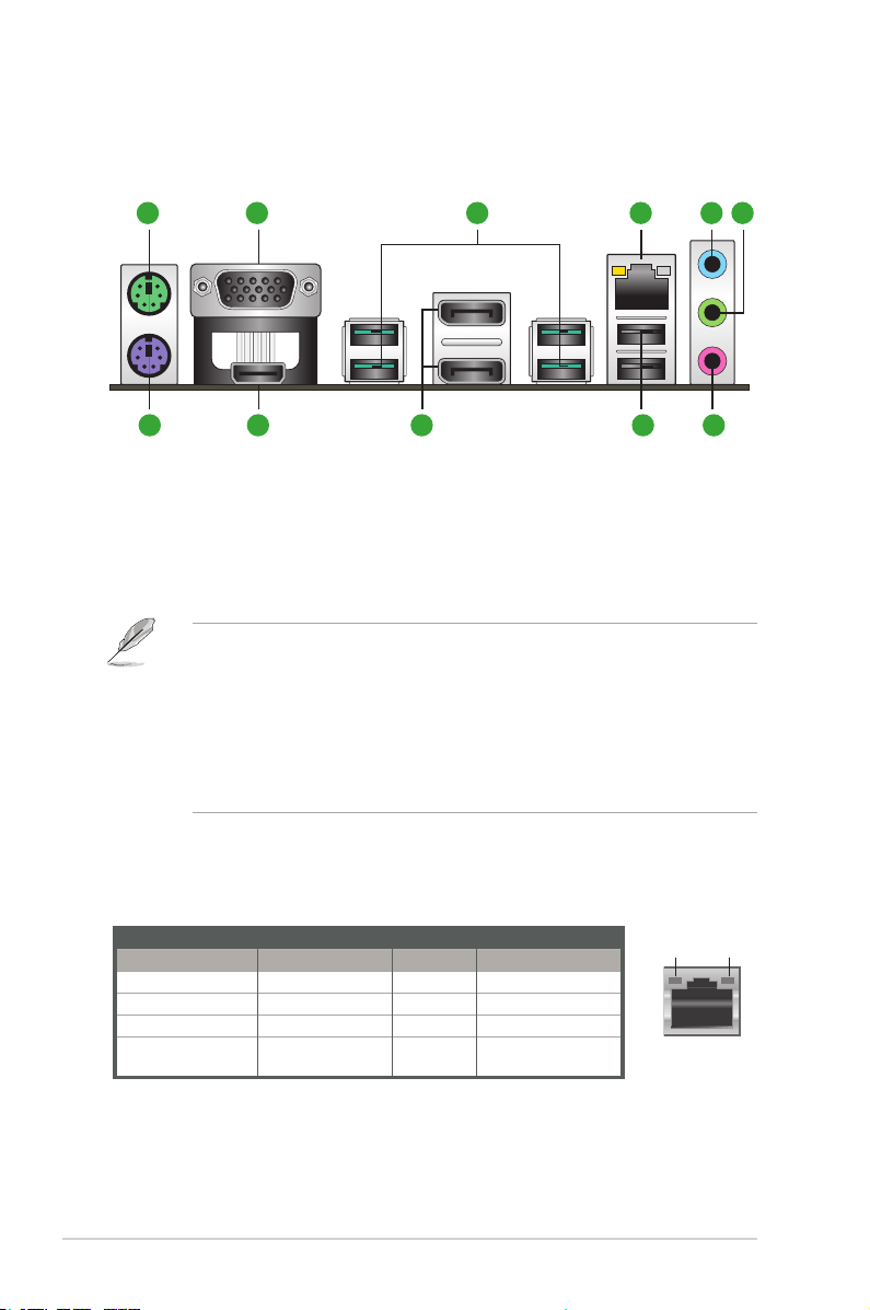
2.6.1 Rear panel connectors
1 2 3 4 5 6
7891011
1. PS/2 mouse port (green). This port is for a PS/2 mouse.
2. Video Graphics Adapter (VGA) port. This 15-pin port is for a VGA monitor
or other VGA-compatible devices.
3. USB 3.2 Gen 2 (up to 10Gbps) ports. These 9-pin Universal Serial Bus
(USB) ports are for USB 3.2 Gen 2 devices.
• USB 3.2 Gen 2 devices can only be used for data storage.
®
• Due to the design of the Intel
connected to the USB 2.0 and USB 3.2 Gen 2 ports are controlled by the
xHCI controller.
• We strongly recommend that you connect USB 3.2 Gen 2 devices to USB
3.2 Gen 2 ports for faster and better performance from your USB 3.2 Gen 2
devices.
4. LAN (RJ-45) ports. These ports allow Gigabit connection to a Local Area
Network (LAN) through a network hub.
LAN port LED indications
300 series series chipset, all USB devices
Activity/Link LED Speed LED
Status Description Status Description
Off No link OFF 10Mbps connection
Orange Linked ORANGE 100Mbps connection
Orange (Blinking) Data activity GREEN 1Gbps connection
Orange (Blinking
then steady)
2-12
Ready to wake up
from S5 mode
Activity Link
LED
LAN port
Q370M-IM-A
Speed
LED

5. Line In port (light blue). This port connects to the tape, CD, DVD player, or
other audio sources.
6. Line Out port (lime). This port connects to a headphone or a speaker. In the
4.1, and 5.1 channel congurations, the function of this port becomes Front
Speaker Out.
7. Microphone port (pink). This port connects to a microphone.
Refer to the audio conguration table for the function of the audio ports in 2.1,
4.1, 5.1, or 7.1-channel conguration.
8. USB 2.0 ports. These 4-pin Universal Serial Bus (USB) ports are for USB
2.0/1.1 devices.
9. DisplayPorts. These ports are for DisplayPort-compatible devices.
10. HDMI port. This port is for a High-Denition Multimedia Interface (HDMI)
connector, and is HDCP compliant allowing playback of HD DVD, Blu-ray,
and other protected content.
11. PS/2 keyboard port (purple). This port is for a PS/2 keyboard.
Chapter 2: Motherboard information
2-13
2.6.2 Internal connectors
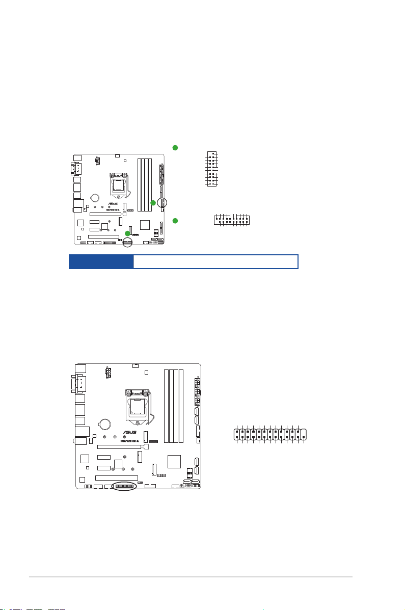
1. USB 3.2 Gen 1 connectors (20-1 pin U32G1_56; U32G1_78)
Connect a USB 3.2 Gen 1 module to any of these connectors for additional
USB 3.2 Gen 1 front or rear panel ports. These connectors comply with USB
3.2 Gen 1 specications and provide faster data transfer speeds of up to 5
Gbps, faster charging time for USB-chargeable devices, optimized power
efciency, and backward compatibility with USB 2.0.
A
U32G1_56
USB3+5V
IntA_P2_SSRX-
IntA_P2_SSRX+
IntA_P2_SSTXIntA_P2_SSTX+
IntA_P2_D-
IntA_P2_D+
PIN 1
USB3+5V
IntA_P1_SSRXIntA_P1_SSRX+
GND
GND
IntA_P1_SSTXIntA_P1_SSTX+
GND
GND
IntA_P1_DIntA_P1_D+
GND
Connector type
A
B
U32G1_78
B
BOX HD 2x10p, K20, 2.0mm pitch
Vbus
IntA_P1_SSRX-
IntA_P1_SSRX+
GND
IntA_P1_SSTX-
IntA_P1_SSTX+
GND
IntA_P1_D-
IntA_P1_D+
Vbus
IntA_P2_SSRX-
IntA_P2_SSRX+
GND
IntA_P2_SSTX-
IntA_P2_SSTX+
GND
GND
IntA_P2_D-
IntA_P2_D+
PIN 1
2. LPT connector (26-1pin LPT)
The LPT (Line Printing Terminal) connector supports devices such as a
printer. LPT standardizes as IEEE 1284, which is the parallel port interface
on IBM PC-compatible computers.
O_LPT_XAFD#_R
O_LPT_ERROR#_R
O_LPT_XINIT#_R
O_LPT_XSLIN#_R
GND
GND
GND
GND
GND
GND
GND
GND
LPT
PIN 1
O_LPT_PE_R
O_LPT_XPD0_R
O_LPT_XPD1_R
O_LPT_XPD2_R
O_LPT_XPD3_R
O_LPT_XPD4_R
O_LPT_XSTB#_R
O_LPT_XPD5_R
O_LPT_SLCT_R
O_LPT_XPD6_R
O_LPT_XPD7_R
O_LPT_ACK#_R
O_LPT_BUSY_R
2-14
Q370M-IM-A
3. USB 2.0 connector (10-1 pin USB1112)
This connector is for an USB 2.0 port. Connect the USB cable to this
connector. This USB connector complies with USB 2.0 specication that
supports up to 480 Mbps connection speed.
USB1112
USB+5V
USB_P11-
USB_P11+
GND
NC
Connector type
PIN 1
Header 2x5p, K9, 2.54mm pitch
USB+5V
USB_P12-
GND
USB_P12+
CAUTION! Never connect a 1394 cable to the USB connector. Doing so will
damage the motherboard.
NOTE: The USB cable is purchased separately.
4. MONO out header (2-pin MONO_OUT)
This internal mono out header allows connection to an internal, low power
speaker for basic system sound capability. You can connect a 3W speaker
to this header, but the subsystem is capable of driving a speaker load of 2
Ohms at 2 Watts (rms).
MONO_OUT
R_OUT+
R_OUT-
PIN 1
Chapter 2: Motherboard information
2-15
 Loading...