

Page 1
Service Manual PA246Q
RESTRICTIONS ON USE OF MATERIALS
:
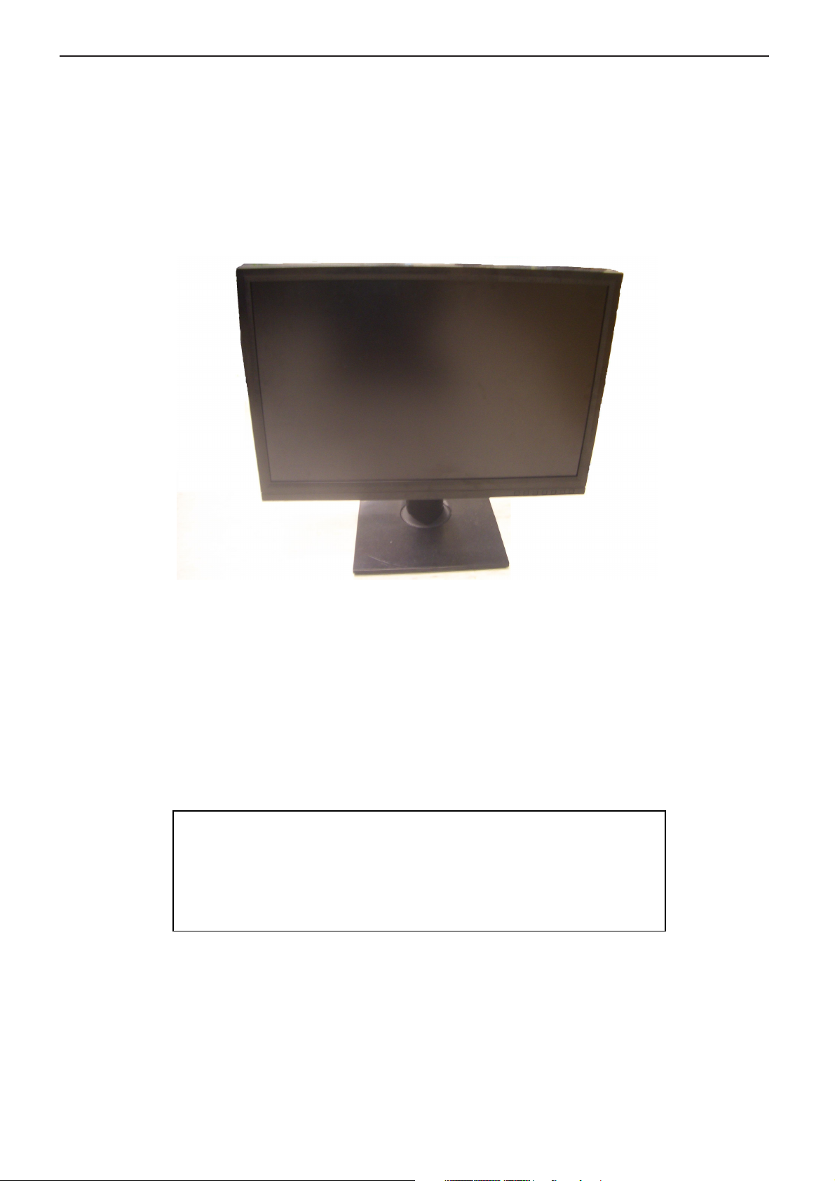
LCD Monitor Service Manual
Model: PA246Q
V 1.0
1
Page 2

Service Manual PA246Q
Important Safety Notice
Proper service and repair is important to the safe, reliable operation of all ASUS equipment. The service
procedures recommended by ASUS and described in this service manual are effective methods of performing
service operations. Some of these service operations require the use of tools specially designed for the purpose.
The special tools should be used when and as recommended.
It is important to note that this manual contains various CAUTIONS and NOTICES which should be carefully
read in order to minimize the risk of personal injury to service personnel. The possibility exists that improper service
methods may damage the equipment. It is also important to understand that these CAUTIONS and NOTICES ARE
NOT EXHAUSTIVE. ASUS could not possibly know, evaluate and advise the service trade of all conceivable ways
in which service might be done or of the possible hazardous consequences of each way. Consequently, ASUS has
not undertaken any such broad evaluation. Accordingly, who uses a service procedure or tool which is not
recommended by ASUS must first satisfy himself thoroughly that neither his safety nor the safe operation of the
equipment will be jeopardized by the service method selected.
FOR PRODUCTS CONTAINING LASER:
DANGER- Invisible laser radiation when open.
AVOID DIRECT EXPOSURE TO BEAM.
CAUTION- Use of controls or adjustments or performance of procedures other than
those specified herein may result in hazardous radiation exposure.
CAUTION- The use of optical instruments with this product will increase eye hazard.
TO ENSURE THE CONTINUED RELIABILITY OF THIS PRODUCT, USE ONLY ORIGINAL MANUFACTURER'S
REPLACEMENT PARTS, WHICH ARE LISTED WITH THEIR PART
NUMBERS IN THE PARTS LIST SECTION OF THIS SERVICE MANUAL
Take care during handling the LCD module with backlight unit
- Must mount the module using mounting holes arranged in four corners.
- Do not press on the panel, edge of the frame strongly or electric shock as this will result in damage to the screen.
- Do not scratch or press on the panel with any sharp objects, such as pencil or pen as this may result in damage to
the panel.
- Protect the module from the ESD as it may damage the electronic circuit (C-MOS).
- Make certain that treatment body is grounded through wrist band.
- Do not leave the module in high temperature and in areas of high humidity for a long time.
- Avoid contact with water as it may as hort circuit within the module.
- If the surface of panel became dirty, please wipe it off with a soft material. (Cleaning with a dirty or rough cloth may
damage the panel.)
5
Page 3
Service Manual PA246Q
Viewing Angle
Video interface with Scaling supported
AC power input
7 buttons including 1 monitor power on/off
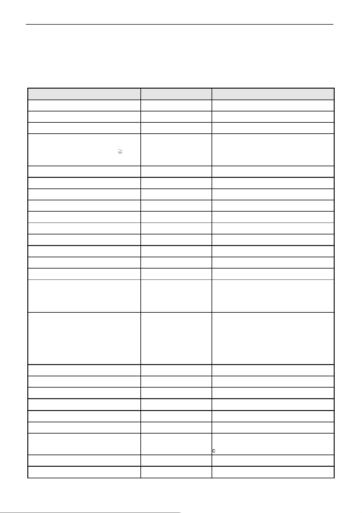
1 Monitor Specifications
1.1 Introduction
This specification describes ASUS PA246Q, a 24” Wide multi-interface (Analog +DVI +HDMI +DisplayPort) color
TFT LCD monitor. The display supports up to 1920*1200/60 Hz resolution & refresh rate and 1.07 billion colors
(HDMI & DP).The features summary is shown below,
Feature items Specifications Remark
Panel supplier & Panel type of supplier LGD LM240WU4-SLB3 Transmissive mode, normally black
Actual Size Diagonal display 24” Wide (16:10) Panel display size
Actual Resolution display (1920x1200/60Hz) Panel display resolution
178 degrees Horizontal
(at Contrast Ratio ≧ 10)
Color Gamut 102%
Analog interface with Scaling supported Yes With 15 pin D-sub connector
DVI interface with Scaling supported Yes With 24 pin DVI-D connector
(typ.)
178 degrees Vertical (typ.)
Panel spec
HDCP supported Yes
HDMI supported Yes With 19 pin HDMI connector
DisplayPort supported Yes With 20 pin DisplayPort connector
No N.A.
Max resolution mode supported 1920x1200@60Hz
Number of Display Colors supported 1.07 billion colors 8-bit + A-FRC,
Contrast Ratio 1000:1 (typ.)
The monitor would increase the backlight
Dynamic Contrast Ratio 50000:1
1.) LCD panel luminance
spec: 400 cd/m2 (typ.)
320 cd/m2 (min.)
Luminance
Yes 100-240Volts, 50/60 Hz.
DC power input (with AC power adapter) No
2.) Monitor’s factory
default luminance spec:
270 cd/m2 (typ.)
370 cd/m2 (max.)
when display a dark image.
Scenery Mode : under 7 gray scale
Theater Mode : under 17 gray scale
1.) Panel luminance spec is measured at
saturated R/G/B and CCFL=6~7mA (typ.)
condition.
2.) Monitor’s factory default luminance spec
is measured at User Mode default color
temperature (6500K).
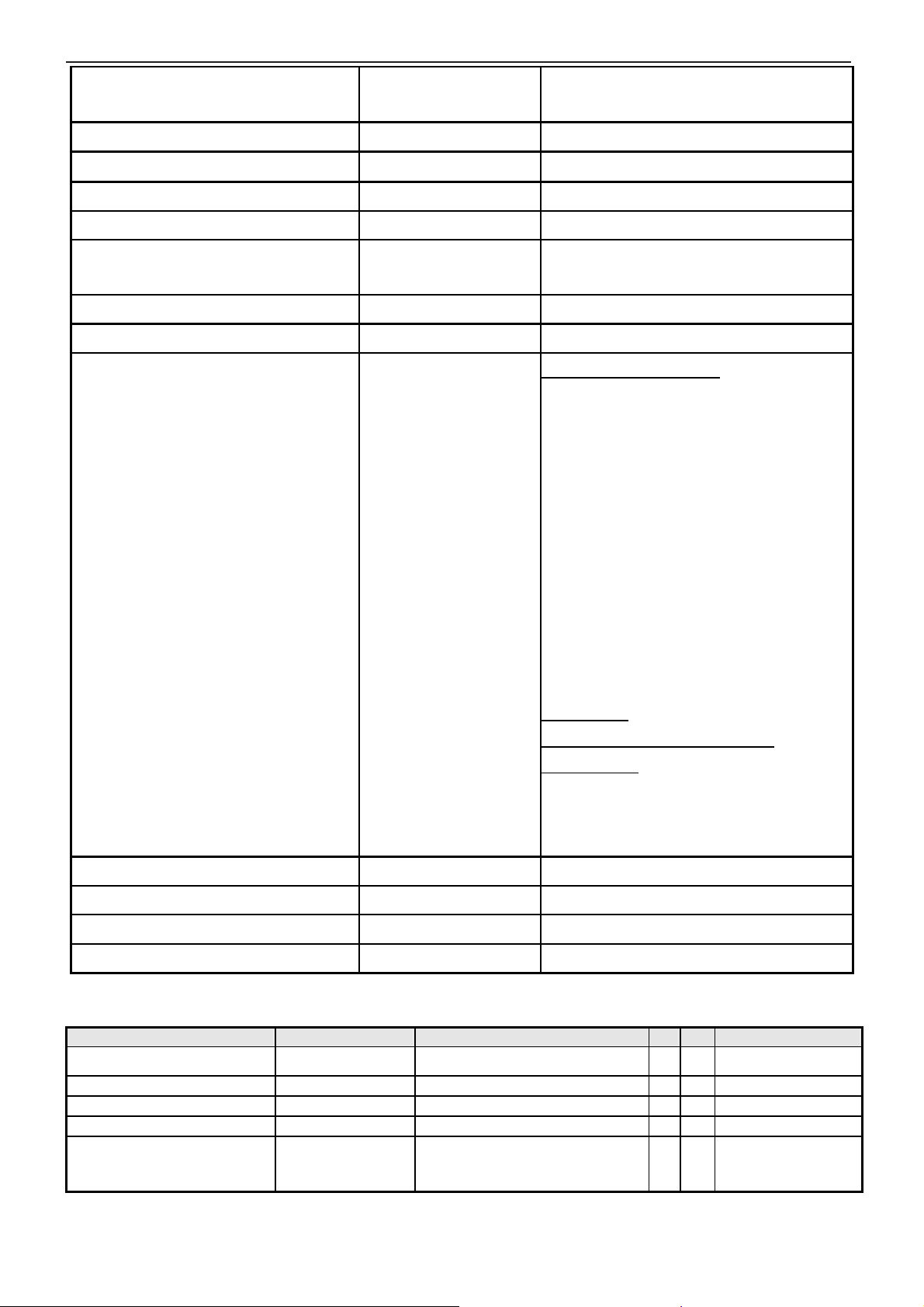
DPMS supported < 1 Watt
LED indicator for power status showed Yes White/Orange/Non
OSD for control & information supported Yes
Multi-language supported for OSD Yes 10 languages
Buttons control supported Yes
Flywheel control supported No
Scaling function supported Yes ST STDP8028(Mars)
control button
6
Page 4
Service Manual PA246Q
Earphone Jack (output connector)
SD / TransFlash Card /
VESA wall mounting design
Auto adjustment function supported Yes
DDC function supported (EDID ver.1.3) Yes DDC2B
DDC-CI support version 1.1 or later Yes DDC-CI
Audio speakers supported No
Audio Jack (input connector) supported No
Yes
supported
Microphone function supported No N.A.
USB 2.0 hub supported Yes 2 USB ports
Press and hold “Splendid-key” for 2 ~ 4
seconds
Supported Media Types :
Memory Stick (MS),
High Speed Memory Stick (HSMS),
Memory Stick PRO (MSPRO),
Memory Stick Duo(w Adapter),
MS Duo Secure Digital (Mini-SD),
Secure Digital Card,
Card reader supported Yes
Mechanical Tilt base design Yes
Yes
Mechanical Rotate design Yes
Mechanical Lift base design Yes
1.2 Dimension
Mini Secure Digital(w Adaptor),
TransFlash(SD, including SDHC),
MultiMediaCard(MMC),
Reduced Size MultiMediaCard(RS-MMC),
NAND Flash,
xD
Card Slots :
Lower Slot (built-in Push Ejection
Mechanism):
SD / MS / MMC/xD – direct insertion
MS Duo / Mini-
RS-MMC – with adapter
Item Condition Spec OK N.A Remark
Bezel opening
Monitor without Stand L x W x D mm 558.4*380.8*79 mm
Monitor with Stand L x W x D mm 558.4*380.8*235 mm
Carton Box (outside) L x W x H mm 683*457*298 mm
Tilt, Swivel and Lift range Tilt: -5/+20 degree
520.4 x 326 mm
Swivel: ±60 degree
Lift: 100mm
7
√
√
√
√
√
Page 5
Service Manual PA246Q
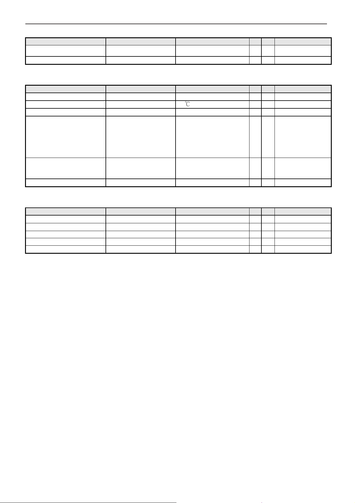
1.3 Weight
Item Condition Spec OK N.A Remark
Monitor (Net)
Monitor with packing (Gross) 10 kg + 5%
7.3 kg
+/- 4%
√
√
1.4 Plastic
Item Condition Spec OK N.A Remark
Flammability UL 94 HB
Heat deflection To ABS
UV stability ABS Delta E < 3.0
Resin
Texture MT-11000
Color DB39A
ABS/HB
75 ℃
GPPC D350
BASF GP-35
CHEIL SD0150
CHIMEI PA757
LG HF380
KINGFA HP-126
MT-11010
MT-11020
√
√
√
√
√
√
1.5 Carton
Item Condition Spec OK N.A Remark
Color
Material BC Flute
Compression strength 400 KGF
Burst Strength 18 KGF/cm2
Stacked quantity 7 layers
Color box
√
√
√
8
Page 6
Service Manual PA246Q
Any input resolution modes
are under
B saturated
03,
2 Operation Instructions
2.1 Video performance
Item Condition Spec OK N.A Remark
Resolution
Contrast ratio 1000:1(typ.)
Brightness
Response time
Viewing angle
CIE coordinate of White
Display colors 1.07 Billion colors
which
1920x1200
At R、G
condition
Rise Time
Decay Time
Gray to Gray
、
1920 x1200@60Hz
270 cd/m2 (typ.)
370 cd/m2 (max)
6 ms (typ.)
7 ms (typ.)
6 ms (typ.)
R/L 178(Typ.)
U/D 178(Typ.)
(0.313, 0.329) +/- (0.
0.03)
√
√
√
√
√
√
Only HDMI & DP
√
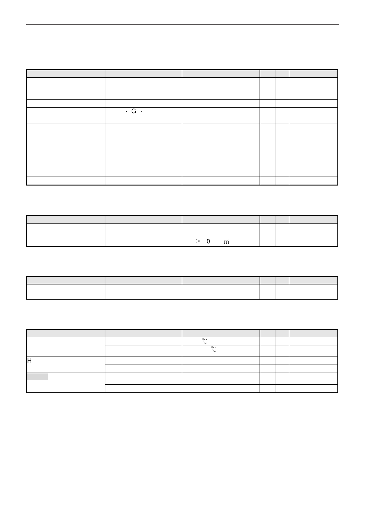
2.2 Brightness Adjustable Range
Item Condition Spec OK N.A Remark
Brightness adjustable range
At Max. Contrast level &
Full-white color pattern
(Max. brightness value –
Min. brightness value)
≧
100 cd/㎡
√
2.3 Acoustical Noise
Item Condition Spec OK N.A Remark
Acoustical Noise Front side distance : 30cm
Back side distance : 4cm
Front side < 23 dB
Back side < 28 dB
√
2.4 Environment
Item Condition Spec OK N.A Remark
Temperature Operating
Non-operating
Humidity Operating 10 ~ 90%
Non-operating 5 ~ 90%
Altitude Operating
Non-operating 0~12,192m (40,000ft)
0 ~ 40 ℃
-20 ~ +60 ℃
0~3,657m (12,000ft)
√
√
√
√
√
√
Non-condensing
Non-condensing
Without packing
With packing
9
Page 7
Service Manual PA246Q
2.5 Transportation
Item Condition Spec OK N.A Remark
Vibration Unpacked, Non-Operating 20 Hz, 0.0185 g2/Hz
200 Hz, 0.0185 g2/Hz
(Duration: 5 min Per AXIS)
Package Test
(1)Random Vibration
(2)Drop Package, Non-Operating 91 cm Height
Package, Non-Operating 1Hz, 0.0001 g2/Hz
4 ~100 Hz, 0.0001 g2/Hz
200 Hz, 0.001 g2/Hz
(Equivalent to 1.15 Grms)
(Duration: 30 min Per
surface on Z Axis)
(2 corners, 2 edges, 6
faces)
√
√
√
√
2.6 Electrostatic Discharge Requirements
Item Condition Spec OK N.A Remark
Electrostatic Discharge IEC801-2 standard Contact: 8KV
Air: 15KV
√
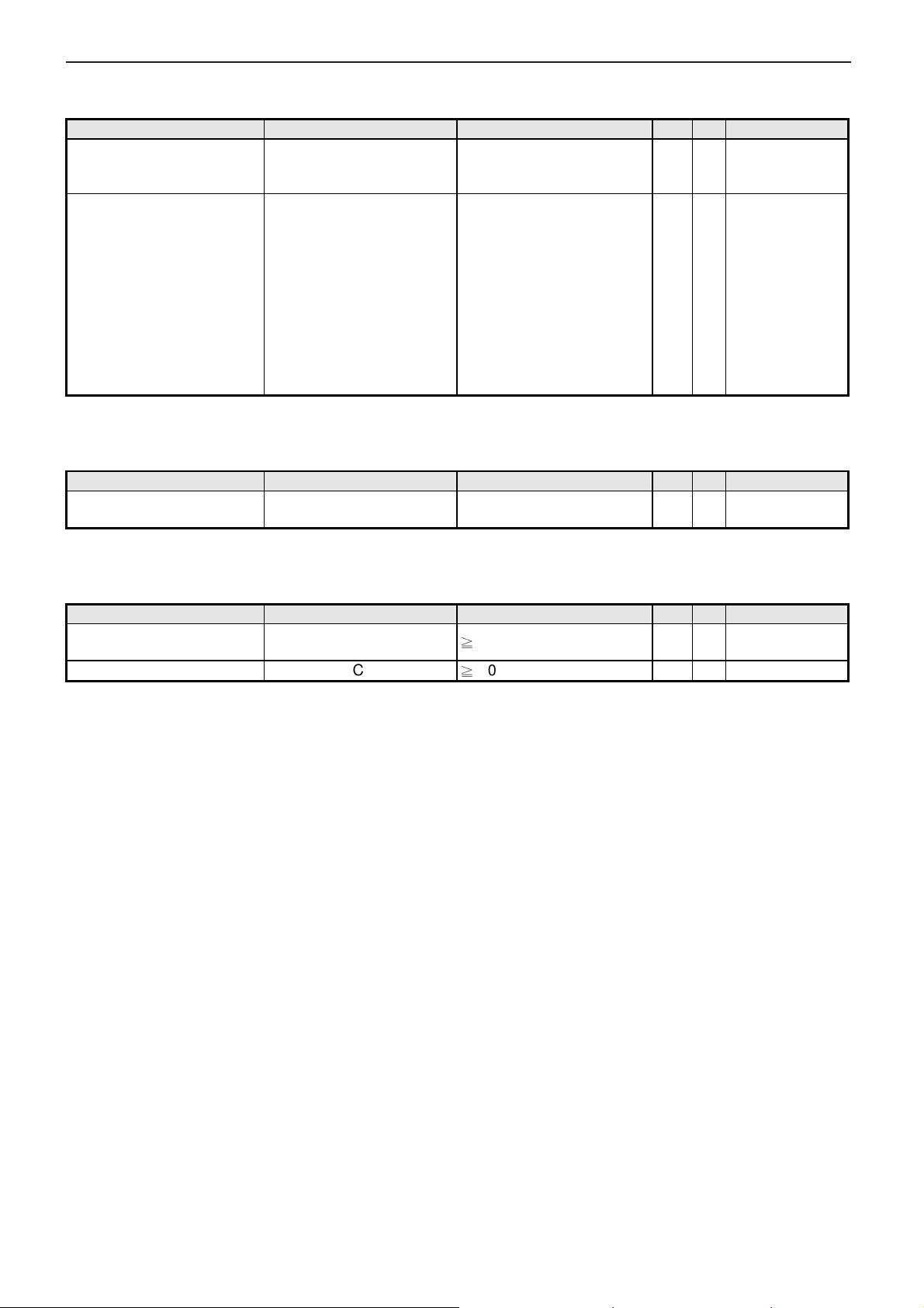
2.7 Reliability
Item Condition Spec OK N.A Remark
MTBF Prediction
CCFL Life time at 25 °C 2°C
Note: The lifetime of LED is defined as the time when LED packages continue to operate under the conditions at Ta
= 25 ±2 and I= (20)mA (per chip) until the brightness becomes _ 50% of its original value.
Refer to Telcordia
(Bellcore)
≧
80,000 Hours (goal)
≧
40,000 Hours (SA)
√
√
Excluding the
LCD, CCFL
See Note
10
Page 8
Service Manual PA246Q
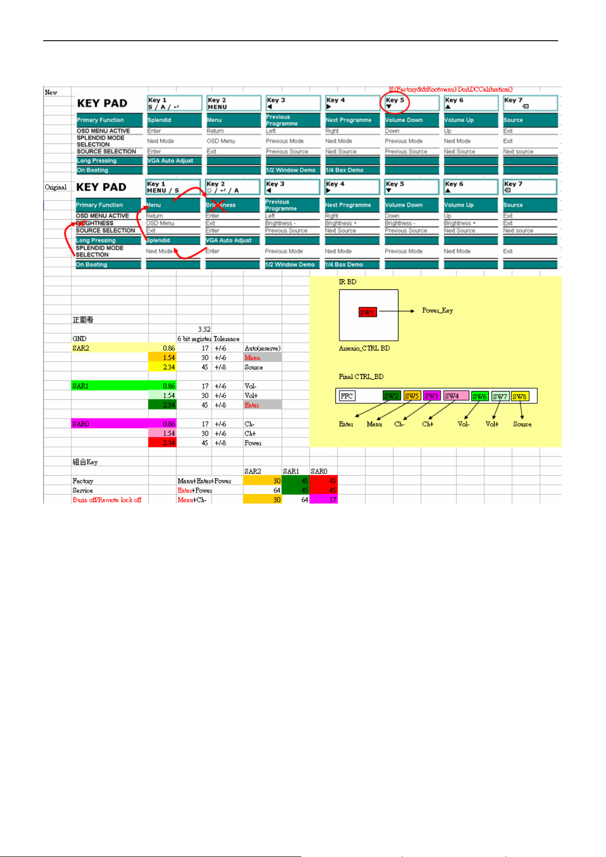
2.8 User’s hardware control definition:
11
Page 9
Service Manual PA246Q
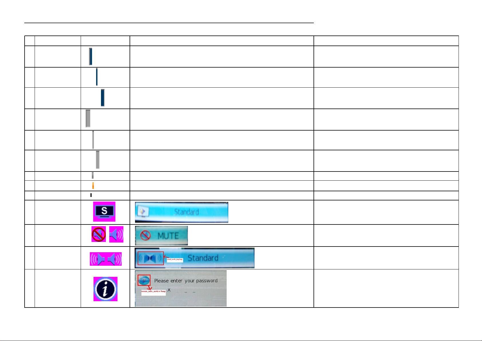
2.9 OSD control function definition
Item File Name Graphic Related OSD Comment
1 ButtonTypeC_F_L.png This will be used in those OSD for CI module. (Suggest : Do not change)
2 ButtonTypeC_F_M.png This will be used in those OSD for CI module(Suggest : Do not change)
3 ButtonTypeC_F_R.png This will be used in those OSD for CI module(Suggest : Do not change)
4 ButtonTypeC_N_L.png This will be used in those OSD for CI module(Suggest : Do not change)
5 ButtonTypeC_N_M.png This will be used in those OSD for CI module(Suggest : Do not change)
6 ButtonTypeC_N_R.png This will be used in those OSD for CI module(Suggest : Do not change)
7 grybar_cursor_b_m.png This will be used in those OSD for CI module(Suggest : Do not change)
8 grybar_cursor_f_m.png This will be used in those OSD for CI module(Suggest : Do not change)
9 grybar_cursor_n_m.png This will be used in those OSD for CI module(Suggest : Do not change)
10 shop_mode_img.bmp
volume_MUTE.bmp
11
volume_on.bmp
12 sound_mode_img.bmp
13 menu_info_notice.bmp
12
Page 10

Service Manual PA246Q
menu_info_notice.bmp
14
menu_button.bmp
menu_lock.bmp
menu_lock_hide.bmp
menu_time.bmp
menu_channel.bmp
15
menu_channel_hide.b
mp menu_option.bmp
menu_picture.bmp
menu_audio.bmp
volume_ball_blue.bmp
volume_ball_gray.bmp
volume_ball_purple.bm
16
volume_ball_purple_hid
p
e.bmp
13
Page 11
Service Manual PA246Q
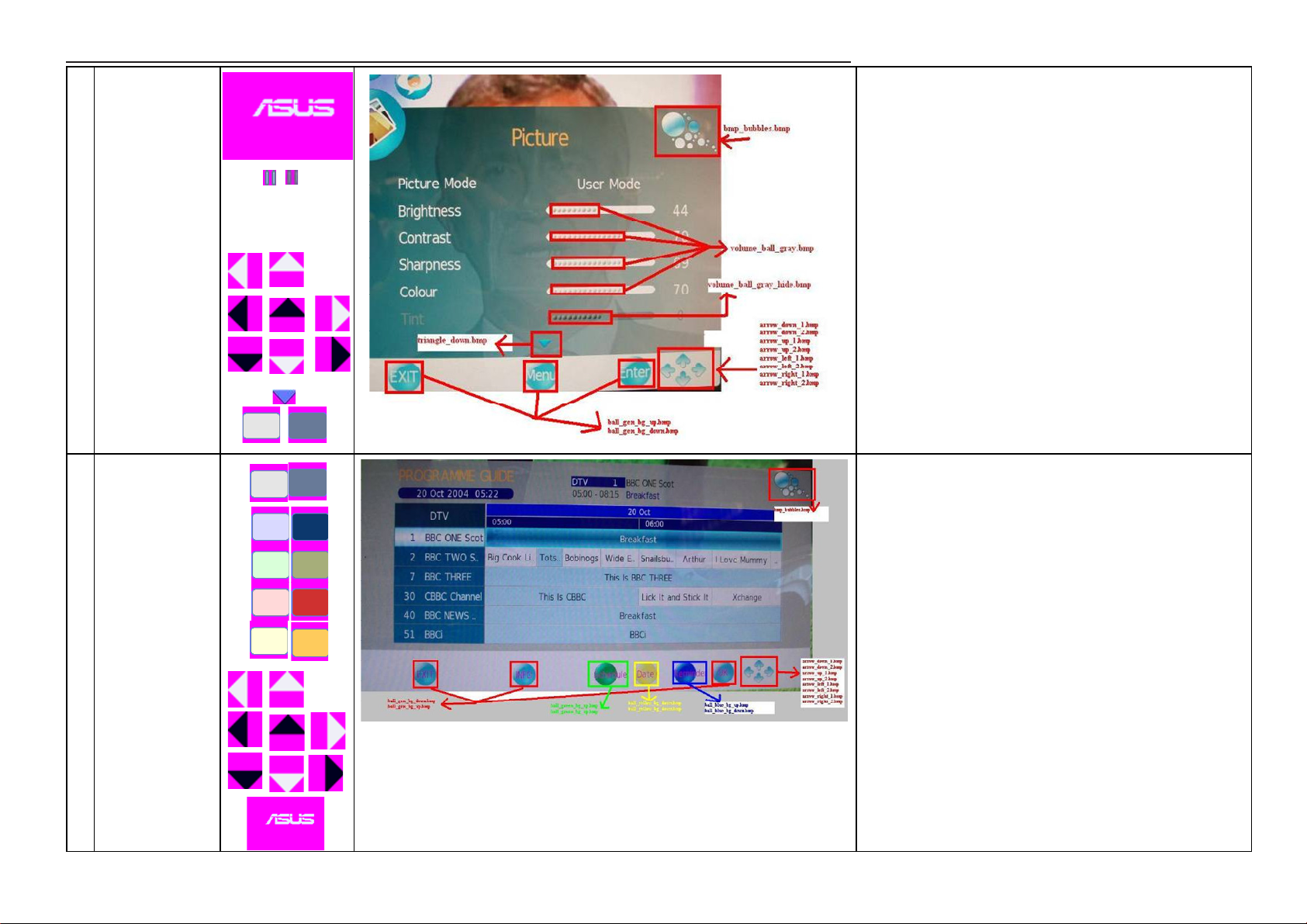
bmp_bubbles.bmp
volume_ball_gray.bmp
volume_ball_gray_hide.
17
bmp
triangle_down.bmp
arrow_down_1.bmp
arrow_down_2.bmp
arrow_up_1.bmp
arrow_up_2.bmp
arrow_left_1.bmp
arrow_left_2.bmp
arrow_right_1.bmp
arrow_right_2.bmp
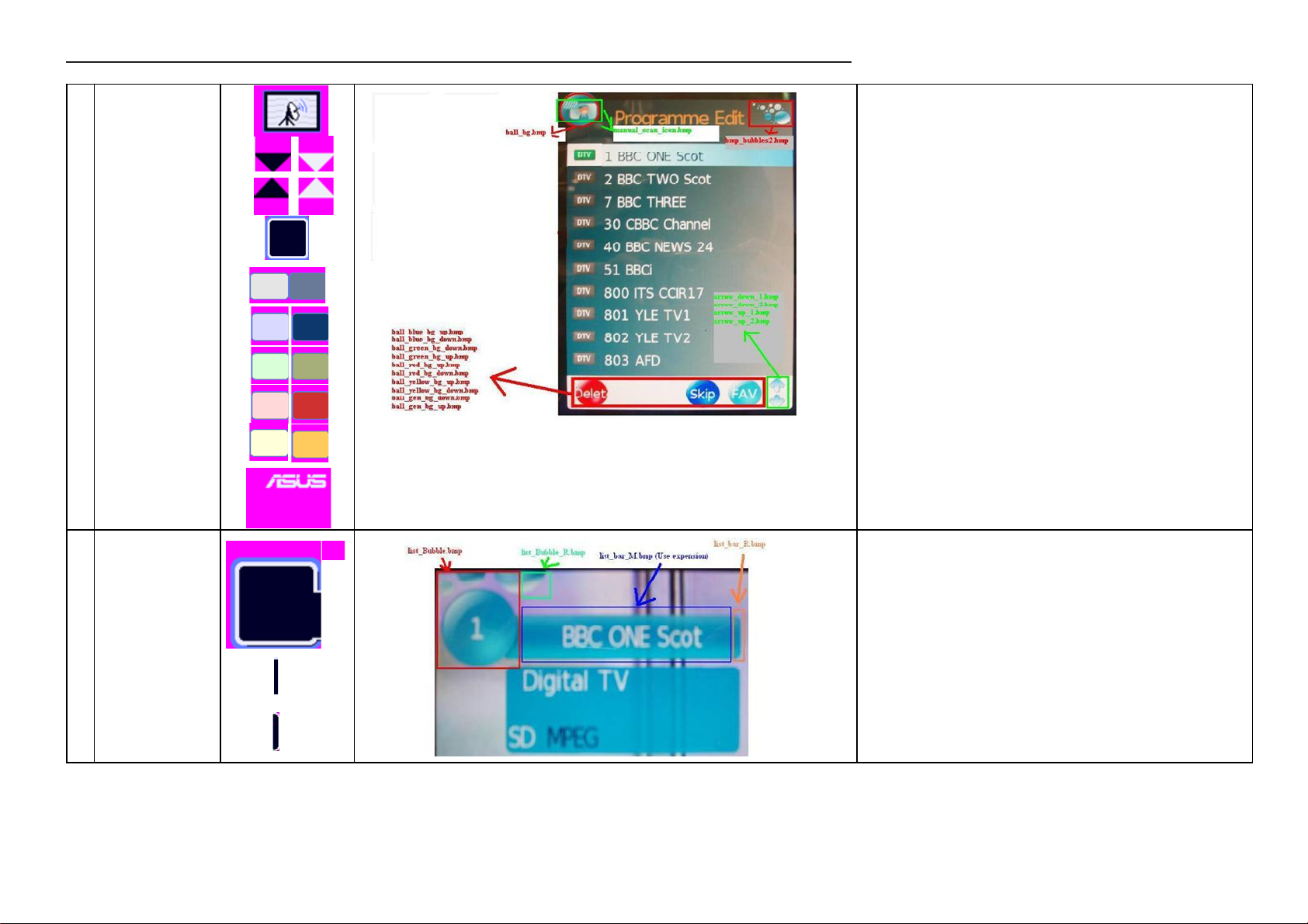
ball_yellow_down.bmp
ball_yellow_bg_up.bmp
ball_gen_bg_up.bmp
ball_gen_bg_down.bmp
ball_green_bg_up.bmp
ball_green_bg_down.b
18
ball_blue_bg_down.bm
p arrow_down_1.bmp
arrow_left_1.bmp arrow
mp
ball_blue_bg_up.bmp
arrow_down_2.bmp
arrow_up_1.bmp
arrow_up_2.bmp
14
Page 12
Service Manual PA246Q
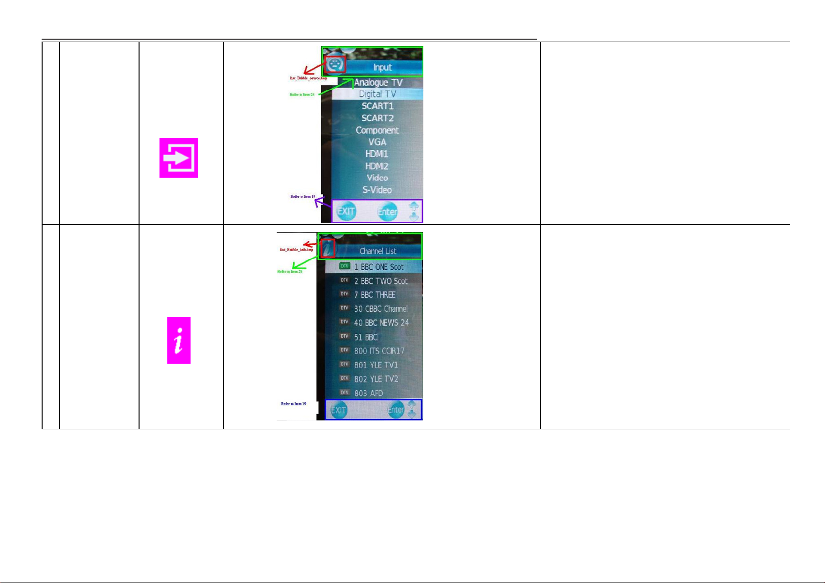
ball_bg.bmp
manual_scan_icon.bmp
bmp_bubbles2.bmp
ball_blue_bg_up.bmp
ball_blue_bg_down.bm
ball_green_bg_down.b
19
ball_green_bg_up.bmp
ball_red_bg_up.bmp
ball_red_bg_down.bmp
ball_yellow_bg_up.bmp
ball_yellow_bg_down.b
ball_gen_bg_down.bmp
p
mp
mp
ball_gen_bg_
Red (207, 49, 48)
Yellow (254, 203, 92)
Green (166, 174, 122)
Blue(213, 89, 43)
20
list_Bubble.bmp
list_Bubble_R.bmp
list_bar_M.bmp
list_bar_R.bmp
15
Page 13
Service Manual PA246Q
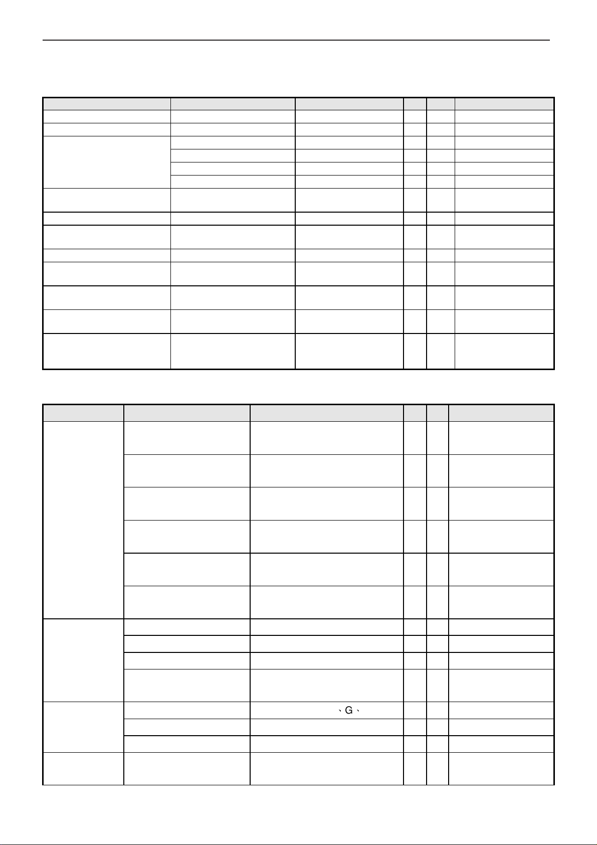
21 list_Bubble_source.bmp
22 list_Bubble_info.bmp
1. Please refer to Item24 for the title bar on the up. 2. Please refer to Item 19
for the bottom of the OSD
1. Please refer to Item24 for the title bar on the up. 2. Please refer to Item 19
for the bottom of the OSD
* The detailed firmware functions’ specification, please refer to C212 S/W spec. document.
16
Page 14
Service Manual PA246Q
pin DisplayPort
pin DisplayPort
3 Input/Output Specification
3.1 Power supply
Item Condition Spec OK N.A
Input Voltage range Universal input full range 100-240V, 50/60 Hz
Input Current range 100 ~ 240VAC < 2 Arms
Normal “On” operation < 130 Watts
Power Consumption
Inrush Current
Earth Leakage Current 264 VAC/50Hz < 3.5 mA
Hi-Pot
Power Line Transient IEC1000-4-4 1KV
IEC1000-4-5 (Surge)
CCFL operation range 90 ~ 264VAC
CCFL Frequency 90 ~ 264VAC
Power cord
DPMS “Sleep” state ≤ 1 W
DPMS “Off” state ≤ 1 W
AC Power Switch Off 0 W
110 VAC
220 VAC
1. 1500VAC, 3 sec
2. Ground test: 30A, 3sec
< 30 A (peak)
< 60 A (peak)
Without damage
< 0.1 ohm
Common: 2KV,
Differential: 1KV
6mA ~ 7mA
(With 100% Duty)
54KHz ~ 58KHz
(With 100% Duty)
Color: Black
Length: 1800mm +/50mm
3.2 Signal interface
√
√
LED: White
√
LED: Orange
√
LED: Off
√
LED: Off
√
Cold-start
√
√
√
√
√
Panel spec.
√
Panel spec.
√
√
Remark
(on-line test)
(in-lab test)
Item Condition Spec OK N.A Remark
Color: Black
Length: 1800 mm
Color: Black
Length: 1800 mm
Color: Black
Length: 1800 mm
Color: Black
Length: 2000 +/- 50mm
Color: Black
Length: 1800 +/- 30mm
Color: Black
Length: 1800 mm
See Note 4
Separate H/V-sync
(Positive/Negative)
√ with blue connector
√ with white connector
√
√ DP 1.1 protocol
√
√ with green Jack
√ For 20-
For 15 pin D-sub
√
Signal Cable
Pin assignment
Analog
Sync
D-Sub
DVI-D
HDMI
Displayport (DP)
USB 2.0 cable
Audio
15 pin D-sub connector See Note 1 √ For 15 pin D-sub
24-pin DVI-D connector See Note 2 √ For 24-pin DVI-D
19-pin HDMI connector See Note 3 √ For 19-pin HDMI
20-
connector
Signal type Separate analog R、G、B √ For 15 pin D-sub
Level 700 mV +/- 5% (peak to peak) √
Impedance 75 Ohms +/- 2% Ohms √
Signal type
17
Page 15
Service Manual PA246Q
DDC Clock
TMDS RX0+
Refer to VESA VSIS
Standard V1R1
Digital input
HDMI input
Level
Impedance Minimum 2.2KΩ(pull down) √ 2.2KΩ for application
Level
Impedance
Level 600mV for each differential line √
Impedance
Level 600mV for each differential line √
Logic High: 2.0V ~ 5.5V
Logic Low: 0V ~ 0.8V (TTL level)
600mV for each differential line
100 Ohm TDR Scan needed for
DVI cable and interface board
100 Ohm differential TDR Scan
needed for HDMI cable and
interface board
√
√
√
√
DisplayPort input
Impedance
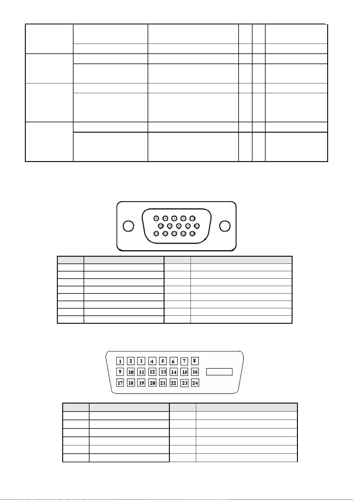
Note 1: The pin assignment of D-sub , DVI , HDMI , DisplayPort connectors are as below:
15 pins D-sub connector (Female):
Pin Signal Assignment Pin Signal Assignment
1 Red video 9 PC5V (+5 volt power)
2 Green video 10 Sync Ground
3 Blue video 11 Ground
4 Ground 12 SDA
5 Cable-Detect 13 H-Sync (or H+V)
6 Red Ground 14 V-sync
7 Green Ground 15 SCL
8 Blue Ground
Note 2: The pin assignment of 24-pin DVI-D connector (Female) is as below,
100 Ohm differential TDR Scan
needed for DisplayPort cable and
interface board
√
Pin Signal Assignment Pin Signal Assignment
TMDS RX2-
1
TMDS RX2+
2
TMDS Ground
3
TMDS RX4-
4
TMDS RX4+
5
6
18
TMDS RX3+
13
+5V Power
14
Self-test (Cable detect)
15
Hot Plug Detect
16
TMDS RX0-
17
18
Page 16
Service Manual PA246Q
DDC Data
TMDS Ground
Floating
TMDS RX5
-
TMD
S RX1
-
TMDS RX5+
TMDS RX1+
TMDS Ground
TMDS Ground
TMDS Clock+
TMDS RX3
-
TMDS Clock
-
7
8
9
10
11
12
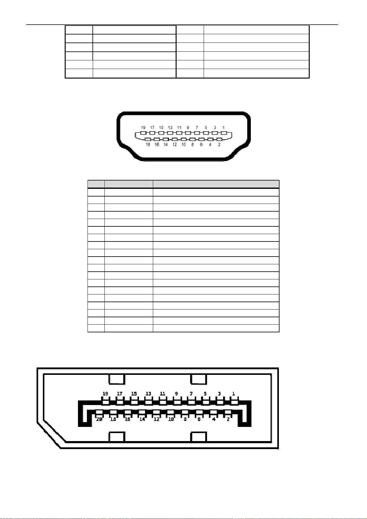
Note 3: Type A (Receptacle) HDMI
HDMI Digital connector pin assignments
PIN MNEMONIC SIGNAL
1 TX 2 + TMDS Data 2 +
2 SHLD 2 TMDS Data 2 Shield
3 TX 2 - TMDS Data 2 4 TX 1 + TMDS Data 1 +
5 SHLD 1 TMDS Data 1 Shield
6 TX 1 - TMDS Data 1 7 TX 0 + TMDS Data 0 +
8 SHLD 0 TMDS Data 0 Shield
9 TX 0 - TMDS Data 0 10 TX CLK + TMDS Clock +
11 TX CLK SHLD TMDS Clock Shield
12 TX CLK - TMDS Clock 13 CEC Consumer Electronic Control
14 NC No Connect
15 DDC Clk DDC Clock
16 DDC Data DDC Data
17 GND CED and DDC Ground
18 +5V +5V Power (from the media box)
19 HPD Hot Plug Detect
19
20
21
22
23
24
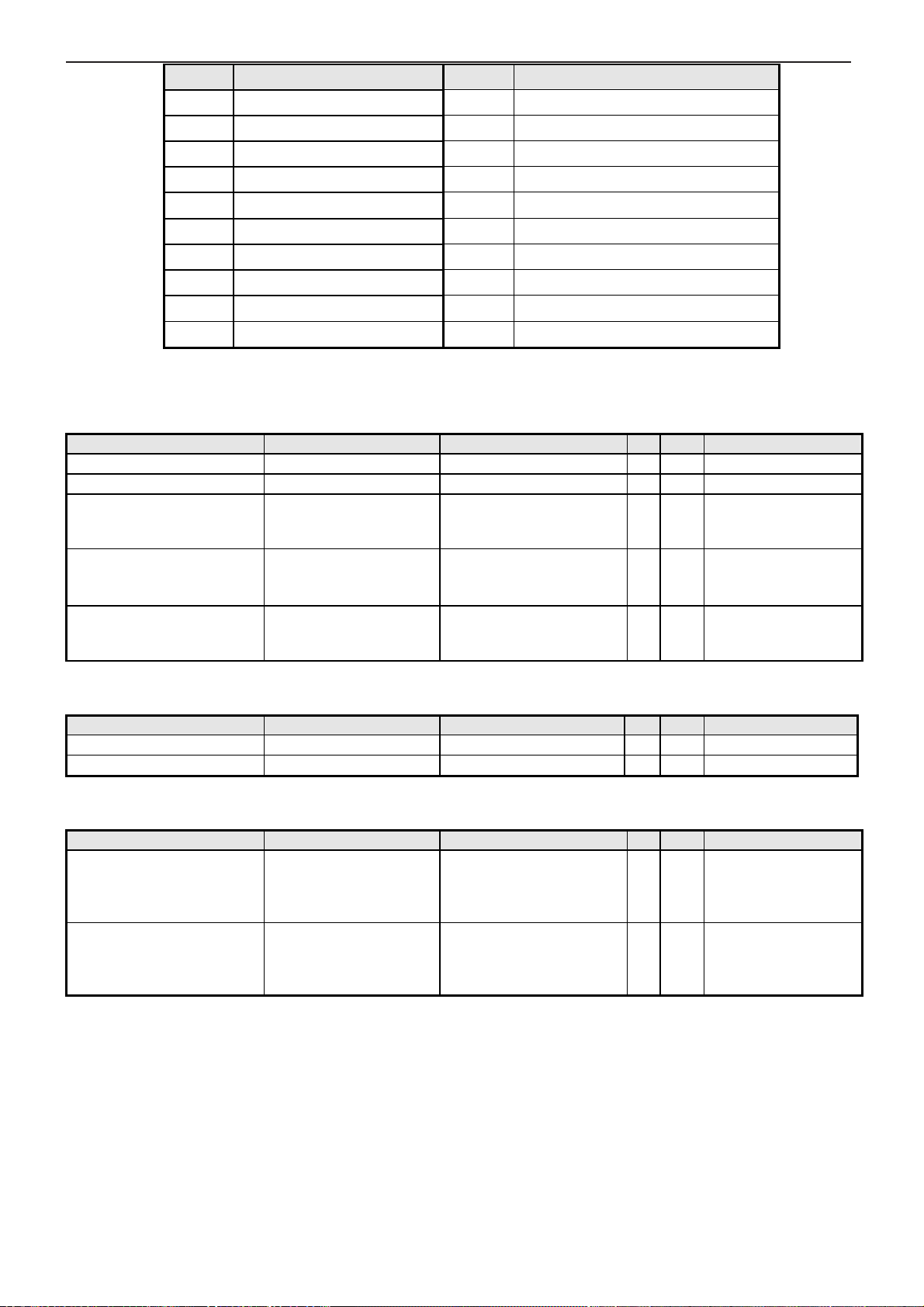
Note 4: The pin assignment of 20-pin DisplayPort connector is as below,
20-pins DisplayPort female
19
Page 17
Service Manual PA246Q
Ground
Lane3 N
Hot Plug Detect
Return
Lane3 P
DP_PWR
Refer to VESA VSIS
Refer to VESA VSIS
spec document to see
Pin Signal Assignment Pin Signal Assignment
Lane0 P
1
Ground
2
Lane0 N
3
Lane1 P
4
Ground
5
Lane1 N
6
Lane2 P
7
Ground
8
Lane2 N
9
10
11
12
13
14
15
16
17
18
19
20
Ground
EDID WP
AUX_CH P
Ground
AUX_CH N
3.3 Input Video Signal Performance Requirement
Item Condition Spec OK N.A Remark
Max. support Pixel rate 193.25 MHz
Max. Resolution 1920 x 1200@60Hz
Rise time + Fall time
(for D-sub input)
Settling Time after
overshoot /undershoot
Overshoot/Undershoot
< 2.509 ns
(50% of minimum pixel
clock period)
< 5% final full-scale value
< 12% of step function
voltage level over the full
voltage range
√
√
√
√
√
DVI only 165 MHz
1920x1200 @ 60Hz
(max. support timing)
Standard V1R1
Standard V1R1
3.4 Scan range
Item Condition Spec OK N.A Remark
Horizontal 31 ~ 83 KHz
Vertical 50 ~ 76 Hz
√
Without Frame buffer
√
3.5 Plug & Play DDC2B Support
Item Condition Spec OK N.A Remark
DDC channel type DDC2B / DDC-CI
EDID
Version 1.3
Refer to Q212 S/W
√
the detailed DDC-CI
command list.
Refer to Rebel Q212
√
S/W spec document
to see the detailed
EDID data definition.
20
Page 18

Service Manual PA246Q
3.6 Support Timings
VGA+DVI+HDMI (PC)
Input Timing
Resolution
640x480 31.47(N) 59.94(N) 25.18
640x480 35.00(N) 66.66(N) 30.24
640x480 37.87(N) 72.82(N) 31.5
640x480 37.5(N) 75.00(N) 31.5
720x400 31.47(N) 70.08(P) 28.32
800x600 35.16(P) 56.25(P) 36.00
800x600 37.88(P) 60.32(P) 40.00
800x600 48.08(P) 72.12(P) 50.00
800x600 46.86(P) 75.00(P) 49.50
832X624 49.72(P/N) 74.55(P/N) 57.28
1024x768 48.36(N) 60.00(N) 65.00
1024x768 56.476(N) 70.069(N) 75.00
1024x768 60.02(N) 75.00(N) 78.75
1152x864 67.5(P/N) 75.00(P/N) 108.00
1280x960 60.00(P) 60.00(N) 108.00
1280x1024
1280x1024
1366x768 47.712(P) 59.79(P) 85.50
1440x900 55.94(N) 59.89(P) 106.50
1600x1200
1680x1050
1920x1080
1920x1200
(Reduced
Blanking)
1920x1200
Horizontal
Frequency
(KHz)
63.98(P) 60.02(P) 108.00
79.98(P) 75.02(P) 135.00
75.00(P) 60.00(P) 162.00
65.29(N) 60.00(P) 146.25
67.5(P) 60.00(P) 148.5
74.038(P) 59.95(N) 154 1920x1200
74.556(N) 59.885(P) 193.25
Vertical
Frequency (Hz)
Dot Clock
Frequency
(MHz)
Actual display
Resolution
1920x1200
1920x1200
1920x1200
1920x1200
1920x1200
1920x1200
1920x1200
1920x1200
1920x1200
1920x1200
1920x1200
1920x1200
1920x1200
1920x1200
1920x1200
1920x1200
1920x1200
1920x1200
1920x1200
1920x1200
1920x1200
1920x1200
1920x1200
OK N.A Remark
√
√
√
√
√
√
√
√
√
√
√
√
√
√
√
√
√
√
√
√
√
√
√
√
VESA
VGA
Macintosh
VESA
VGA
VGA
SVGA
VESA
SVGA
VESA
APPLE
VESA
UVGA
VESA
VESA
VESA
VESA
VESA
VESA
CVT
1.30MA
VESA
CVT
1.76MA
VESA
VESA
Note: “P”, “N” stands for “Positive”, “Negative” polarity of incoming H-sync/V-sync (input timing)
Timing mode:
When the monitor is operating in the video mode (ie, not displaying data) using the HDMI connector, the following
high definition modes shall be supported in addition to standard definition video.
Timing Name
Preset
1
2
3
4
5
6
480p
720p60
576p
720p50
1080p60
1080p50
Pixel
Format
720x480 31.469 60 27
1280x720
720X576
1280X720
1920x1080
1920x1080
Horz Freq
(kHz)
45 60 74.25
31.25 50 27
37.5 50 74.25
67.5 60 148.5
56.25 50 148.5
21
Vert Freq
(kHz)
Pixel Rate
(MHz) OSD Display
480p-60Hz
720p-60Hz
576p-50Hz
720p-50Hz
1080p-60Hz
1080p-50Hz
Page 19

Service Manual PA246Q
EEPROM
IInntteerrffaaccee bbooaarrdd
Reader
USB
CCoonnttrrooll bbooaarrdd
Ctrl BD
EEPROM
EEPROM
EEPROM
USB
Power
Power
PPoowweerr bbooaarrdd
Backligh
Ctrl BD
bbooaarrdd
4 Block Diagram
4.1 Function block
PA246Q is a 24” WUXGA (1920x1200) resolution TFT LCD monitor. The monitor shall support VGA,
DVI, Displayport and HDMI with HDCP inputs. Moreover, PA246Q equips headphone out to enhance its
features and one USB upstream, two USB inputs and card reader. It’s compliant with VESA specification to
offer a smart power management and power saving function. It also offers OSD menu for users to control
the adjustable items and get some information about this monitor, and hotkey function is to offer users an
easy method to set some common functions by pressing several hotkeys which also include some auto
adjust functions.PA246Q also offer DDC/CI function to meet VESA standard.
A246Q consists of a head and a stand (base). The head consists of a LCD module with lamps, a
power board, a control board, a USB hub board and an interface BD.
The block diagram is shown as below.
Inverter
DC to DC
AC to DC
AC Input
AC Power
DDR2
DDR2
Display
Port
LCD panel module
LVDS Conn. 1 LVDS Conn. 2
STDP8028-AB
Scaler
HDMI
DVI
D-sub
Firmware
16M bits
Earphone
Out
Flash
24C32
USB
up stream
UUSSBB HHuubb
7 keypads + LED
(blue, amber)
Card
USB 1
USB 2
A. Interface Board
A basic operation theory for this interface board is to convert analog signals of Red, Green and Blue
to digital signals of Red, Green and Blue, and to provide DVI port equipped with HDCP key, for receiving
DVI signal to generate high quality image. In addition, it provides HDMI and Displayport input ports,
equipped with HDCP key, for receiving HDMI and Displayport signals to generate high quality image
and audio. The scaling IC has internal A/D converter, internal OSD and auto detect input timing
22
Page 20

Service Manual PA246Q
functions. A/D converter converts analog signal to digital data. OSD is offering adjustable functions to
end-user. Detect timing is for detect change mode. Scalar generates the pixel clock to the T-CON.
Finally output the digital RGB data, the Hsync, Vsync and pixel clock to LCD panel driver IC.MCU offers
H/W DDC2BI function & controls system processing. EEPROM is stored DDC data, OSD common data
and user mode data. A headphone audio circuit is also provided by interface board to add the
headphone output features.
(a) IC introduction
1. ST STDP8028 is an all-in-one LCD monitor controller supporting WUXGA, and integrates ST high
performance ADC, TMDS Rx with HDCP, scaling engine, OSD engine, LVDS Tx, and so on.
2. EEPROM: We use 24C32 to store all the adjustable data and user settings. The HDCP KEY is stored in
it.
3. Serial Flash: It controls all the functions of this interface board, just like the OSD display setting, the
adjustable items, adjusted data storage, the external IIC communication, support DDC2BI.
4. SMSC USB2649 IC: The 2-port USB HUB is fully compliant with USB 2.0 specification and will attach to
an upstream port as a Full-/High- Speed HUB.
B. Power Board Diagram
Fig.1
#1 EMI Filter
This circuit is designed to inhibit electrical and magnetic interference for meeting FCC, VDE, VCCI
standard requirements.
23
Page 21

Service Manual PA246Q
A logic signal (active low) disables the device (sleep mode operation).
A capacitor connected between this pin and ground determines the
soft start time. When this pin is grounded disables the device (driven
An external resistor connected between the unregulated input voltage
and this pin and a capacitor connected from this pin to ground fix the
A capacitor connected between this pin and OUT allows to drive the
in an
output voltage of 3.3V. An external resistive divider is required for
#2 Converter Circuit – L4978
The L4978 is a step down monolithic power switching regulator delivering 2A at a voltage between
3.3V and 50V (selected by a simple external divider). Realized in BCD mixed technology, the device
uses an internal power D-MOS transistor (with a typical R
of 0.25Ω) to obtain very high efficiency
DS(on)
and high switching speed.
A switching frequency up to 300 kHz is achievable (the maximum power dissipation of the
packages must be observed). A wide input voltage range between 8V to 55V and output voltages
regulated from 3.3V to 50V cover the majority of today’s applications.
Features of this new generation of DC/DC converter include pulse-by-pulse current limit, hiccup mode
for short circuit protection, voltage feed-forward regulation, soft-start, protection against feedback loop
disconnection, inhibit for zero current consumption and thermal shutdown.
Pin Assignment of L4978
Pin No. Names Function
1 GND Ground
2 SS_INH
by open collector/drain).
3 OSC
switching frequency. (Line feed forward is automatically obtained)
4 OUT Step-down regulator output
5 VCC Unregulated DC input voltage
6 BOOT
internal DMOS Transistors
7 COMP E/A output to be used for frequency compensation
Step-down feedback input. Connecting directly to this pin results
8 FB
higher output voltages.
24
Page 22

Service Manual PA246Q
5 Schematic Diagram
5.1 Power Board
25
Page 23

Service Manual PA246Q
5.2 Control Board
26
Page 24

Service Manual PA246Q
5.3 Interface Board
27
Page 25

Service Manual PA246Q
28
Page 26

Service Manual PA246Q
29
Page 27

Service Manual PA246Q
30
Page 28

Service Manual PA246Q
31
Page 29

Service Manual PA246Q
6 PCB layout
6.1 Power Board
32
Page 30

Service Manual PA246Q
6.2 Control Board
6.3 Interface Board
33
Page 31

Service Manual PA246Q
10 Color/White balance Adjustment
Alignment procedure (for function adjustment)
A list of necessary alignments for the LCD monitor:
Items
1 Timing adjustment Preset timing
2 Auto color balance adjustment Timing 114
3 Color temperature adjustment Cool (9300K),
4 Writing EDID file Analog, Digital, HDMI,
Preparation:
1. Setup input timing to any preset modes or patterns.
2. Enter factory mode (Press menu key and up key then press power key, hold on about 2 sec will enter
the factory mode.).
3. Move cursor into “BURN IN” tag then press menu key to select “ON” enable burn-in mode.
4. Power off the monitor, remove the input source and then power on again.
5. Setup unit and keep it warm up for at least 30 minutes.
Timing adjustment: (Analog only, it is not required for DVI-D
Description Remark
VGA 480 640x480@60Hz
or Timing 118
800x600@60Hz
Pattern 42(5-Mosaic)
Normal (6500K),
Warm (5000K)
Displayport
、、、、
HDMI
、、、、
DP input source)
1. Enter factory mode (Press menu key and up key then press power key, hold on about 2 sec will enter the
factory mode.).
2. Select timing mode from table 1 and input full screen display pattern to monitor.
3. Press “Splendid button -Key” and hold for 2 seconds to run “AUTO adjustment” function for geometry
adjustment.
4. Clear user area in EEPROM.
5. Check if the position, phase and clock of the image are ok or acceptable to make sure function and
performance are ok.
6. Turn off the monitor power.
7. Turn on the monitor power again to check if monitor’s image settings are ok and with following settings.
CONTRAST = 80
BRIGHTNESS = 50
COLOR = 6500K (default setting)
Auto color balance adjustment: (Analog only, it is not required for DVI-D
1. Setup input timing VGA480 (640x480@60Hz) or Timing 118 (800x600@60Hz),pattern 42(5-Mosaic
pattern with white color frame) with Analog signals from Chroma video pattern generator.
2. Enter factory mode (Press menu key and up key then press power key, hold on about 2 sec will enter the
factory mode.).
3. Move black cursor into “BURN IN MODE” tag and select “ON” to enable burn-in mode.
4. Move black cursor into “Auto Color” tag and.Press “ Menu Key ” to do white balance for auto color balance
adjustment (will get optimal gain / offset values).
Color adjustment: (Analog only)
50
、、、、
HDMI
、、、、
DP input source)
Page 32

Service Manual PA246Q
1. Setup input timing to any preset modes, pattern 41(full white color pattern) with Analog signals from
Chroma video pattern generator.
2. Enter factory mode (Press menu key and up key then press power key, hold on about 2 sec will enter the
factory mode.).
3. Confirm auto color balance adjustment had already been done.
4. Measure each color temperature (C1, C2 & C3) by Minolta CA-110 (or equivalent equipment).
5. Two methods can be used to adjust RED, GREEN, BLUE value of each color temperature, C1, C2 & C3 to
meet following spec requirement, the 1
automatic adjustment, and the 2nd method is by manually and must be in factory mode.
st
method is by using external PC and IIC alignment protocol to do
Color temperature
(9300K set on OSD)
Color temperature
(6500K set on OSD)
Color temperature
(5000K set on OSD)
6. Turns off the monitor power.
Writing EDID file: (Analog, DVI-D, HDMI, and DP)
1. Setup a PC with DDC card.
2. Connect PC to monitor with a D-sub signal cable.
3. Provided the AC power to monitor.
4. Please refer to the C212 for the correct EDID file.
5. Runs the writing program to write the EDID file into EEPROM for Analog input.
6. Read EEPROM data and confirm if it’s matched with the definition.
7. Write digital EDID data into EEPROM for DVI-D/HDMI and DP input.
8. If adopting non EDID copy method then repeat Step 2-5 with designated digital video input and cable.
9. If adopting EDID copy method, please refer to attached file.
10. Read both EEPROM data and confirm if it’s matched with the C212 definition.
x+- 0.283+(-) 0.015
y+- 0.297+(-) 0.015
Y 200
x+- 0.313+(-) 0.015
y+- 0.329+(-) 0.015
Y 270
x+- 0.346+(-) 0.015
y+- 0.359+(-) 0.015
Y 230
51
Page 33

Service Manual PA246Q
11 Trouble Shooting
11.1 No Display or display is unstable (Interface Board):
Screen is Blank and
Power LED is white.
OSD shown when key pressed?
No
Keypad OK?
Yes
Backlight turned
ON?
Yes
Scalar output
Data ?
Yes
Yes
No
No
No
Follow instructions from OSD dialog
Proceed to
“Check Control Board”.
Proceed to
“Check Power Board”.
Proceed to
“Check Scalar”
“Check LCD Module”
52
Page 34

Service Manual PA246Q
11.2 Check Control Board
Checking Control
Board
Is control BD connecting?
No
Plug control board
then retry
control board PCB
OK?
Yes
Yes
No
Replace a new
control board, then
retry
Is botton key normally?
No
Yes
Replace the
components, then
retry
Check interface board Scalar
GPIO function
(TP48,TP49,TP50) ,then
proceed to check Scalar
53
Page 35

Service Manual PA246Q
11.3 Check Scalar:
54
Page 36

Service Manual PA246Q
11.4 Check LCD Module:
55
Page 37

Service Manual PA246Q
11.5 USB Hub (Upstream/Downstream Port) / Card reader does not work:
1. Check LDO regulator voltage to 5V is correctly
received and correctly convert to 3.3V & 1.2V
2. Further more, for the abnormal USB port, power
line of this USB port is advised to check.
1. If Vcc are OK, check crystal Y1 oscillates.
2. Reset circuit for USB Hub and Card Reader IC
are advised to check.
56
Page 38

Service Manual PA246Q
11.6 Check Inverter BD:
Check Inverter
Yes
Check CN801 Pin 6 (BL_ON)
Voltage ≈ 3.3V (High)
Yes
Check CN801 Pin 7
(BL_ADJ) Voltage ≈ 3.3V (High)
or PWM Signal
Yes
Check CN801 Pin 1~5
Voltage ≈ 24V
Yes
Replace Inverter BD
No
Check Power BD & I/F BD
No
Check Power BD & I/F BD
No
Check Power BD
57
Page 39

Service Manual PA246Q
11.7 Check Power BD:
Check Power BD
Yes
Check CN801 Pin 1~5
Voltage ≈ 24V
Yes
Check V-IF +5V
Voltage ≈ 5V
Yes
Check V-Panel +12V
Voltage ≈ 12V
No
No
Check F701 & F702
Yes
Check Q701 & Q702 & IC701
Yes
Check Q852 & D853 & IC851
Yes
Check Q851 & D851
& D852 & IC701
No
Replace F701 & F702
No
Replace Q701 & Q702 & IC701
No
Replace Q852 & D853 & IC851
No
Replace Q851 & D851& D852 & IC701
Yes
Check V-USB +5V
Voltage ≈ 5V
Yes
Replace Power BD &
Check Inverter BD & I/F BD
Yes
Check D881 & D882 & IC881
Yes
No
Replace D881 & D882 & IC881
58
Page 40

Service Manual PA246Q
11.8 Check PFC Function:
59
Page 41

Service Manual PA246Q
12 Exploded View
60
Page 42

Service Manual PA246Q
61
Page 43

Service Manual PA246Q
13 Recommended Parts List
RECOMMENDED SPARE PARTS LIST (RSPL)
Asus Model : PA246
Vendor Model: 9J.18R72.QL1/9J.18R72.QL2/9J.18R72.QL3/9J.18R72.QL5/9J.18R72.QLJ
Type Subset Vendor P/N Vendor Description Usage MOQ
DISPLAY PANEL(LGD) 5F.LLDUP.011 LCDM24W LM240WU4-SLB3 LGD P 1 1
ELECTRICAL MAIN BOARD(LGD) 5E.18R01.001 PCBA IF BD MI PA246 1 10
ELECTRICAL POWER BOARD 5E.18R02.001 PCBA SPS BD MI PA246 1 10
ELECTRICAL KEY BOARD 5E.18R03.001 PCBA CTRL BD MI PA246 1 10
ELECTRICAL USB BOARD 5E.18R08.001 PCBA USB BD MI PA246 1 10
MECHANICAL BEZEL ASSY 6K.18R11.001 ASSY BZL PA246 1 10
MECHANICAL BACK COVER 3J.18R02.011 RC ABS DB39A PA246 1 10
MECHANICAL STAND ASSY 6E.18R01.001 ASSY STAND HAB FULFIL PA246 1 10
TRIVIAL LVDS Cable 5K.18R04.001 WIRE LVDS 51/20/30P #28 PA246 1 50
TRIVIAL KEY BOARD wire 5K.18R03.001 WIRE FFC 8P CTRL BD PA246 1 50
TRIVIAL POWER BOARD wire_to Panel 5K.18R01.001 WIRE 14/12P 1061 #24 PWR PA246 1 50
TRIVIAL POWER BOARD wire 5K.18R02.001 WIRE 12/13P 1571 #24 PWR PA246 1 50
TRIVIAL USB BOARD wire 5K.18R05.001 WIRE 7/11P #28 PA246 1 50
TRIVIAL Tape 3H.04054.071 TAPE ADHESIVE 35*25 BLK 7651F 1 100
TRIVIAL Label_SPEC 4E.0VU01.041 LBL SPEC 88*28 PA246 WW 1 100
TRIVIAL Label_Prevent 4E.L4603.051 LBL PREVENT 30*15 ASUS VH226H 1 100
TRIVIAL Label 4E.0KM04.001 LBL BLANK 43*14 WHITE 1 100
TRIVIAL Screw 8F.00551.3R0 SCRW M FPH M2*3L (6/1.4) NI 2 200
TRIVIAL Screw 8F.205B4.019 #SCRW MACH STEEL HEX #4-40 NI 4 200
TRIVIAL Screw 8F.5A224.6R0 #SCRW MACH FLAT M3*0.5P*6L ZN 2 200
TRIVIAL Screw 8F.HA334.8R0 SCRW TAP-S FPH M3*8(5/1.2) BZN 2 200
TRIVIAL Screw 8F.VG434.6R0 #SCRW TAP PH W/F M3*6TP-S ZN 11 200
TRIVIAL Screw 8F.VZ524.6R0 SCRW TAP FLAT+EXT M3*6L C-ZN 1 200
ACCESSORY Power Cord_EU 2G.00921.001 CORD H05VV-F 10A250V EUR 1.8M 1 50
ACCESSORY Power Cord_US 2G.01111.011 CORD SVT125V WO/SH1.8M US 1 50
62
Page 44

Service Manual PA246Q
ACCESSORY Power Cord_AUS 2G.01343.001 CORD 3ASL/75DU-IN 250V1.8M AUS 1 50
ACCESSORY Power Cord_UK 2G.03149.021 CORD H05VV-F 13A 1.8M UK 1 50
ACCESSORY Power Cord_CNS TW 2G.04811.001 CORD VCTF 7A125V 1.8M CNS-TW 1 50
ACCESSORY Power Cord_JAN 2G.03515.021 CORD VCTF7A125V 1.8M JAN DELL 1 50
ACCESSORY Warranty Card_EU 4J.17Y03.001 WARRANTY ASUS EU NONZBD LCD 1 20
ACCESSORY Warranty Card_AP 4J.17Y02.001 WARRANTY ASUS AP NON ZBD LCDED 1 20
ACCESSORY Warranty Card_TW 4J.17Y05.001 WARRANTY ASUS TW NONZBD LCDLED 1 20
ACCESSORY Warranty Card_NA 4J.17Y04.001 WARRANTY ASUS NA NONZBD LCD 1 20
ACCESSORY User's Guide 4J.18R01.001 GUIDE QS 31L ASUS PA246 1 20
ACCESSORY DVI Cable 5K.05407.511 CABLE DVI-D/DVI-D 1.8M IS_8 1 50
ACCESSORY USB Cable 5K.L1E04.501 CABLE USB 2.0A/B 1.8M OD3.8 1 50
ACCESSORY D-SUB Cable 5K.L2H06.511 CABLE SIGNAL/C H+V OD_5.5 1.8M 1 50
ACCESSORY DP Cable 5K.0GY11.501 CABLE DP/DP 20P 2M W/O CORE 1 50
ACCESSORY PE bag 4B.18R04.011 BAG EPE+HDPE 600*700 1 100
PACKING Carton 4D.18R01.001 CTN BC 683*457*298 COLOR PA246 1 100
PACKING Cushion_Front 4G.18R02.001 CUSHON FRONT PA246 1 100
PACKING Cushion_Back 4G.18R03.001 CUSHION BACK PA246 1 100
63
Page 45

Service Manual PA246Q
Photos of Recommended Parts List
1 2 3
4 5 6
7 8 9
10 11 12
13 14 15
64
Page 46

Service Manual PA246Q
Asus Model :
14 Different Parts List
RECOMMENDED SPARE PARTS LIST (RSPL)
PA246
Vendor
Model:
Type Subset Vendor P/N Vendor Description Usage MOQ 9J.18R72.QL1 9J.18R72.QL2 9J.18R72.QL3 9J.18R72.QL5 9J.18R72.QLJ
DISPLAY PANEL(LGD) 5F.LLDUP.011 LCDM24W LM240WU4-SLB3 LGD P 1 1 v v v v V
ELECTRICAL MAIN BOARD(LGD) 5E.18R01.001 PCBA IF BD MI PA246 1 10
ELECTRICAL POWER BOARD 5E.18R02.001 PCBA SPS BD MI PA246 1 10
ELECTRICAL KEY BOARD 5E.18R03.001 PCBA CTRL BD MI PA246 1 10
ELECTRICAL USB BOARD 5E.18R08.001 PCBA USB BD MI PA246 1 10
MECHANICAL BEZEL ASSY 6K.18R11.001 ASSY BZL PA246 1 10
MECHANICAL BACK COVER 3J.18R02.011 RC ABS DB39A PA246 1 10
MECHANICAL STAND ASSY 6E.18R01.001 ASSY STAND HAB FULFIL PA246 1 10
TRIVIAL LVDS Cable 5K.18R04.001 WIRE LVDS 51/20/30P #28 PA246 1 50
TRIVIAL KEY BOARD wire 5K.18R03.001 WIRE FFC 8P CTRL BD PA246 1 50
TRIVIAL
TRIVIAL POWER BOARD wire 5K.18R02.001 WIRE 12/13P 1571 #24 PWR PA246 1 50
TRIVIAL USB BOARD wire 5K.18R05.001 WIRE 7/11P #28 PA246 1 50
TRIVIAL Tape 3H.04054.071 TAPE ADHESIVE 35*25 BLK 7651F 1 100
TRIVIAL Label_SPEC 4E.0VU01.041 LBL SPEC 88*28 PA246 WW 1 100
TRIVIAL Label_Prevent 4E.L4603.051
TRIVIAL Label 4E.0KM04.001 LBL BLANK 43*14 WHITE 1 100
TRIVIAL Screw 8F.00551.3R0 SCRW M FPH M2*3L (6/1.4) NI 2 200
TRIVIAL Screw 8F.205B4.019
TRIVIAL Screw 8F.5A224.6R0
TRIVIAL Screw 8F.HA334.8R0 SCRW TAP-S FPH M3*8(5/1.2) BZN 2 200
TRIVIAL Screw 8F.VG434.6R0 #SCRW TAP PH W/F M3*6TP-S ZN 11 200
TRIVIAL Screw 8F.VZ524.6R0 SCRW TAP FLAT+EXT M3*6L C-ZN 1 200
ACCESSORY Power Cord_EU 2G.00921.001 CORD H05VV-F 10A250V EUR 1.8M 1 50
9J.18R72.QL1/9J.18R72.QL2/9J.18R72.QL3/9J.18R72.QL5/9J.18R72.QLJ
POWER BOARD
wire_to Panel
5K.18R01.001 WIRE 14/12P 1061 #24 PWR PA246 1 50
LBL PREVENT 30*15 ASUS
VH226H
#SCRW MACH STEEL HEX #4-40
NI
#SCRW MACH FLAT M3*0.5P*6L
ZN
1 100
4 200
2 200
v v v v V
v v v v V
v v v v V
v v v v V
v v v v V
v v v v V
v v v v V
v v v v V
v v v v V
v v v v V
v v v v V
v v v v V
v v v v V
v v v v V
v v v v V
v v v v V
v v v v V
v v v v V
v v v v V
v v v v V
v v v v V
v v v v V
v
v
65
Page 47

Service Manual PA246Q
ACCESSORY Power Cord_US 2G.01111.011 CORD SVT125V WO/SH1.8M US 1 50
ACCESSORY Power Cord_AUS 2G.01343.001
ACCESSORY Power Cord_UK 2G.03149.021 CORD H05VV-F 13A 1.8M UK 1 50
ACCESSORY Power Cord_CNS TW 2G.04811.001 CORD VCTF 7A125V 1.8M CNS-TW 1 50
ACCESSORY Power Cord_JAN 2G.03515.021 CORD VCTF7A125V 1.8M JAN 1 50
ACCESSORY Warranty Card_EU 4J.17Y03.001
ACCESSORY Warranty Card_AP 4J.17Y02.001
ACCESSORY Warranty Card_TW 4J.17Y05.001
ACCESSORY Warranty Card_NA 4J.17Y04.001
ACCESSORY User's Guide 4J.18R01.001 GUIDE QS 31L ASUS PA246 1 20
ACCESSORY DVI Cable 5K.05407.511 CABLE DVI-D/DVI-D 1.8M IS_8 1 50
ACCESSORY USB Cable 5K.L1E04.501 CABLE USB 2.0A/B 1.8M OD3.8 1 50
ACCESSORY D-SUB Cable 5K.L2H06.511
ACCESSORY DP Cable 5K.0GY11.501 CABLE DP/DP 20P 2M W/O CORE
ACCESSORY PE bag 4B.18R04.011 BAG EPE+HDPE 600*700 1 100
PACKING Carton 4D.18R01.001
PACKING Cushion_Front 4G.18R02.001 CUSHON FRONT PA246 1 100
PACKING Cushion_Back 4G.18R03.001 CUSHION BACK PA246 1 100
CORD 3ASL/75DU-IN 250V1.8M
AUS
WARRANTY ASUS EU NONZBD
LCD
WARRANTY ASUS AP NON ZBD
LCDED
WARRANTY ASUS TW NONZBD
LCDLED
WARRANTY ASUS NA NONZBD
LCD
CABLE SIGNAL/C H+V OD_5.5
1.8M
CTN BC 683*457*298 COLOR
PA246
1 50
1 20
1 20
1 20
1 20
1 50
1 50
1 100
v
v
v
v v v v V
v v v v V
v v v v V
v v v v V
v v v v V
V V V V V
v v v v V
v v v v V
v v v v V
v
v
v
v
v
V
V
66
Page 48

Service Manual PA246Q
15 Substitution Parts List
NONE
16 BOM List
Level Component Description Qty Per U/M
. 1 5G.18R72.QL1 5G PA246Q LGDEU 1A1D1H1DP USB 1 PC
..2 5E.18R01.001 PCBA IF BD MI PA246 1 PC
...3 0J.10612.089 # CAP EL 10U 25V M RF2 5*11 6 PC
...3 0J.10712.19B CAP EL 100U 25V M RF2.5 6.3*7 1 PC
...3 0J.22612.089 #CAP EL 22U 25V M RF2 5*11 4 PC
...3 0J.47612.089 CAP EL 47U 25V M CC2 5*11 5 PC
...3 2B.10254.231 JACK PH 3.5D BLK 5P 1 PC
...3 2B.12218.B51 SKT B USB2.0 RT 4P BLK 1 PC
...3 2K.61185.107 HEAD ML 1R7P ST D2 3S H6 1 PC
...3 2K.61185.112 HEAD ML 1R12P ST D2 3S H6 1 PC
...3 2K.61209.210 HEAD ML 2R20PST D2 4S H6.7/2.7 1 PC
...3 2K.61209.215 HEAD ML 2R30PST D2 4S H6.7/2.7 1 PC
...3 3D.L2K05.001 HEAT-SINK AL 41*41*18 2407WFPB 1 PC
...3 3H.02086.021 #SOLDER BAR SAC300 1.5 G
...3 5E.18R01.M01 PCBA IF BD SMD PA246 1 PC
....4 2B.C0020.061 SKT HDMI 19P HMR4M-AKA210 1 PC
....4 2B.C0080.001 SKT DISPLAY PORT 663-20033SA0H 1 PC
....4 3D.0CT05.001 SPG EMI NI-AU 0.15T 2408WFPB 2 PC
....4 3H.02088.001 #SOLDER PASTE LF310 1.18 G
....4 4E.00091.021 LBL ART 25*4.5 ALL 1 PC
....4 4E.10101.071 LABEL(B)SERIAL ART 12*5 ALL 1 PC
....4 4H.18R01.A00 PCB I/F BD PA246 1 PC
....4 6C.10031.161 CHIP RES 10 J 1/8W 0805 2 PC
....4 6C.10034.1D1 #CHIP RES 10 J 1/16W 0402 16 PC
....4 6C.10134.1D1 #CHIP RES 100 J 1/16W 0402 14 PC
....4 6C.10234.1D1 #CHIP RES 1K J 1/16W 0402 10 PC
....4 6C.10334.1D1 #CHIP RES 10K J 1/16W 0402 24 PC
....4 6C.10434.1D1 #CHIP RES 100K J 1/16W 0402 5 PC
....4 6C.10534.1D1 #CHIP RES 1M J 1/16W 0402 2 PC
....4 6C.12334.1D1 CHIP RES 12K J 1/16W 0402 4 PC
....4 6C.15134.1D1 #CHIP RES 150 J 1/16W 0402 4 PC
....4 6C.15334.1D1 #CHIP RES 15K 1/16W J0402 4 PC
....4 6C.20134.1D1 #CHIP RES 200 J 1/16W 0402 5 PC
....4 6C.20234.1D1 CHIP RES 2K J 1/16W 0402 2 PC
....4 6C.20334.1D1 #CHIP RES 20K J 1/16W 0402 3 PC
....4 6C.22033.151 CHIP RES 22 J 1/10W 0603 2 PC
....4 6C.22034.1D1 CHIP RES 22 J 1/16W 0402 48 PC
....4 6C.22234.1D1 CHIP RES 2.2K J 1/16W 0402 2 PC
....4 6C.22334.1D1 CHIP RES 22K J 1/16W 0402 4 PC
....4 6C.47034.1D1 #CHIP RES 47 J 1/16W 0402 2 PC
....4 6C.47234.1D1 #CHIP RES 4.7K J 1/16W 0402 8 PC
....4 6C.47333.151 CHIP RES 47K J 1/10W 0603 1 PC
....4 6C.51134.1D1 CHIP RES 510 J 1/16W 0402 1 PC
67
Page 49

Service Manual PA246Q
....4 6C.R0032.111 #CHIP RES 0 J 1/4W 1206 1
....4 6C.R0033.151 #CHIP RES 0J 1/10W 0603 6 PC
....4 6C.R0034.1D1 #CHIP RES 0 J 1/16W 0402 31 PC
....4 6D.10035.551 #CHIP RES 100K F 1/10W 0603 1 PC
....4 6D.18025.551 CHIP RES 18K F 1/10W 0603 1 PC
....4 6D.20025.551 CHIP RES 20K F 1/10W 0603 2 PC
....4 6D.20R05.6D1 CHIP RES 20 F 1/16W 0402 3 PC
....4 6D.24905.6D1 CHIP RES 249 F 0402 1/16W 1 PC
....4 6D.28705.6D1 CHIP RES 287 F 1/16W 0402 1 PC
....4 6D.29405.6D1 #CHIP RES 294 F 1/16W 0402 1 PC
....4 6D.30115.551 CHIP RES 3.01K F 1/10W 0603 1 PC
....4 6D.31625.551 CHIP RES 31.6K F 1/10W 0603 1 PC
....4 6D.36025.551 CHIP RES 36K F 1/10W 0603 1 PC
....4 6D.57R65.6D1 #CHIP RES 57.6 F 1/16W 0402 3 PC
....4 6D.75R05.6D1 #CHIP RES 75 F 1/16W 0402 3 PC
....4 6F.22036.080 CHIP NTW 22 J 8P I 3.2*1.6 4 PC
....4 6H.12160.0TQ CHIP BEAD Z120 0.2A FCM1608KF 1 PC
....4 6H.22160.0T7 #CHIP BEAD Z220 2A PBY160808 3 PC
....4 6H.2R290.202 CHIP COIL 2.2UH 2.62A VLCF5020 2 PC
....4 6H.30060.0N1 #CHIP BEAD Z30 5A HPB2012Z300T 23 PC
....4 6H.6016A.0T1 CHIP BEAD Z600 1A HCB1608KF 3 PC
....4 6H.90000.2N1 CHIP CHOKE Z90 0.3A ACM2012D 1 PC
....4 6J.47500.041 FUSE PTC 0.75A 6V SMD1206P075T 1 PC
....4 6J.80005.011 VARISTOR 24V PGB1010603NR 1 PC
....4 8B.31966.201 XTAL 19.6608M18PF30PPM 11*4.9 1 PC
....4 8C.00032.016 #DIODE SW BAS32L 75V0.2A SOD80 2 PC
....4 8C.00054.C81 DIODE SB BAT54C 30V SOT-23 1 PC
....4 8C.00070.A11 DIODE SW BAV70 75V SOT-23 2 PC
....4 8C.00199.0A1 DIODE ARRAY AZC199-04S SOT23 3 PC
....4 8C.00524.0A0 DIODE ARRAY RCLAMP0524P 10P 2 PC
....4 8C.00998.011 #DIODE SW BAV99/8 SOT23 5 PC
....4 8C.01045.0A0 DIODE ARRAY AZ1045-04QU MSOP10 2 PC
....4 8C.05123.010 #DIODE TVS AZ5123-01H SOD-523 2 PC
....4 8C.6R203.036 DIODE ZEN 6.2V 1/2W TZMC6V2 6 PC
....4 8C.AZ099.0A1 #DIODE ARRAY AZC099-04S SOT23 2 PC
....4 8C.R2003.S81 DIODE SB 0.2A30V BAT54S SOT-23 1 PC
....4 8D.02305.A31 #FET MOS APM2305BAC-TRG PC 3P 2 PC
....4 8D.02309.031 #FETMOS APM2309AC-TRG PC SOT23 1 PC
....4 8D.03904.021 XTOR PMBS3904 SOT-23 NPN 6 PC
....4 8D.03906.011 #XTOR 2N3906S SOT-23 PNP 2 PC
..2 5E.18R02.001 PCBA SPS BD MI PA246 1 PC
...3 0E.00817.012 IC OPTO LTV-817M-L DIP 4P 1 PC
...3 0F.3R080.030 DIODE REC 3A800V 1N5407G-05 1 PC
...3 0F.5R006.112 DIODE SB 5A 60V RK306V3 DO-201 3 PC
...3 0H.33216.354 CAP DISC Y13300P250VFKC10 L3.5 3 PC
...3 0J.10843.09C CAP1000U35VRC2300CC5 12.5*25 3 PC
...3 0J.1575M.083 CAP 150U 450V RG7.5 18*45 10K 1 PC
...3 0J.22742.09L CAP 220U25V RC480CC3.5 8*11 7K 2 PC
...3 0J.22773.09L CAP 220U35VCC3.5 8*16 7K RUBYC 1 PC
...3 0J.6874D.09C CAP 680U 16V RC1210 CC5 10*16 1 PC
...3 1A.10238.05C CAP PP 0.001U 630V J FC5 1 PC
PC
68
Page 50

Service Manual PA246Q
...3 1A.2241N.11E CAP X 0.22U U/V/FI 275V CC15 1
...3 1A.4742U.04E CAP PS 0.47U 520V K CC15 2 PC
...3 1C.68335.07E #RES MOFM 68K J 2W AKF15 MINI 1 PC
...3 1C.R1035.07F RES MOFM 0.1 2W J AF15 MINI 2 PC
...3 1C.R3035.07F RES MOFM 0.3 J 2W AF15 MINI 1 PC
...3 1G.60061.011 THERM NTC 5 OHM D15 KC7.5 L3.5 1 PC
...3 1J.20289.041 XFORM PWR DS3324 380UH PA246 1 PC
...3 1J.20327.011 XFORM PWR 250UH PQ2620 PA246 1 PC
...3 1J.40245.001 CHOK COIL 300UH T60-26 2405FPW 1 PC
...3 1J.40262.011 CHOKE 27UH CS127125 17*10+PCB 3 PC
...3 1J.42023.051 LINE FILTER 1.4MH T14*9*5 1 PC
...3 1J.42030.031 LINE FILTER 11MH ET24 2007FPB 1 PC
...3 2B.42008.001 SW ROCK ST OR01-12B-BBA-22 1 PC
...3 2B.90011.031 SKT AC I/O 10A 250V ST-01AY-BA 1 PC
...3 2D.50009.021 TVS 10D 470V TVR10471KFC3F7SW 1 PC
...3 2F.14001.932 #FUSE4A250V CERAST20 T/LA RF25 1 PC
...3 2K.62244.112 HEAD ML 1R12P RT D2.5 4S H5.75 1 PC
...3 3H.02086.021 #SOLDER BAR SAC300 4.4 G
...3 5E.18R02.M01 PCBA SPS BD SMD PA246 1 PC
....4 3H.01043.031 GLUE ADHES PD955 PRH 0.03 G
....4 5E.18R02.A01 PCBA SPS BD AI PA246 1 PC
....4 6C.10031.161 CHIP RES 10 J 1/8W 0805 2 PC
....4 6C.10331.161 CHIP RES 10K J 1/8W 0805 2 PC
....4 6C.10333.151 #CHIP RES 10K J 1/10W 0603 1 PC
....4 6C.22031.161 CHIP RES 22 J 1/8W 0805 1 PC
....4 6C.22033.151 CHIP RES 22 J 1/10W 0603 2 PC
....4 6C.22333.151 CHIP RES 22K J 1/10W 0603 3 PC
....4 6C.27232.111 CHIP RES 2.7K J 1/4W 1206 2 PC
....4 6C.30031.161 CHIP RES 30 J 1/8W 0805 2 PC
....4 6C.33132.111 #CHIP RES 330 J 1/4W 1206 1 PC
....4 6C.33133.151 CHIP RES 330 J 1/10W 0603 1 PC
....4 6C.33233.151 CHIP RES 3.3K J 1/10W 0603 2 PC
....4 6C.33433.151 CHIP RES 330K J 1/10W 0603 2 PC
....4 6C.47032.111 CHIP RES 47 J 1/4W 1206 1 PC
....4 6C.47333.151 CHIP RES 47K J 1/10W 0603 2 PC
....4 6C.R0031.161 #CHIP RES 0 J 1/8W 0805 2 PC
....4 6C.R0032.111 #CHIP RES 0 J 1/4W 1206 7 PC
....4 6D.10015.161 #CHIP RES 1K F 1/8W 0805 4 PC
....4 6D.10015.411 CHIP RES 1K F 1/4W 1206 2 PC
....4 6D.10015.551 CHIP RES 1K F 1/10W 0603 2 PC
....4 6D.10025.161 #CHIP RES 10K F 1/8W 0805 1 PC
....4 6D.10025.551 #CHIP RES 10K F 1/10W 0603 5 PC
....4 6D.10035.161 CHIP RES 100K F 1/8W 0805 1 PC
....4 6D.12125.161 #CHIP RES 12.1K F 1/8W 0805 1 PC
....4 6D.15025.161 CHIP RES 15K F 1/8W 0805 1 PC
....4 6D.15035.161 CHIP RES 150K F 1/8W 0805 1 PC
....4 6D.18025.551 CHIP RES 18K F 1/10W 0603 1 PC
....4 6D.20035.551 #CHIP RES 200K F 1/10 0603 1 PC
....4 6D.27015.551 CHIP RES 2.7K F 1/10W 0603 1 PC
....4 6D.30045.161 CHIP RES 3M F 1/8W 0805 1 PC
....4 6D.30115.551 CHIP RES 3.01K F 1/10W 0603 1 PC
PC
69
Page 51

Service Manual PA246Q
....4 6D.33025.161 #CHIP RES 33K F 1/8W 0805 2
....4 6D.33235.411 CHIP RES 332K F 1/4W 1206 1 PC
....4 6D.42225.161 CHIP RES 42.2K F 1/8W 0805 1 PC
....4 6D.47015.161 #CHIP RES 4.7K F 1/8W 0805 1 PC
....4 6D.47015.551 #CHIP RES 4.7K F 1/10W 0603 1 PC
....4 6D.47025.161 CHIP RES 47K F 1/8W 0805 1 PC
....4 6D.49925.161 CHIP RES 49.9K F 1/8W 0805 1 PC
....4 6D.51015.411 CHIP RES 5.1K F 1/4W 1206 1 PC
....4 6D.56035.161 #CHIP RES 560K F 1/8W 0805 1 PC
....4 6D.60425.161 CHIP RES 60.4K F 1/8W 0805 1 PC
....4 6D.86615.551 CHIP RES 8.66K F 1/10W 0603 1 PC
....4 8C.00021.012 DIODE SW BAS21CRF 250V SOT-23 1 PC
....4 8C.00032.016 #DIODE SW BAS32L 75V0.2A SOD80 4 PC
....4 8C.27R03.A36 #DIODE ZEN BZV55C27 500MWSOD80 1 PC
....4 8D.02301.A32 FET MOS AP2301GN PC SOT-23 1 PC
....4 8D.03904.D11 #XTOR 2N3904S SOT-23 NPN 4 PC
....4 8D.03906.011 #XTOR 2N3906S SOT-23 PNP 2 PC
....4 8D.27002.A31 FET MOS 2N7002K-T1-E3 60V NC 1 PC
...3 5K.18R02.001 WIRE 12/13P 1571 #24 PWR PA246 1 PC
...3 6K.18R03.001 ASSY HSINK(0Q402)+YG971+11603 1 PC
....4 0F.11603.020 FET MOS SPA11N60C3 TO-220FP 3P 1 PC
....4 0F.8R060.031 DIODE REC 600V 8A YG971S6R 1 PC
....4 2E.70098.001 CORE Z25/100MHZ D3.5*3.25*D1.5 2 PC
....4 3D.0Q402.001 HSINK AL 20*45*8 1908FP-BLK 1 PC
....4 8F.00003.143 #SCRW TAPTILE PAN #4-40*3/8 2 PC
...3 6K.18R09.001 ASSY ASSY HSINK(L1S02)+AP9575G 2 PC
....4 0F.09575.020 FET MOS PC AP9575GI TO-220CFM 2 PC
....4 3D.L1S02.001 HEATSINK AL 20*7*15 F2105 2 PC
....4 8F.1A524.6R0 SCRW MACH PAN M3*6L NI 2 PC
...3 6K.18R10.001 ASSY HSINK(L2K04)+SPA11N80C3 1 PC
....4 0F.11803.020 #FET MOS SPA11N80C3 NC TO-220F 1 PC
....4 3D.L2K04.001 HSINK AL 35*8*24 2407WFPB 1 PC
....4 8F.00003.143 #SCRW TAPTILE PAN #4-40*3/8 1 PC
...3 6K.18R16.001 ASSY HSINK(L8805)IPP200N15N3*2 1 PC
....4 0F.00200.020 FET MOS IPP200N15N3 G NC TO220 2 PC
....4 3D.L8805.001 #HSNK 20H*15W*50L AL6063 FP726 1 PC
....4 8F.00003.143 #SCRW TAPTILE PAN #4-40*3/8 2 PC
...3 6K.18R18.001 ASSY HSINK(L1E04)+GSIB1560 1 PC
....4 0F.15060.151 DIODE BRI GSIB1560 600V15A DIP 1 PC
....4 3D.L1E04.001 HEATSINK AL 30*26*8 F2105 1 PC
....4 8F.00003.143 #SCRW TAPTILE PAN #4-40*3/8 1 PC
..2 5E.18R03.001 PCBA CTRL BD MI PA246 1 PC
...3 5E.18R03.M01 PCBA CTRL BD SMD PA246 1 PC
....4 3H.02088.001 #SOLDER PASTE LF310 0.11 G
....4 4E.00091.021 LBL ART 25*4.5 ALL 1 PC
....4 4H.18R03.A00 PCB CTRL BD PA246 1 PC
....4 6B.40110.001 SW TACT 12V50MA TSIB-31L 7 PC
....4 6C.10133.151 CHIP RES 100 J 1/10W 0603 1 PC
....4 6C.10333.151 #CHIP RES 10K J 1/10W 0603 2 PC
....4 6C.20333.151 CHIP RES 20K J 1/10W 0603 2 PC
....4 6C.51333.151 CHIP RES 51K J 1/10W 0603 2 PC
PC
70
Page 52

Service Manual PA246Q
1
....4 8C.00195.072 LED WHITE/ORG LTW-C195UCKF-5A 1
..2 5E.18R08.001 PCBA USB BD MI PA246 1 PC
...3 0J.10614.19V #CAP 10U 50V RC29 RT2.5 5*7 1K 2 PC
...3 0J.10712.19B CAP EL 100U 25V M RF2.5 6.3*7 2 PC
...3 2B.C0040.011 SKT USB A 4P RT UAR2G-4K5G00 2 PC
...3 3H.02086.021 #SOLDER BAR SAC300 0.4 G
...3 5E.18R08.M01 PCBA USB BD SMD PA246 1 PC
....4 3H.02088.001 #SOLDER PASTE LF310 0.75 G
....4 4E.00091.021 LBL ART 25*4.5 ALL 1 PC
....4 4H.0WA08.A00 PCB USB MI LGD U2710 1 PC
....4 6C.10333.151 #CHIP RES 10K J 1/10W 0603 5 PC
....4 6C.10433.151 #CHIP RES 100K J 1/10W 0603 3 PC
....4 6C.10533.151 #CHIP RES 1M J 1/10W 0603 1 PC
....4 6C.15333.151 CHIP RES 15K J 1/10W 0603 2 PC
....4 6C.22233.151 CHIP RES 2.2K J 1/10W 0603 1 PC
....4 6C.33033.151 CHIP RES 33 J 1/10W 0603 1 PC
....4 6C.33034.1D1 CHIP RES 33 J 1/16W 0402 4 PC
....4 6C.R0031.161 #CHIP RES 0 J 1/8W 0805 3 PC
....4 6C.R0033.151 #CHIP RES 0J 1/10W 0603 1 PC
....4 6D.12025.551 CHIP RES 12K F 1/10W 0603 1 PC
....4 6H.22160.0N2 #CHIP BEAD Z220 3A HCB2012K 5 PC
....4 6H.22160.0T6 CHIP BEAD Z220 2A HCB1608KF 2 PC
....4 6H.90060.0F1 CHIP CHOKE Z90 0.4A WCM2012F2S 3 PC
....4 6J.47500.051 #FUSE PTC 0.75A8V 1206L075THYR 2 PC
....4 8B.30024.302 XTAL 24MH30PF30PPM 12*4.9*4.5 1 PC
....4 8C.00099.E11 DIODE SW.215A75V BAV99 SOT23 4 PC
...3 5K.18R05.001 WIRE 7/11P #28 PA246 1 PC
..2 GC.18R72.QL1 DC PA246Q LGDEU 1A1D1H1DP USB 1 PC
...3 3D.18R02.001 SHD USB PA246 1 PC
...3 3H.04054.071 TAPE ADHESIVE 35*25 BLK 7651F 1 PC
...3 3H.04054.081 TAPE ADHESIVE 60*25*0.2T BLK 1 PC
...3 3J.18R02.011 RC ABS DB39A PA246 1 PC
...3 3K.18R01.001 BKT AC SPTE PA246 1 PC
...3 4E.0VU01.041 LBL SPEC 88*28 PA246 WW 1 PC
...3 4E.L4603.051 LBL PREVENT 30*15 ASUS VH226H 1 PC
...3 4G.0C405.001 FOIL AL+PC 324*40*0.08 G900 1 PC
...3 4G.0F915.001 TAPE AL 105*45*0.08T V2400W 1 PC
...3 4G.18R01.001 RUBBER VESA-SCRW PA246 4 PC
...3 4G.J1B18.001 FABRIC 40*20(MM) MP610 1 PC
...3 4G.M5806.001 FOIL AL110*30*0.08MM 32LB125B5 1 PC
...3 4K.18R02.001 MYLAR BTM PA246 1 PC
...3 5F.LLDUP.011 LCDM24W LM240WU4-SLB3 LGD P 1 PC
...3 5K.18R01.001 WIRE 14/12P 1061 #24 PWR PA246 1 PC
...3 5K.18R03.001 WIRE FFC 8P CTRL BD PA246 1 PC
...3 5K.18R04.001 WIRE LVDS 51/20/30P #28 PA246 1 PC
...3 6E.18R01.001 ASSY STAND HAB FULFIL PA246 1 PC
...3 6K.18R11.001 ASSY BZL PA246 1 PC
....4 3A.18R01.002 LOGO ASUS ELECTFORM 34MM PA246 1 PC
....4 3J.18R01.011 BZL ABS DB39A PA246 1 PC
....4 4B.18R01.011 BTN ABS DB39A PA246 1 PC
....4 4B.18R02.011 LENS PMMA SEMITRANSPARENTPA246
PC
PC
71
Page 53

Service Manual PA246Q
....4 4B.18R03.011 DECO-BZL ABS DR12A PA246 1
....4 4E.18R01.001 LBL FEATURE PA246 ASUS 1 PC
....4 4E.18R02.001 LBL TRY ME 80*14 (QUICKFIT) 1 PC
...3 6K.18R13.001 ASSY SHD PA246 1 PC
....4 3D.18R01.001 SHD MAIN PA246 1 PC
....4 3K.18R02.001 BKT VENT-SHD SECC/SGCC PA246 1 PC
....4 4G.05406.001 #GASKET 10L*10W*8H 1908FPB 1 PC
....4 4G.0CT08.001 PAD THERMAL 30*30*6 2408WFPB 1 PC
....4 4G.0F911.001 GASKET 65*4*4T V2400W 1 PC
....4 4G.18R04.001 PAD THERMAL 30*30*3.5 PA246 1 PC
....4 4G.L1C11.001 PAD THERMAL 10*15*6.2H GRAY Q7 1 PC
....4 4G.L1J15.001 PAD THERMAL 50*8*5 Q9T4 1 PC
....4 4K.18R01.001 MYLAR TOP PA246 1 PC
...3 6K.L7204.001 ASSY SCREW M4*10 FP527 4 PC
....4 4B.L7212.001 SPACER TAPER NYLON FP527 1 PC
....4 8F.5A456.100 SCRW MACH FLAT M4*10L C-ZN NYL 1 PC
...3 8F.00551.3R0 SCRW M FPH M2*3L (6/1.4) NI 2 PC
...3 8F.205B4.019 #SCRW MACH STEEL HEX #4-40 NI 4 PC
...3 8F.5A224.6R0 #SCRW MACH FLAT M3*0.5P*6L ZN 2 PC
...3 8F.HA334.8R0 SCRW TAP-S FPH M3*8(5/1.2) BZN 3 PC
...3 8F.VG434.6R0 #SCRW TAP PH W/F M3*6TP-S ZN 11 PC
...3 8F.VZ524.6R0 SCRW TAP FLAT+EXT M3*6L C-ZN 1 PC
. 1 GP.18R72.QL1 DP PA246Q LGDEU 1A1D1H1DP USB 1 PC
..2 2G.00921.001 CORD H05VV-F 10A250V EUR 1.8M 1 PC
..2 3H.04605.482 TAPE 0.055*60*900M 3M373 ASUS 1.7875 M
..2 3H.11001.001 FILM LLDPE 500W*0.0155T ROLL-M 0.0042 KG
..2 3H.19L14.421 PALLET WOOD S/B 914*1366 0.0358 PC
..2 4B.0GT13.002 BAG LDPE 310*220 SELF-GIVEN 0.1429 PC
..2 4B.0GT13.011 BAG LDPE 310*220 ZIPPER W/O TP 1 PC
..2 4B.18R04.011 BAG EPE+HDPE 600*700 1 PC
..2 4B.18R05.001 HOLDER HAND BK 146*40 ASUS 1 PC
..2 4B.L9106.001 BAG LDPE 450*450 1 PC
..2 4D.18R01.001 CTN BC 683*457*298 COLOR PA246 1 PC
..2 4D.L1K01.081 BOARD ANGLE H730*W50*T3 0.1429 PC
..2 4D.L1K01.181 BOARD ANGLE H2150*W50*T3 0.1429 PC
..2 4D.L1K05.081 BOARD B 900*1350 ON PALLET 0.0715 PC
..2 4E.0KM04.001 LBL BLANK 43*14 WHITE 1 PC
..2 4E.76102.031 LBL BLANK ART 76*76 2 PC
..2 4E.L9104.001 LBL AVOID-MISS 50*12 Q5C3 0.0715 PC
..2 4G.18R02.001 CUSHON FRONT PA246 1 PC
..2 4G.18R03.001 CUSHION BACK PA246 1 PC
..2 4J.17Y03.001 WARRANTY ASUS EU NONZBD LCD 1 PC
..2 4J.18R01.001 GUIDE QS 31L ASUS PA246 1 PC
..2 4J.18R02.011 SHEET COLOR CALI REPORT PA246 1 PC
..2 5B.18R01.001 CD UM 11L ASUS PA246 1 PC
..2 5K.05407.511 CABLE DVI-D/DVI-D 1.8M IS_8 1 PC
..2 5K.0GY11.501 CABLE DP/DP 20P 2M W/O CORE 1 PC
..2 5K.L1E04.501 CABLE USB 2.0A/B 1.8M OD3.8 1 PC
..2 5K.L2H06.511 CABLE SIGNAL/C H+V OD_5.5 1.8M 1 PC
..2 TY.4G180.003 CABLE TIE ASUS 15G140300600 1 PC
PC
72
Page 54

Service Manual PA246Q
Side mount:
Other:
Have tread:
Have tread:
Aluminum:
Have tread:
Have tread:
Have tread:
17 Appendix 1 – Screw List / Torque
(A) STANDARD SCREW TORQUE SPEC for QCS
ITEM
1
P/N DESCRIPTION
8F.205B4.019
SCRW MACH HEX #4-40*0.3" N
MOUNTING
MATERIAL
Metal;
D-SUB;DVI
Connector
TORQUE
(KG-CM)
5.0±0.6 5.0±0.6 #4-40
HOLE SIZE
(MM)
Screw
Head
2
8F.5A224.6R0 SCRW MACH FLATM3*0.5P*6L ZN
8F.EA324.6R0
3
4
8F.5A356.8R0 SCRW MACH FH M4*8L B-ZN NYL
5
6K.L8810.001
6
8F.00273.6R0 SCRW TAP PH F/10WSH M3*6L C-ZN
7
8F.VZ524.6R0 SCRW TAP FLAT+EXT M3*6L C-ZN
8
8F.00518.100 SCRW TAP W/FL M3*10L(S3.8)ZN
9
8F.00003.143
10
8F.VG234.6R0 SCRW TAP PH W/F M3*6 TP-S ZN
11
8F.VZ526.6R0 SCRW TAP FLAT+EXT M4*6L ZN-W
12
8F.HA334.8R0 SCRW TAP FPHM3*6(6/1)TP-S B-ZN
13
8F.5A456.8R0 SCRW MACH FLAT M4*8L C-ZN NYLO
8F.WA324.6R
14
0
ASSY SCREW M4*8L FP726A NLK ISU
SCRW TAP FH M3*6L ZN
(8F.5A456.8R0+4B.L7212.001)
SCRW TAP PAN #4-40*3/8
SCRW TAP CAP M3*1.34P*6L B-NI
Metal
Metal to metal
Plastic to metal
Metal
Metal
Metal to metal
Plastic to metal
Metal
Metal to metal
Plastic to metal
Metal
Metal to metal
Plastic to metal
PCB to metal
Metal
Metal to metal
Metal
Metal to metal
Plastic to metal
SPEAKER to
metal
Aluminum
(Heatsink)
Aluminum
(Heatsink)
Metal
Metal to metal
Metal
Metal to metal
Plastic to metal
Metal
Metal to metal
Plastic to metal
Metal
Metal to metal
Plastic to metal
3±0.6
4±0.6
None tread
8~10
6~8
9.0±1.0 M4*0.7 #2
9.0±1.0 M4*0.7 #2
None tread
8~10
6~8
4~5
None tread
8~10
6~8
Aluminum:
4~5
None tread: 8
~
10
6~8
Aluminum:
4~5
3.3±0.3 Φ2.6±0.03 #2
None tread
8~10
6~8
Aluminum:
4~5
10±1.0
6~8 Φ2.68±0.03 #2
9.0±1.0 M4*0.7 #2
5.0±1.0 Φ2.35±0.05 #2
M3*0.5 #2
:
Φ2.68±0.03 #2
:
Æ2.68±0.03
:
Æ2.68±0.03
Æ2.68±0.03
:
Φ2.68±0.03 #2
M4*0.7 #2
#2
#2
#2
73
Page 55

Service Manual PA246Q
Metal
15
8F.XA324.5R0
16
8F.1A526.5R0
17
8F.1B524.3R0 SCRW MACH PAN W/SPG M3*3L NI
18
8F.5A524.4R0
19
8F.00573.5R0
SCRW MACH FLAT M3*4L NI(W2407
SCRW TAP M3*5L B-ZB
SCRW MACH PAN M4*5L NI
lift
SCRW TAP FPHM3*5 B-ZN
Metal
Metal to Plastic
Metal
Metal to metal
Plastic to metal
Metal
Metal to metal
Plastic to metal
Metal
Metal to metal
Plastic to metal
Metal
Metal to Plastic
6~8 2.85~2.95 #2
8~10 M4*0.7P #2
6~8 M3*0.5P #2
6~8 M3*0.5P #2
6~8 M3*0.5P #1
20 8F.5A456.7R0 SCRW MACH FLAT M4*7L B-ZN NYL
21 8F.XA326.150
SCRW TAP FLAT M4*15L B-ZN
22 8F.00608.6R0 SCRW TAP PH F/10WSH M3*6L B-ZN
23 8F.XA313.8R0 SCRW TAP FLAT/PT M2.5*8L B-ZN
8F.WA314.8R
24
0
25 8F.XA224.6R0
SCRW TAP CAP M3*1.34P*8L B-ZN
SCRW TAP FH M3*6L ZN PLASTIC 4.5±0.5 Φ2.35±0.05 #2
26 8F.XA314.8R0 SCRW TAP FLAT M3*1.34P*8L B-ZN
27 8F.00607.8R0 SCRW TAP FPH M3*8L(5/0.8) B-ZN
28 8F.5A322.2R4 SCRW MACH FLAT-P M2*2.4L B-ZN
29 8F.00551.3R0
SCRW M FPH M2*3L (6/1.4) NI
D-SUB Connector
SCREW TORQUE SPEC.
*SCREW QUANTITY AND POSITION
REFERRED TO Q328.
*NOTES:
1. (A)STANDARD SCREW TORQUE
SPEC.
2. (B)SPECIAL SCREW TORQUE SPEC.
3. T: TAPPING SCREW.
4. M: MACHING SCREW.
SCREW TORQUE: 1.0±0.2
(KG-CM)
74
Metal to Metal
8~10 M4*0.7P #2
Plastic to Metal
Metal
Metal to metal
8~10 M4*0.7P #2
Plastic to metal
PLASTIC 4.5±0.5 Φ2.35±0.05 #2
Plastic
Metal to plastic
Plastic to
4.0±0.5 Φ2.0±0.05 #1
plastic
PCB to plastic
Plastic
Metal to plastic
Plastic to
5.0±1.0 Φ2.35±0.05 #2
plastic
Plastic
Metal to plastic
Plastic to
4.5±0.5 Φ2.35±0.05 #2
plastic
Plastic
Metal to plastic
Plastic to
4.0±0.5 Φ2.68±0.03 #2
plastic
PCB to plastic
Plastic
Metal to plastic
Plastic to
2.0±0.5 Φ1.75±0.05 #1
plastic
PCB to plastic
Plastic
Metal to plastic
Plastic to
2.0±0.5 Φ1.75±0.05 #1
plastic
PCB to plastic
DVI Connector
SCREW TORQUE SPEC.
SCREW D-SUB
SCREW DVI
SCREW TORQUE :
1.0±0.2(KG-CM)
Page 56

Service Manual PA246Q
(B)STANDARD SCREW TORQUE SPEC for SKD site
1
2
3
4
5
6
7
8
9
10
11
12
13
14
15
16
17
18
19
20
21
22
23
24 8F.EA324.6R0 SCRW TAP FH M3*6L B-ZN
25 8F.WA314.8R0 SCRW TAP CAP M3*1.34P*8L B-ZN
*SCREW QUANTITY AND
POSITION
REFERRED TO Q328.
*NOTES:
1. (A)STANDARD SCREW
TORQUE SPEC.
2. (B)SPECIAL SCREW
TORQUE SPEC.
3. T: TAPPING SCREW.
4. M: MACHING SCREW.
Part NO. Description
8F.00524.8R0 SCRW M FH M4*8L(D7.5)B-ZN NYL
8F.5A256.8R0 SCRW MACH FH M4*8L ZN NYL
8F.5A356.100 SCRW MACH FH M4*10L B-ZN NYL
8F.5A356.120 SCRW MACH FH M4X12L B-ZN NYL
8F.5A556.7R0 SCRW M PAN FH M4*7L NI NLY
8F.8A356.100 SCRW MACH FPH M4*10L B-ZN NYL
8F.00558.100 SCRW MACH FH M4*10L ZN NYL
8F.00T76.120 SCRW TR15 M4*12L(8/2.6)B-ZN N
8F.VG434.6R0 SCRW TAP PH W/F M3*6TP-S ZN SO
8F.5A356.8R0 SCRW MACH FH M4*8L B-ZN NYL
8F.5A456.5R0 SCRW MACH FLAT M4*5L C-ZN NYL
6K.L8810.001 ASSY SCREW M4*8 FP726A NLK ISU
8F.MA324.5R5 SCRW TAP FPH M3*5.5L B-ZN
8F.MA325.6R0 SCRW TAP FLAT-P M3*6L B-ZN
8F.VG434.4R0 SCRW TAP PAN F/WSH M3*4L C-ZN
8F.EA524.6R0 SCRW TAP FH M3*6L NI
8F.5A556.6R0 SCRW MACH FH M4*6L NI NYL
8F.WA314.8R0 SCRW TAP CAP M3*1.34P*8L B-ZN
8F.MA524.4R0 SCRW TAP FPH M3*4L(6/0.8)
8F.XA313.8R0 SCRW TAP FLAT/PT M2.5*8L B-ZN
8F.WA324.6R0 SCRW TAP CAP M3*6L B-ZN
8F.5A526.5R0 SCRW MACH FH M4*5L NI
8F.5A224.6R0 SCRW MACH FLAT M3*0.5P*6L ZN
D-SUB Connector
SCREW TORQUE SPEC.
SCREW D-SUB
SCREW TORQUE: 1.2±0.5
(KG-CM)
torque Size Screw head
10.5±1.0
10.5±1.0
10.5±1.0
10.5±1.0
10.5±1.0
10.5±1.0
10.5±1.0
10.5±1.0
No thread:8.5±1.0
Thread:6.5±1.0
8.5±1.0
8.5±1.0
8.5±1.0
No thread:8.5±1.0
Thread:6.5±1.0
Aluminium:4.5±1.0
No thread:8.5±1.0
Thread:6.5±1.0
Aluminium:4.5±1.0
No thread:8.5±1.0
Thread:6.5±1.0
Aluminium:4.5±1.0
6.5±1.0
6.5±1.0
4.5±1.0
4.5±1.0
4.5±1.0
4.5±1.0
Side
mount:3.0±0.6
Others:4.5±1.0
Side
mount:3.0±0.6
Others:4.5±1.0
None thread:
8.5±1.0
Have thread:
6.5±1.0
4.5±1.0
DVI Connector
SCREW TORQUE SPEC.
SCREW DVI
SCREW TORQUE : 1.2±0.5 (KG-CM)
M4 #2
M4 #2
M4 #2
M4 #2
M4 #2
M4 #2
M4 #2
M4 TR15
M3 #2
M4 #2
M4 #2
M4 #2
M3 #2
M3 #2
M3 #2
M3 #2
M4 #2
M3 #2
M3 #2
M2.5
M3 #2
M4 #2
M3 #2
M3 #2
M3 #2
#2
75
 Loading...