

Page 1
P2-M2A690G
ASUS PC (Desktop Barebone)
Page 2

ii
Copyright © 2007 ASUSTeK COMPUTER INC. All Rights Reserved.
No part of this manual, including the products and software described in it, may be reproduced,
transmitted, transcribed, stored in a retrieval system, or translated into any language in any form or by any
means, except documentation kept by the purchaser for backup purposes, without the express written
permission of ASUSTeK COMPUTER INC. (“ASUS”).
Product warranty or service will not be extended if: (1) the product is repaired, modied or altered, unless
such repair, modication of alteration is authorized in writing by ASUS; or (2) the serial number of the
product is defaced or missing.
ASUS PROVIDES THIS MANUAL “AS IS” WITHOUT WARRANTY OF ANY KIND, EITHER EXPRESS
OR IMPLIED, INCLUDING BUT NOT LIMITED TO THE IMPLIED WARRANTIES OR CONDITIONS OF
MERCHANTABILITY OR FITNESS FOR A PARTICULAR PURPOSE. IN NO EVENT SHALL ASUS, ITS
DIRECTORS, OFFICERS, EMPLOYEES OR AGENTS BE LIABLE FOR ANY INDIRECT, SPECIAL,
INCIDENTAL, OR CONSEQUENTIAL DAMAGES (INCLUDING DAMAGES FOR LOSS OF PROFITS,
LOSS OF BUSINESS, LOSS OF USE OR DATA, INTERRUPTION OF BUSINESS AND THE LIKE),
EVEN IF ASUS HAS BEEN ADVISED OF THE POSSIBILITY OF SUCH DAMAGES ARISING FROM ANY
DEFECT OR ERROR IN THIS MANUAL OR PRODUCT.
SPECIFICATIONS AND INFORMATION CONTAINED IN THIS MANUAL ARE FURNISHED FOR
INFORMATIONAL USE ONLY, AND ARE SUBJECT TO CHANGE AT ANY TIME WITHOUT NOTICE,
AND SHOULD NOT BE CONSTRUED AS A COMMITMENT BY ASUS. ASUS ASSUMES NO
RESPONSIBILITY OR LIABILITY FOR ANY ERRORS OR INACCURACIES THAT MAY APPEAR IN THIS
MANUAL, INCLUDING THE PRODUCTS AND SOFTWARE DESCRIBED IN IT.
Products and corporate names appearing in this manual may or may not be registered trademarks or
copyrights of their respective companies, and are used only for identication or explanation and to the
owners’ benet, without intent to infringe.
E3329
First Edition
September 2007
Page 3

iii
Table of contents
Notices ......................................................................................................... vi
Safety information ..................................................................................... vii
About this guide ....................................................................................... viii
System package contents ........................................................................... x
Chapter 1: System Introduction
1.1 Welcome! ...................................................................................... 1-2
1.2 Front panel ...................................................................................
1-2
1.3 Rear panel .....................................................................................
1-4
1.4 Internal components ....................................................................
1-6
Chapter 2: Basic Installation
2.1 Preparation ................................................................................... 2-2
2.2 Before you proceed .....................................................................
2-2
2.3 Removing the side cover .............................................................
2-3
2.4 Removing the front panel cover .................................................
2-4
2.5 Removing the storage drive assembly ......................................
2-4
2.6 Removing the CPU fan and heatsink .........................................
2-5
2.7 Central Processing Unit (CPU) ...................................................
2-6
2.7.1 Overview .........................................................................
2-6
2.7.2 Installing CPU .................................................................
2-6
2.7.3 Installing the heatsink and fan ........................................
2-8
2.8 Installing a DIMM ........................................................................
2-10
2.8.1 Memory congurations ..................................................
2-10
2.8.2 Installing a DDR2 DIMM ...............................................
2-15
2.8.3 Removing a DDR2 DIMM .............................................
2-15
2.9 Expansion slots ..........................................................................
2-16
2.9.1 PCI slot .........................................................................
2-16
2.9.2 PCI Express x1 slot .......................................................
2-16
2.9.3 Installing an expansion card .........................................
2-16
2.10 Installing an optical drive ..........................................................
2-18
2.11 Reinstalling the storage drive assembly .................................
2-19
2.12 Installing the foot stand .............................................................
2-20
2.13 Reinstalling the front panel cover and the cover ....................
2-20
Page 4

iv
Table of contents
Chapter 3: Starting up
3.1 Installing an operating system ................................................... 3-2
3.2 Powering up ..................................................................................
3-2
3.3 Support CD information ..............................................................
3-2
3.3.1 Running the support CD .................................................
3-3
3.3.2 Utilities menu ..................................................................
3-4
3.3.3 Make disk menu ..............................................................
3-5
3.3.4 ASUS contact information ...............................................
3-5
3.4 Software information ...................................................................
3-6
ASUS PC Probe II .......................................................................... 3-6
Chapter 4: Motherboard Info
4.1 Introduction .................................................................................. 4-2
4.2 Motherboard layout ......................................................................
4-2
4.3 Jumpers ........................................................................................
4-3
4.4 Connectors ...................................................................................
4-5
Chapter 5: BIOS Information
5.1 Managing and updating your BIOS ............................................ 5-2
5.1.1 ASUS Update utility ........................................................
5-2
5.1.2 Creating a bootable oppy disk .......................................
5-5
5.1.3 ASUS EZ Flash utility .....................................................
5-6
5.1.4 AFUDOS utility ................................................................
5-8
5.1.5 ASUS CrashFree BIOS 3 utility ....................................
5-10
5.2 BIOS setup program ..................................................................
5-12
5.2.1 BIOS menu screen ........................................................
5-13
5.2.2 Menu bar .......................................................................
5-13
5.2.3 Navigation keys .............................................................
5-13
5.2.4 Menu items ...................................................................
5-14
5.2.5 Sub-menu items ............................................................
5-14
5.2.6 Conguration elds .......................................................
5-14
5.2.7 Pop-up window .............................................................
5-14
5.2.8 Scroll bar .......................................................................
5-14
5.2.9 General help .................................................................
5-14
Page 5

v
Table of contents
5.3 Main menu .................................................................................. 5-15
5.3.1 System Time .................................................................
5-15
5.3.2 System Date .................................................................
5-15
5.3.3 Primary IDE Master/Slave, SATA1/SATA2 ....................
5-16
5.3.4 SATA Conguration .......................................................
5-17
5.3.5 System Information .......................................................
5-18
5.4 Advanced menu .........................................................................
5-19
5.4.1 CPU Conguration ........................................................
5-19
5.4.2 Chipset ..........................................................................
5-20
5.4.3 Onboard Devices Conguration ....................................
5-23
5.4.4 PCI PnP ........................................................................
5-24
5.4.5 USB Conguration ........................................................
5-25
5.5 Power menu ................................................................................
5-26
5.5.1 Suspend Mode ..............................................................
5-26
5.5.2 ACPI Support ................................................................
5-26
5.5.3 ACPI APIC Support .......................................................
5-26
5.5.4 APM Conguration ........................................................
5-27
5.5.5 Hardware Monitor .........................................................
5-28
5.6 Boot menu ..................................................................................
5-29
5.6.1 Boot Device Priority ......................................................
5-29
5.6.2 Boot Settings Conguration ..........................................
5-30
5.6.3 Security .........................................................................
5-32
5.7 Tools menu .................................................................................
5-33
5.7.1 ASUS EZ Flash 2 ..........................................................
5-33
5.7.2 Spread Spectrum ..........................................................
5-34
5.8 Exit menu ....................................................................................
5-34
Page 6

vi
Notices
Federal Communications Commission Statement
This device complies with Part 15 of the FCC Rules. Operation is subject to the
following two conditions:
•
This device may not cause harmful interference, and
•
This device must accept any interference received including interference that
may cause undesired operation.
This equipment has been tested and found to comply with the limits for a
Class B digital device, pursuant to Part 15 of the FCC Rules. These limits are
designed to provide reasonable protection against harmful interference in a
residential installation. This equipment generates, uses and can radiate radio
frequency energy and, if not installed and used in accordance with manufacturer’s
instructions, may cause harmful interference to radio communications. However,
there is no guarantee that interference will not occur in a particular installation. If
this equipment does cause harmful interference to radio or television reception,
which can be determined by turning the equipment off and on, the user is
encouraged to try to correct the interference by one or more of the following
measures:
•
Reorient or relocate the receiving antenna.
•
Increase the separation between the equipment and receiver.
•
Connect the equipment to an outlet on a circuit different from that to which the
receiver is connected.
•
Consult the dealer or an experienced radio/TV technician for help.
Canadian Department of Communications Statement
This digital apparatus does not exceed the Class B limits for radio noise emissions
from digital apparatus set out in the Radio Interference Regulations of the
Canadian Department of Communications.
This class B digital apparatus complies with Canadian ICES-003.
The use of shielded cables for connection of the monitor to the graphics card is
required to assure compliance with FCC regulations. Changes or modications
to this unit not expressly approved by the party responsible for compliance
could void the user’s authority to operate this equipment.
Page 7

vii
Safety information
Electrical safety
•
To prevent electrical shock hazard, disconnect the power cable from the
electrical outlet before relocating the system.
•
When adding or removing devices to or from the system, ensure that the power
cables for the devices are unplugged before the signal cables are connected.
•
If the power supply is broken, do not try to x it by yourself. Contact a qualied
service technician or your retailer.
Operation safety
•
Before installing devices into the system, carefully read all the documentation
that came with the package.
•
Before using the product, make sure all cables are correctly connected and the
power cables are not damaged. If you detect any damage, contact your dealer
immediately.
•
To avoid short circuits, keep paper clips, screws, and staples away from
connectors, slots, sockets and circuitry.
•
Avoid dust, humidity, and temperature extremes. Do not place the product in
any area where it may become wet. Place the product on a stable surface.
•
If you encounter technical problems with the product, contact a qualied
service technician or your retailer.
Lithium-Ion Battery Warning
CAUTION: Danger of explosion if battery is incorrectly replaced. Replace
only with the same or equivalent type recommended by the manufacturer.
Dispose of used batteries according to the manufacturer’s instructions.
VORSICHT: Explosionsgetahr bei unsachgemäßen Austausch der Batterie.
Ersatz nur durch denselben oder einem vom Hersteller empfohlenem
ähnljchen Typ. Entsorgung gebrauchter Batterien nach Angaben des
Herstellers.
LASER PRODUCT WARNING
CLASS 1 LASER PRODUCT
Page 8

viii
About this guide
Audience
This guide provides general information and installation instructions about ASUS
P2-M2A690G barebone system. This guide is intended for experienced users and
integrators with hardware knowledge of personal computers.
How this guide is organized
This guide contains the following parts:
1. Chapter 1: System introduction
This chapter gives a general description of ASUS P2-M2A690G. The chapter
lists the system features, including introduction on the front and rear panel,
and internal components.
2. Chapter 2: Basic installation
This chapter provides step-by-step instructions on how to install components
in the system.
3. Chapter 3: Starting up
This chapter helps you power up the system and install drivers and utilities
from the support CD.
4. Chapter 4: Motherboard information
This chapter gives information about the motherboard that comes with the
system. This chapter includes the motherboard layout, jumper settings, and
connector locations.
5. Chapter 5: BIOS information
This chapter tells how to change system settings through the BIOS Setup
menus and describes the BIOS parameters.
Page 9

ix
Conventions used in this guide
WARNING: Information to prevent injury to yourself when trying to
complete a task.
CAUTION: Information to prevent damage to the components when
trying to complete a task.
IMPORTANT: Instructions that you MUST follow to complete a task.
NOTE: Tips and additional information to aid in completing a task.
Where to nd more information
Refer to the following sources for additional information and for product and
software updates.
1. ASUS Websites
The ASUS websites worldwide provide updated information on ASUS
hardware and software products. Refer to the ASUS contact information.
2. Optional Documentation
Your product package may include optional documentation, such as warranty
yers, that may have been added by your dealer. These documents are not
part of the standard package.
Page 10

x
System package contents
Check your P2-M2A690G system package for the following items.
If any of the items is damaged or missing, contact your retailer immediately.
Item description
1. ASUS P2-M2A690G barebone system with
• ASUS motherboard
• CPU fan and heatsink assembly
• CompactFlash card reader
• 3-in-1 storage card reader
• PCI riser card
• 200W power supply unit
2. Cable
• Power cable and plug
• Serial ATA power cable and signal cable
• IDE cable
3. CDs
• Support CD
• Software CD
• Recover PRO CD (only support Windows
®
2000 / XP)
4. Quick installation Guide
Page 11

ASUS P2-M2A690G
Chapter 1
System introduction
This chapter gives a general
description of ASUS P2-M2A690G.
The chapter lists the system features
including introduction on the front and
rear panel, and internal components.
Page 12
1-2 Chapter 1: System introduction
1.1 Welcome!
Thank you for choosing ASUS P2-M2A690G!
ASUS P2-M2A690G is an all-in-one barebone system with a versatile home
entertainment feature.
The system comes in a stylish casing and powered by the ASUS motherboard that
supports the AMD® Athlon64, AMD® Sempron, or AMD® Athlon 64 X2 processor.
The system supports up to 4 GB of system memory using DDR2-800 / 667 / 533
DIMMs, high-resolution graphics via integrated graphics controller, Serial ATA, USB
2.0, and 8-channel audio features.
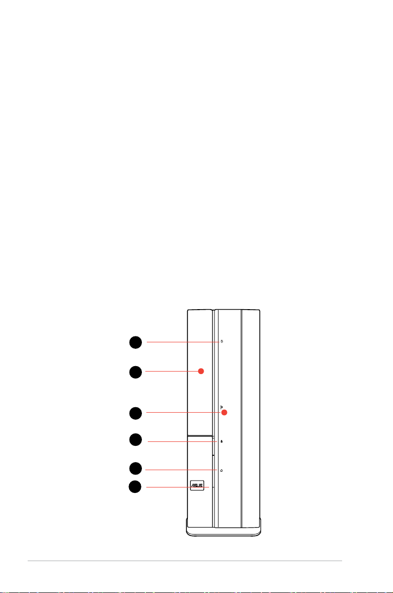
1.2 Front panel
The front panel includes the optical drive bays, power button, and several I/O
ports.
Close
1
2
4
5
6
3
Page 13
1-3ASUS P2-M2A690G
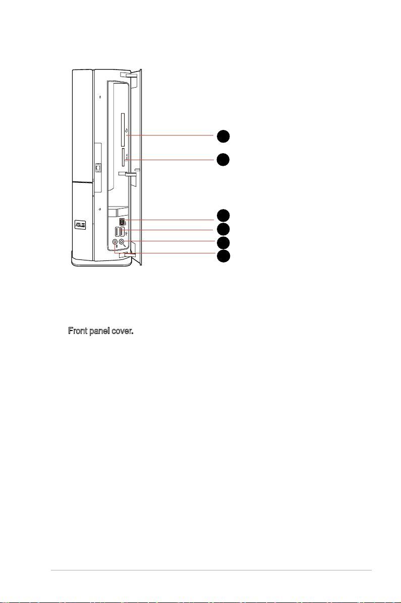
Open
10
11
12
7
8
9
1. HDD LED. This LED lights up when data is read from or written to the hard
disk drive.
2. Optical drive bay cover
3. Front panel cover. Push to open the front panel.
4. Optical drive eject button
5. Power button.
Press this button to turn the system on.
6. Power LED
7. CompactFlashTM Card slot
8. 3 in i card reader
9. 4-pin IEEE 1394 port
10. USB 2.0 ports.
These Universal Serial Bus 2.0 (USB 2.0) ports are available
for connecting USB 2.0 devices such as a mouse, printer, scanner, camera,
PDA, and others.
11. Microphone port (pink).
This port connects a microphone.
12. Headphone port (lime).
This port connects a headphone or a speaker.
Page 14
1-4 Chapter 1: System introduction
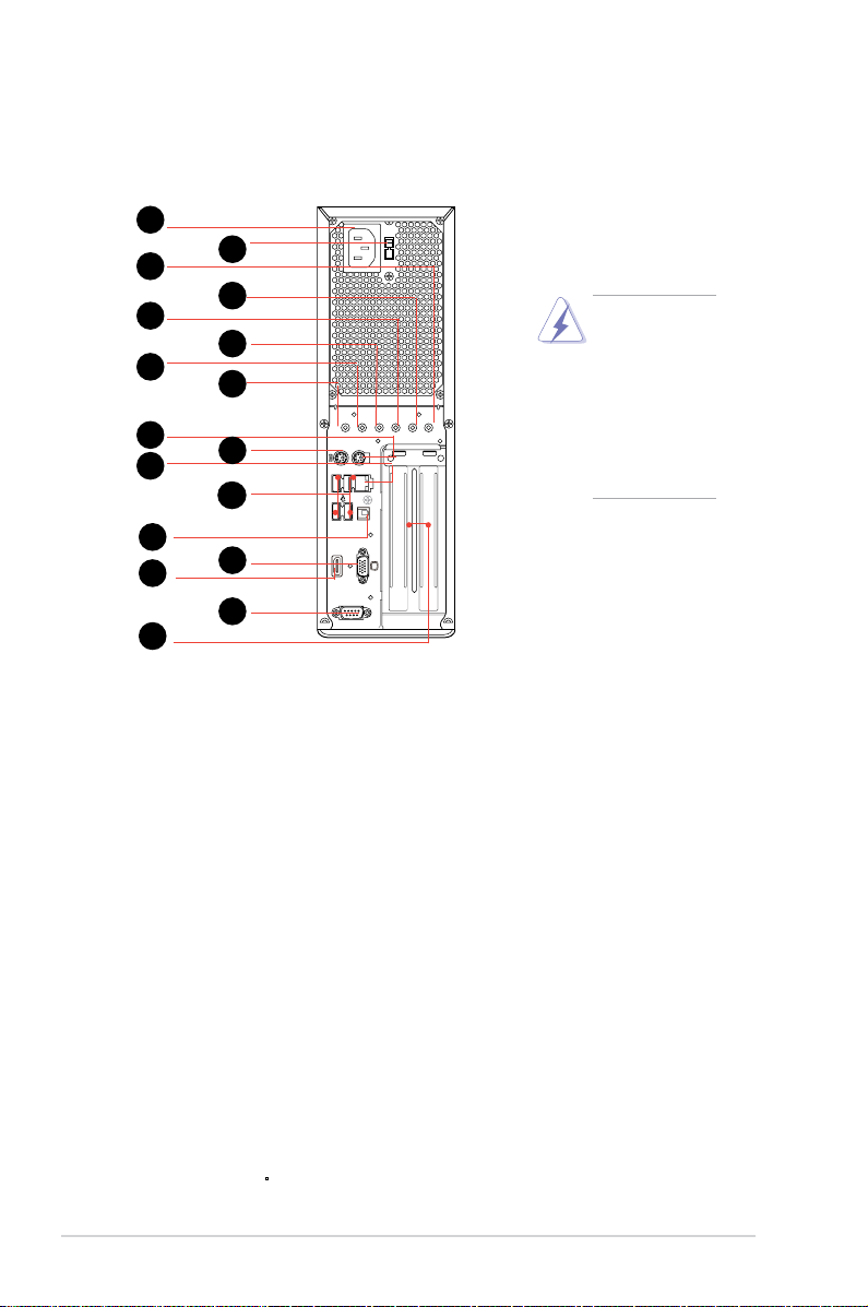
1.3 Rear panel
The system rear panel includes the power connector and several I/O ports that
allow convenient connection of devices.
1. Power connector
2. Voltage selector.
This switch allows you to adjust the system input voltage
according to the voltage supply in your area. If the voltage supply in your
area is 100-127V, set this switch to 115V. If the voltage supply in your area is
200-240V, set this switch to 230V.
3. Center/Sub (yellow orange).
This port connects the center/subwoofer
speakers.
4. Surr-Side (black).
This port connects the side speakers in an 8-channel
audio conguration.
5. Surr-Rear (grey).
This port connects the rear speakers on a 4-channel, 6-
channel, or 8-channel audio conguration.
6. Line In port (light blue).
This port connects the tape, CD, DVD player, or
other audio sources.
7. Line Out port (lime).
This port connects a headphone or a speaker. In 4-
channel and 6-channel conguration, the function of this port becomes Front
Speaker Out.
8. Microphone port (pink).
This port connects a microphone.
9. PS/2 mouse port.
This green 6-pin connector is for a PS/2 mouse.
10. PS/2 keyboard port.
This purple 6-pin connector is for a
PS/2 keyboard.
HDMI
SPDIF-O
KB/MS
1
2
4
5
6
3
10
11
12
7
8
9
14
13
15
16
17
Setting the
switch to 115V
in a 230V
environment or
230V in a 115
environment
will seriously
damage the
system!
Page 15
1-5ASUS P2-M2A690G
11. LAN (RJ-45) port. This port allows Gigabit connection to a Local Area
Network (LAN) through a network hub.
12. USB 2.0 ports 1, 2, 3 and 4.
These 4-pin Universal Serial Bus (USB) ports
are available for connecting USB 2.0 devices.
13.
SPDIF Out port. This port connects an external audio output device via an
optical S/PDIF cable.
14. VGA port
15. HDMI port
16. Serial port
17. PCI slot metal brackets
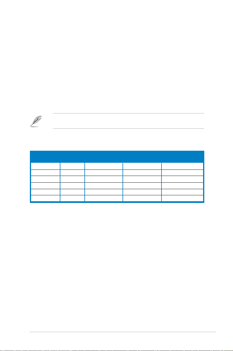
Refer to the audio conguration table below for the function of the audio ports in
2, 4, or 6-channel conguration.
Audio 2, 4, 6 or 8-channel conguration
Light Blue Line In Line In Line In Line In
Lime Line Out Front Speaker Out Front Speaker Out Front Speaker Out
Pink Mic In Mic In Mic In Mic In
Gray • Rear Speaker Out Rear Speaker Out Rear Speaker Out
Black • • • Side Speaker Out
Yellow Orange • • Center/Subwoofer Center/Subwoofer
Port Headset 4-channel 6-channel 8-channel
2-channel
Page 16
1-6 Chapter 1: System introduction
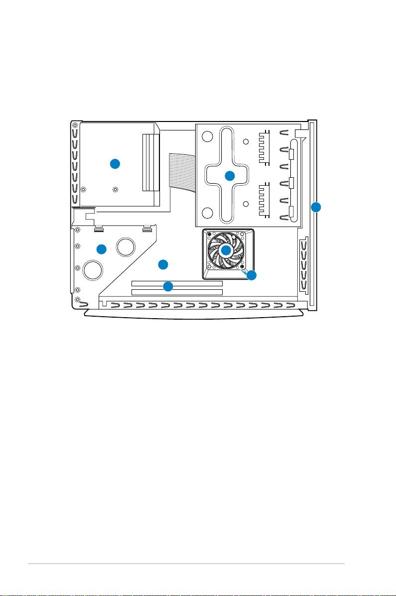
1.4 Internal components
The illustration below is the internal view of the system when you remove the top
cover and the power supply unit. The installed components are labeled for your
reference. Proceed to Chapter 2 for instructions on installing additional system
components.
1. 5.25-inch optical drive and
3.5 inch hard disk drive cage
2. Front panel cover
3. Power supply unit
4. PCI card riser bracket
(connected
to the motherboard PCI slot)
5. ASUS motherboard
6. DIMM sockets
7. AM2 socket
(under the CPU fan
and heatsink assembly)
8. CPU fan and heatsink assembly
1
2
3
4
5
6
8
7
Page 17
Chapter 2
Basic installation
This chapter provides step-by-step
instructions on how to install
components in the system.
Page 18
2-2 Chapter 2: Basic installation
2.1 Preparation
Before you proceed, ensure that you have all the components you plan to install in
the system.
Basic components to install
1. Central Processing Unit (CPU)
2. DDR2 Dual Inline Memory Module (DIMM)
3. Expansion card(s)
4. Hard disk drive
5. Optical drive
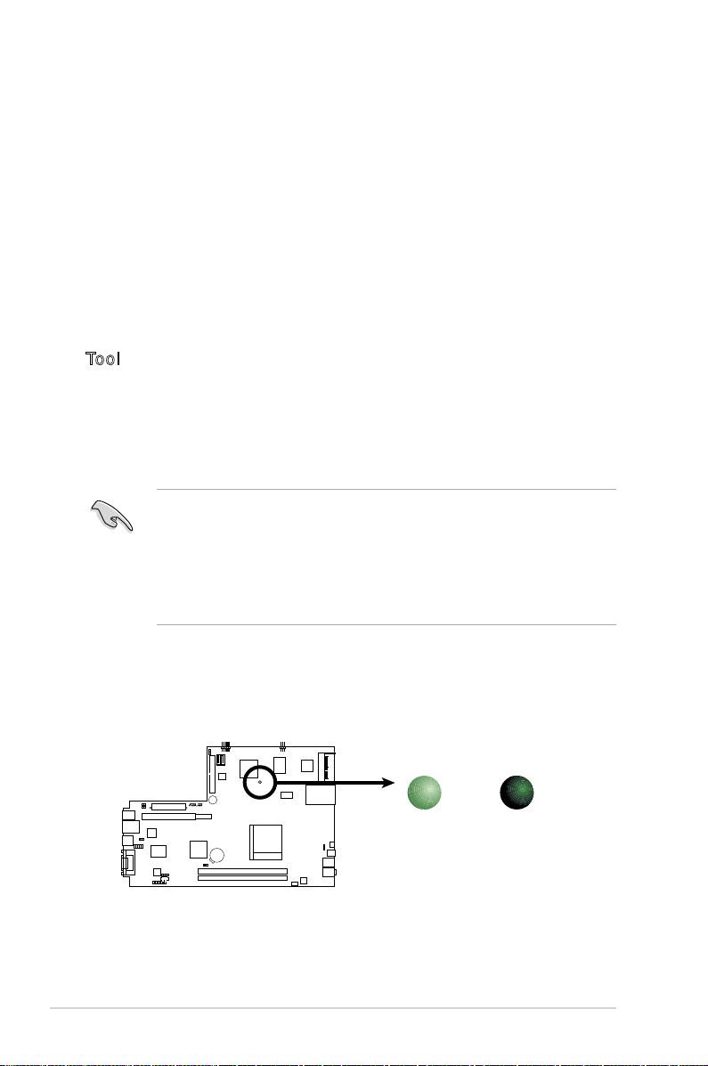
Tool
Phillips (cross) screw driver
The motherboard comes with an onboard standby power LED. This LED lights
up to indicate that the system is ON, in sleep mode or in soft-off mode, and not
powered OFF. Unplug the power cable from the power outlet and ensure that the
standby power LED is OFF before installing any system component.
•
Use a grounded wrist strap or touch a safely grounded object or a metal
object, such as the power supply case, before handling components to
avoid damaging them due to static electricity.
•
Hold components by the edges to avoid touching the ICs on them.
•
Whenever you uninstall any component, place it on a grounded antistatic
pad or in the bag that came with the component.
2.2 Before you proceed
Take note of the following precautions before you install components into the
system.
M2R 68 L
R
M2R68L
Onboard LED
SB_PWR
ON
Standby
Power
OFF
Powered
Off
Page 19
2-3ASUS P2-M2A690G
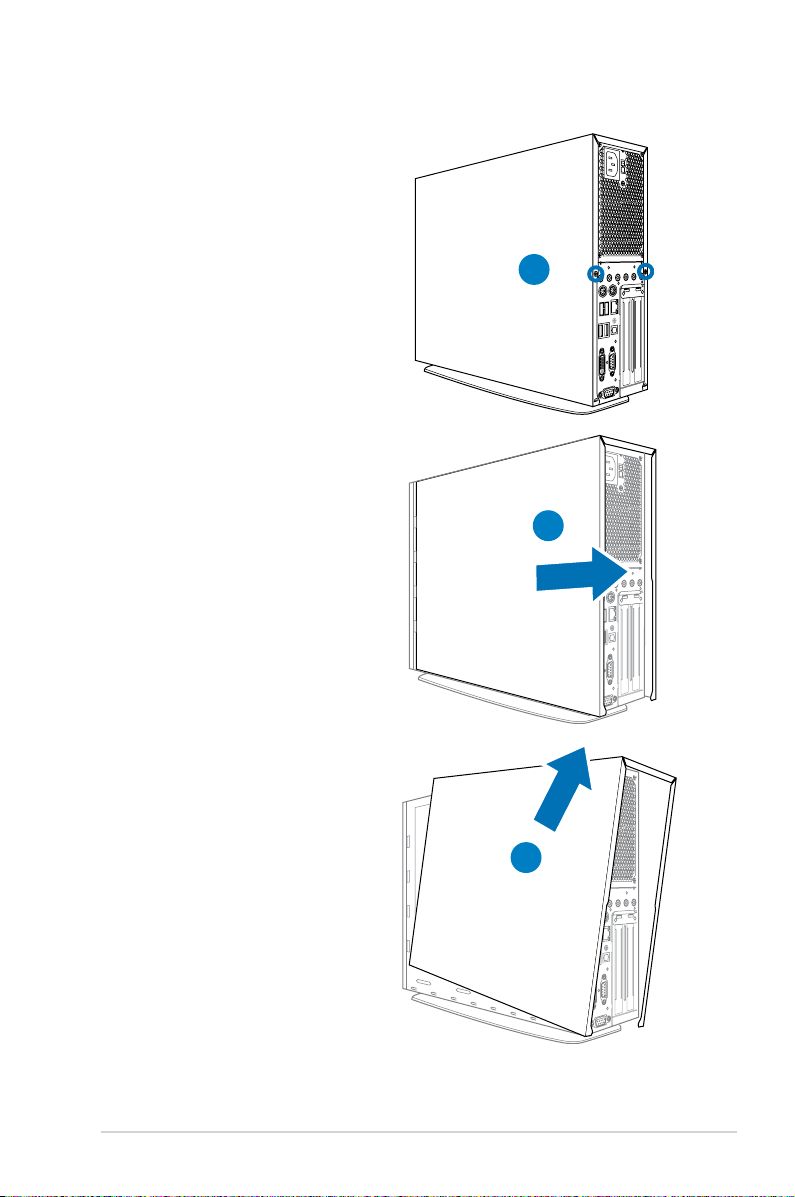
2.3 Removing the side cover
1. Remove the cover screws. Keep
the screws for later use.
2. Pull the cover slightly toward the
rear panel.
3. Lift the cover, then set aside.
1
2
3
Page 20
2-4 Chapter 2: Basic installation
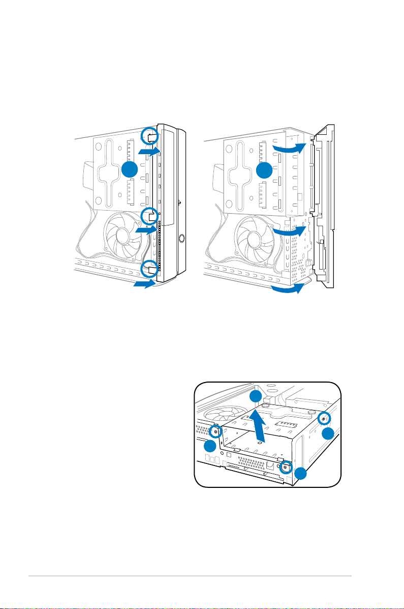
2.4 Removing the front panel cover
1. Lift the front panel cover hooks outward.
2. Carefully remove the front panel cover, then set it aside.
R
2.5 Removing the storage drive assembly
1. Lay the system on its
side, then locate and
remove three storage
drive assembly screws.
2. Lift the storage drive
assembly, then set aside.
1
2
2
1
1
1
Page 21
2-5ASUS P2-M2A690G
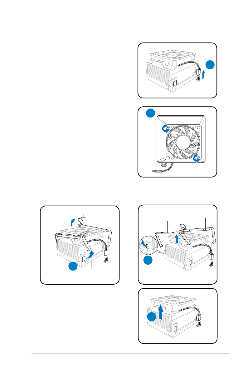
2.6 Removing the CPU fan and heatsink
3. Unhook and slide out the metal
clips that secure the fan and
heatsink assembly to the retention
module.
4. Lift the CPU fan and heatsink
assembly, then set aside.
1. Disconnect the CPU fan cable.
2
3
hook
metal clips
4
retention module
metal
handles
3
1
2. Remove two screws securing the
blower to the CPU fan.
Set the blower aside.
Page 22
2-6 Chapter 2: Basic installation
2.7 Central Processing Unit (CPU)
2.7.1 Overview
The motherboard comes with a 940-pin AM2 socket designed for the AMD
Athlon™ 64 X2 / Athlon™ 64 / Sempron™ processor.
The AM2 socket has a different pinout from the 940-pin socket designed for the
AMD Opteron™ processor. Ensure than you use a CPU that is designed for the
AM2 socket. The CPU ts in only one correct orientation. DO NOT force the
CPU into the socket to prevent bending the pins the CPU!
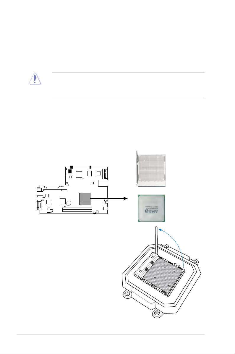
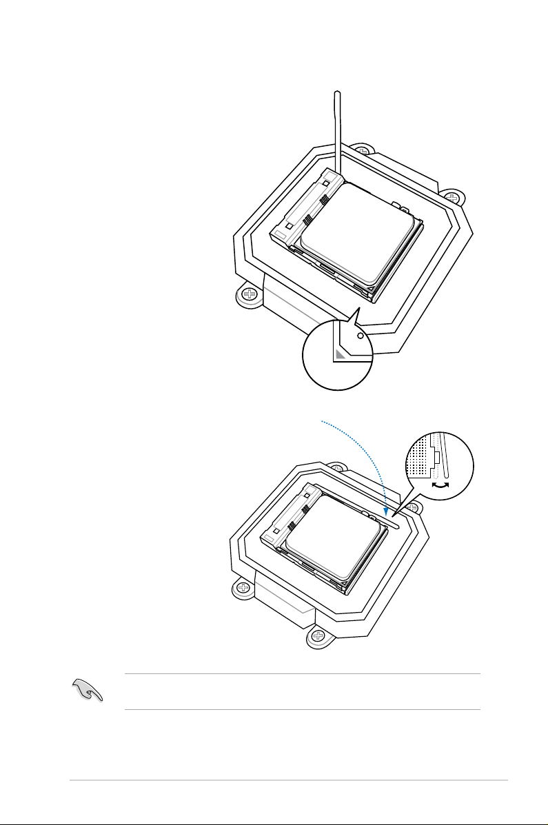
2.7.2 Installing CPU
To install a CPU:
1. Locate the AM2 CPU socket on the motherboard.
2. Press the CPU socket lever
sideways, then lift it up to a
90º-100º angle.
M2R 68 L
R
M2R68L
CPU Socket AM2
Page 23
2-7ASUS P2-M2A690G
3. Match the gold
triangle on the
CPU with the small
triangle on the
socket. Insert the
CPU into the socket
until it ts in place.
4. Push down the
socket lever to
secure the CPU
Ensure to install the CPU fan, blower and heatsink assembly on top of the
installed CPU.
Page 24
2-8 Chapter 2: Basic installation
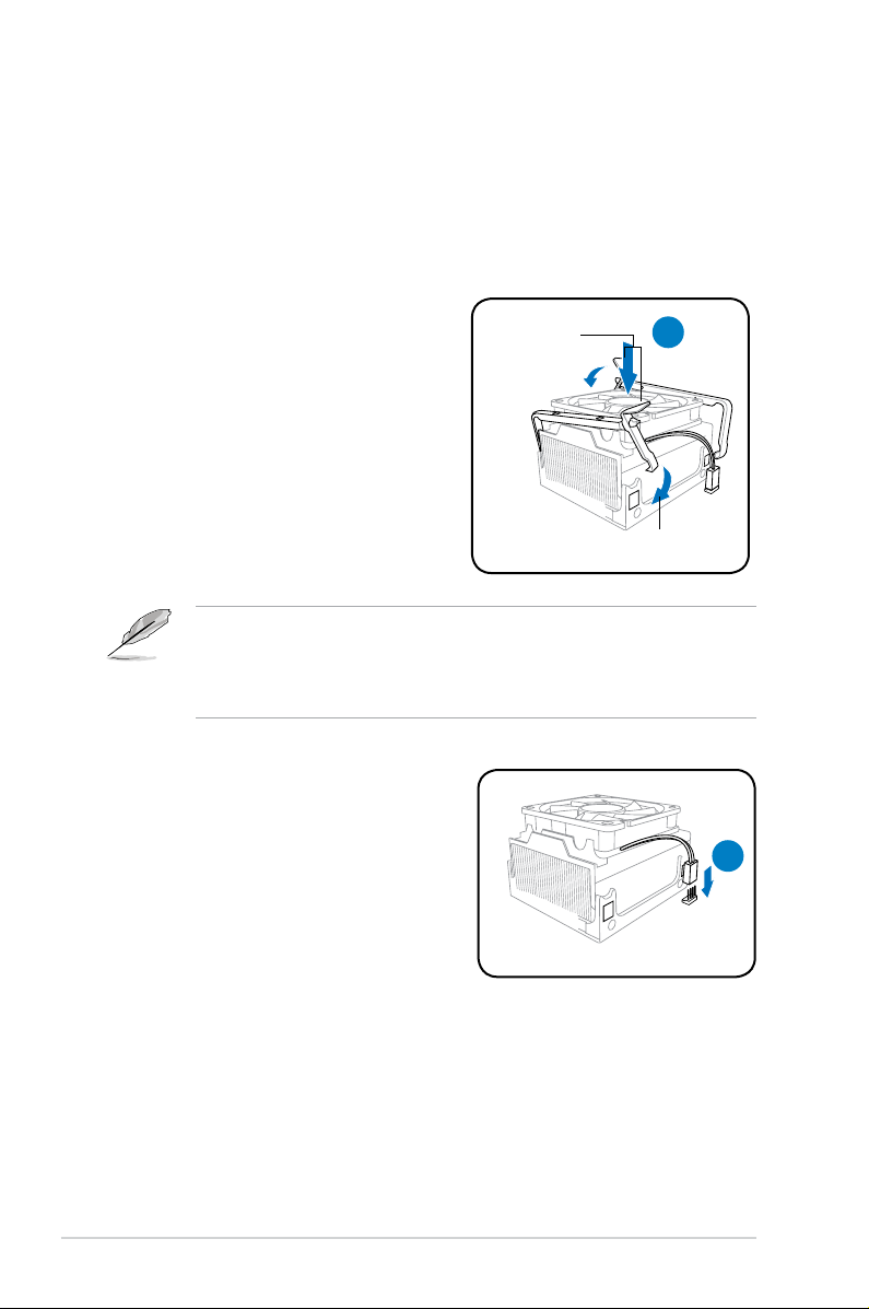
2.7.3 ReInstalling the CPU fan and heatsink assembly
The AMD Athlon™ 64 / AMD Athlon™ 64 X2 / AMD Sempron™ processor requires
a specially designed heatsink and fan assembly to ensure optimum thermal
condition and performance.
Follow these steps to reinstall the CPU fan and heatsink assembly:
• The retention module base is already installed on the motherboard
upon purchase.
• You do not have to remove the retention module base when installing the
CPU or installing other motherboard components.
2. Connect the CPU cable to the CPU fan
connector on the motherboard.
retention module
metal handles
1
2
1. Position the CPU fan and heatsink
assembly on top of the installed
CPU.
Page 25
2-9ASUS P2-M2A690G
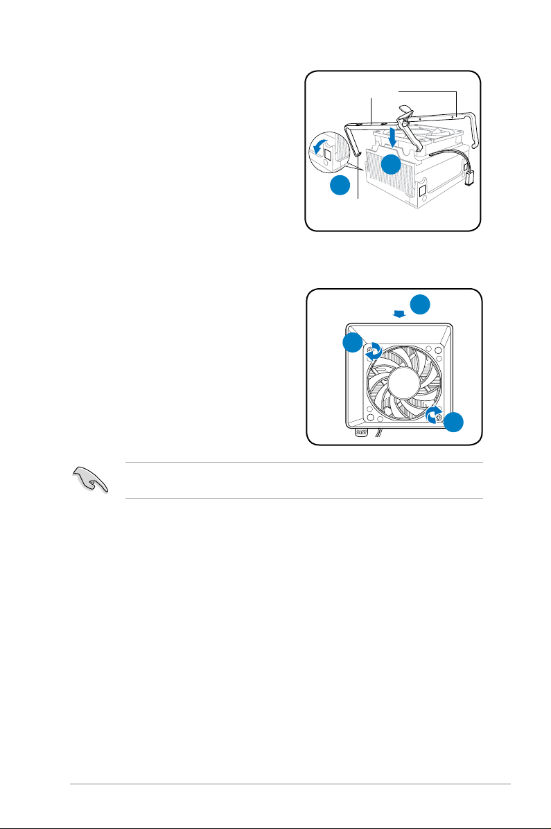
3. Align the metal clips to the side rail of
the CPU fan and heatsink assembly,
with the locking levers in the reverse
orientation.
4. Snap the hook of each metal clip into
the hold of the retention module.
5. Carefully press down the locking lever
and hook its end into the retention
module.
Do not forget to connect the CPU fan connector! Hardware monitoring errors
can occur if you fail to plug this connector.
4
3
hook
metal clips
6. Position the blower on top of the CPU
fan and heatsink assembly.
7. Secure the blower to the CPU fan and
heatsink assembly with the screws
you removed earlier.
6
7
7
Page 26

2-10 Chapter 2: Basic installation
2.8 Installing a DIMM
The system motherboard comes with two Double Data Rate 2 (DDR2) Dual Inline
Memory Module (DIMM) sockets.
The following gure illustrates the location of the sockets:
• Install only identical (the same type and size) DDR2 memory modules.
• Install only ASUS-certied memory modules. Refer to the DDR2 Qualied
Vendors List (QVL) on the next page for details. Visit the ASUS website for
the latest DDR2 QVL.
• Always install DIMMs with the same CAS latency. For optimum
compatibility, we recommend that you obtain memory modules from the
same vendor.
2.8.1 Memory congurations
You may install up to 4 GB system memory using 256 MB, 512 MB, 1 GB, and
2 GB DDR2 DIMMs.
M2R 68 L
R
M2R68L 2
40-pin DDR2 DIMM Sockets
DIMM_B1
DIMM_A1
128 Pins
112 Pins
DIMM Support
Page 27

2-11ASUS P2-M2A690G
Qualied Vendors Lists (QVL)
DDR2-667
DDR2-800
Size Vendor Model CL Brand SS / D S C o m p o n e n t A B
DIMM Support
Size Ve n d o r M o d e l CL Brand S S/DS Co m p o n e n t A B
DIMM Support
256MB Kingston KVR667D2N5/256 N/A Elpida SS E2508AB-6E-E • •
512MB Kingston KVR667D2N5/512 N/A Kingston SS D6408TE8WL-27 • •
1G Kingston KVR667D2N5/1G N/A Kingston DS D6408TE8WL-3 • •
512MB Samsung KR M378T6553CZ0-CE6 N/A Samsung SS K4T51083QC • •
512MB Samsung KR M378T6453FZ0-CE6 N/A Samsung DS K4T56083QF-ZCE6 • •
512MB Samsung M378T6553CZ3-CE6 N/A Samsung SS K4T51083QC-ZCE6 • •
1G Samsung M378T2953CZ3-CE6 N/A Samsung DS K4T51083QC-ZCE6 • •
1G Samsung KR M378T2953CZ0-CE6 N/A Samsung DS K4T51083QC-ZCE6 • •
256MB Qimonda HYS64T32000HU-3S-A N/A Qimonda SS HYB18T512160AF-3SSSS17310 • •
512MB Kingston KVR800D2N5/512 N/A Samsung SS K4T51083QC-ZCE7 • •
512MB Kingston KVR800D2N5/512 N/A Promos SS V59C1512804QBF25S0054707PEBPA • •
1G Kingston KVR800D2N5/1G N/A Samsung DS K4T51083QC-ZCE7 • •
1G Kingston KHX6400D2LL/1G N/A Kingston DS Heat-Sink Package • •
1G Kingston KVR800D2N5/1G N/A Nanya DS NT5TU64M8BE-25C62321800CP • •
512MB Samsung KR M378T6553CZ3-CE7 N/A Samsung SS K4T51083QC-ZCE7 • •
1G Samsung KR M378T2953CZ3-CE7 N/A Samsung DS K4T51083QC-ZCE7 • •
256MB Qimonda HYS64T32001HU-2.5-A N/A Qimonda SS HYB18T256800AF25SSS49313 • •
512MB Qimonda HYS64T64020HU-2.5-A N/A Qimonda DS HYB18T256800AF25SSS25063 •
512MB Corsair CM2X512A-6400 5 Corsair SS Heat-Sink Package • •
1G Corsair CM2X1024-6400 5 Corsair DS Heat-Sink Package •
512MB HY HYMP564U64AP8-S6 AA N/A Hynix SS HY5PS12821AFP-S6 • •
512MB HY HYMP564U64BP8-S5 AB N/A Hynix SS HY5PS12821BFP-S5 • •
512MB HY HYMP564U64CP8-S5 AB 5 Hynix SS HY5PS12821CFP-S5 •
1G HY HYMP512U64AP8-S6 AA N/A Hynix DS HY5PS12821AFP-S6 • •
1G HY HYMP512U64BP8-S5 AB 5 Hynix DS HY5PS12821BFP-S5 • •
1G HY HYMP512U64CP8-S5 AB 5 Hynix DS HY5PS12821CFPS5 • •
512MB VDATA M2GVD6G3H3160I1E53 N/A VDATA SS VD29608A8A-25EG30648 • •
1G VDATA M2GVD6G3I4170I1E53 N/A VDATA DS VD29608A8A-25EG30647 • •
512MB PSC AL6E8E63B-8E1K 5 PSC SS A3R12E3HEF641B9A05 • •
1G PSC AL7E8E63B-8E1K 5 PSC DS A3R12E3HEF641B9A05 • •
512MB AENEON AET660UD00-25DB98X N/A AENEON SS AET93F25DB 0621 • •
1G AENEON AET760UD00-25DB97X 5 AENEON DS AET93R25DB 0640 • •
512MB SIS SLY264M8-JGE-3 N/A SIS SS DDRII6408-8E 7212 • •
1G SIS SLY264M8-JGE-3 N/A SIS DS DDRII6408-8E 7301 • •
512MB TAKEMS TMS51B264C081-805EP 5 takeMS SS MS18T51280-2.5P0710
1G TAKEMS TMS1GB264C081-805AE 5 takeMS DS MS18T51280-25FEA0709A
1G TAKEMS TMS1GB264C081-805EP 5 takeMS DS MS18T51280-2.5P0716 • •
512MB VERITECH GTU512HLTXX4EG N/A Veritech SS VTD264M8PC4G03A169045648 • •
1G VERITECH GTU01GHLTXX4EG N/A Veritech DS VTD264M8PC4G03A169045648
1G UMAX 1GB,DDR2,PC6400 5 UMAX DS U2S12D30TP-8E • •
Page 28

2-12 Chapter 2: Basic installation
Size Vendor M odel C L Brand S S / D S Co m p o n e n t A B
DIMM Support
DDR2-667
512MB Qimonda HYS64T32000HU-3S-A N/A Qimonda SS HYB18T5128000AF-3SSSS27416 •
512MB Qimonda HYS64T64000HU-3S-A N/A Qimonda SS HYB18T512800AF3SFSS05346 • •
1G Qimonda HYS64T128020HU-3S-A N/A Qimonda DS HYB18T512800AF3SSSS28104 • •
512MB Corsair VS512MB667D2 N/A Corsair DS MIII0052532M8CEC • •
512MB Corsair CM2X512-5400C4 4 Corsair SS Heat-Sink Package • •
1G Corsair VS1GB667D2 N/A Corsair DS MID095D62864M8CEC • •
256MB HY HYMP532U64CP6-Y5 AB 5 Hynix SS HY5PS121621CFP-Y5 • •
512MB HY HYMP564U64AP8-Y4 AA N/A Hynix SS HY5PS12821AFP-Y4 • •
512MB HY HYMP564U64AP8-Y5 AA N/A Hynix SS HY5PS12821AFP-Y5 • •
1G HY HYMP512U64AP8-Y5 AB N/A Hynix DS HY5PS12821AFP-Y5 • •
1G HY HYMP512U64CP8-Y5 AB 5 Hynix DS HY5PS12521CFP-Y5 • •
512MB Kingmax KLCC28F-A8EB5 N/A Elpida SS E5108AE-6E-E • •
v512MB Kingmax KLCC28F-A8KB5 N/A Kingmax SS KKEA88B4LAUG-29DX • •
1G Kingmax KLCD48F-A8KB5 N/A Kingmax DS KKEA88B4LAUG-29DX • •
512MB Apacer 78.91092.420 N/A Elpida SS E5108AE-6E-E • •
512MB Apacer AU512E667C5KBGC 5 Apacer SS AM4B5708MIJS7E0627B • •
512MB Apacer AU512E667C5KBGC 5 Apacer SS AM4B5708GQJS7E06332F • •
1G Apacer AU01GE667C5KBGC N/A Apacer DS AM4B5708GQJS7E0636B • •
1G Apacer 78.01092.420 5 Elpida DS E5108AE-6E-E • •
1G Apacer AU01GE667C5KBGC 5 Apacer DS AM4B5708MIJS7E0627B • •
512MB ADATA M20EL5G3H3160B1C0Z N/A Elpida SS E5108AE-6E-E • •
512MB ADATA M20AD5G3H3166I1C52 N/A ADATA SS AD29608A8A-3EG20648 • •
1G ADATA M2OAD5G3I4176I1C52 N/A ADATA DS AD29608A8A-3EG20645 • •
512MB VDATA M2GVD5G3H31A4I1C52 N/A VDATA SS VD29608A8A-3EC20615 • •
512MB VDATA M2YVD5G3H31P4I1C52 N/A VDATA SS VD29608A8A-3EG20627 • •
512MB VDATA M2GVD5G3H166I1C52 N/A VDATA SS VD29608A8A-3EG20637 • •
1G VDATA M2GVD5G3I41P6I1C52 N/A VDATA DS VD29608A8A-3EG20627 • •
1G VDATA M2GVD5G3I41C4I1C52 N/A VDATA DS VD29608A8A-3EC20620 • •
1G VDATA M2GVD5G3I4176I1C52 N/A VDATA DS VD29608A8A-3EG20641 • •
512MB PSC AL6E8E63B-6E1K 5 PSC SS A3R12E3GEF637BLC5N • •
1G PSC AL7E8E63B-6E1K 5 PSC DS A3R12E3GEF637BLC5N • •
256MB Nanya NT256T64UH4A1FY-3C N/A Nanya SS NT5TU32M16AG-3C • •
512MB Nanya NT512T64U88A1BY-3C N/A Nanya SS NT5TU64M8AE-3C • •
512MB MDT MDT 512MB 4 MDT SS 18D51280D-30648 • •
1G MDT MDT 1024MB 4 MDT DS 18D51200D-30646 • •
1G MDT MDT 1024MB 4 MDT DS 18D51280D-30646E • •
1G PQI DDR2-667U 1G N/A Hynix DS HY5PS12821BFP-E3 A • •
512MB AENEON AET660UD00-30DA98Z N/A AENEON SS AET93F30DA 0552 • •
512MB AENEON AET660UD00-30DB97X 5 AENEON SS AET93R300B 0634 • •
1G AENEON AET760UD00-30DA98Z N/A AENEON DS AET93F30DA8EE47414G 0540 • •
512MB AENEON AET660UD00-30DA98Z N/A AENEON SS AET93F300A 0606 • •
1G AENEON AET760UD00-30DA98Z N/A AENEON DS AET93F30DA 0604 • •
1G AENEON AET760UD00-30DB97X 5 AENEON DS AET93R300B 0639 • •
512MB TAKEMS TMS51B264C081-665QI 5 takeMS SS MS18T51280-3 • •
512MB TAKEMS TMS51B264C081-665AP 5 takeMS SS MS18T51280-3S0627D •
1G TAKEMS TMS1GB264C081-665QI 5 takeMS DS MS18T51280-3 • •
Page 29
2-13ASUS P2-M2A690G
DDR2-533
Size Ve n d o r Model CL B r a n d SS / D S Co m p o n e n t A B
DIMM Support
256MB Kingston KVR533D2N4/256 N/A Elpida SS E5116AB-5C-E • •
256MB Kingston KVR533D2N4/256 N/A Elpida SS E5116AF-5C-E • •
512MB Kingston KVR533D2N4/512 N/A Hynix DS HY5PS56821F-C4 • •
512MB Kingston KVR533D2N4/512 N/A Inneon SS HYB18T512800AF3733336550 • •
1G Kingston KVR533D2N4/1G N/A Kingston DS D6408TE7BL-37 • •
256MB Samsung M378T3253FG0-CD5 N/A Samsung SS K4T56083QF-GCD5 • •
512MB Samsung M378T6553BG0-CD5 4 Samsung SS K4T51083QB-GCD5 • •
256MB Qimonda HYS64T32000HU-3.7-A 4 Qimonda SS HYB18T512160AF-3.7AFSS31270 • •
512MB Qimonda HYS64T64000GU-3.7-A 4 Qimonda SS HYB18T512800AC37SSS11511 • •
512MB Qimonda HYS64T64000HU-3.7-A N/A Qimonda SS HYB18T512800AF37SSS12079 • •
512MB Qimonda HYS64T64000HU-3.7-A N/A Qimonda SS HYB18T512800AF37FSS29334 • •
256MB HY HYMP532U64CP6-C4 AB 4 Hynix SS HY5PS121621CFP-C4 • •
1G HY HYMP512U64CP8-C4 AB 4 Hynix DS HY5PS12821CFP-C4 • •
512MB Micron MT 16HTF6464AG-53EB2 4 Micron DS D9BOM • •
512MB Micron MT 16HTF6464AG-53EB2 4 Micron DS Z9BQT • •
1G Micron MT 16HTF12864AY-53EA1 4 Micron DS D9CRZ • •
512MB Corsair VS512MB533D2 N/A Corsair DS MIII0052532M8CEC • •
512MB Elpida EBE51UD8ABFA-5C-E N/A Elpida SS E5108AB-5C-E • •
512MB Kingmax KLBC28F-A8KB4 N/A Kingmax SS KKEA88B4IAK-37 • •
256MB Kingmax KLBB68F-36EP4 N/A Elpida SS E5116AB-5C-E • •
512MB Kingmax KLBC28F-A8EB4 N/A Elpida SS E5108AE-5C-E • •
512MB PQI MEAB-323LA N/A PQI SS D2-E04180W025 • •
1G PQI MEAB-423LA N/A PQI DS D2-E04230W107
512MB AENEON AET660UD00-370A98Z 4 AENEON SS AET93F370A G 0513 • •
256MB AENEON AET560UD00-370A98Z 4 AENEON SS AET94F370AWVV34635G0520
512MB AENEON AET660UD00-370A98Z 4 AENEON SS AET93F370A 3VV36328G 0522
512MB AENEON AET660UD00-370A98X N/A AENEON SS AET93F370A 0518 • •
512MB AENEON AET660UD00-370A88S N/A AENEON DS AET82F370A 0550 •
1G TAKEMS TMS1GB264C081-665AE 5 takeMS DS MS18T51280-3SEA07100 •
1G TAKEMS TMS1GB264C081-665AP 5 takeMS DS MS18T51280-3SP0717A • •
512MB VERITECH GTP512HLTM45EG N/A VERITECH SS VTD264M8PC6G01A164129621 • •
1G VERITECH GTP01GHLTM55EG N/A VERITECH DS VTD264M8PC6G01A164129621 • •
512MB GEIL GX21GB5300DC 4 GEIT SS Heat-Sink Package
512MB TEAM TVDD512M667C5 N/A TEAM SS T2D648MT-6 • •
1G TEAM TVDD1.02M667C4 N/A TEAM DS T2D648PT-6 • •
512MB Century CENTURY 512MB N/A Nanya SS NT5TU64M8AE-3C •
512MB Century CENTURY 512MB N/A Hynix SS HY5PS12821AFP-Y5
1G Century CENTURY 1G N/A Hynix DS HY5PS12821AFP-Y5 •
1G Century CENTURY 1G N/A Nanya DS NT5TU64M8AE-3C • •
512MB KINGBOX 512MB 667MHz N/A KINGBOX SS EPD264082200-4 •
1G KINGBOX DDRII 1G 667MHz N/A KINGBOX DS EPD264082200-4 •
DDR2-667
Size Vendor Mo del C L Br a n d SS / D S Component A B
DIMM Support
Page 30

2-14 Chapter 2: Basic installation
Side(s): SS - Single-sided
DS
- Double-sided
CL: CAS Latency
DIMM support:
A - Supports one module inserted into either slot, in Single-channel memory
conguration.
B - Supports one pair of modules inserted into both slots as one pair of Dual-
channel memory conguration.
DDR2-533
Size Ve n d o r M o d e l CL B r a n d S S / D S C o m p o n e n t A B
DIMM Support
512MB AENEON AET660UD00-370B97X 4 AENEON SS AET93R370B 0640 • •
1G AENEON AET760UD00-370A98Z N/A AENEON DS AET93F370A 0551 • •
1G AENEON AET760UD00-370A98S N/A AENEON DS AET92F370A 0606 •
1G AENEON AET760UD00-370B97X 4 AENEON DS AET93R370B 0640 • •
1G AENEON AET760UD00-370B97S 4 AENEON DS AET92R370B 0644 • •
2G AENEON AET860UD00-370A08X N/A AENEON DS AET03F370AFVV26176G 0542 •
256MB TAKEMS TMS25B264B161-534KQ 4 takeMS SS MS18T51216-3.70711 •
512MB TAKEMS TMS51B264C081-534QI 4 takeMS SS MS18T51280-3.7 • •
512MB TAKEMS TMS51B264C081-534AP 4 takeMS SS MS18T51280-3.7P0704D • •
v512MB TAKEMS TMS51B264C081-534AE 4 takeMS SS MS18T51280-3.7EA07100 • •
1G TAKEMS TMS1GB264C081-534AE 4 takeMS DS MS18T51280-3.7EA0651D
1G TAKEMS TMS1GB264C081-534QI 4 takeMS DS MS18T51280-3.7 • •
1G TAKEMS TMS1GB264C081-534AP 4 takeMS DS MS18T51280-3.7P0645D •
512MB REMAXEL RML1040EG38D6F-533 4 Elpida SS E5108AG-5C-E •
512MB VERITECH GTP512HLTM46DG N/A VERITECH SS VTD264M8PC6G01A164129621 • •
1G VERITECH GTP01GHLTM56DG N/A VERITECH DS VTD264M8PC6G01A164129621 • •
Page 31

2-15ASUS P2-M2A690G
2.8.3 Removing a DDR2 DIMM
Follow these steps to remove a DIMM:
1. Simultaneously press the
retaining clips outward to unlock
the DIMM.
2. Remove the DIMM from the socket.
Support the DIMM lightly with your ngers when pressing the retaining clips.
The DIMM might get damaged when it ips out with extra force.
2.8.2 Installing a DDR2 DIMM
3. Firmly insert the DIMM into the
socket until the retaining clips snap
back in place and the DIMM is
properly seated.
1. Unlock a DDR2 DIMM socket
by pressing the retaining clips
outward.
2. Align a DIMM on the socket
such that the notch on the DIMM
matches the break on the socket.
Locked Retaining Clip
Ensure to unplug the power supply before adding or removing DIMMs or other
system components. Failure to do so may cause severe damage to both the
motherboard and the components.
A DDR2 DIMM is keyed with a notch so that it ts in only one direction. DO
NOT force a DIMM into a socket to avoid damaging the DIMM.
DDR2 DIMM notch
1
2
1
3
Unlocked retaining clip
1
1
DDR2 DIMM notch
2
Page 32

2-16 Chapter 2: Basic installation
2.9 Expansion slots
In the future, you may need to install expansion cards. The following sub-sections
describe the slots and the expansion cards that they support.
Ensure to unplug the power cord before adding or removing expansion cards.
Failure to do so may cause you physical injury and damage to the motherboard
components.
2.9.1 PCI slot
This system has one PCI slot that supports cards such as a LAN card, SCSI card,
USB card, and other cards that comply with PCI specications.
2.9.3 Installing an expansion card
1. Lift the PCI riser card assembly.
2.9.2 PCI Express x1 slot
This system has one PCI Express x1 slot that supports cards such as a PCI
Express x1 network card, SCSI card, and other cards that comply with the PCI
Express specications.
Page 33

2-17ASUS P2-M2A690G
2. Remove the metal cover opposite the slot that you intend to use.
3. Insert the card connector to the slot, then press the card rmly until it ts in
place. Secure the card with a screw.
4. Reinstall the PCI riser card assembly. Ensure that the riser card connector sits
properly on the motherboard PCI slot.
Page 34

2-18 Chapter 2: Basic installation
2.10 Installing an optical drive
Follow these steps to install an optical drive:
1. Turn the storage drive assembly upside down with the 3.5-inch bay on top of
the 5.25-inch bay.
2. Insert the optical drive upside down to the 5.25-inch bay, then secure it with
two screws on both sides.
3. Turn the storage drive assembly, insert the hard disk drive upside down to the
3.5-inch bay, then secure it with two screws on both sides.
2
3
Page 35

2-19ASUS P2-M2A690G
2.11 Reinstalling the storage drive
assembly
Before reinstalling the storage drive assembly, connect the IDE / SATA and power
plugs to the IDE / SATA and power connectors at the back of the drives.
1. Connect the black plug of the IDE cable to the optical drive, then the gray
plug to the hard disk drive. If you have the SATA HDD, connect the SATA
cable to the SATA HD.
2. Connect the 4-pin power plugs to the power connectors at the back of the
drives.
3. Install the storage drive assembly to the chassis.
4. Secure the storage drive assembly with three screws.
R
3
R
4
Page 36

2-20 Chapter 2: Basic installation
2.12 Installing the foot stand
2.13 Reinstalling the front panel cover and
the cover
1. Match the foot stand
hooks to the holes on the
chassis.
2. Pull the foot stand to the
direction of the arrow
until the lock clicks in
place.
To remove the foot stand, lift the lock, then slightly push the foot stand to the
direction of the rear panel until it disengages from the chassis.
Refer to the section of Removing the front panel cover and follow the instructions
in reverse.
Refer to the section of Removing the cover and follow the instructions in reverse.
Page 37

ASUS P2-M2A690G
Chapter 3
Starting up
This chapter helps you power up the
system and install drivers and utilities
from the support CD.
Page 38

3-2 Chapter 3: Starting up
3.1 Installing an operating system
The barebone system supports Windows® 2000 / XP / Vista Operating Systems
(OS). Always install the latest OS version and corresponding updates so you can
maximize the features of your hardware.
3.3 Support CD information
The support CD that came with the system contains useful software and several
utility drivers that enhance the system features.
3.2 Powering up
Press the system power button ( ) to enter the OS.
Press to turn ON the system
Because motherboard settings and hardware options vary, use the setup
procedures presented in this chapter for general reference only. Refer to your
OS documentation for more information.
•
Screen display and driver options may not be the same for different
operating system versions.
•
The contents of the support CD are subject to change at any time without
notice. Visit the ASUS website for updates.
Page 39

3-3ASUS P2-M2A690G
3.3.1 Running the support CD
To begin using the support CD, place the CD in your optical drive. The CD
automatically displays the Drivers menu if Autorun is enabled in your computer.
If Autorun is NOT enabled in your computer, browse the contents of the
support CD to locate the le ASSETUP.EXE from the BIN folder. Double-click
the ASSETUP.EXE to run the CD.
Click an item to install
Click an icon to display
support CD/motherboard
information
ASUS InstALL - Installation Wizard for Drivers
Automatically installs all the necessary drivers for this motherboard.
Attansic L1 Gigabit Ethernet Driver
Installs the Attansic L1 Gigabit Ethernet driver.
ATI Display Driver
Installs the ATI display driver.
Realtek Audio Driver
Allows you to install the Realtek audio driver.
ATI HDMI Driver
Installs the ATI HDMI.
Page 40

3-4 Chapter 3: Starting up
3.3.2 Utilities menu
The Utilities menu shows the applications that the motherboard supports.
ASUS InstAll - Installation Wizard for Utilities
Installs the ASUS InstAll - Installation Wizard Utilities.
ASUS Update
The ASUS Update utility allows you to update the motherboard BIOS in a Windows®
environment. This utility requires an Internet connection either through a network or an
Internet Service Provider (ISP).
ASUS Screen Saver
Installs ASUS Screen Saver.
ASUS Cool’n’Quiet Utility
Installs the ASUS Cool’n’Quiet Utility.
ASUS PC Probe II
This smart utility monitors the fan speed, CPU temperature, and system voltages, and
alerts you of any detected problems. This utility helps you keep your computer in healthy
operating condition.
Page 41

3-5ASUS P2-M2A690G
3.3.4 ASUS Contact information
Click the Contact tab to display the ASUS contact information. You can also nd
this information on the inside front cover of this user guide.
3.3.3 Make disk menu
The Make disk menu shows the drivers that the motherboard supports.
Make ATI RAID/AHCI x86_x64_WinXP Driver
Allows you to make ATI RAID/AHIC x86_x64_WinXP driver.
Make ATI RAID/AHCI Vista32 Driver
Allows you to make ATI RAID/AHCI Vista32 driver.
Make ATI RAID/AHCI Vista64 Driver
Allows you to make ATI RAID/AHCI Vista64 driver.
Page 42

3-6 Chapter 3: Starting up
Installing PC Probe II
To install PC Probe II on your computer:
1. Place the support CD to the optical drive. The
Drivers installation tab
appears if your computer has an enabled Autorun feature.
Click to close the
Preference panel
2. Click the Utilities tab, then click ASUS PC Probe II.
3. Follow the screen instructions to complete installation.
Launching PC Probe II
You can launch the PC Probe II right after installation or anytime from the
Windows® desktop.
To launch the PC Probe II from the Windows® desktop, click Start > All Programs
> ASUS > PC Probe II. The PC Probe II main window appears.
After launching the application, the PC Probe II icon appears in the Windows®
taskbar. Click this icon to close or restore the application.
Using PC Probe II
Main window
The PC Probe II main window allows
you to view the current status of
your system and change the utility
conguration. By default, the main
window displays the Preference
section. You can close or restore the
Preference section by clicking on
the triangle on the main window right
handle.
If Autorun is not enabled in your computer, browse the contents of the support
CD to locate the setup.exe le from the ASUS PC Probe II folder. Double-click
the setup.exe le to start installation.
3.4 Software information
Most of the applications in the support CD have wizards that will conveniently
guide you through the installation. View the online help or readme le that came
with the software for more information.
ASUS PC Probe II
ASUS PC Probe II is a utility that monitors the computer’s vital components
and alerts you of any problem with these components. PC Probe II senses fan
rotations, CPU temperature, and system voltages, among others. PC Probe II
is software-based, allowing you to start monitoring your computer the moment
you turn it on. With this utility, you are assured that your computer is always in a
healthy operating condition.
Page 43

3-7ASUS P2-M2A690G
Button Function
Opens the Conguration window
Opens the
Report window
Opens the
Desktop Management Interface window
Opens the
Peripheral Component Interconnect window
Opens the
Windows Management Instrumentation window
Opens the hard disk drive, memory, CPU usage window
Shows/Hides the
Preference section
Minimizes the application
Closes the application
Sensor alert
When a system sensor detects a problem, the main window right handle turns red,
as the illustrations below show.
When displayed, the monitor panel for that sensor also turns red. Refer to the
Monitor panels section for details.
Preferences
You can customize the application using the
Preference section in the main window. Click
the box before each preference to activate or
deactivate.
Page 44

3-8 Chapter 3: Starting up
Hardware monitor panels
The hardware monitor panels display the current value of a system sensor such as
fan rotation, CPU temperature, and voltages.
The hardware monitor panels come in two display modes: hexagonal (large) and
rectangular (small). When you check the Enable Monitoring Panel option from
the Preference section, the monitor panels appear on your computer’s desktop.
Changing the monitor panels position
To change the position of the monitor panels on the desktop, click
the arrow down button of the Scheme options, then select another
position from the list box. Click OK when nished.
Moving the monitor panels
All monitor panels move together using a magnetic effect. If you want
to detach a monitor panel from the group, click
the horseshoe magnet icon. You can now move
or reposition the panel independently.
Adjusting the sensor threshold value
You can adjust the sensor threshold value in
the monitor panel by clicking the arrow buttons. You can also adjust the threshold
values using the Cong window.
You cannot adjust the sensor threshold
values in a small monitoring panel.
Large display
Small display
Click to
increase value
Click to
decrease
value
Page 45

3-9ASUS P2-M2A690G
Monitoring sensor alert
The monitor panel turns red when a component value exceeds or is lower than the
threshold value. Refer to the illustrations below.
Large display
Small display
WMI browser
Click to display the Windows
Management Instrumentation (WMI)
browser. This browser displays various
Windows® management information.
Click an item from the left panel to
display on the right panel. Click the
plus sign (+) before WMI Information
to display the available information.
You can enlarge or reduce the browser size by dragging the bottom right corner
of the browser.
DMI browser
Click to display the Desktop
Management Interface (DMI) browser.
This browser displays various desktop
and system information. Click the plus
sign (+) before DMI Information to
display the available information.
Page 46

3-10 Chapter 3: Starting up
PCI browser
Click to display the Peripheral
Component Interconnect (PCI )
browser. This browser provides
information on the PCI devices
installed on your system. Click the plus
sign (+) before the PCI Information
item to display available information.
Usage
The Usage browser displays real-time information on the CPU, hard disk drive
space, and memory usage. Click to display the Usage browser.
CPU usage
The CPU tab displays real-time CPU
usage in line graph representation.
If the CPU has an enabled Hyper-
Threading, two separate line graphs
display the operation of the two logical
processors.
Hard disk drive space usage
The Hard Disk tab displays the used
and available hard disk drive space.
The left panel of the tab lists all logical
drives. Click a hard disk drive to display
the information on the right panel. The
pie chart at the bottom of the window
represents the used (blue) and the
available HDD space.
Page 47

3-11ASUS P2-M2A690G
Memory usage
The Memory tab shows both used
and available physical memory. The
pie chart at the bottom of the window
represents the used (blue) and the
available physical memory.
Conguring PC Probe II
Click to view and adjust the sensor threshold values.
The Cong window has two tabs: Sensor/Threshold and Preference. The
Sensor/Threshold tab enables you to activate the sensors or to adjust the sensor
threshold values. The Preference tab allows you to customize sensor alerts,
change temperature scale, or enable the Q-Fan feature.*
*Available on some motherboards only.
Loads the default
threshold values for
each sensor
Applies your
changes
Cancels or
ignores your
changes
Loads your saved
conguration
Saves your
conguration
Page 48

3-12 Chapter 3: Starting up
Page 49

ASUS P2-M2A690G
Chapter 4
Motherboard info
This chapter gives information about
the motherboard that comes with the
system. This chapter includes the
motherboard layout, jumper settings,
and connector locations.
Page 50

4-2 Chapter 4: Motherboard info
4.1 Introduction
The P2-M2A690G barebone system comes with an ASUS motherboard. This
chapter provides technical information about the motherboard for future upgrades
or system reconguration.
4.2 Motherboard layout
Page 51

4-3ASUS P2-M2A690G
4.3 Jumpers
1. Clear RTC RAM (CLRTC)
This jumper allows you to clear the Real Time Clock (RTC) RAM in
CMOS. You can clear the CMOS memory of date, time, and system setup
parameters by erasing the CMOS RTC RAM data. The onboard button cell
battery powers the RAM data in the CMOS, which includes the system setup
information such as system passwords.
To erase the RTC RAM:
1. Turn OFF the computer and unplug the power cord.
2. Remove the battery.
3. Move the jumper cap from pins 1-2 (default) to pins 2-3. Keep the cap on
pins 2-3 for about 5-10 seconds, then move the cap back to pins 1-2.
4. Re-install the battery.
5. Plug the power cord and turn ON the computer.
6. Hold down the <Del> key during the boot process and enter BIOS setup
to reenter data.
Except when clearing the RTC RAM, never remove the cap on CLRTC jumper
default position. Removing the cap will cause system boot failure.
Page 52

4-4 Chapter 4: Motherboard info
2. USB device wake-up (3-pin USBPW12, USBPW34, USBPW56,
USBPW78)
Set these jumpers to +5V to wake up the computer from S1 sleep mode
(CPU stopped, DRAM refreshed, system running in low power mode) using
the connected USB devices. Set to +5VSB to wake up from S3 and S4 sleep
modes (no power to CPU, DRAM in slow refresh, power supply in reduced
power mode).
• The USB device wake-up feature requires a power supply that can
provide 500mA on the +5VSB lead for each USB port. Otherwise,
the system would not power up.
• The total current consumed must NOT exceed the power supply
capability (+5VSB) whether under normal condition or in sleep mode.
3. Keyboard power (3-pin KBPWR)
This jumper allows you to enable or disable the keyboard wake-up feature.
Set this jumper to pins 2-3 (+5VSB) if you wish to wake up the computer
when you press a key on the keyboard (the default is the Space Bar). This
feature requires an ATX power supply that can supply at least 1A on the
+5VSB lead, and a corresponding setting in the BIOS.
Page 53

4-5ASUS P2-M2A690G
4.4 Connectors
1. Serial ATA connectors (9-pin SATA1, SATA2)
These connectors are for the Serial ATA signal cables for Serial ATA hard disk
drives.
• Only Windows® 2000 Service Pack 4 / Windows® XP Service Pack1 and
above support Serial ATA hard disk drives.
• When using the connectors in
Standard IDE mode, connect the primary (boot)
hard disk drive to the SATA1 or SATA2 connector.
2. COM port connector (10-1pin COM1)
This connector is for a serial (COM) port. Connect the serial port module
cable to this connector, then install the module to a slot opening at the back
of the system chassis.
Page 54

4-6 Chapter 4: Motherboard info
3 IDE connectors (40-1 pin PRI_IDE)
The onboard IDE connectors are for Ultra DMA 133/100/66 signal cable(s).
There are three connectors on each Ultra DMA 133/100/66 signal cable:
blue, black, and gray. Connect the blue connector to the motherboard’s IDE
connector, then select one of the following modes to congure your device(s).
• Pin 20 on the IDE connector is removed to match the covered hole on the
Ultra DMA cable connector. This prevents incorrect insertion when you
connect the IDE cable.
• Use the 80-conductor IDE cable for Ultra DMA 133 / 100 / 66 IDE devices.
If any device jumper is set as “Cable-Select”, ensure that all other device
jumpers have the same setting.
Drive jumper setting Mode Cable of
device(s)
Cable connector
Single device Cable-Select or
Master
- Black
Two devices Cable-Select Master
Slave
Black
Gray
Master
Slave
Master
Slave
Black or gray
Page 55

4-7ASUS P2-M2A690G
5. USB connector (10-1 pin USB78)
These connectors are for USB 2.0 ports. You can connect a USB/GAME
module cable to the connectors, then install the module to a slot opening at
the back of the system chassis. These USB connectors comply with USB 2.0
specication that supports up to 480 Mbps connection speed.
4. CPU Fan connectors (3-pin CPU_FAN)
The fan connectors support cooling fans of 350 mA~740 mA (8.88 W max.)
or a total of 1 A~2.22 A (26.64 W max.) at +12V. Connect the fan cables to
the fan connectors on the motherboard, ensuring that the black wire of each
cable matches the ground pin of the connector.
Do not forget to connect the fan cables to the fan connectors. Insufcient air
ow inside the system may damage the motherboard components. These are
not jumpers! Do not place jumper caps on the fan connectors!
Page 56

4-8 Chapter 4: Motherboard info
6. ATX power connectors (24-pin EATXPWR, 4-pin ATX12V)
These connectors are for ATX power supply plugs. The plugs from the power
supply are designed to t these connectors in only one orientation. Find the
proper orientation and push down rmly until the connectors completely t.
•
Do not forget to connect the 4-pin ATX +12 V power plug. Otherwise, the
system will not boot.
• Use of a PSU with a higher power output is recommended when
conguring a system with more power-consuming devices. The system
may become unstable or may not boot up if the power is inadequate.
• Ensure that your power supply unit (PSU) can provide at least the minimum
power required by your system.
7. Internal audio connectors (4-pin CD)
This connector allows you to receive stereo audio input from sound sources
such as a CD-ROM, TV tuner, or MPEG card.
Enable the CD-IN function in the audio utility when using this connector.
Page 57

4-9ASUS P2-M2A690G
We recommend that you connect a high-denition front panel audio module to
this connector to avail of the motherboard’s high-denition audio capability.
9. Digital audio connector (4-1 pin SPDIF_OUT)
This connector is for an additional Sony/Philips Digital Interface (S/PDIF)
port(s). Connect the S/PDIF module cable to this connector, then install the
module to a slot opening at the back of the system chassis.
The S/PDIF module is purchased separately.
8. Back audio connector (20-1 pin Back_Audio Connector)
Page 58

4-10 Chapter 4: Motherboard info
10. Power button with LED (5-pin LED_CON)
This connector supports the Power and HDD activity LEDs in the system front
panel.
Page 59

1
ASUS P2-M2A690G
Chapter 5
BIOS setup
This chapter tells how to change
system settings through the BIOS
Setup menus and describes the BIOS
parameters.
Page 60

5-2 Chapter 5: BIOS setup
5.1 Managing and updating your BIOS
The following utilities allow you to manage and update the motherboard Basic
Input/Output System (BIOS) setup.
1.
ASUS Update: Updates the BIOS in Windows® environment.
2.
ASUS EZ Flash 2: Updates the BIOS using a oppy disk or USB ash disk.
3.
ASUS AFUDOS: Updates the BIOS in DOS mode using a bootable oppy
disk.
4.
ASUS CrashFree BIOS 3: Updates the BIOS using a bootable oppy disk,
USB ash disk or the motherboard support CD when the BIOS le fails or
gets corrupted.
Refer to the corresponding sections for details on these utilities.
Save a copy of the original motherboard BIOS le to a bootable oppy disk in
case you need to restore the BIOS in the future. Copy the original motherboard
BIOS using the ASUS Update or AFUDOS utilitiies.
Installing ASUS Update
To install ASUS Update:
1. Place the support CD in the optical drive. The Drivers menu appears.
2. Click the Utilities tab, then click Install ASUS Update VX.XX.XX.
3. The ASUS Update utility is copied to your system.
5.1.1 ASUS Update utility
ASUS Update is a utility that allows you to manage, save, and update the
motherboard BIOS in Windows® environment. The ASUS Update utility allows you
to:
• Save the current BIOS le;
• Download the latest BIOS le from the Internet;
• Update the BIOS from an updated BIOS le;
• Update the BIOS directly from the Internet; and
• View the BIOS version information.
This utility is available in the support CD that comes with the motherboard
package.
ASUS Update requires an Internet connection either through a network or an
Internet Service Provider (ISP).
Quit all Windows® applications before you update the BIOS using this utility.
All the oppy devices mentioned in this chapter are USB oppy devices.
Page 61

ASUS P2-M2A690G 5-3
3. Select the ASUS FTP site nearest
you to avoid network trafc, or
click Auto Select. Click Next.
Updating the BIOS through the Internet
To update the BIOS through the Internet:
1. Launch the ASUS Update utility from the Windows
®
desktop by clicking Start
> Programs > ASUS > ASUSUpdate > ASUSUpdate. The ASUS Update
main window appears.
2. Select Update BIOS from the
Internet option from the drop-down
menu, then click Next.
Page 62

5-4 Chapter 5: BIOS setup
Updating the BIOS through a BIOS le
To update the BIOS through a BIOS le:
1. Launch the ASUS Update utility from the Windows
®
desktop by clicking Start
> Programs > ASUS > ASUSUpdate > ASUSUpdate. The ASUS Update
main window appears.
2. Select Update BIOS from a le
option from the drop-down menu,
then click Next.
4. From the FTP site, select the BIOS
version that you wish to download.
Click Next.
5. Follow the screen instructions to
complete the update process.
The ASUS Update utility is
capable of updating itself through
the Internet. Always update the
utility to avail all its features.
3. Locate the BIOS le from the Open
window, then click Open.
4. Follow the screen instructions to
complete the update process.
Page 63

ASUS P2-M2A690G 5-5
5.1.2 Creating a bootable oppy disk
1. Do any of the following to create a bootable oppy disk.
DOS environment
a. Insert a 1.44MB oppy disk into the drive.
b. At the DOS prompt, type
format
A:/S then press <Enter>.
Windows® XP environment
a. Insert a 1.44 MB oppy disk to the oppy disk drive.
b. Click
Start from the Windows® desktop, then select My Computer.
c. Select the 3 1/2 Floppy Drive icon.
d. Click File from the menu, then select
Format. A Format 3 1/2 Floppy
Disk window appears.
e. Select
Create an MS-DOS startup disk from the format options eld,
then click Start.
Windows® 2000 environment
To create a set of boot disks for Windows® 2000:
a. Insert a formatted, high density 1.44 MB oppy disk into the drive.
b. Insert the Windows
®
2000 CD to the optical drive.
c. Click
Start, then select Run.
d. From the Open eld, type
D:\bootdisk\makeboot a:
assuming that D: is your optical drive.
e. Press <Enter>, then follow the screen instructions to continue.
Windows® Vista environment
a. Insert a formatted, high density 1.44 MB oppy disk to the oppy disk
drive.
b. Click
from the Windows® desktop, then select Computer.
c. Right-click
Floppy Disk Drive then click Format to display the Format 3
1/2 Floppy dialog box.
d. Select the
Create an MS-DOS startup disk check box.
e. Click
Start.
2. Copy the original or the latest motherboard BIOS le to the bootable oppy
disk.
The oppy device used here is a USB oppy device.
Page 64

5-6 Chapter 5: BIOS setup
3. Press <Alt> + <F2> during POST, the following screen appears:
ASUSTek EZ Flash 2 BIOS ROM Utility B312
FLASH TYPE: Winbond W25P/X80 (8MB)
BOARD: M2R68L
VER: 0401
DATE:05/04/2006
PATH: D:\
BOARD: Unknown
VER: Unknown
DATE: Unkonwn
A:
B:
C:
D:
E:
F:
G:
H:
TRASHE~1 <DIR>
P5B.ROM 1048576 2002-01-01 00:01:32
M2R68L.BIN 524288 2006-05-04 22:43:12
[Enter] Select [S] Save [ESC] Exit
[Tab] Switch [Up/Down/Home/End] Move
5.1.3 ASUS EZ Flash 2 utility
ASUS EZ Flash 2 allows you to update the BIOS without having to go through the
long process of booting from a oppy disk and using a DOS-based utility. The EZ
Flash 2 utility is built-in the BIOS chip so it is accessible by pressing <Alt> + <F2>
during the Power-On Self Tests (POST).
To update the BIOS using EZ Flash 2:
1. Download the latest BIOS le from ASUS website (www.asus.com), or obtain
it from the support CD.
2. Save the BIOS le to a oppy disk, then boot the system from oppy disk.
Update BOM
Current BOM
Note
Page 65

ASUS P2-M2A690G 5-7
Do not shut down or reset the system while updating the BIOS to prevent
system boot failure!
4. Select the oppy disk from the PATH: text box, then select the BIOS le’s
name from the text box on the right side (see gure below). Then press
<Enter> on your keyboard.
ASUSTek EZ Flash 2 BIOS ROM Utility B312
FLASH TYPE: Winbond W25P/X80 (4MB)
BOARD: M2R68L
VER: 0105
DATE:05/04/2006
PATH: D:\
BOARD: Unknown
VER: Unknown
DATE: Unkonwn
A:
B:
C:
D:
E:
F:
G:
H:
[Enter] Select [S] Save [ESC] Exit
[Tab] Switch [Up/Down/Home/End] Move
TRASHE~1 <DIR>
P5B.ROM 1048576 2002-01-01 00:01:32
M2R68L.BIN 524288 2006-05-04 22:43:12
5. An “Are you sure to update BIOS?” message appears.Select “Yes”, press
<Enter> on your keyboard, and the EZ Flash 2 utility will perform BIOS
update process. The process may take a few minutes to complete.
Current BOM
Update BOM
Note
Page 66

5-8 Chapter 5: BIOS setup
5.1.4 AFUDOS utility
The AFUDOS utility allows you to update the BIOS le in DOS environment using
a bootable oppy disk with the updated BIOS le. This utility also allows you to
copy the current BIOS le that you can use as backup when the BIOS fails or gets
corrupted during the updating process.
Copying the current BIOS
To copy the current BIOS le using the AFUDOS utility:
Main lename Extension name
1. Copy the AFUDOS utility (afudos.exe) from the motherboard support CD to
the bootable oppy disk you created earlier.
2. Boot the system in DOS mode, then at the prompt type:
afudos /o[lename]
where the [lename] is any user-assigned lename not more than eight
alphanumeric characters for the main lename and three alphanumeric
characters for the extension name.
A:\>afudos /oOLDBIOS1.rom
• Ensure that the USB Flash has at least 1024KB free space to save the le.
• The succeeding BIOS screens are for reference only. The actual BIOS
screen displays may not be same as shown.
The utility returns to the DOS prompt after copying the current BIOS le.
3. Press <Enter>. The utility copies the current BIOS le to the USB Flash.
A:\>afudos /oOLDBIOS1.rom
AMI Firmware Update Utility - Version 1.19(ASUS V2.07(03.11.24BB))
Copyright (C) 2002 American Megatrends, Inc. All rights reserved.
Reading ash ..... done
Write to le...... ok
A:\>
Page 67

ASUS P2-M2A690G 5-9
Updating the BIOS le
To update the BIOS le using the AFUDOS utility:
1. Visit the ASUS website (www.asus.com) and download the latest BIOS le for
the motherboard. Save the BIOS le to a bootable oppy disk.
2. Copy the AFUDOS utility (afudos.exe) from the motherboard support CD to
the bootable oppy disk you created earlier.
3. Boot the system in DOS mode, then at the prompt type:
afudos /i[lename]
where [lename] is the latest or the original BIOS le on the bootable oppy disk.
A:\>afudos /iM2R68L.ROM
Write the BIOS lename on a piece of paper. You need to type the exact BIOS
lename at the DOS prompt.
5. The utility returns to the DOS prompt after the BIOS update process is
completed. Reboot the system from the hard disk drive.
A:\>afudos /iM2R68L.ROM
AMI Firmware Update Utility - Version 1.19(ASUS V2.07(03.11.24BB))
Copyright (C) 2002 American Megatrends, Inc. All rights reserved.
WARNING!! Do not turn off power during ash BIOS
Reading le ....... done
Reading ash ...... done
Advance Check ......
Erasing ash ...... done
Writing ash ...... done
Verifying ash .... done
Please restart your computer
A:\>
A:\>afudos /iM2R68L.ROM
AMI Firmware Update Utility - Version 1.19(ASUS V2.07(03.11.24BB))
Copyright (C) 2002 American Megatrends, Inc. All rights reserved.
WARNING!! Do not turn off power during ash BIOS
Reading le ....... done
Reading ash ...... done
Advance Check ......
Erasing ash ...... done
Writing ash ...... 0x0008CC00 (9%)
4. The utility veries the le and starts updating the BIOS.
Do not shut down or reset the system while updating the BIOS to prevent
system boot failure!
Page 68

5-10 Chapter 5: BIOS setup
5.1.5 ASUS CrashFree BIOS 3 utility
ASUS CrashFree BIOS 3 is an auto recovery tool that allows you to restore the
BIOS le when it fails or gets corrupted during the updating process. You can
update a corrupted BIOS le using the motherboard support CD, the oppy disk or
the USB ash disk that contains the updated BIOS le.
• Prepare the motherboard support CD, the oppy disk, or the USB ash disk
containing the updated motherboard BIOS before using this utility.
• Ensure that you rename the original or updated BIOS le in the oppy disk
or the USB ash disk to M2R68L.ROM.
Recovering the BIOS from a oppy disk
To recover the BIOS from a oppy disk:
1. Turn on the system.
2. Insert the oppy disk with the original or updated BIOS le to the oppy disk
drive.
3. The utility displays the following message and automatically checks the
oppy disk for the original or updated BIOS le.
Bad BIOS checksum. Starting BIOS recovery...
Checking for oppy...
When found, the utility reads the BIOS le and starts ashing the corrupted
BIOS le.
Bad BIOS checksum. Starting BIOS recovery...
Checking for oppy...
Floppy found!
Reading le “M2R68L.ROM”. Completed.
Start ashing...
DO NOT shut down or reset the system while updating the BIOS! Doing so can
cause system boot failure!
4. Restart the system after the utility completes the updating process.
Install memory module in DIMM_A1 or DIMM_B1 slots.
Page 69

ASUS P2-M2A690G 5-11
Recovering the BIOS from the support CD
To recover the BIOS from the support CD:
1. Remove any oppy disk from the oppy disk drive, then turn on the system.
2. Insert the support CD to the optical drive.
3. The utility displays the following message and automatically checks the
oppy disk for the original or updated BIOS le.
Bad BIOS checksum. Starting BIOS recovery...
Checking for oppy...
Floppy not found!
Checking for CD-ROM...
CD-ROM found!
Reading le “M2R68L.ROM”. Completed.
Start ashing...
When no oppy disk is found, the utility automatically checks the optical drive
for the original or updated BIOS le. The utility then updates the corrupted
BIOS le.
Bad BIOS checksum. Starting BIOS recovery...
Checking for oppy...
4. Restart the system after the utility completes the updating process.
The recovered BIOS may not be the latest BIOS version for this motherboard.
Visit the ASUS website (www.asus.com) to download the latest BIOS le.
• Only the USB ash disk with FAT 32/16 format and single partition can
support ASUS CrashFree BIOS 3. The device size should be smaller than
8GB.
• DO NOT shut down or reset the system while updating the BIOS! Doing so
can cause system boot failure!
Recovering the BIOS from the USB ash disk
To recover the BIOS from the USB ash disk:
1. Insert the USB ash disk that contains the BIOS le to the USB port.
2. Turn on the system.
3. The utility will automatically checks the devices for the BIOS le. When found,
the utility reads the BIOS le and starts ashing the corrupted BIOS le.
4. Restart the system after the utility completes the updating process.
Page 70

5-12 Chapter 5: BIOS setup
5.2 BIOS setup program
This motherboard supports a programmable Low-Pin Count (LPC) chip that you
can update using the provided utility described in section “5.1 Managing and
updating your BIOS”.
Use the BIOS Setup program when you are installing a motherboard, reconguring
your system, or prompted to “Run Setup”. This section explains how to congure
your system using this utility.
Even if you are not prompted to use the Setup program, you can change the
conguration of your computer in the future. For example, you can enable the
security password feature or change the power management settings. This
requires you to recongure your system using the BIOS Setup program so that the
computer can recognize these changes and record them in the CMOS RAM of the
LPC chip.
The LPC chip on the motherboard stores the Setup utility. When you start up the
computer, the system provides you with the opportunity to run this program. Press
<Del> during the Power-On Self-Test (POST) to enter the Setup utility. Otherwise,
POST continues with its test routines.
If you wish to enter Setup after POST, reboot the system by doing any of the
following procedures:
• Restart using the OS standard shut-down procedure.
• Press <Ctrl>+<Alt>+<Del> simultaneously.
• Press the reset button on the system chassis.
• Press the power button to turn the system off then back on.
Using the power button, reset button, or the <Ctrl>+<Alt>+<Del> keys to
force reset from a running operating system can cause damage to the data
or system. We recommend to always shut-down the system properly from the
operating system.
The Setup program is designed to make it as easy to use as possible. Being a
menu-driven program, it lets you scroll through the various sub-menus and make
your selections from the available options using the navigation keys.
• The default BIOS settings for this motherboard apply for most conditions
to ensure optimum performance. If the system becomes unstable after
changing any BIOS settings, load the default settings to ensure system
compatibility and stability. Select the Load Default Settings item under the
Exit Menu. See section “5.8 Exit Menu”.
• The BIOS setup screens shown in this section are for reference purposes
only, and may not exactly match what you see on your screen.
• Visit the ASUS website (www.asus.com) to download the latest BIOS le for
this motherboard.
Page 71

5-13ASUS P2-M2A690G
5.2.2 Menu bar
The menu bar on top of the screen has the following main items:
Main For changing the basic system conguration
Advanced For changing the advanced system settings
Power For changing the Advanced Power Management (APM)
conguration
Boot For changing the system boot conguration
Tools
For setting EZ Flash and spread spectrum.
Exit For selecting the exit options and loading default
settings
5.2.1 BIOS menu screen
To select an item on the menu bar, press the right or left arrow key on the keyboard
until the desired item is highlighted.
Some of the navigation keys differ from one screen to another.
Navigation keys
General help
Menu bar
Sub-menu items
Conguration eldsMenu items
5.2.3 Navigation keys
At the bottom right corner of a menu screen are the navigation keys for that
particular menu. Use the navigation keys to select items in the menu and change
the settings.
System Time [00:15:10]
System Date [Wed 07/11/2007]
Primary IDE Master :[Not Detected]
Primary IDE Slave :[Not Detected]
SATA1 :[Not Detected]
SATA2 :[Not Detected]
SATA Conguration
System Information
Main Settings
Use [ENTER], [TAB]
or [SHIFT-TAB] to
select a eld.
Use [+] or [-] to
congure system time.
Page 72

5-14 Chapter 5: BIOS setup
5.2.4 Menu items
The highlighted item on the menu bar
displays the specic items for that menu.
For example, selecting Main shows the Main
menu items.
The other items (Advanced, Power, Boot, and
Exit) on the menu bar have their respective
menu items.
5.2.5 Sub-menu items
A solid triangle before each item on any menu screen means that the item has a
sub-menu. To display the sub-menu, select the item and press <Enter>.
5.2.6 Conguration elds
These elds show the values for the menu items. If an item is user- congurable,
you can change the value of the eld opposite the item. You cannot select an item
that is not user-congurable.
A congurable eld is enclosed in brackets, and is highlighted when selected. To
change the value of a eld, select it then press <Enter> to display a list of options.
Refer to “2.2.7 Pop-up window”.
5.2.7 Pop-up window
Select a menu item then press <Enter> to display a pop-up window with the
conguration options for that item.
5.2.8 Scroll bar
A scroll bar appears on the right side of a
menu screen when there are items that do
not t on the screen. Press the
Up/Down arrow keys or <Page Up> /<Page
Down> keys to display the other items on
the screen.
5.2.9 General help
At the top right corner of the menu screen
is a brief description of the selected item.
Scroll bar
Select Screen
Select Item
+- Change Option
F1 General Help
F10 Save and Exit
ESC Exit
Advanced Chipset settings
WARNING: Setting wrong values in the sections below
may cause system to malfunction.
Configure DRAM Timing by SPD [Enabled]
Memory Acceleration Mode [Auto]
DRAM Idle Timer [Auto]
DRAm Refresh Rate [Auto]
Graphic Adapter Priority [AGP/PCI]
Graphics Aperture Size [ 64 MB]
Spread Spectrum [Enabled]
ICH Delayed Transaction [Enabled]
MPS Revision [1.4]
Pop-up window
System Time [11:10:19]
System Date [Thu 03/27/2003]
Legacy Diskette A [1.44M, 3.5 in]
Language [English]
Primary IDE Master :[ST320413A]
Primary IDE Slave :[ASUS CD-S340]
Secondary IDE Master :[Not Detected]
Secondary IDE Slave :[Not Detected]
Third IDE Master :[Not Detected]
Fourth IDE Master :[Not Detected]
IDE Configuration
System Information
Use [ENTER], [TAB]
or [SHIFT-TAB] to
select a field.
Use [+] or [-] to
configure system time.
Select Screen
Select Item
+- Change Field
Tab Select Field
F1 General Help
F10 Save and Exit
ESC Exit
Main menu items
Page 73

5-15ASUS P2-M2A690G
Use [ENTER], [TAB]
or [SHIFT-TAB] to
select a eld.
Use [+] or [-] to
congure system time.
5.3 Main menu
When you enter the BIOS Setup program, the Main menu screen appears, giving
you an overview of the basic system information.
5.3.1 System Time [xx:xx:xxxx]
Allows you to set the system time.
5.3.2 System Date [Day xx/xx/xxxx]
Allows you to set the system date.
Refer to section “5.2.1 BIOS menu screen” for information on the menu screen
items and how to navigate through them.
Main Settings
System Time [00:15:10]
System Date [Wed 07/11/2007]
Primary IDE Master :[Not Detected]
Primary IDE Slave :[Not Detected]
SATA1 :[Not Detected]
SATA2 :[Not Detected]
SATA Conguration
System Information
Use [ENTER], [TAB]
or [SHIFT-TAB] to
select a eld.
Use [+] or [-] to
congure system time.
Page 74

5-16 Chapter 5: BIOS setup
5.3.3 Primary IDE Master/Slave, SATA1/SATA2
While entering Setup, the BIOS automatically detects the presence of IDE devices.
There is a separate sub-menu for each IDE device. Select a device item then
press <Enter> to display the IDE device information.
The BIOS automatically detects the values opposite the dimmed items (Device,
Vendor, Size, LBA Mode, Block Mode, PIO Mode, Async DMA, Ultra DMA, and
SMART monitoring). These values are not user-congurable. These items show
N/A if no IDE device is installed in the system.
Type [Auto]
Selects the type of IDE drive. Setting to Auto allows automatic selection of the
appropriate IDE device type. Select CDROM if you are specically conguring a
CD-ROM drive. Select ARMD (ATAPI Removable Media Device) if your device
is either a ZIP, LS-120, or MO drive. Conguration options: [Not Installed] [Auto]
[CDROM] [ARMD]
LBA/Large Mode [Auto]
Enables or disables the LBA mode. Setting to Auto enables the LBA mode if the
device supports this mode, and if the device was not previously formatted with LBA
mode disabled. Conguration options: [Disabled] [Auto]
Block (Multi-sector Transfer) [Auto]
Enables or disables data multi-sectors transfers. When set to Auto, the data
transfer from and to the device occurs multiple sectors at a time if the device
supports multi-sector transfer feature. When set to [Disabled], the data transfer
from and to the device occurs one sector at a time.
Conguration options: [Disabled] [Auto]
Primary IDE Master
Device : Not Detected
Type [Auto]
LBA/Large Mode [Auto]
Block(Multi-Sector Transfer) M [Auto]
PIO Mode [Auto]
DMA Mode [Auto]
SMART Monitoring [Auto]
32Bit Data Transfer [Enabled]
Select the type
of device connected
to the system
Page 75

5-17ASUS P2-M2A690G
PIO Mode [Auto]
Selects the PIO mode. Conguration options: [Auto] [0] [1] [2] [3] [4]
DMA Mode [Auto]
Selects the DMA mode. Conguration options: [Auto] [SWDMA0] [SWDMA1]
[SWDMA2] [MWDMA0] [MWDMA1] [MWDMA2] [UDMA0] [UDMA1] [UDMA2]
[UDMA3] [UDMA4] [UDMA5]
SMART Monitoring [Auto]
Sets the Smart Monitoring, Analysis, and Reporting Technology.
Conguration options: [Auto] [Disabled] [Enabled]
32Bit Data Transfer [Enabled]
Enables or disables 32-bit data transfer. Conguration options: [Disabled]
[Enabled]
5.3.4 SATA Conguration
The items in this menu allow you to set or change the congurations for the SATA
devices installed in the system. Select an item then press <Enter> if you wish to
congure the item.
Storage Conguration
OnChip SATA Channel [Enabled]
OnChip SATA Type [SATA]
OnChip SATA Channel [Enabled]
Allows you to enable or disable OnChip SATA channel.
Conguration options: [Enable] [Disable]
OnChip SATA Type [SATA]
Allows you to select OnChip SATA type. Conguration options: [SATA]
[Legacy IDE] [AHCI]
Options
Disabled
Enabled
Page 76

5-18 Chapter 5: BIOS setup
5.3.5 System Information
This menu gives you an overview of the general system specications. The BIOS
automatically detects the items in this menu.
AMI BIOS
Displays the auto-detected BIOS information
Processor
Displays the auto-detected CPU specication
System Memory
Displays the auto-detected system memory
AMIBIOS
Version : 0401
Build Date : 06/04/07
Processor
Type : AMD Sempron (tm) Processor 3200+
Speed : 1800 MHz
Count : 1
System Memory
Installed Size: 512MB
Usable Size : 448MB
Page 77

5-19ASUS P2-M2A690G
5.4 Advanced menu
The Advanced menu items allow you to change the settings for the CPU and other
system devices.
Take caution when changing the settings of the Advanced menu items. Incorrect
eld values can cause the system to malfunction.
5.4.1 CPU Conguration
Advanced Settings
CPU Conguration
Chipset
Onboard Devices Conguration
PCIPnP
USB Conguration
Congure CPU
Select Screen
Select Item
Enter Go to Sub-screen
F1 General Help
F10 Save and Exit
ESC Exit
Options
Auto
MANUAL
Select Screen
Select Item
Enter Go to Sub-screen
F1 General Help
F10 Save and Exit
ESC Exit
CPU Conguration
Module Version: 13.06
AGESA Version: 02.08.00
Physucak Count: 1
Logical Count: 1
AMD Serpron (tm) Processsor 3200+
Revision: F2
Cache L1: 64KB
Cache L2: 128KM
Speend : 1800MHz
Current FSB Multiplier: 9x
Maximum FSB Multiplier: 9x
Able to Change Fre.: Yes
uCode Patch Level: 0x62
GAGT Error Reporting [Disabled]
Microcode Updation [Enabled]
Secure Virtual Machine [Enabled]
Cool ‘n’ Quiet [Enabled]
AMD Live! [Disabled]
This option should
remain disabled for
the normal operation.
The driver developer
may enable it for
texting purpose.
GART Error Reporting [Disabled]
Allows you to enable or disable the GART error reporting. But this option should
remain disabled for the normal operation. You may enable it for testing purpose.
Conguration options: [Enable] [Disable]
Page 78

5-20 Chapter 5: BIOS setup
Microcode Updation [Enabled]
Allows you to enable or disable microcode updation.
Conguration options: [Enable] [Disable]
Secure Virtual Machine [Enabled]
Allows you to enable or disable AMD secure virtual machine.
Conguration options: [Enable] [Disable]
Cool ‘n’ Quiet [Enabled]
Allows you to enable or disable the generation of ACPI_PPC, _PSS, AND _PCT
objects. Conguration options: [Enable] [Disable]
AMD Live! [Disabled]
Allows you to enable or disable AMD Live. Conguration options: [Enable]
[Disable]
5.4.2 Chipset
The Chipset menu allows you to change the advanced chipset settings. Select an
item then press <Enter> to display the sub-menu.
Chipset Conguration
Memory Controller
Internal Graphics
Memory Options &
Information
Memory Controller
Memory Conguration
Power Down Control [Auto]
Memory CLK :667 MHz
CAS Latency (Tcl) :5.0
RAS/CAS Delay (Trcd) :5 CLK
Min Active RAS (Tras) :15CLK
RAS/RAS Delay (Trrd) :3 CLK
Row Cycle (Trc) :21 CLK
Asynchronous Latency :6 ns
Memory Controller
Page 79

5-21ASUS P2-M2A690G
Memory Configuration
Memory Conguration
Memory Setting: 333MHz-5.0-5-5-15-2T
Memclock Mode [Auto]
CAS Latency (CL) [Auto]
TRCD [Auto]
TRP [Auto]
TRAS [Auto]
Command Timing (2T mode) [ 2T]
MCT Timing Mode [Auto]
Bank Interleaving [Auto]
Enable Clock to ALL DIMMs [Disabled]
MemClk Tristate C3/ATLVID [Disabled]
DQS Signal Training Control [Enabled]
Memory Hole Remapping [Enabled]
Select the DRAM
Frequency programming
method. If Auto,
the DRAM speed will
be based on SPDs.
If Limit, the DRAM
spe will not exceed
the specied value.
If Manual, the DRAMs
specied will be
programmed regardless
Memclock Mode [Auto]
Allows you to select the DRAM Frequency programming method.
Conguration options: [Auto] [Limit] [Manual]
CAS Latency (CL) [Auto]
Allows you to select the CAS Latency (CL). Conguration options: [Auto]
[3.0] [4.0] [5.0] [6.0]
TRCD [Auto]
Allows you to select the TRCD. Conguration options: [Auto] [3 CLK] [4
CLK] [5 CLK] [6 CLK]
TRP [Auto]
Allows you to select the TRP. Conguration options: [Auto] [3 CLK] [4 CLK]
[5 CLK] [6 CLK]
TRAS [Auto]
Allows you to select the TRAS. Conguration options: [Auto] [5 CLK] [6
CLK] [7 CLK] [8 CLK] [9 CLK] [10 CLK] [11 CLK] [12 CLK]
Command Timing (2T mode) [Auto]
Allows you to select the command timing. Conguration options: [Auto] [
1T] [ 2T]
MCT Timing Mode [Auto]
Allows you to select the MCT timing mode. Conguration options: [Auto]
[Manual]
Bank Interleaving [Auto]
Allows you to enable or disable the bank memory interleaving. If set to
AUTO, the memory will be checked which executes 64 or 128-bits mode.
Conguration options: [Disabled] [Auto]
Enable Clock to All DIMMs [Disabled]
Allows you to enable or disable unused clocks to all DIMMs even memory
slots are not populated. Conguration options: [Disabled] [Enabled]
Page 80

5-22 Chapter 5: BIOS setup
MemClk Tristate c3/ATLVID [Disabled]
Allows you to enable or disable MemClk Tri-Stating during C3 and Alt VID.
Conguration options: [Disabled] [Enabled]
DQS SignalTraining Control [Enabled]
Allows you to enable or disable DQS signaltraining control. Turning this off
requires custom memory timings programming. Training is automatically
disabled if CS Sparing is enabled.Conguration options: [Disabled]
[Enabled]
Memory Hole Remapping [Enabled]
Allows you to enable or disable memory remapping around memory hole.
Conguration options: [Disabled] [Enabled]
Power Down Control [Auto]
Allows DIMMs to enter power down mode by deasserting the clock enable
signal when DIMMs are not in use. Conguration options: [Auto] [Disable]
Internal Graphics
Internal Graphics
Internal Graphics Mode [UMA]
UMA Frame Buffer Size [Auto]
Current UMS Size [64MB]
Primary Video Controller [PCI/IGFX]
HDMI AUDIO [Enabled]
UMA
Options
Internal Graphics Mode [UMA]
This item automatically detects the internal graphics mode.
UMA Frame Buffer Size [Auto]
Allows you to select UMA frame buffer size. Conguration options: [Auto]
[32MB] [64MB] [128MB] [256MB]
Primary Video Controller [PCI/IGFX]
Allows you to select the primary video controller.
Conguration options: [PCI/IGFX] [IGFX/PCI]
HDMI AUDIO [Enabled]
Allows you to enable or disable the HDMI audio.
Conguration options: [Disabled] [Enabled]
Page 81

5-23ASUS P2-M2A690G
5.4.3 Onboard Devices Conguration
Congure ITE8718 Super IO Chipset
Serial Port [Enabled]
Congure Onboard Device
HDAudio Controller [Enabled]
Fire1394 Controller [Enabled]
Card Reader Controller [Enabled]
OnBoard LAN Controller [Enabled]
OnBoard LAN Boot ROM [Disabled]
Serial Port [Enabled]
Allows you to enable or disable BIOS to select serial Port1 base addresses.
Conguration options: [Enabled] [Disabled]
HDAudio Controller [Enabled]
Allows you to enable or disable the HD audio. Conguration options: [Enabled]
[Disabled]
Fire1394 Controller [Enabled]
Allows you to enable or disable the Fire1394. Conguration options: [Disabled]
[Enabled]
Card Reader Controller [Enabled]
Allows you to enable or disable the card reader. Conguration options: [Disabled]
[Enabled]
OnBoard LAN Controller [Enabled]
Allows you to enable or disable the onboard LAN.
Conguration options: [Disabled] [Enabled]
OnBoard LAN Boot ROM [Disabled]
Allows you to enable or disable the onboard LAN boot rom.
Conguration options:[Disabled] [Enabled]
Allows BIOS to Select
Serial Port1 Base
Addresses.
Page 82

5-24 Chapter 5: BIOS setup
5.4.4 PCI PnP
The PCI PnP menu items allow you to change the advanced settings for PCI/PnP
devices. The menu includes setting IRQ and DMA channel resources for either
PCI/PnP or legacy ISA devices, and setting the memory size block for legacy ISA
devices.
Take caution when changing the settings of the PCI PnP menu items. Incorrect
eld values can cause the system to malfunction.
Plug and Play O/S [No]
When set to [No], BIOS congures all the devices in the system. When set to
[Yes] and if you install a Plug and Play operating system, the operating system
congures the Plug and Play devices not required for boot.
Conguration options: [No] [Yes]
PCI Latency Timer [64]
Allows you to select the value in units of PCI clocks for the PCI device latency
timer register. Conguration options: [32] [64] [96] [128] [160] [192] [224] [248]
Allocate IRQ to PCI VGA [Yes]
When set to [Yes], BIOS assigns an IRQ to PCI VGA card if the card requests for
an IRQ. When set to [No], BIOS does not assign an IRQ to the PCI VGA card even
if requested. Conguration options: [No] [Yes]
Palette Snooping [Disabled]
When set to [Enabled], the pallete snooping feature informs the PCI devices that
an ISA graphics device is installed in the system so that the latter can function
correctly. Conguration options: [Disabled] [Enabled]
IRQ-xx assigned to [PCI Device]
When set to [PCI Device], the specic IRQ is free for use of PCI/PnP devices.
When set to [Reserved], the IRQ is reserved for legacy ISA devices. Conguration
options: [PCI Device] [Reserved]
Select Screen
Select Item
+- Change Option
F1 General Help
F10 Save and Exit
ESC Exit
Advanced PCI/PnP Settings
WARNING: Setting wrong values in below sections
may cause system to malfunction.
Plug And Play O/S [No]
PCI Latency Timer [64]
Allocate IRQ to PCI VGA [Yes]
Palette Snooping [Disabled]
IRQ-3 assigned to [PCI Device]
IRQ-4 assigned to [PCI Device]
IRQ-5 assigned to [PCI Device]
IRQ-7 assigned to [PCI Device]
IRQ-9 assigned to [PCI Device]
IRQ-10 assigned to [PCI Device]
IRQ-11 assigned to [PCI Device]
IRQ-14 assigned to [PCI Device]
IRQ-15 assigned to [PCI Device]
NO: lets the BIOS
congifure all the
devuces in the
system. YES: lets
the operating system
congure Plug and Play
(PnP) devices not
required for boot if
your system has a Plug
and Play operating
system.
Page 83

5-25ASUS P2-M2A690G
USB 1.1 OHCI Controllers [Enabled]
Allows you to enable or disable the USB1.1 OHCI devices.
Conguration options: [Disabled] [Enabled]
USB 2.0 EHCI Controllers [Enabled]
Allows you to enable or disable the USB2.0 EHCI devices.
Conguration options: [Disabled] [Enabled]
Legacy USB Support [Auto]
Allows you to enable or disable support for USB devices on legacy Operating
Systems (OS). Setting to Auto allows the system to detect the presence of USB
devices at startup. If detected, the USB controller legacy mode is enabled. If no
USB device is detected, the legacy USB support is disabled. Conguration options:
[Disabled] [Enabled] [Auto]
USB 2.0 Controller Mode [HiSpeed]
Allows you to congure the USB 2.0 controller in HiSpeed (480Mbps) or FullSpeed
(12Mbps). Conguration options: [FullSpeed] [HiSpeed]
BIOS EHCI Hand-off [Enabled]
Allows you to enable support for operating systems without an EHCI hand-off
feature. Conguration options: [Enabled] [Disabled]
The Module Version and USB Devices Enabled items show the
auto-detected values. If no USB device is detected, the item shows None.
5.4.5 USB Conguration
The items in this menu allow you to change the USB-related features. Select an
item then press <Enter> to display the conguration options.
USB Conguration
Module Version - 2.24.0-12.4
USB Devices Enabled:
None
USB 1.1 OHCI Controllers [Enabled]
USB 2.0 Controller [Enabled]
Legacy USB Support [Auto]
USB 2.0 Controller Mode [HiSpeed]
BIOS EHCI Hand-Off [Enabled]
Options
Disabled
Enabled
Do not disable the BIOS EHCI Hand-Off option if you are running a Windows®
operating system with USB device.
Page 84

5-26 Chapter 5: BIOS setup
5.5 Power menu
The Power menu items allow you to change the settings for the Advanced
Conguration and Power Interface (ACPI) and the Advanced Power Management
(APM). Select an item then press <Enter> to display the conguration options.
5.5.1 Suspend Mode [Auto]
Allows you to select the Advanced Conguration and Power Interface (ACPI) state
to be used for system suspend. Conguration options: [S1 (POS) Only] [S3 Only]
[Auto]
5.5.2 ACPI Support [ACPI v1.0]
Allows you to select ACPI support. Conguration options: [ACPI v1.0] [ACPI v2.0]
[ACPI v3.0]
5.5.3 ACPI APIC Support [Enabled]
Allows you to enable or disable the Advanced Conguration and Power Interface
(ACPI) support in the Application-Specic Integrated Circuit (ASIC). When set
to Enabled, the ACPI APIC table pointer is included in the RSDT pointer list.
Conguration options: [Disabled] [Enabled]
Suspend Mode [Auto]
ACPI Support [ACPI v1.0]
ACPI APIC Support [Enabled]
APM Conguration
Hardware Monitor
Select the ACPI state
used for System
Suspend.
Page 85

5-27ASUS P2-M2A690G
5.5.4 APM Conguration
Enabled or disable
APM.
APM Conguration
Restore on AC Powwer Loss [Alwaus Off]
Resume From S5 By PME# [Disabled]
Resume From S5 By Ring [Disabled]
Resume From S5 By PS/2 KB/MS [Disabled]
Resume From S5 By RTC Alarm [Disabled]
Restore on AC Power Loss [Always Off]
When set to Always Off, the system goes into off state after an AC power loss.
When set to Always On, the system goes on after an AC power loss. When set to
Last State, the system goes into either off or on state, whatever the system state
was before the AC power loss. Conguration options: [Always Off] [Always On]
[Last State]
Resume From S5 By PME# [Disabled]
Allows you to enable or disable PME wake from sleep states.
Conguration options: [Disabled] [Enabled]
Resume From S5 By Ring [Disabled]
Allows you to enable or disable ring to generate a wake event.
Conguration options: [Disabled] [Enabled]
Resume From S5 By PS/2 KB/MS [Disabled]
Allows you to enable or disable PS/2 keyboard/mouse to generate a wake event.
Conguration options: [Disabled] [Enabled]
Resume From S5 By RTC Alarm [Disabled]
Allows you to enable or disable RTC to generate a wake event. When this item is
set to Enabled, the items RTC Alarm Date, RTC Alarm Hour, RTC Alarm Minute,
and RTC Alarm Second appear with set values. Conguration options: [Disabled]
[Enabled]
Options
Always Off
Always On
Last State
Page 86

5-28 Chapter 5: BIOS setup
5.5.5 Hardware Monitor
Select Screen
Select Item
+- Change Option
F1 General Help
F10 Save and Exit
ESC Exit
Hardware Monitor
CPU Temperature [40ºC/104ºF]
MB Temperature [59ºC/138ºF]
CPU Fan Speed [2177RPM]
VCORE Voltage [ 1.408V]
3.3V Voltage [ 3.328V]
5V Voltage [ 4.899V]
12V Voltage [11.985V]
Smart Q-FAN Function [Enabled]
CP U Te mpe r atu r e [ xx xC/ xx xF]
MB Tem per a tur e [x xx C/x xx F]
The onboard hardware monitor automatically detects and displays the motherboard
and CPU temperatures. Select [Ignored] if you do not wish to display the detected
temperatures. Conguration options: [Ignored] [xxxC/xxxF]
CPU Fan Speed [xxxxRPM] or [N/A] or [Ignored]
The onboard hardware monitor automatically detects and displays the CPU
fan speed in Rotations Per Minute (RPM). If the fan is not connected to the
motherboard, the eld shows N/A. Conguration options: [Ignored] [xxxRPM]
VCORE Voltage, 3.3V Voltage, 5V Voltage, 12V Voltage
The onboard hardware monitor automatically detects the voltage output through
the onboard voltage regulators.
Smart Q-FAN Function [Enabled]
Allows you to enable or disable Q-Fan function that monitors the CPU/System
temperature and smartly adjust the fan speed. Conguration options: [Disabled]
[Enabled]
CPU Temperature
Page 87

5-29ASUS P2-M2A690G
5.6 Boot menu
The Boot menu items allow you to change the system boot options. Select an item
then press <Enter> to display the sub-menu.
5.6.1 Boot Device Priority
Boot Device Priority
1st Boot Device [Removable Dev.]
2nd Boot Device [ATAPI CD-ROM]
3rd Boot Device [Hard Drive]
Select Screen
Select Item
Enter Go to Sub-screen
F1 General Help
F10 Save and Exit
ESC Exit
Boot Settings
Boot Device Priority
Boot Settings Conguration
Security
Species the Boot
Device Priority
sequence.
A virtual oppy disk
drive (Floopy Drive B:
) may appear when you
set the CD-ROM drive
as the rst boot
device
Species the boot
sequence from the
available devices.
1st ~ 3rd Boot Device
These items specify the boot device priority sequence from the available devices.
The number of device items that appears on the screen depends on the number
of devices installed in the system. Conguration options: [Removable Dev.] [ATAPI
CD-ROM] [Hard Drive] [Disable]
Page 88

5-30 Chapter 5: BIOS setup
5.6.2 Boot Settings Conguration
Boot Settings Conguration
Quick Boot [Enabled]
Full Screen Logo [Enabled]
AddOn ROM Display Mode [Force BIOS]
Bootup Num-Lock [On]
PS/2 Mouse Support [Auto]
Wait For ‘F1’ If Error [Enabled]
Hit ‘DEL’ Message Display [Enabled]
Interrupt 19 Capture [Disabled]
Allows BIOS to skip
certain tests while
booting. This will
decrease the time
needed to boot the
system.
Set this item to [Enabled] to use the ASUS MyLogo™ feature.
Quick Boot [Enabled]
Enabling this item allows the BIOS to skip some Power-On Self-Test (POST) while
booting to decrease the time needed to boot the system. When set to [Disabled],
BIOS performs all the POST items. Conguration options: [Disabled] [Enabled]
Full Screen Logo [Enabled]
This allows you to enable or disable the full screen logo display feature.
Conguration options: [Disabled] [Enabled]
Add On ROM Display Mode [Force BIOS]
Sets the display mode for option ROM. Conguration options: [Force BIOS]
[Keep Current]
Bootup Num-Lock [On]
Allows you to select the power-on state for the NumLock.
Conguration options: [Off] [On]
PS/2 Mouse Support [Auto]
Allows you to enable or disable support for PS/2 mouse.
Conguration options: [Disabled] [Enabled] [Auto]
Wait for ‘F1’ If Error [Enabled]
When set to Enabled, the system waits for the F1 key to be pressed when error
occurs. Conguration options: [Disabled] [Enabled]
Hit ‘DEL’ Message Display [Enabled]
When set to Enabled, the system displays the message “Press DEL to run Setup”
during POST. Conguration options: [Disabled] [Enabled]
Page 89

5-31ASUS P2-M2A690G
If you forgot your BIOS password, you can clear it by erasing the CMOS Real
Time Clock (RTC) RAM. See section “4.3 Jumpers” for information on how to
erase the RTC RAM.
Interrupt 19 Capture [Disabled]
When set to [Enabled], this function allows the option ROMs to trap Interrupt 19.
Conguration options: [Disabled] [Enabled]
5.6.3 Security
The Security menu items allow you to change the system security settings. Select
an item then press <Enter> to display the conguration options.
Security Settings
Supervisor Password : Not Installed
User Password : Not Installed
Change Supervisor Password
Change User Password
<Enter> to change
password.
<Enter> again to
disabled password.
Change Supervisor Password
Select this item to set or change the supervisor password. The Supervisor
Password item on top of the screen shows the default Not Installed. After you set a
password, this item shows Installed.
To set a Supervisor Password:
1. Select the Change Supervisor Password item and press <Enter>.
2. From the password box, type a password composed of at least six letters or
numbers, then press <Enter>.
3. Conrm the password when prompted.
The message “Password Installed” appears after you successfully set your
password.
To change the supervisor password, follow the same steps as in setting a user
password.
To clear the supervisor password, select the Change Supervisor Password then
press <Enter>. The message “Password Uninstalled” appears.
Page 90

5-32 Chapter 5: BIOS setup
After you have set a supervisor password, the other items appear to allow you to
change other security settings.
User Access Level [Full Access]
This item allows you to select the access restriction to the Setup items.
Conguration options: [No Access] [View Only] [Limited] [Full Access]
No Access prevents user access to the Setup utility.
View Only allows access but does not allow change to any eld.
Limited allows changes only to selected elds, such as Date and Time.
Full Access allows viewing and changing all the elds in the Setup utility.
Change User Password
Select this item to set or change the user password. The User Password item on
top of the screen shows the default Not Installed. After you set a password, this
item shows Installed.
To set a User Password:
1. Select the Change User Password item and press <Enter>.
2. On the password box that appears, type a password composed of at least six
letters and/or numbers, then press <Enter>.
3. Conrm the password when prompted.
The message “Password Installed” appears after you set your password
successfully.
To change the user password, follow the same steps as in setting a user password.
Clear User Password
Select this item to clear the user password.
Security Settings
Supervisor Password : Not Installed
User Password : Not Installed
Change Supervisor Password
User Access Level [Full Access]
Change User Password
Clear User Password
Password Check [Setup]
Page 91

5-33ASUS P2-M2A690G
Password Check [Setup]
When set to [Setup], BIOS checks for user password when accessing the Setup
utility. When set to [Always], BIOS checks for user password both when accessing
Setup and booting the system. Conguration options: [Setup] [Always]
5.7 Tools menu
The Tools menu items allow you to launch special functions. Select an item then
press <Enter> to display the sub-menu.
Select Screen
Select Item
+-
Change Field
Enter Go to Sub Screen
F1 General Help
F10 Save and Exit
ESC Exit
v02.58 (C)Copyright 1985-2007, American Megatrends, Inc.
BIOS SETUP UTILITY
Main Advanced Power Boot Tools Exit
ASUS EZ Flash 2
Spread Spectrum [Enable]
Press ENTER to run
the utility to select
and update BIOS.
This utility doesn't
support :
1.NTFS format
5.7.1 ASUS EZ Flash 2
Allows you to run ASUS EZ Flash 2. When you press <Enter>, a conrmation
message appears. Use the left/right arrow key to select between [Yes] or [No],
then press <Enter> to conrm your choice. See page 5-6, section 5.1.3 for details.
ASUSTek EZ Flash 2 BIOS ROM Utility V3.05
Current ROM
Update ROM
A:
Note
[Enter] Select or Load [B] Backup [ESC] Exit
[Tab] Switch [Up/Down/Home/End] Move
FLASH TYPE: WOINBOND W25P/X80
PATH: A:\
BOARD: M2R68L
VER: 0401
DATE: 06/04/07
BOARD: Unknown
VER: Unknown
DATE: Unknown
Tools Settings
Page 92

5-34 Chapter 5: BIOS setup
If you attempt to exit the Setup program without saving your changes, the
program prompts you with a message asking if you want to save your changes
before exiting. Press <Enter> to save the changes while exiting.
5.8 Exit menu
Pressing <Esc> does not immediately exit this menu. Select one of the options
from this menu or <F10> from the legend bar to exit.
Exit system setup
after saving the
changes.
F10 key can be used
for this operation.
Select Screen
Select Item
Enter Go to Sub-screen
F1 General Help
F10 Save and Exit
ESC Exit
The Exit menu items allow you to load the optimal or failsafe default values for the
BIOS items, and save or discard your changes to the BIOS items.
Exit Options
Exit & Save Changes
Exit & Discard Changes
Discard Changes
Load Setup Defaults
Exit & Save Changes
Once you are nished making your selections, choose this option from the Exit
menu to ensure the values you selected are saved to the CMOS RAM. An onboard
backup battery sustains the CMOS RAM so it stays on even when the PC is turned
off. When you select this option, a conrmation window appears. Select Ok to save
changes and exit.
• This function cannot support IDE CD-ROM, IDE DVD-ROM, or External
SATA devices.
• This function only supports FAT 32/16 format.
5.7.2 Spread Spectrum
Allows you to enable or disable the spread spectrum.
Conguration options: [Enable] [Disabled]
Page 93

5-35ASUS P2-M2A690G
Exit & Discard Changes
Select this option only if you do not want to save the changes that you made to
the Setup program. If you made changes to elds other than System Date, System
Time, and Password, the BIOS asks for a conrmation before exiting.
Discard Changes
This option allows you to discard the selections you made and restore the
previously saved values. After selecting this option, a conrmation appears. Select
Ok to discard any changes and load the previously saved values.
Load Setup Defaults
This option allows you to load the default values for each of the parameters on the
Setup menus. When you select this option or if you press <F5>, a conrmation
window appears. Select Ok to load default values. Select Exit & Save Changes or
make other changes before saving the values to the non-volatile RAM.
Page 94

5-36 Chapter 5: BIOS setup
 Loading...