

Asus MM19T Service Manual
ASUS MM19T
19” LCD MONITOR
MM19T
THESE DOCUMENTS ARE FOR REPAIR SERVICE INFORMATION ONLY. EVERY REASONABLE EFFORT
HAS BEEN MADE TO ENSURE THE ACCURACY OF THIS MANUAL; WE CANNOT GUARANTEE THE
ACCURACY OF THIS INFORMATION AFTER THE DATE OF PUBLICATION AND DISCLAIMS RE LIABILITY FOR
CHANGES, ERRORS OR OMISSIONS.
SERVICE MANUAL
http://www.wjel.net
All manuals and user guides at all-guides.com
all-guides.com
ASUS MM19T
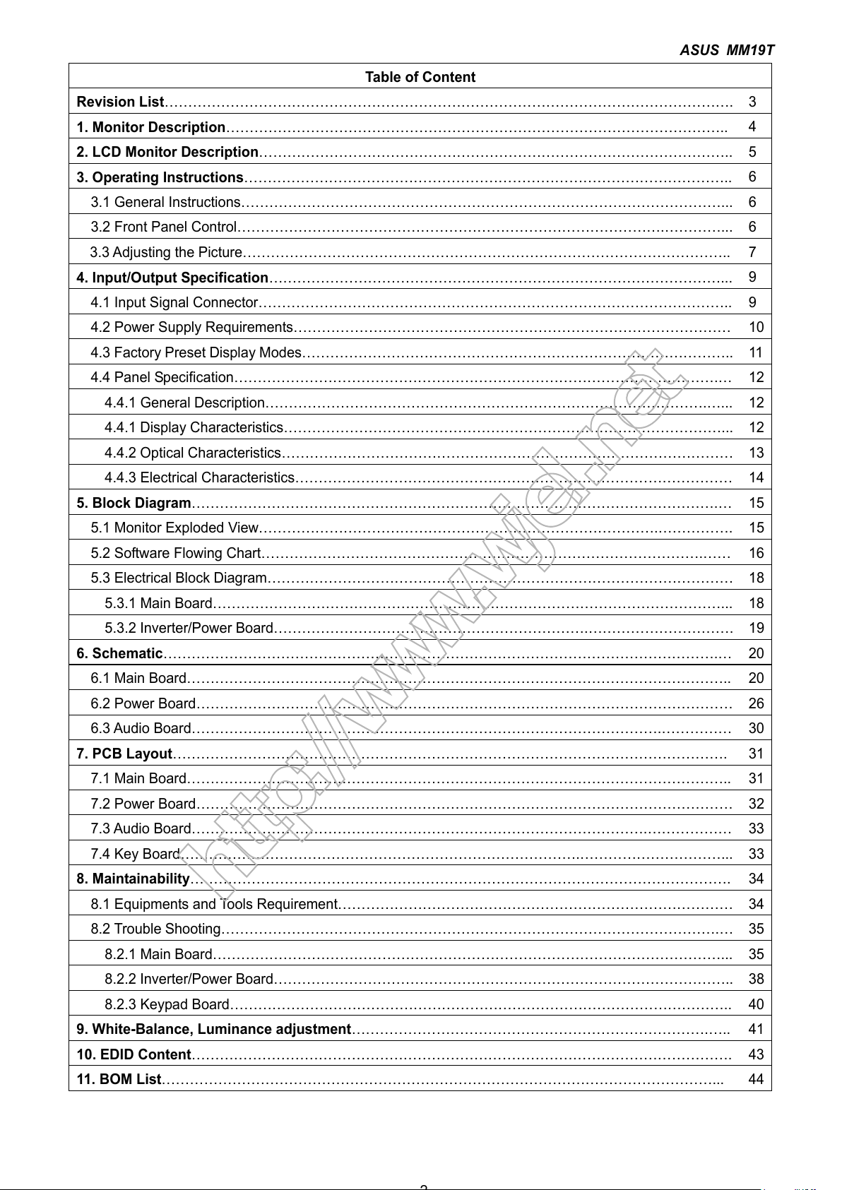
Table of Content
Revision List………………………………………………………………………………………………………….
3
1. Monitor Description……………………………………………………………………………………………..
4
2. LCD Monitor Description………………………………………………………………………………………..
5
3. Operating Instructions…………………………………………………………………………………………..
6
3.1 General Instructions…………………………………………………………………………………………... 6
3.2 Front Panel Control……………………………………………………………………………….…………... 6
3.3 Adjusting the Picture………………………………………………………………………………………….. 7
4. Input/Output Specification……………………………………………………………………………………...
9
4.1 Input Signal Connector……………………………………………………………………………………….. 9
4.2 Power Supply Requirements………………………………………………………………………………… 10
4.3 Factory Preset Display Modes……………………………………………………………………………….. 11
4.4 Panel Specification………………………………………………………………………………………….… 12
4.4.1 General Description………………………………………………………………………………….…... 12
4.4.1 Display Characteristics…………………………………………………………………………………... 12
4.4.2 Optical Characteristics…………………………………………………………………………………… 13
4.4.3 Electrical Characteristics………………………………………………………………………………… 14
5. Block Diagram………………………………………………………………………………………………….…
15
5.1 Monitor Exploded View………………………………………………………………………….……………. 15
5.2 Software Flowing Chart………………………………………………………………………………….…… 16
5.3 Electrical Block Diagram……………………………………………………………………………………… 18
5.3.1 Main Board………………………………………………………………………………………………... 18
5.3.2 Inverter/Power Board………………………………………………………….…………………………. 19
6. Schematic……………………………………………………………………………………………………….…
20
6.1 Main Board…………………………………………………………………………………………………….. 20
6.2 Power Board…………………………………………………………………………………………………… 26
6.3 Audio Board……………………………………………………………………………………….…………… 30
7. PCB Layout……………………………………………………………………………………………………….
31
7.1 Main Board…………………………………………………………………………………………………….. 31
7.2 Power Board…………………………………………………………………………………………………… 32
7.3 Audio Board…………………………………………………………………………………….……………… 33
7.4 Key Board………………………………………………………………………….…………………………... 33
8. Maintainability…………………………………………………………………………………………………….
34
8.1 Equipments and Tools Requirement………………………………………………………………………… 34
8.2 Trouble Shooting…………………………………………………………………………………………….… 35
8.2.1 Main Board………………………………………………………………………………………………... 35
8.2.2 Inverter/Power Board…………………………………………………………………………………….. 38
8.2.3 Keypad Board…………………………………………………………………………………………….. 40
9. White-Balance, Luminance adjustment………………………………………………………………….…..
41
10. EDID Content…………………………………………………………………………………………………….
43
11. BOM List………………………………………………………………………………………………………...
44
http://www.wjel.net
All manuals and user guides at all-guides.com
ASUS MM19T
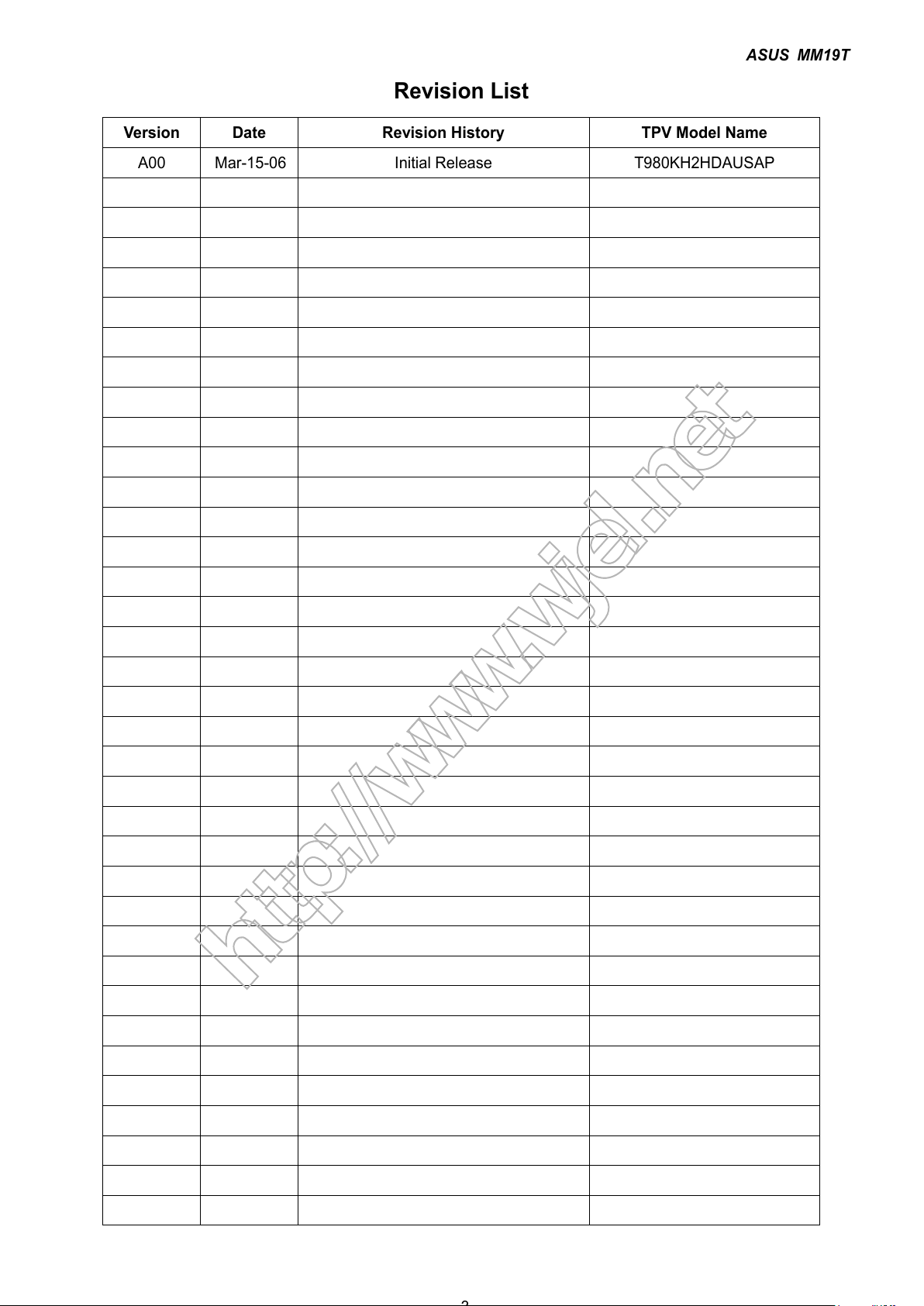
Revision List
Version Date Revision History TPV Model Name
A00 Mar-15-06 Initial Release T980KH2HDAUSAP
http://www.wjel.net
All manuals and user guides at all-guides.com
ASUS MM19T
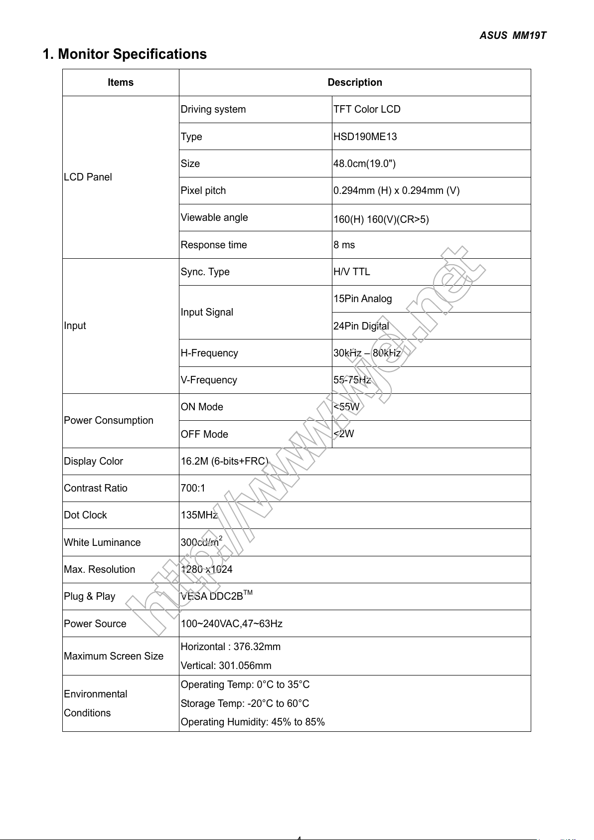
1. Monitor Specifications
Items Description
Driving system TFT Color LCD
Type HSD190ME13
Size 48.0cm(19.0")
Pixel pitch 0.294mm (H) x 0.294mm (V)
Viewable angle
160(H) 160(V)(CR>5)
LCD Panel
Response time 8 ms
Sync. Type H/V TTL
15Pin Analog
Input Signal
24Pin Digital
H-Frequency 30kHz – 80kHz
Input
V-Frequency 55-75Hz
ON Mode <55W
Power Consumption
OFF Mode
<2W
Display Color 16.2M (6-bits+FRC)
Contrast Ratio 700:1
Dot Clock 135MHz
White Luminance 300cd/m
2
Max. Resolution 1280 x1024
Plug & Play VESA DDC2BTM
Power Source 100~240VAC,47~63Hz
Maximum Screen Size
Horizontal : 376.32mm
Vertical: 301.056mm
Environmental
Conditions
Operating Temp: 0°C to 35°C
Storage Temp: -20°C to 60°C
Operating Humidity: 45% to 85%
http://www.wjel.net
All manuals and user guides at all-guides.com
ASUS MM19T
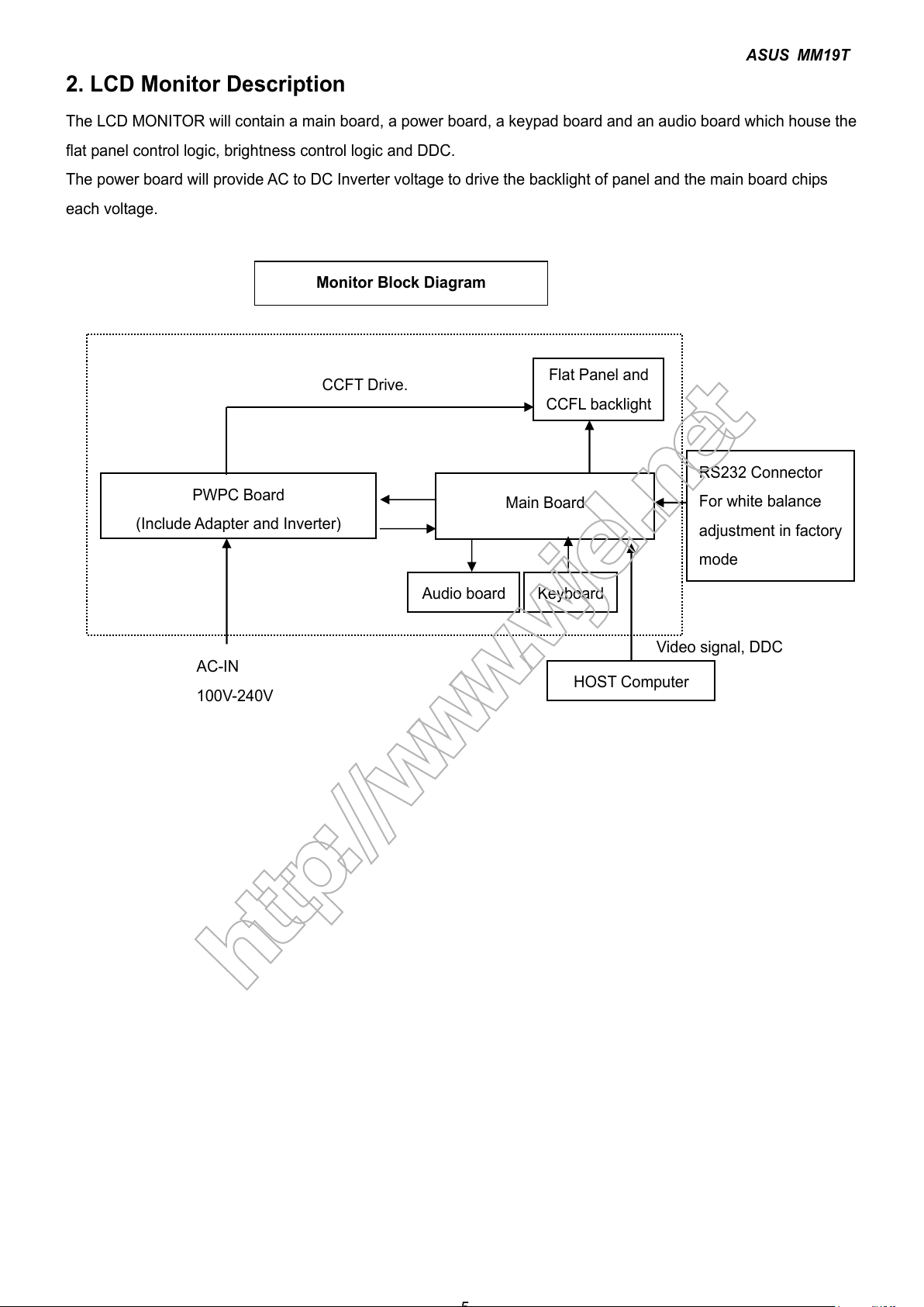
2. LCD Monitor Description
The LCD MONITOR will contain a main board, a power board, a keypad board and an audio board which house the
flat panel control logic, brightness control logic and DDC.
The power board will provide AC to DC Inverter voltage to drive the backlight of panel and the main board chips
each voltage.
Video signal, DDC
CCFT Drive.
PWPC Board
(
Include Adapter and Inverter)
Flat Panel and
CCFL backlight
Main Board
RS232 Connector
For white balance
adjustment in factory
mode
HOST Computer
AC-IN
100V-240V
Monitor Block Diagram
Audio board Keyboard
http://www.wjel.net
All manuals and user guides at all-guides.com
ASUS MM19T
3. Operating Instructions
3.1 General Instructions
Press the power button to turn the monitor on or off. The other control buttons are located in front panel of the
monitor. By changing these settings, the picture can be adjusted to your personal preferences.
• The power cord should be connected.
• Connect the video cable from the monitor to the video card.
• Press the power button to turn on the monitor position. The power indicator will light up.
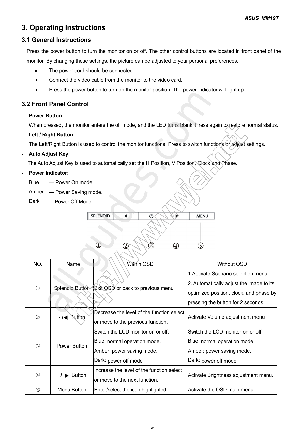
3.2 Front Panel Control
- Power Button:
When pressed, the monitor enters the off mode, and the LED turns blank. Press again to restore normal status.
- Left / Right Button:
The Left/Right Button is used to control the monitor functions. Press to switch functions or adjust settings.
- Auto Adjust Key:
The Auto Adjust Key is used to automatically set the H Position, V Position, Clock and Phase.
- Power Indicator:
Blue — Power On mode.
Amber
— Power Saving mode.
Dark
—Power Off Mode.
NO. Name
Within OSD
Without OSD
①
Splendid Button Exit OSD or back to previous menu
1.Activate Scenario selection menu.
2. Automatically adjust the image to its
optimized position, clock, and phase by
pressing the button for 2 seconds.
② - /
Button
Decrease the level of the function select
or move to the previous function.
Activate Volume adjustment menu
③
Power Button
Switch the LCD monitor on or off.
Blue:
normal operation mode
.
Amber: power saving mode.
Dark:
power off mode
Switch the LCD monitor on or off.
Blue:
normal operation mode
.
Amber: power saving mode.
Dark:
power off mode
④ +/ Button
Increase the level of the function select
or move to the next function.
Activate Brightness adjustment menu.
⑤
Menu Button Enter/select the icon highlighted . Activate the OSD main menu.
http://www.wjel.net
All manuals and user guides at all-guides.com
all-guides.com
ASUS MM19T
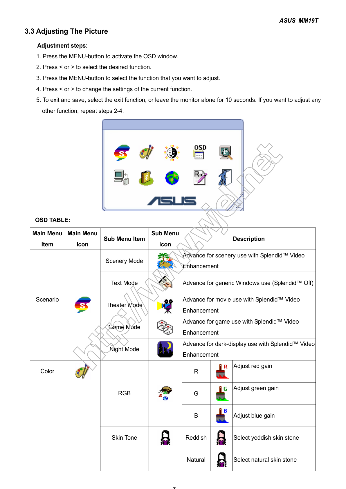
3.3 Adjusting The Picture
Adjustment steps:
1. Press the MENU-button to activate the OSD window.
2. Press < or > to select the desired function.
3. Press the MENU-button to select the function that you want to adjust.
4. Press < or > to change the settings of the current function.
5. To exit and save, select the exit function, or leave the monitor alone for 10 seconds. If you want to adjust any
other function, repeat steps 2-4.
OSD TABLE:
Main Menu
Item
Main Menu
Icon
Sub Menu Item
Sub Menu
Icon
Description
Scenery Mode
Advance for scenery use with Splendid™ Video
Enhancement
Text Mode
Advance for generic Windows use (Splendid™ Off)
Theater Mode
Advance for movie use with Splendid™ Video
Enhancement
Game Mode
Advance for game use with Splendid™ Video
Enhancement
Scenario
Night Mode
Advance for dark-display use with Splendid™ Video
Enhancement
R
Adjust red gain
G
Adjust green gain
RGB
B
Adjust blue gain
Reddish Select yeddish skin stone
Color
Skin Tone
Natural
Select natural skin stone
http://www.wjel.net
All manuals and user guides at all-guides.com
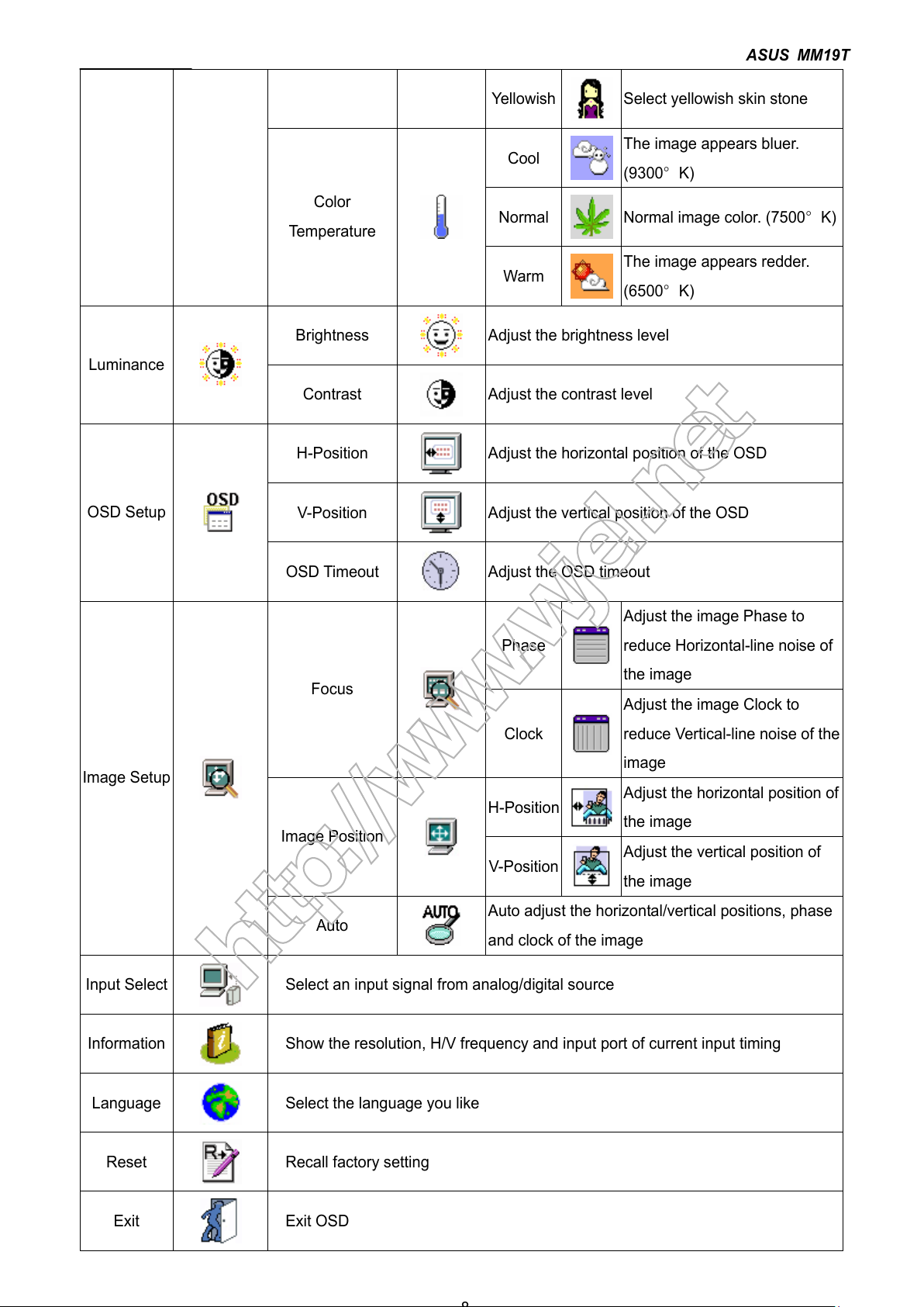
ASUS MM19T
Yellowish
Select yellowish skin stone
Cool
The image appears bluer.
(9300°K)
Normal
Normal image color. (7500°K)
Color
Temperature
Warm
The image appears redder.
(6500°K)
Brightness
Adjust the brightness level
Luminance
Contrast
Adjust the contrast level
H-Position
Adjust the horizontal position of the OSD
V-Position
Adjust the vertical position of the OSD
OSD Setup
OSD Timeout
Adjust the OSD timeout
Phase
Adjust the image Phase to
reduce Horizontal-line noise of
the image
Focus
Clock
Adjust the image Clock to
reduce Vertical-line noise of the
image
H-Position
Adjust the horizontal position of
the image
Image Position
V-Position
Adjust the vertical position of
the image
Image Setup
Auto
Auto adjust the horizontal/vertical positions, phase
and clock of the image
Input Select
Select an input signal from analog/digital source
Information
Show the resolution, H/V frequency and input port of current input timing
Language
Select the language you like
Reset
Recall factory setting
Exit
Exit OSD
http://www.wjel.net
All manuals and user guides at all-guides.com
ASUS MM19T
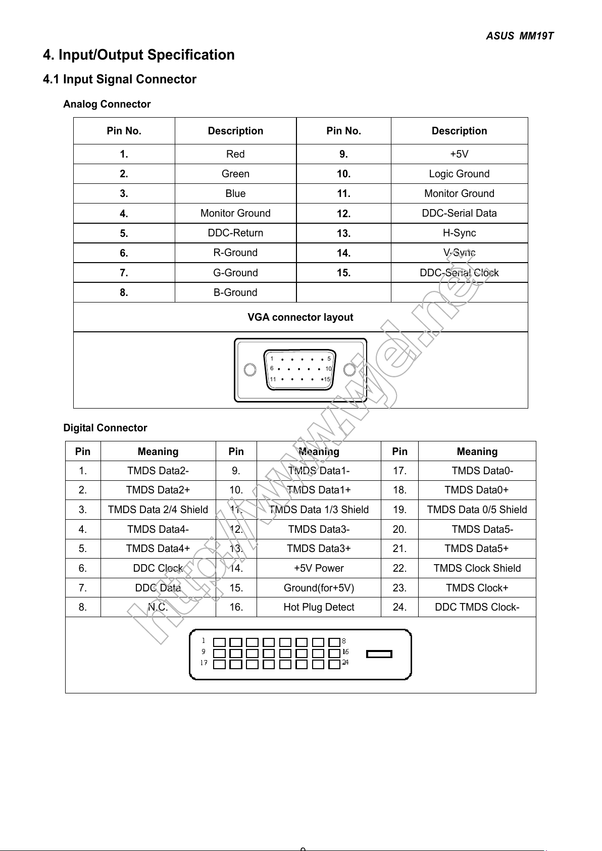
4. Input/Output Specification
4.1 Input Signal Connector
Analog Connector
Pin No. Description Pin No. Description
1.
Red
9.
+5V
2.
Green
10.
Logic Ground
3.
Blue
11.
Monitor Ground
4.
Monitor Ground
12.
DDC-Serial Data
5.
DDC-Return
13.
H-Sync
6.
R-Ground
14.
V-Syn c
7.
G-Ground
15.
DDC-Serial Clock
8.
B-Ground
VGA connector layout
15
6
10
11 15
Digital Connector
Pin Meaning Pin Meaning Pin Meaning
1. TMDS Data2- 9. TMDS Data1- 17. TMDS Data0-
2. TMDS Data2+ 10. TMDS Data1+ 18. TMDS Data0+
3. TMDS Data 2/4 Shield 11. TMDS Data 1/3 Shield 19. TMDS Data 0/5 Shield
4. TMDS Data4- 12. TMDS Data3- 20. TMDS Data5-
5. TMDS Data4+ 13. TMDS Data3+ 21. TMDS Data5+
6. DDC Clock 14. +5V Power 22. TMDS Clock Shield
7. DDC Data 15. Ground(for+5V) 23. TMDS Clock+
8. N.C. 16. Hot Plug Detect 24. DDC TMDS Clock-
http://www.wjel.net
All manuals and user guides at all-guides.com
ASUS MM19T
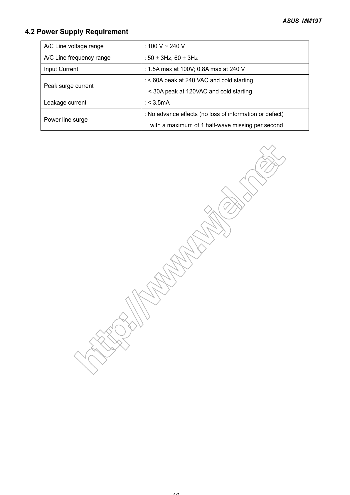
4.2 Power Supply Requirement
A/C Line voltage range : 100 V ~ 240 V
A/C Line frequency range
: 50 ± 3Hz, 60 ± 3Hz
Input Current : 1.5A max at 100V; 0.8A max at 240 V
Peak surge current
: < 60A peak at 240 VAC and cold starting
< 30A peak at 120VAC and cold starting
Leakage current : < 3.5mA
Power line surge
: No advance effects (no loss of information or defect)
with a maximum of 1 half-wave missing per second
http://www.wjel.net
All manuals and user guides at all-guides.com
ASUS MM19T
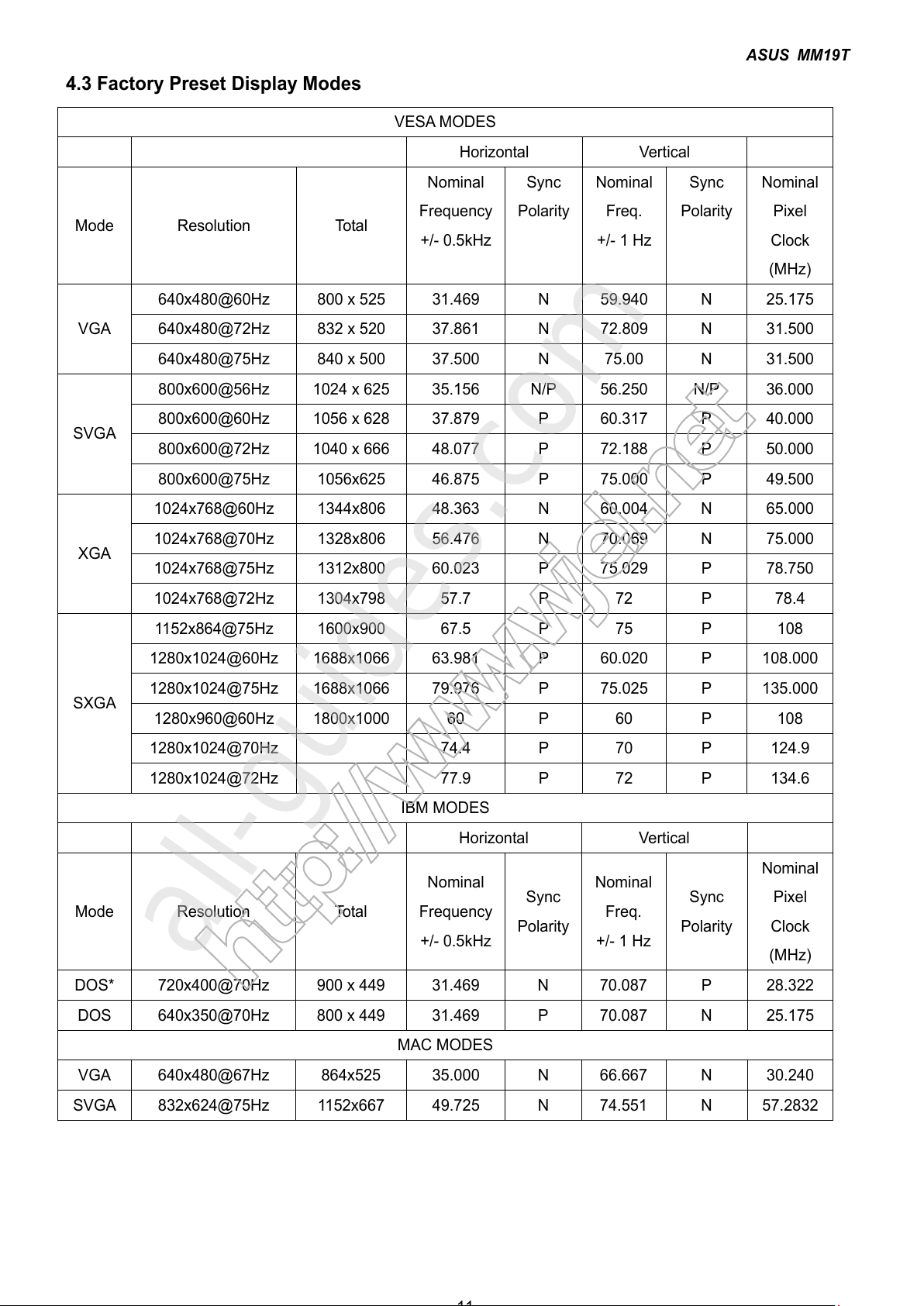
4.3 Factory Preset Display Modes
VESA MODES
Horizontal Vertical
Mode Resolution Total
Nominal
Frequency
+/- 0.5kHz
Sync
Polarity
Nominal
Freq.
+/- 1 Hz
Sync
Polarity
Nominal
Pixel
Clock
(MHz)
640x480@60Hz 800 x 525 31.469 N 59.940 N 25.175
640x480@72Hz 832 x 520 37.861 N 72.809 N 31.500
VGA
640x480@75Hz 840 x 500 37.500 N 75.00 N 31.500
800x600@56Hz 1024 x 625 35.156 N/P 56.250 N/P 36.000
800x600@60Hz 1056 x 628 37.879 P 60.317 P 40.000
800x600@72Hz 1040 x 666 48.077 P 72.188 P 50.000
SVGA
800x600@75Hz 1056x625 46.875 P 75.000 P 49.500
1024x768@60Hz 1344x806 48.363 N 60.004 N 65.000
1024x768@70Hz 1328x806 56.476 N 70.069 N 75.000
1024x768@75Hz 1312x800 60.023 P 75.029 P 78.750
XGA
1024x768@72Hz 1304x798 57.7 P 72 P 78.4
1152x864@75Hz 1600x900 67.5 P 75 P 108
1280x1024@60Hz 1688x1066 63.981 P 60.020 P 108.000
1280x1024@75Hz 1688x1066 79.976 P 75.025 P 135.000
1280x960@60Hz 1800x1000 60 P 60 P 108
1280x1024@70Hz 74.4 P 70 P 124.9
SXGA
1280x1024@72Hz 77.9 P 72 P 134.6
IBM MODES
Horizontal Vertical
Mode Resolution Total
Nominal
Frequency
+/- 0.5kHz
Sync
Polarity
Nominal
Freq.
+/- 1 Hz
Sync
Polarity
Nominal
Pixel
Clock
(MHz)
DOS* 720x400@70Hz 900 x 449 31.469 N 70.087 P 28.322
DOS 640x350@70Hz 800 x 449 31.469 P 70.087 N 25.175
MAC MODES
VGA 640x480@67Hz 864x525 35.000 N 66.667 N 30.240
SVGA 832x624@75Hz 1152x667 49.725 N 74.551 N 57.2832
http://www.wjel.net
All manuals and user guides at all-guides.com
all-guides.com
ASUS MM19T
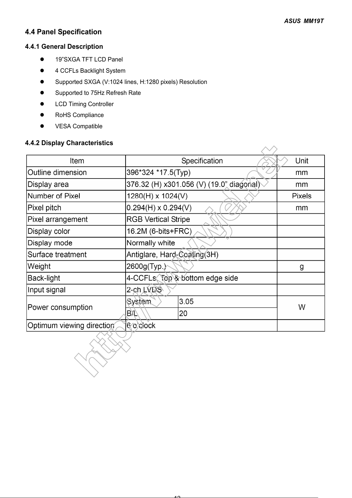
4.4 Panel Specification
4.4.1 General Description
z 19”SXGA TFT LCD Panel
z 4 CCFLs Backlight System
z Supported SXGA (V:1024 lines, H:1280 pixels) Resolution
z Supported to 75Hz Refresh Rate
z LCD Timing Controller
z RoHS Compliance
z VESA Compatible
4.4.2 Display Characteristics
http://www.wjel.net
All manuals and user guides at all-guides.com
ASUS MM19T
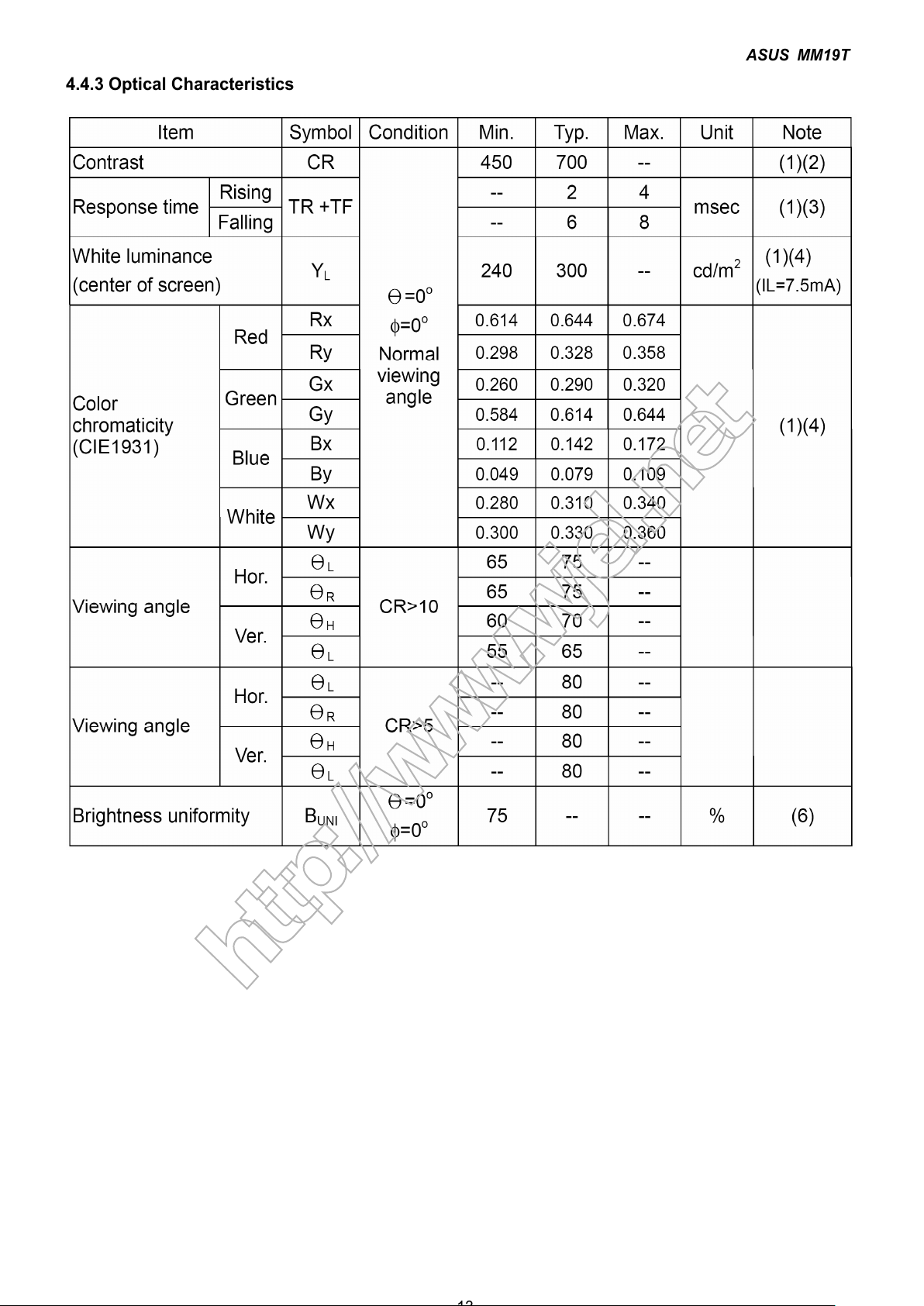
4.4.3 Optical Characteristics
http://www.wjel.net
All manuals and user guides at all-guides.com
ASUS MM19T
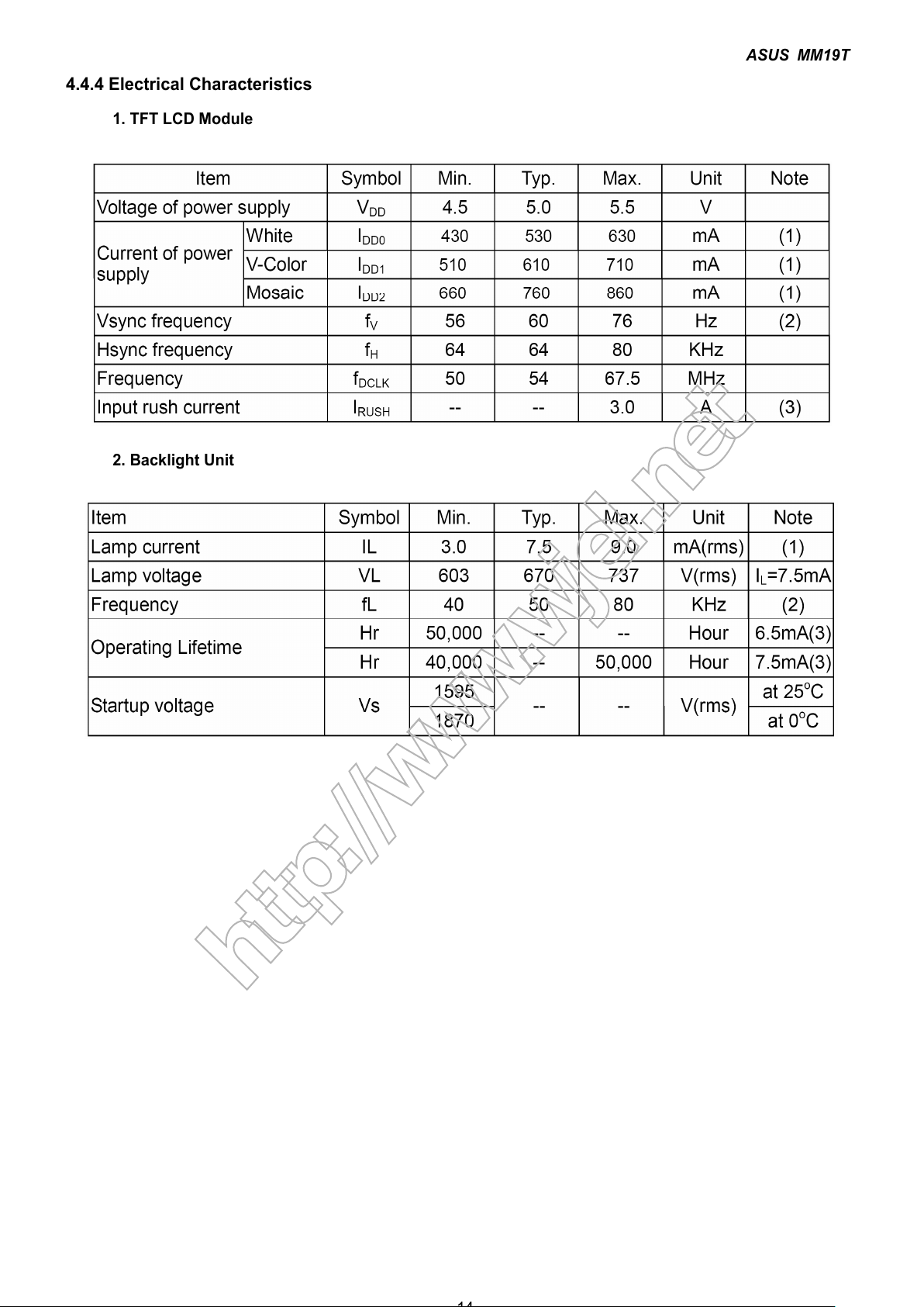
4.4.4 Electrical Characteristics
1. TFT LCD Module
2. Backlight Unit
http://www.wjel.net
All manuals and user guides at all-guides.com
ASUS MM19T
15
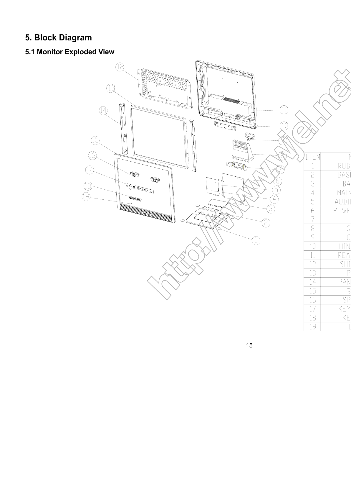
5. Block Diagram
5.1 Monitor Exploded View
http://www.wjel.net
All manuals and user guides at all-guides.com
ASUS MM19T
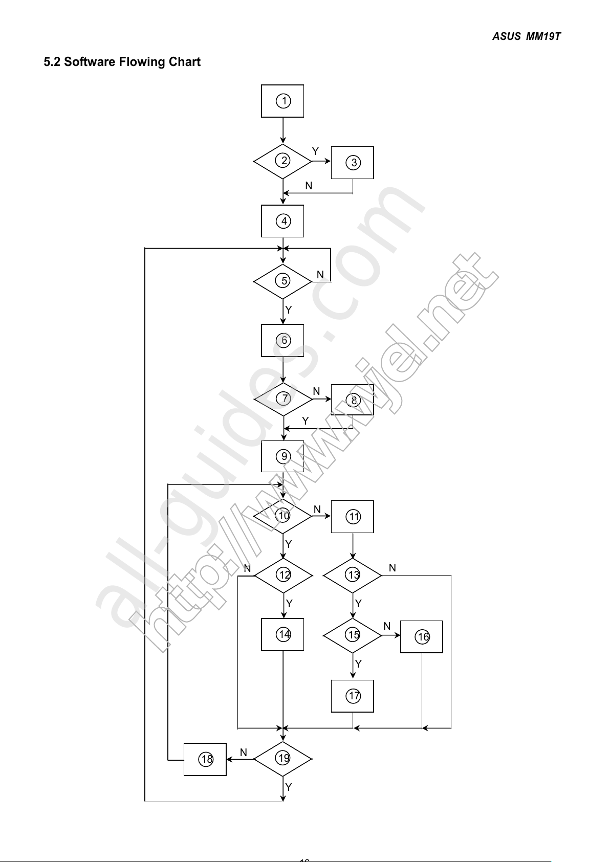
5.2 Software Flowing Chart
1
2
N
Y
5
Y
N
10
Y
N
12
Y
N
7
Y
N
6
4
3
8
9
14
11
13
Y
N
15
Y
N
16
17
19
Y
N
18
http://www.wjel.net
All manuals and user guides at all-guides.com
all-guides.com
ASUS MM19T
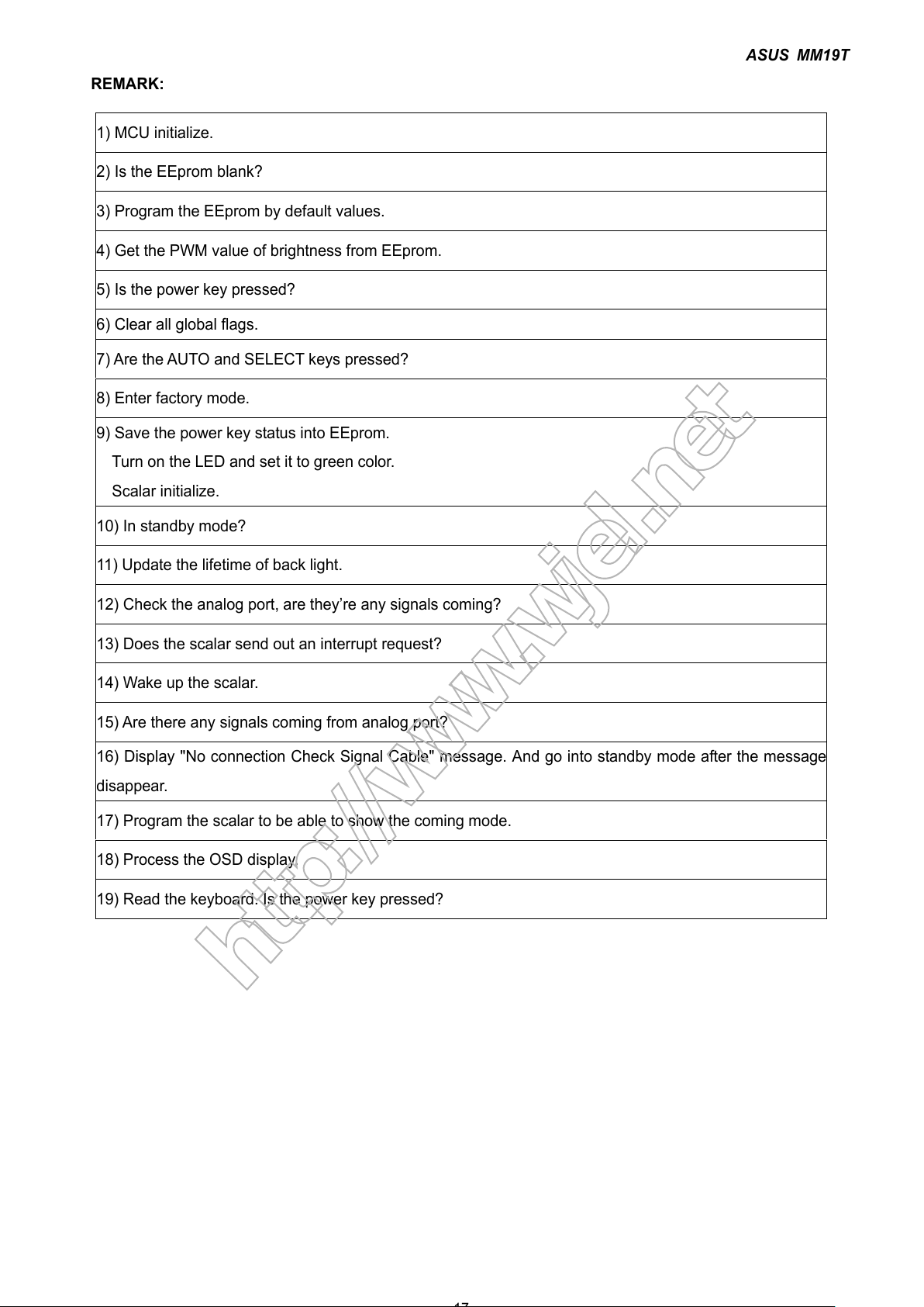
REMARK:
1) MCU initialize.
2) Is the EEprom blank?
3) Program the EEprom by default values.
4) Get the PWM value of brightness from EEprom.
5) Is the power key pressed?
6) Clear all global flags.
7) Are the AUTO and SELECT keys pressed?
8) Enter factory mode.
9) Save the power key status into EEprom.
Turn on the LED and set it to green color.
Scalar initialize.
10) In standby mode?
11) Update the lifetime of back light.
12) Check the analog port, are they’re any signals coming?
13) Does the scalar send out an interrupt request?
14) Wake up the scalar.
15) Are there any signals coming from analog port?
16) Display "No connection Check Signal Cable" message. And go into standby mode after the message
disappear.
17) Program the scalar to be able to show the coming mode.
18) Process the OSD display.
19) Read the keyboard. Is the power key pressed?
http://www.wjel.net
All manuals and user guides at all-guides.com
ASUS MM19T
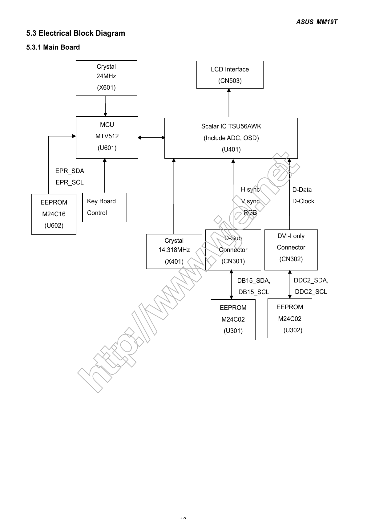
5.3 Electrical Block Diagram
5.3.1 Main Board
MCU
MTV512
(U601)
Scalar IC TSU56AWK
(Include ADC, OSD)
(U401)
EEPROM
M24C16
(U602)
D-Sub
Connector
(CN301)
EEPROM
M24C02
(U301)
H sync
V sync
RGB
DB15_SDA,
DB15
_
SCL
EPR_SDA
EPR_SCL
LCD Interface
(CN503)
EEPROM
M24C02
(U302)
DDC2_SDA,
DDC2_SCL
D-Data
D-Clock
Key Board
Control
Crystal
24MHz
(X601)
Crystal
14.318MHz
(X401)
DVI-I only
Connector
(CN302)
http://www.wjel.net
All manuals and user guides at all-guides.com
 Loading...