How it Works
Log In / Sign Up
Buy Points
How it Works
FAQ
Contact Us
Questions and Suggestions
Users
Asus
Loading...
M
M51VR
10
M51VR-AP036C
M51VR-AP114C
M51VR-AS039C
M5200
M5200-AS-D792
M52AD
4
M52BC
5
M52BC-CZ005T
M52V
11
M52V (G60VX)
M530W
20
M533
32
M533IA-BQ023T
M533IA-BQ278T
M570DD-DM001
M570DD-DM001T
M570DD-DM052
M570DD-DM057
M570DD-DM179T
M570DD-E4003T
M570DD-E4065
M580GD
30
M580VD
30
M5A
9
M5A78L
6
M5A78L LE
5
M5A78L LE R2.0
M5A78L-M
2
M5A78L-M LE
5
M5A78L-M LE/USB3
2
M5A78L-M LX
6
M5A78L-M LX3
8
M5A78L-M LX3 PLUS
5
M5A78L-M LX/BR
M5A78L-M LX PLUS
4
M5A78L-M LX V2
4
M5A78L-M PLUS
6
M5A78L-M PLUS/USB3
3
M5A78L-M-USB3
6
M5A78L USB3
4
M5A87
7
M5A88-M
7
M5A88-M EVO
3
M5A88-V
M5A88-V EVO
7
M5A97
11
M5A97 EVO
9
M5A97 EVO R2.0
6
M5A97 LE
2
M5A97LER20
8
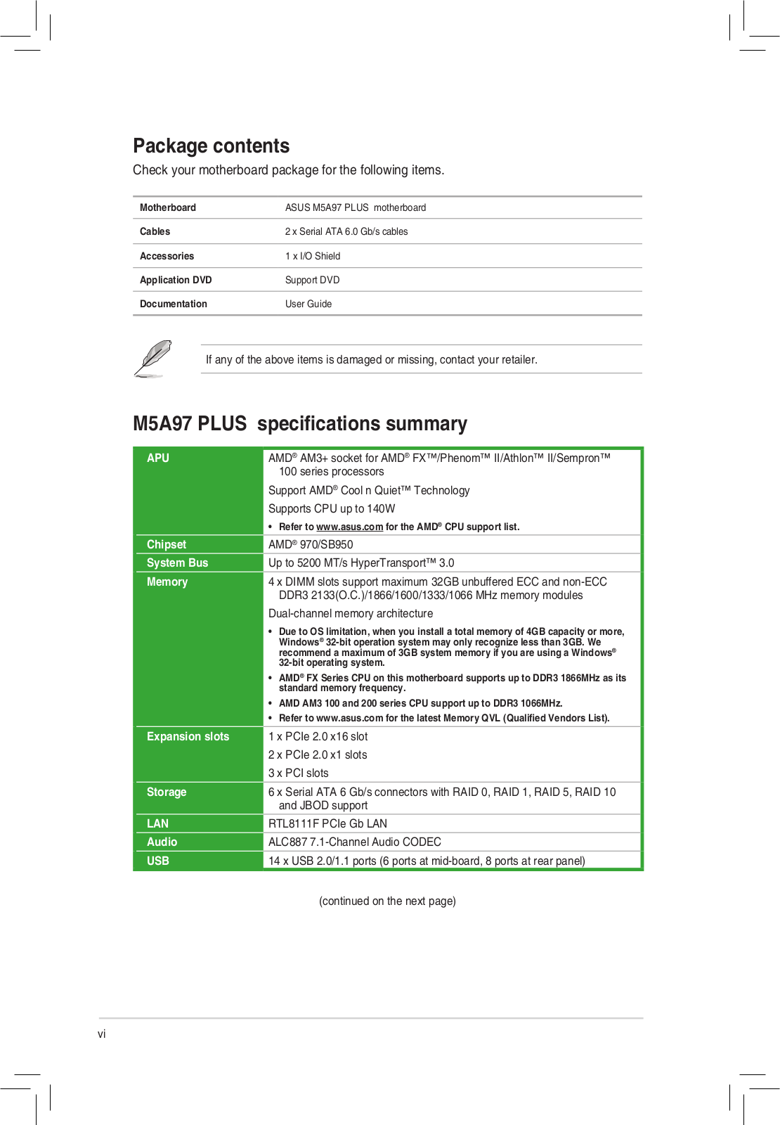
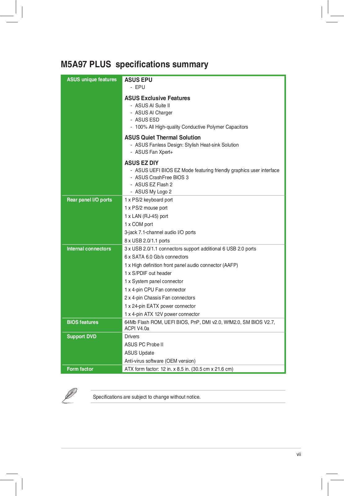
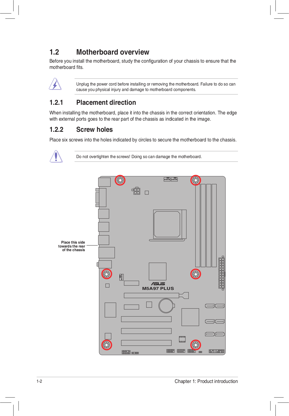
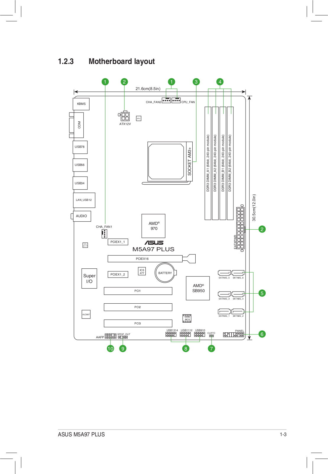
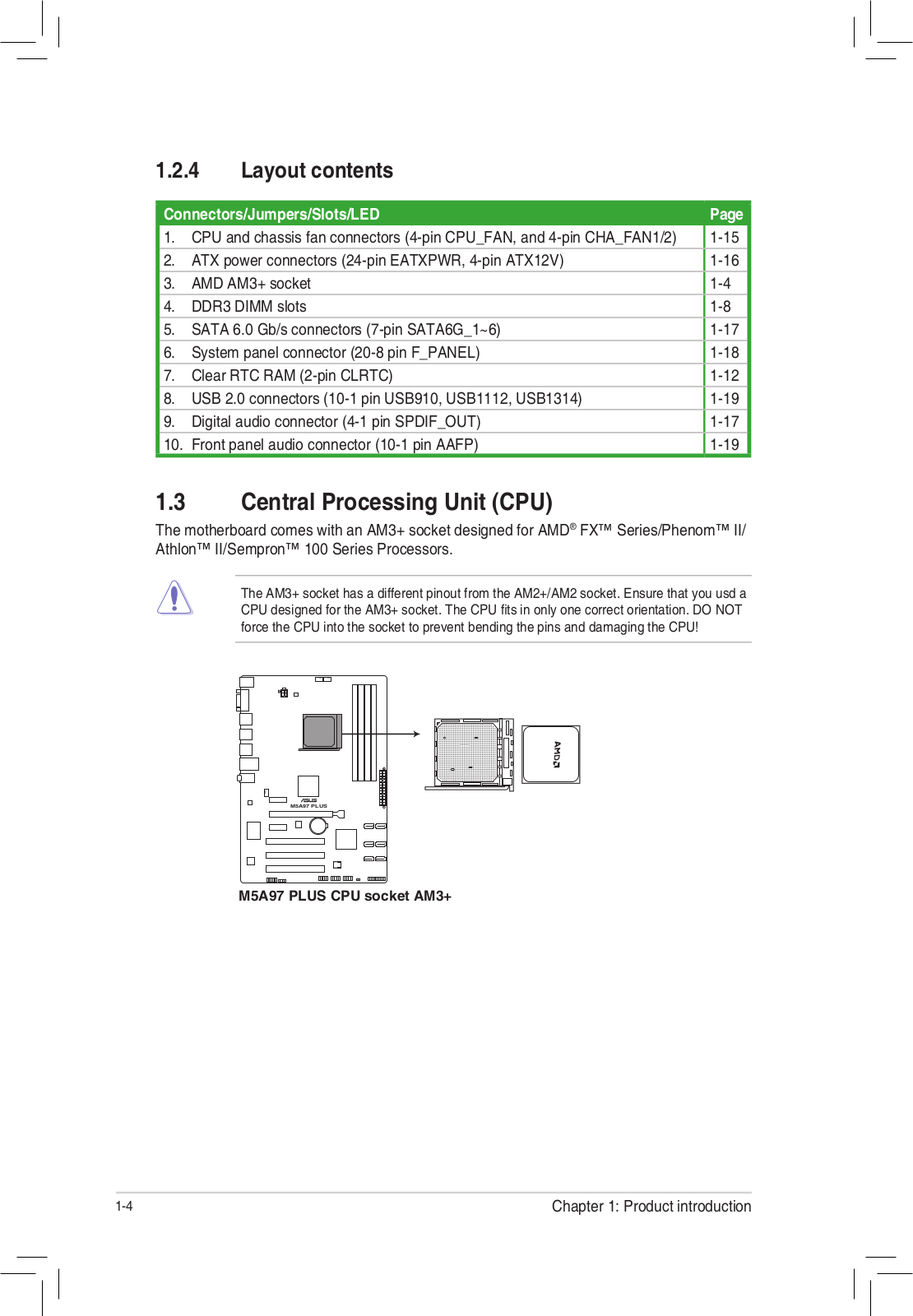
M5A97 PLUS
3
M5A97 PRO
8
M5A97 R2.0
6
M5A97-SI
M5A99FX PRO
M5A99FX PRO R2.0
7
M5A99FX R2.0
M5A99X
2
M5A99X EVO
9
M5A99X EVO R2.0
7
M5AE
8
M5AE-6001P
M5AE-6014P
M5N
7
M5NP
9
M5NP16E
M6
2
m6000
2
M60J
22
M60J-A1
M60VP
4
M6A
5
M6N
5
M6NA
2
M6NE
M6NE16
M6NE17
M6NE20
M6N INSTANT FUN
M6R
3
M6RF
2
M6V
6
M6VA
4
M6Va-Q022H
M6VA-S001P-A
M6VA-S026P
M70
M700KL
3
M705BA-BX067T
M70AD
48
M70SA
3
M70SA-7U011C
M70SA-C1
M70SA-X2
M70SR
15
M70SR-7S010C
M70SR-7U011C
M70Sv
M70T
Loading...
Loading...
Nothing found
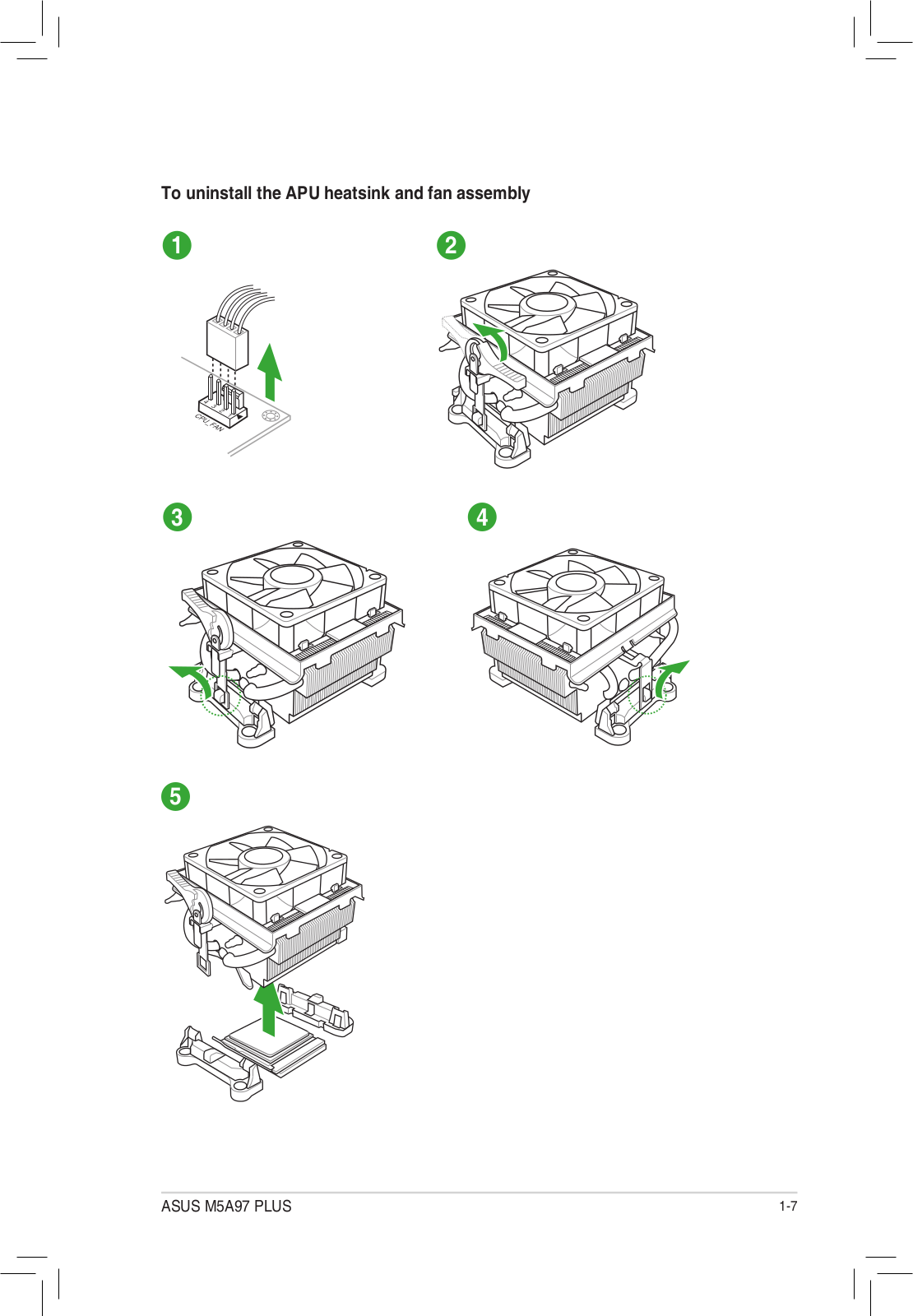
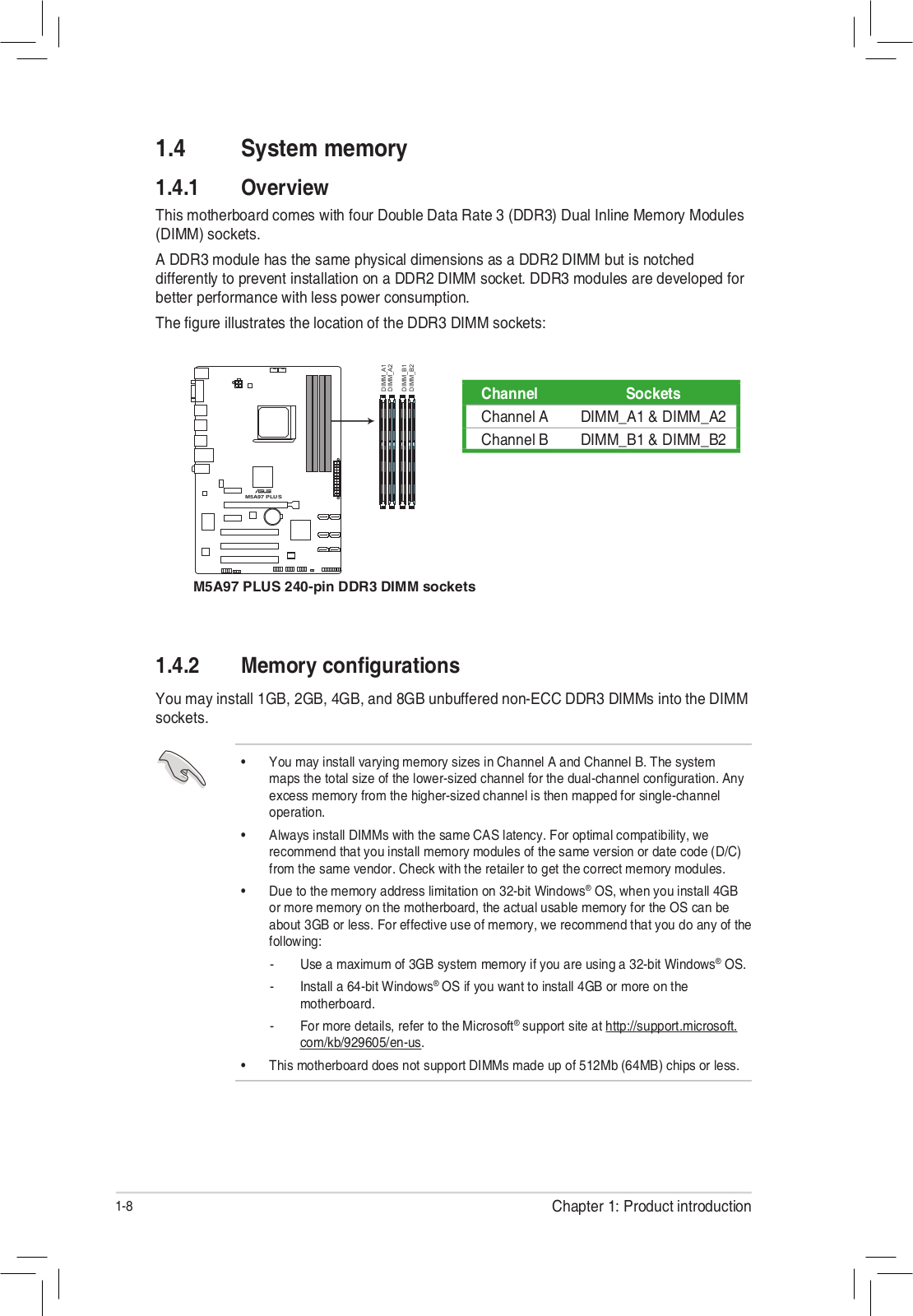
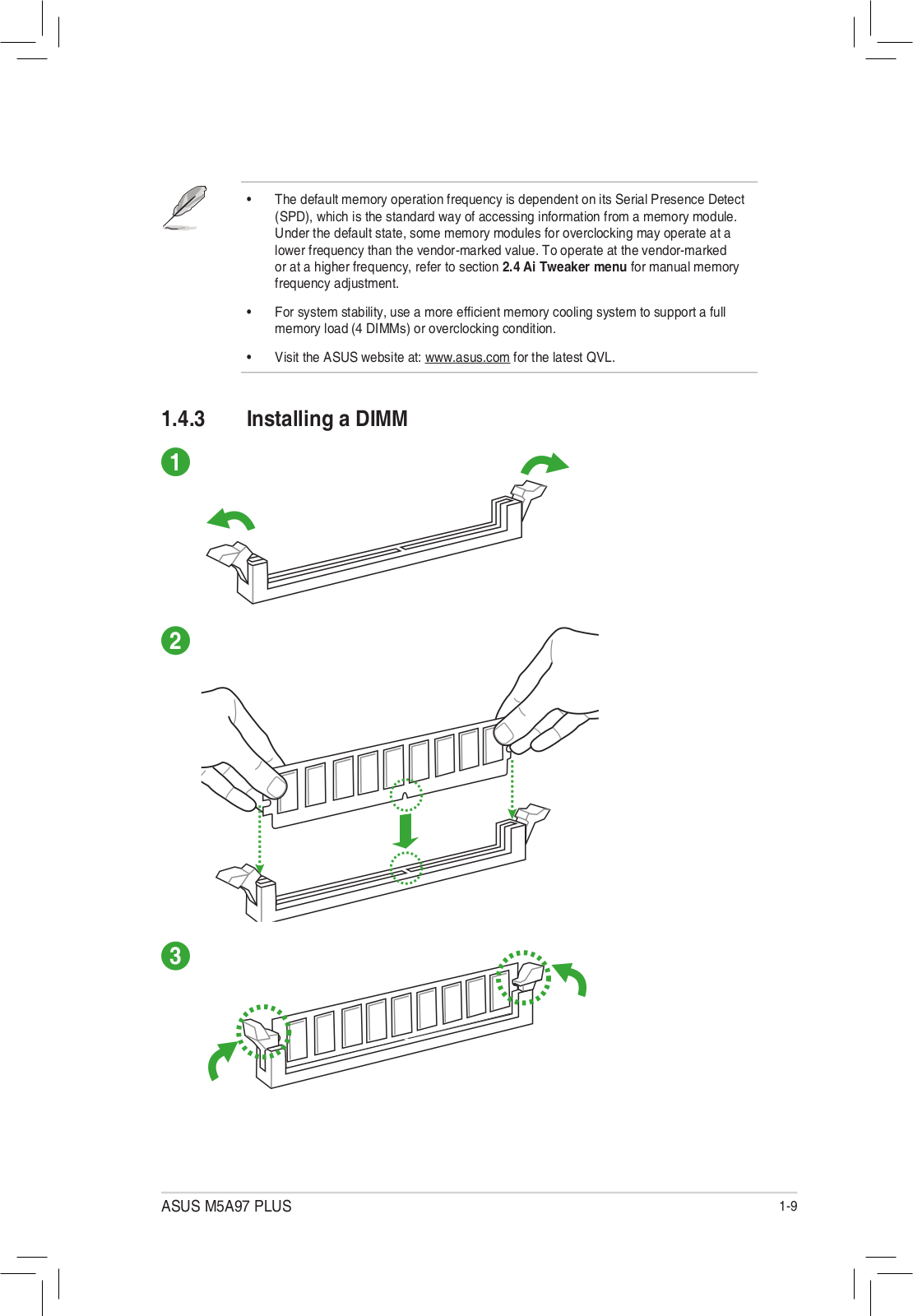
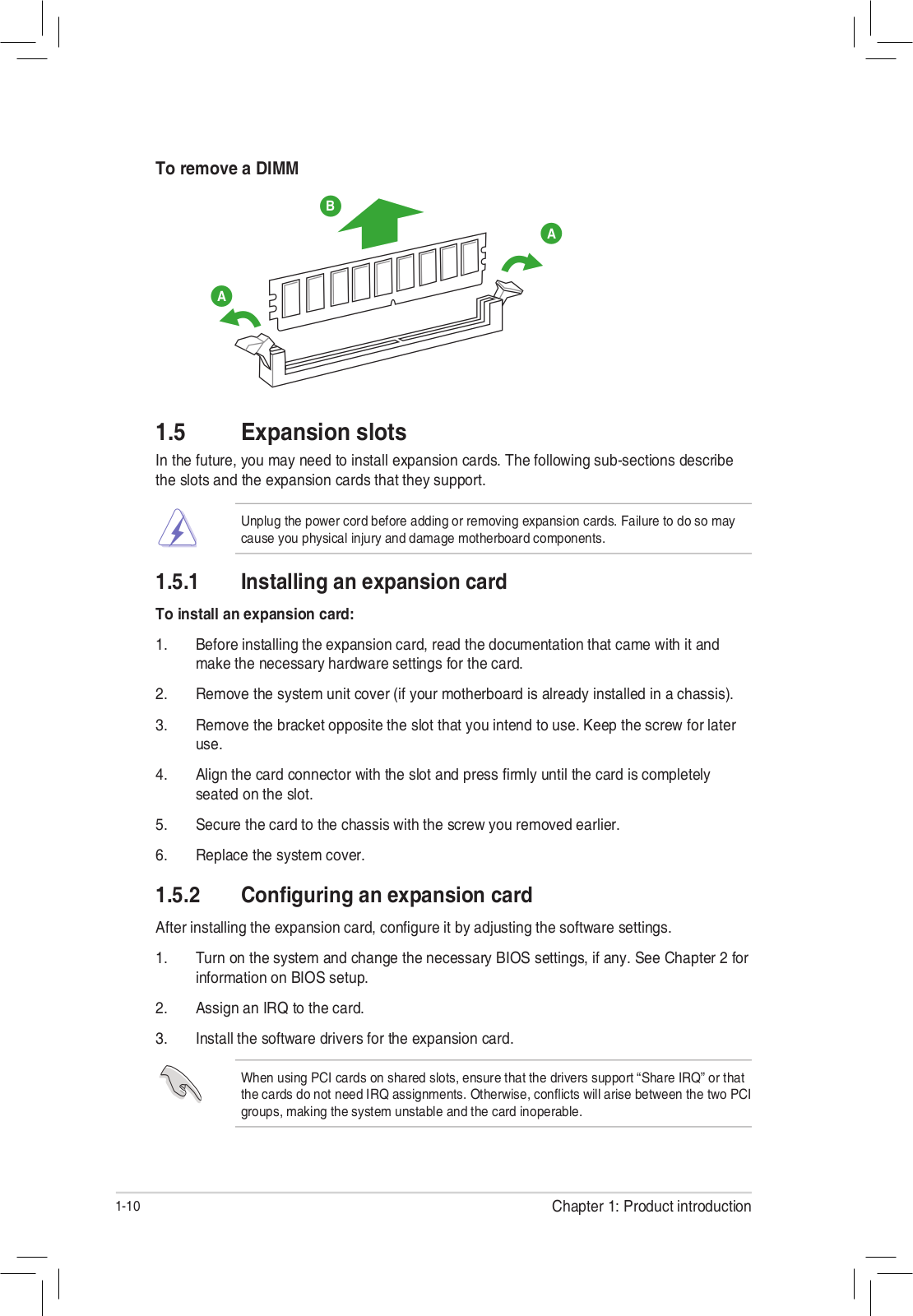
M5A97 PLUS
Quick Start Guide
2 pgs
1.56 Mb
0
User’s Manual
66 pgs
3.82 Mb
0
User’s Manual [zh]
66 pgs
4.5 Mb
0
Table of contents
Loading...
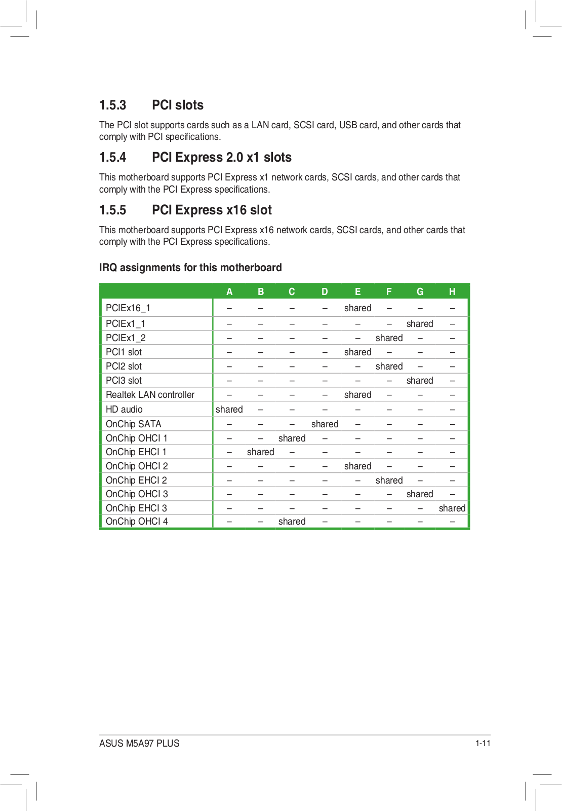
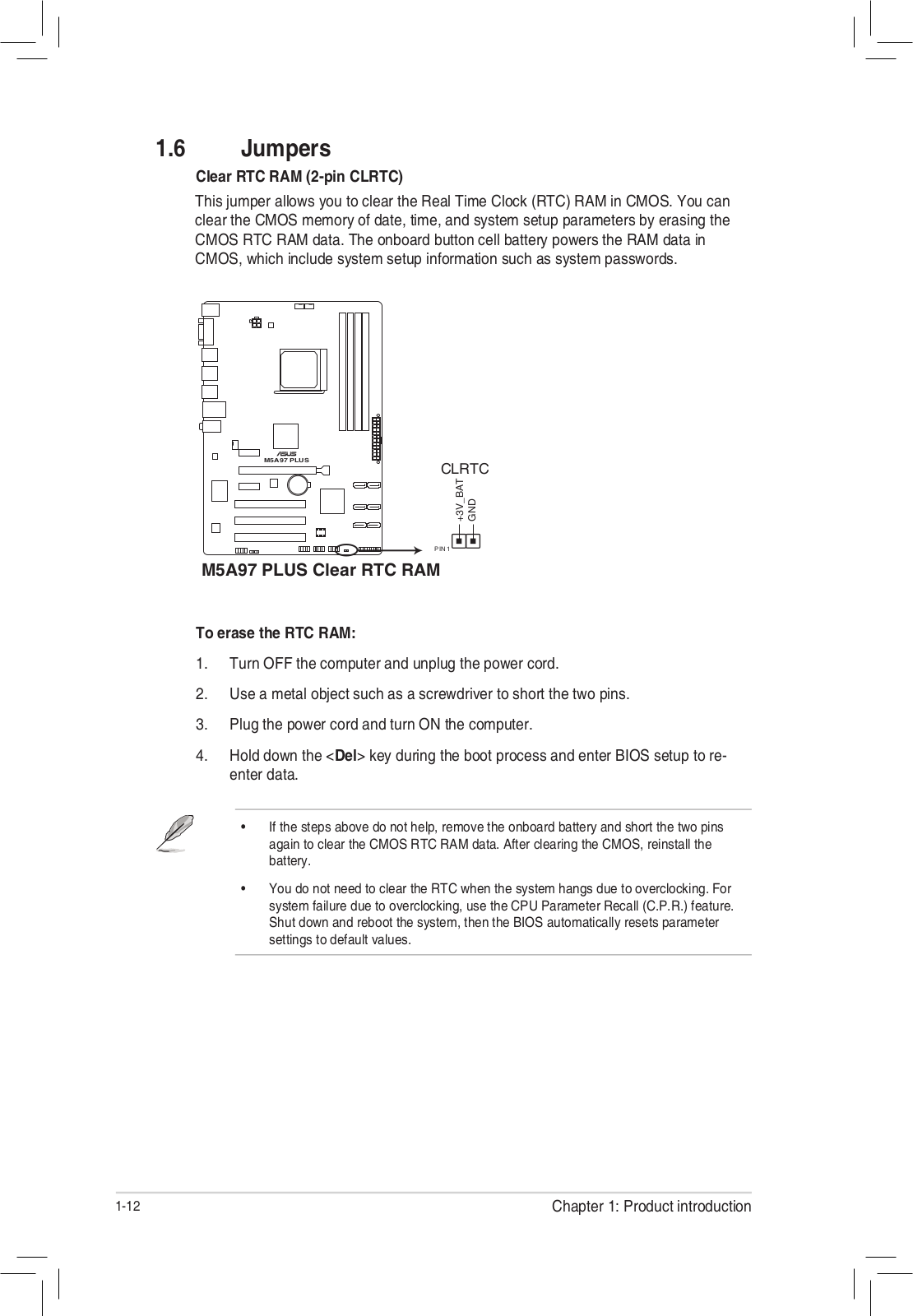
Asus M5A97 PLUS User’s Manual
...
Asus User’s Manual
Download
Specifications and Main Features
Frequently Asked Questions
User Manual
Download
Loading...
+
46
hidden pages
Unhide
You need points to download manuals.
1 point = 1 manual.
You can buy points or you can get point for every manual you upload.
Buy points
Upload your manuals
 Loading...