

ASUS M530W Service Manual
華華碩碩電電腦腦
TSD ■ Lv3Lv4 Repair Manual
ASUS M530w Level 3 &
Level 4 Service Manual
ASUS Proprietary 1

華華碩碩電電腦腦
TSD ■ Lv3Lv4 Repair Manual
Index
1. APPEARANCE ...............................................................................6
1.1 BOX APPEARANCE..................................................................................6
1.2 MAIN COMPONENT NAME & LOCATION........................................ 7
2. BLOCK DIAGRAM........................................................................10
3. HARDWARE EQUIPMENT...........................................................11
3.1 Digital multimeter ...................................................................................11
3.2 Oscilloscope.............................................................................................11
3.3 USB Download Cable .............................................................................11
3.4 Earpiece................................................................................................... 11
3.5 PC ............................................................................................................11
4. DOWNLOAD PROCEDURE............................................................ 12
4.1 Introduction .............................................................................................12
4.2 Operation procedure................................................................................12
4.3 Repair method ......................................................................................... 13
5. LCM DISPLAY .................................................................................14
5.1 Introduction .............................................................................................14
5.2 Measure method ......................................................................................15
5.3 Repair method ......................................................................................... 15
6. USB/CHARGING..............................................................................16
6.1 Introduction .............................................................................................16
6.2 Repair method ......................................................................................... 16
7. KEYPAD........................................................................................... 17
7.1 Introduction .............................................................................................17
7.2 Measure method ......................................................................................20
7.3 Repair method ......................................................................................... 20
ASUS Proprietary 2

華華碩碩電電腦腦
TSD ■ Lv3Lv4 Repair Manual
8. KEYPAD LED ..................................................................................22
8.1 Introduction .............................................................................................22
8.2 Measure method ......................................................................................22
8.3 Measure method ......................................................................................23
9. VIBRATOR.......................................................................................24
9.1 Introduction .............................................................................................24
9.2 Measure method ......................................................................................24
9.3 Repair method ......................................................................................... 25
10. ACOUSTICS .................................................................................. 26
10.1 HANDSET................................................................................................26
10.1.1 Introduction ........................................................................................26
10.1.2 Measure method .................................................................................28
10.1.3 Repair method ....................................................................................28
10.2 EARPIECE...............................................................................................30
10.2.1 Introduction ........................................................................................30
10.2.2 Measure method .................................................................................30
10.2.3 Repair method ....................................................................................31
11. CAMERA
..................................................................................32
Introduction ...................................................................................................32
11.1 2M camera.............................................................................................32
11.1.1 Measure method ..............................................................................32
11.1.2 Repair method .................................................................................33
11.2 VGA camera............................................................................................. 33
11.2.1 Measure method .................................................................................34
11.2.2 Repair method ....................................................................................34
12. SIM INTERFACE............................................................................35
12.1 Introduction .............................................................................................35
ASUS Proprietary 3

華華碩碩電電腦腦
TSD ■ Lv3Lv4 Repair Manual
12.2 Measure method ......................................................................................35
12.3 Repair method .........................................................................................35
13. MICRO-SD CARD.......................................................................... 36
13.1 Introduction .............................................................................................36
13.2 Measure method ......................................................................................36
13.3 Repair method .........................................................................................36
14. FLASH LIGHT LED........................................................................37
14.1 Introduction .............................................................................................37
14.2 Measure method ......................................................................................37
14.3 Repair method .........................................................................................38
15. RF REPAIR EQUIPMENT REQUIREMENTS .............................39
15.1 Software requirements............................................................................39
15.2 Hardware requirements.......................................................................... 39
15.3 Instrument requirements........................................................................39
15.4 Test Environments Setup........................................................................ 41
15.4.1 Instrument linking ...........................................................................41
15.4.2 Fixture.............................................................................................. 42
16. RF BLOCK DIAGRAM................................................................... 43
16.1 GSM block diagram.............................................................................43
16.2 WCDMA block diagram......................................................................44
17. RF TX/RX PATH AND TEST POINTS........................................... 45
ASUS Proprietary 4

華華碩碩電電腦腦
TSD ■ Lv3Lv4 Repair Manual
17.1 GSM Tx/Rx path and test points ........................................................45
17.2 WCDMA Tx/Rx path and test points .................................................48
18. PROCEDURES OF REPAIR.......................................................50
18.1 RF repair’s procedure.......................................................................... 50
18.2 Calibration and pretest error codes for debug.................................. 52
19. GENERAL RF DEBUG ..................................................................61
19.1 General GSM Tx debug....................................................................... 61
19.2 General GSM Rx debug....................................................................... 70
19.3 General WCDMA Tx debug................................................................ 77
19.4 General WCDMA Rx debug ...............................................................84
20. APPENDIX...................................................................................88
20.1 GSM/WCDMA wireless test................................................................88
20.2 Bluetooth test ........................................................................................90
20.3 WiFi test.................................................................................................92
ASUS Proprietary 5
華華碩碩電電腦腦
TSD ■ Lv3Lv4 Repair Manual
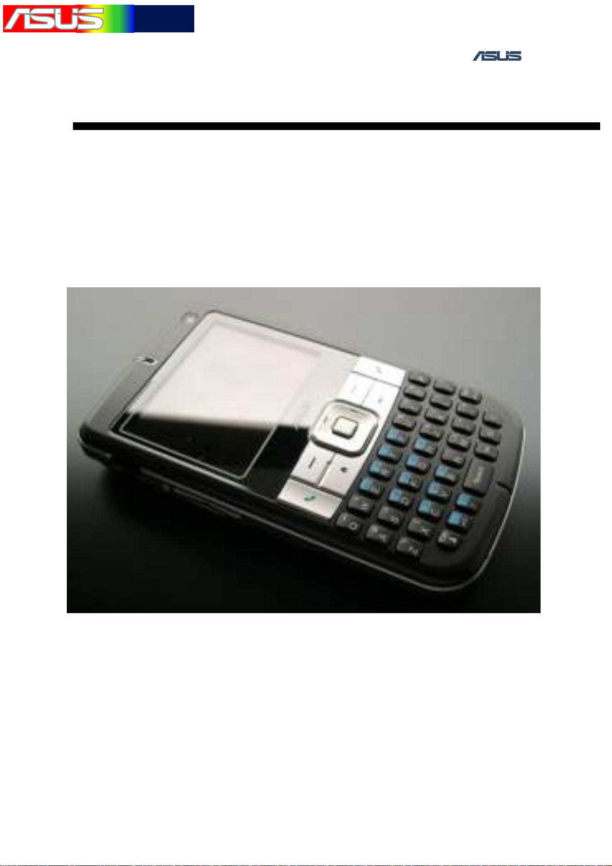
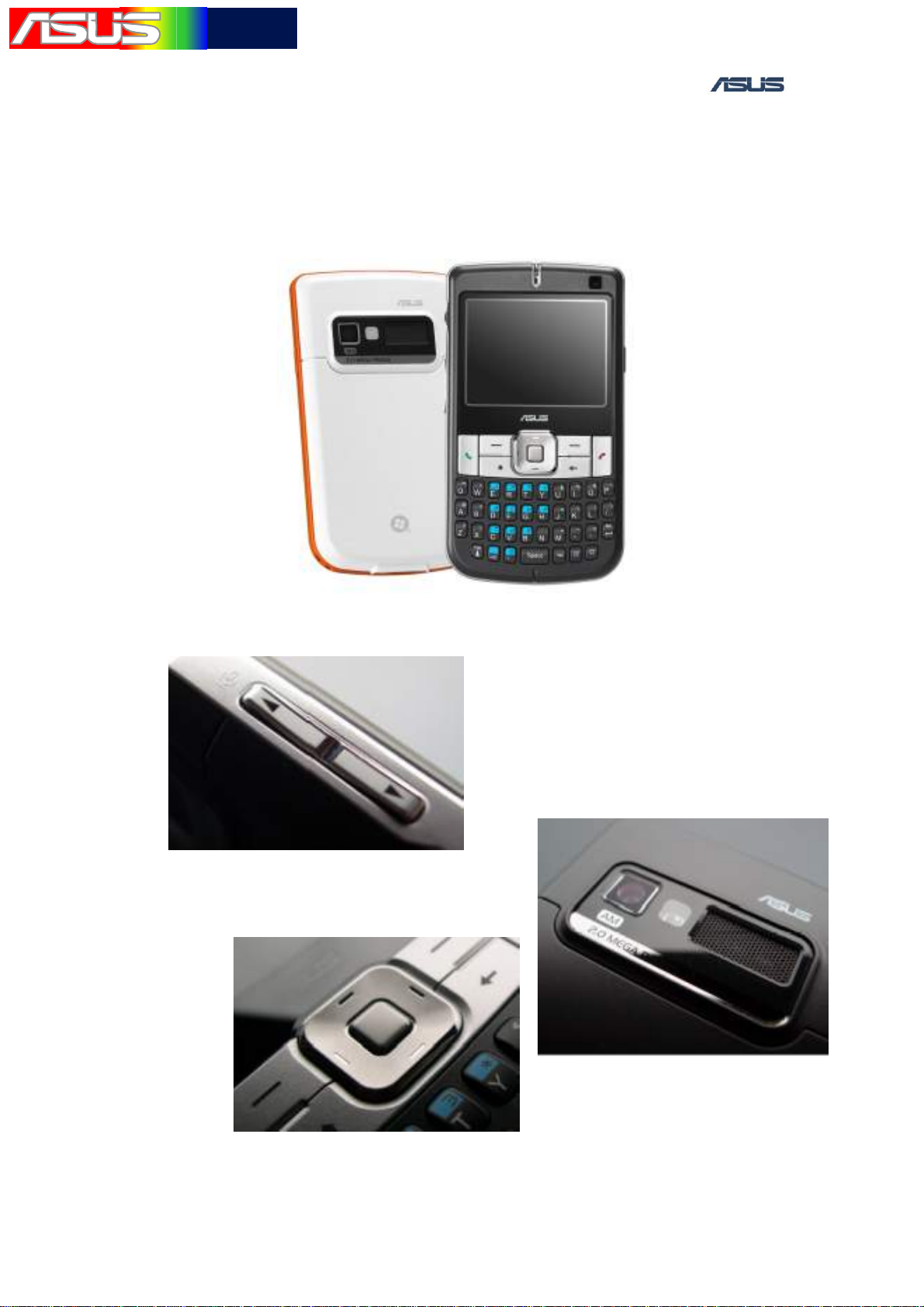
1. APPEARANCE
1.1 BOX APPEARANCE
ASUS Proprietary 6
華華碩碩電電腦腦
TSD ■ Lv3Lv4 Repair Manual
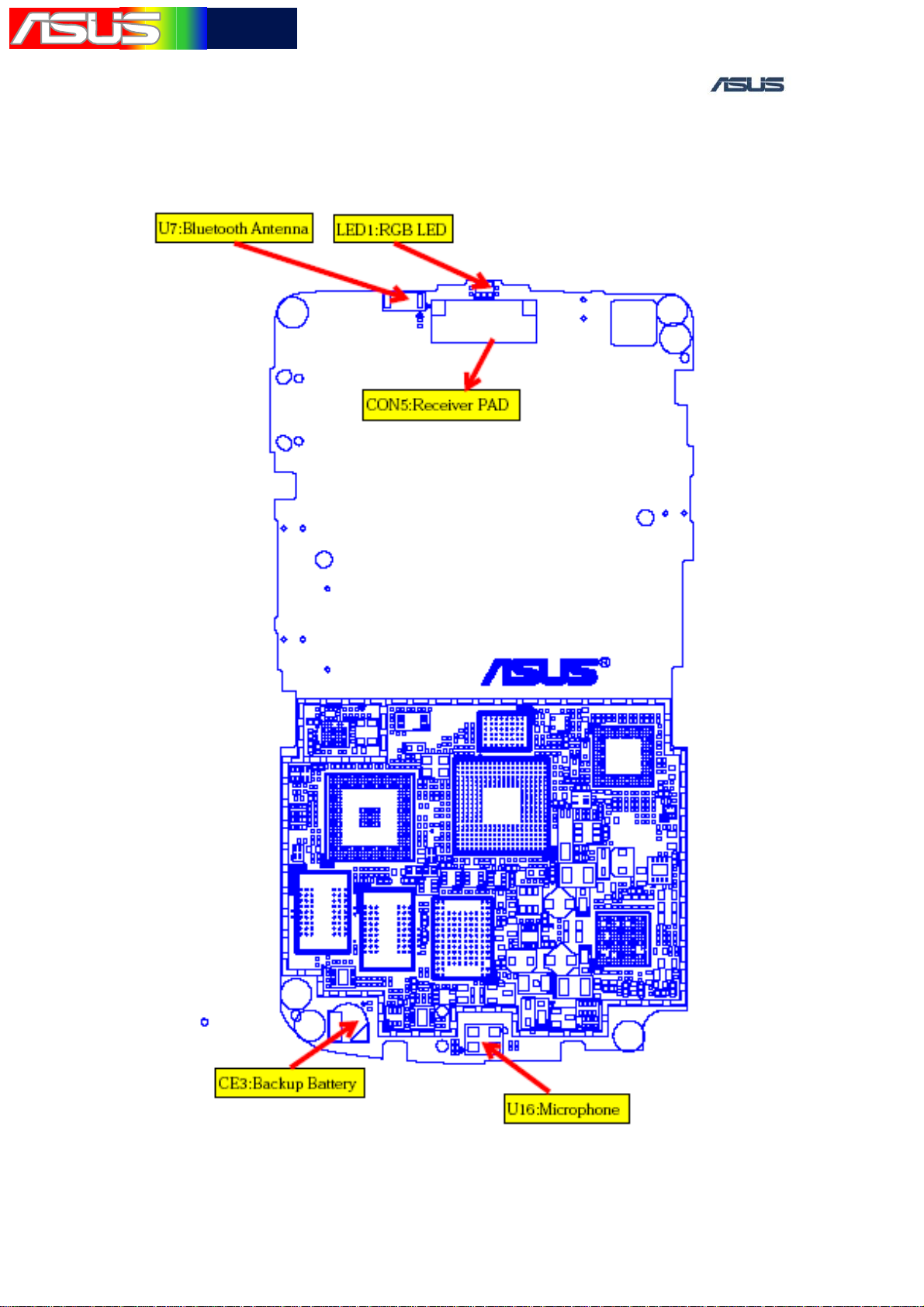
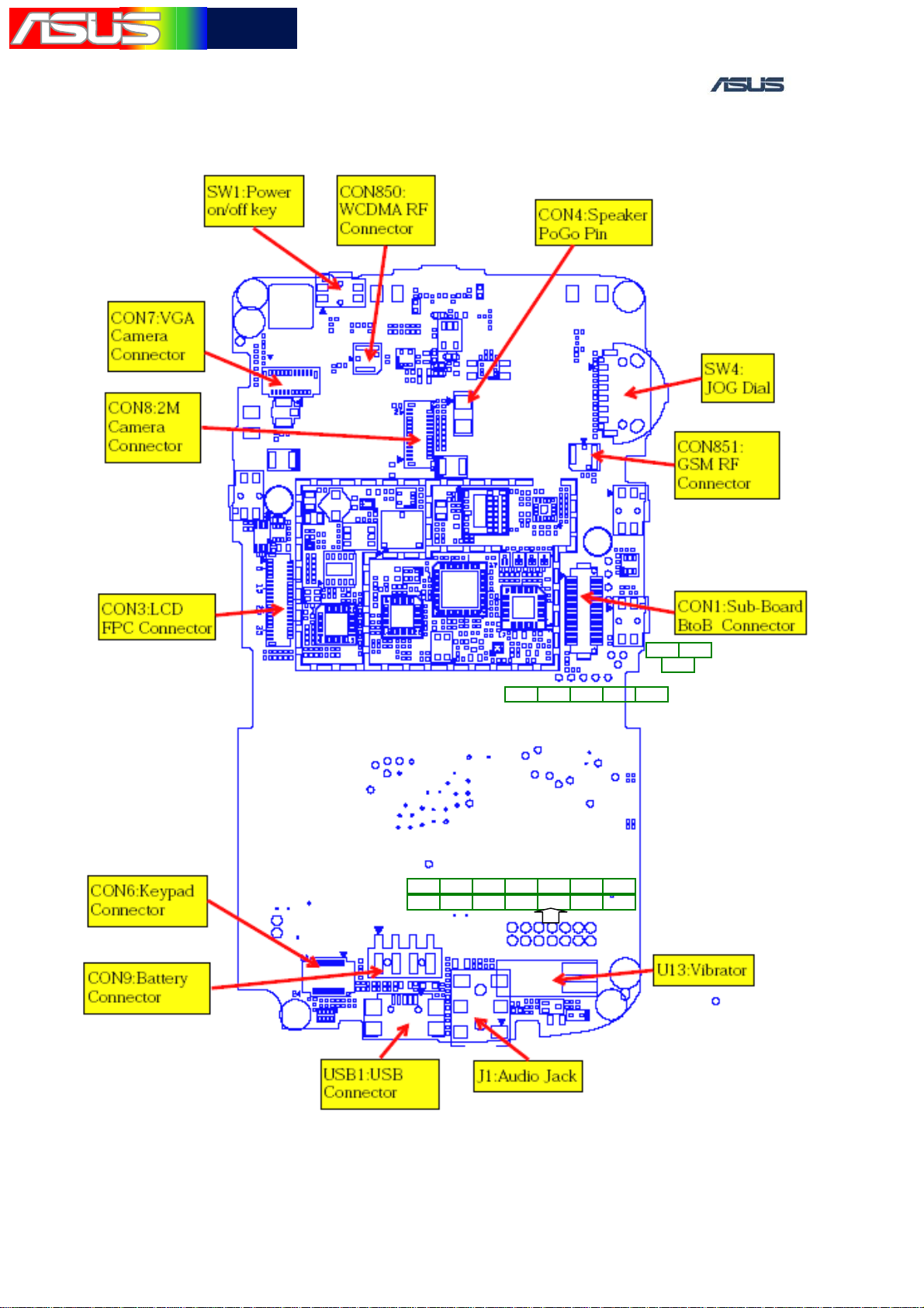
1.2 MAIN COMPONENT NAME & LOCATION
Main Board TOP LAYER
(3)
(4)
(1)
(5)
(6) (7)
(1) Application CPU ( Bulverde PXA270)-U1
(2)
(8)
ASUS Proprietary 7

華華碩碩電電腦腦
TSD ■ Lv3Lv4 Repair Manual
(2)Communication CPU ( Hermon PXA900 )-U17
(3) PSRAM (MT45W1MW16PDGA-70WT)-U18
(4)Cedar Creak-U19
(5) (6)SDRAM-U2、U3
(7)NAND FLASH( M-Systems H3)-U4
(8)PMIC( DA9030 )-U20
ASUS Proprietary 8
華華碩碩電電腦腦
TSD ■ Lv3Lv4 Repair Manual
Main Board BOTTOM LAYER
TP83 TP82
TP36
TP88 TP87 TP84 TP86 TP85
TP75TP50 TP74TP40TP7 TP90 TP92
TP33
TP89TP46 TP35TP47 TP91 TP34
ASUS Proprietary 9
華華碩碩電電腦腦
TSD ■ Lv3Lv4 Repair Manual
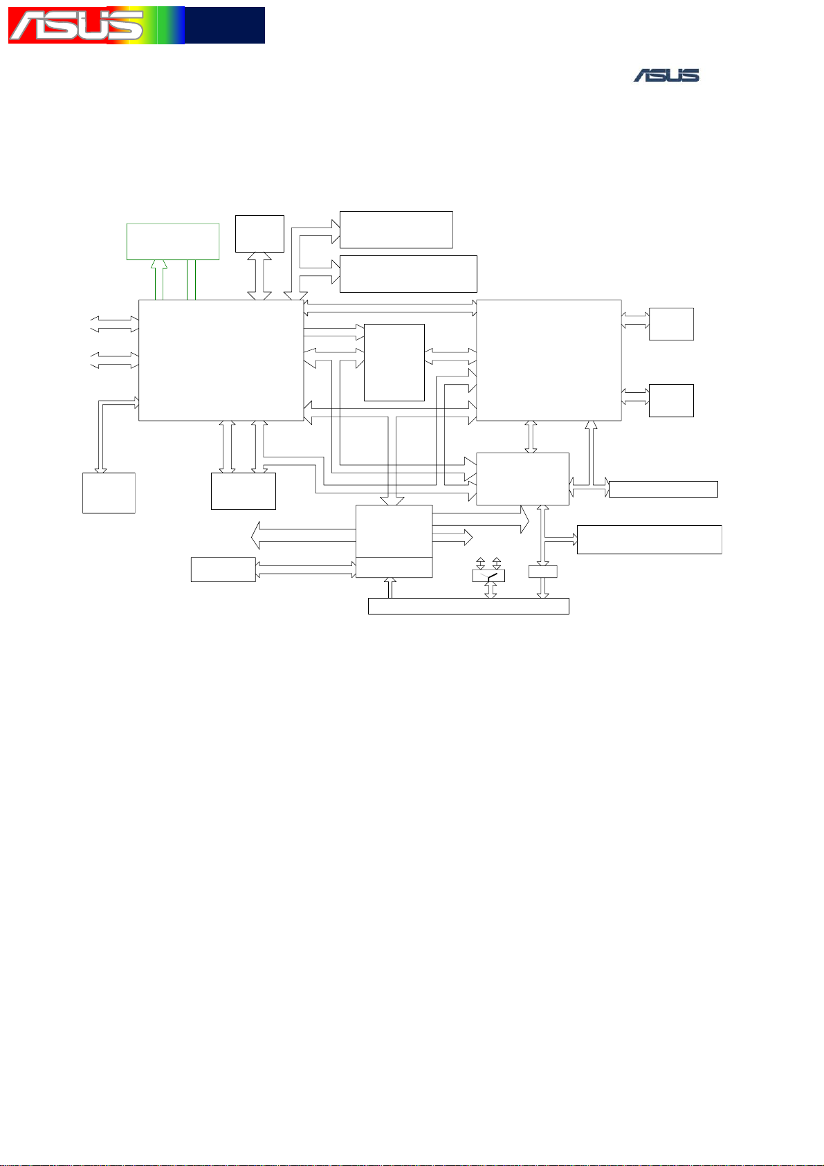
2. BLOCK DIAGRAM
USB
UART
7x8
Qwerty
Keypad
Dual Camera
(2M+VGA)
FPC type
I2C CIF
Bulverde
PXA270
Micro-SD
(push type)
T
R
A
U
_
T
B
BT
(CSR BC-04)
Battery
RGB IF
PCM
Bulverde power
64MB SDRAM
(Samsung/Infineon)
256MB NAND Flash
(M-Systems H3)
MSL
2.46" QVGA
320X240
Land scape
LCD
PWR I2C
PMIC
(Arava)
Charger
VCHG
SSPSSP
Hermon Power
speaker
USB + Headset Jack
Hermon
(Discrete TPBGA)
Cedar Creek
Codec+AFE
HMN
BVD
USB
USB
Hea dset
USB SW .
Amp.
PSRAM
(Micron)
SIM
RF Circuit
MIC + Speaker + Receiver
Audio
ASUS Proprietary 10
華華碩碩電電腦腦
TSD ■ Lv3Lv4 Repair Manual
3. HARDWARE EQUIPMENT
3.1 Digital multimeter
Check if the components are soldered well.
Check if the voltage levels are correct.
Check if the circuit is open or short.
3.2 Oscilloscope
Check the signals waveforms and voltage levels.
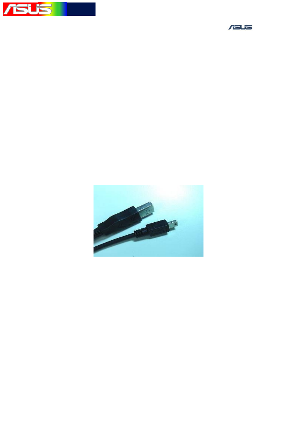
3.3 USB Download Cable
The software bin file can be downloaded into the handset by the M530w
USB download cable. The PC also can connect to the handset by it.
USB Download Cable
3.4 Earpiece
The earpiece can be used for the audio loop test.
3.5 PC
Install the download tool first and execute the download tool.
ASUS Proprietary 11
華華碩碩電電腦腦
TSD ■ Lv3Lv4 Repair Manual
4. DOWNLOAD PROCEDURE
4.1 Introduction
When the handset updates the software, we need to download the
software and data into the NAND flash. The download path is built
up by the USB to Serial port download cable.
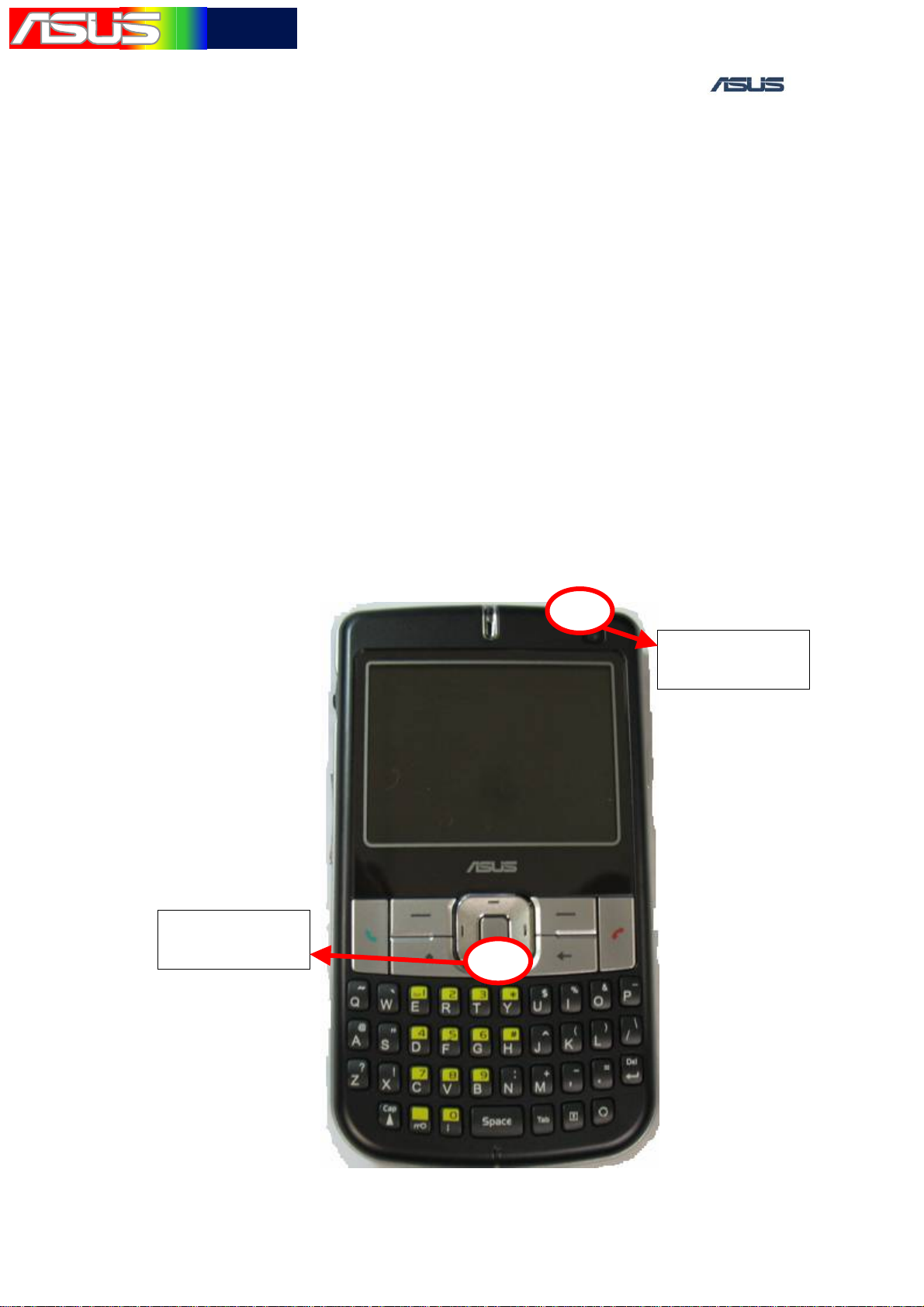
4.2 Operation procedure
1. Set up the power supply voltage and current at 4V and 1A. Connect to
the battery connector positive and negative of the handset.
2. Press the POWER ON Key and Down button. The handset would
power up and enter the download mode.
Power on key
Down button
ASUS Proprietary 12
華華碩碩電電腦腦
TSD ■ Lv3Lv4 Repair Manual
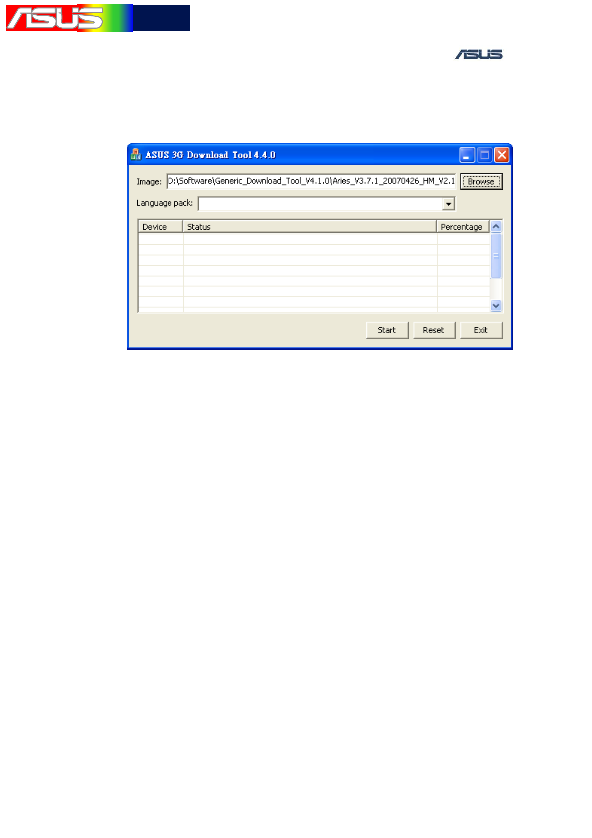
3. The handset is connected the PC by the USB Download Cable.
4. Execute the ASUS 3G Download Tool.exe program, and press
“Browse” to select image.
5. Press Start button to burn image。
4.3 Repair method
1. Check if the USB Connector is soldered poorly or short.
2. Check if the fuse (F5) blew.
3. Check if the U2、U3 and U4(Flash & SDRAM)chips are placed
inversely, soldered poorly or short.
4. Check if the voltages VCC_SDRAM=1.8V and VCC_NFIO
=1.8V are fed the SDRAM and NAND flash. If the VCC_SDRAM
and VCC_NFIO are abnormal, try to change a new DA9030
Power IC.
ASUS Proprietary 13
華華碩碩電電腦腦
TSD ■ Lv3Lv4 Repair Manual
5. LCM DISPLAY
5.1 Introduction
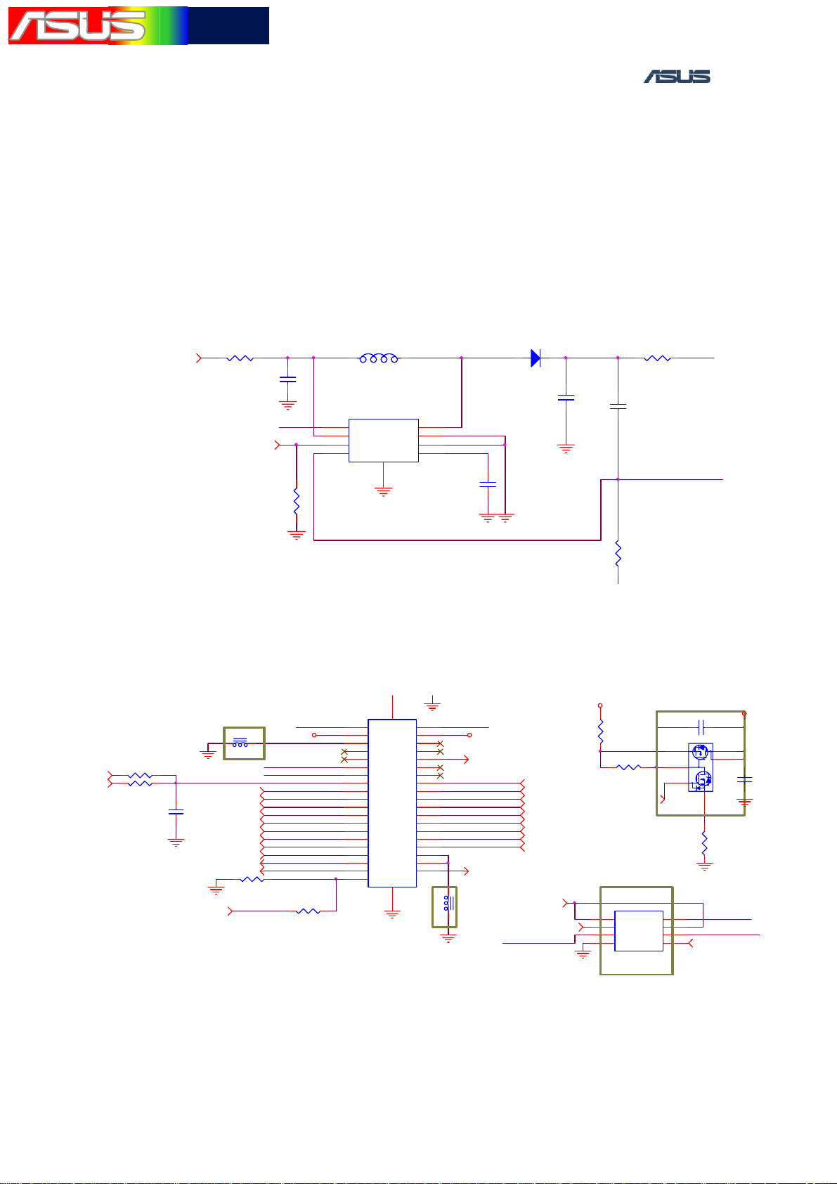
The M530w LCM pixel resolution is 320 * 240. The backlight is white
LED, and the driver IC is MAX8595ZETA (U12).
Backlight Driver
D206
1 2
ZHCS400
BL_DIODE_CA
C211
1
0.47U/25V
2
R223 0Ohm
1
C210
3300P/50V
2
2
R214
16.5Ohm/1%
1
12
BL_AN
BL_CA
VBAT[5,10,11,14..16]
LCD_BL_PWM[2]
12
C208
10UF/6.3V
R224 0Ohm
2
1
BL_AN
2
R215
1MOhm
1
BL_VBAT_IN
L201
10UH
MAX8595ZETA
1
OUT
2
IN
3
CTRL
CS4COMP
U12
9
21
8
LX
7
PGND
GND1
6
5
2
D
N
G
BL_LX
BL_COMP
C212
0.1U/10V
1
2
Backlight Driver
L203
VDD_LCD_2V8
21
R228
0Ohm
nRESET_OUT[2,5,10]
LCD_nRST/DE[2]
R227
$0Ohm
12
12
1
2
GND
LCD_nRST/DE[2]
600Ohm/100M hz
GND
SA_LCDD0[2] SA_LCDD1 [2]
SA_LCDD2[2]
SA_LCDD4][2
C21
SA_LCDD6[2]
$27PF7/50V
SA_LCDD8[2]
SA_LCDD10[2]
SA_LCDD11[2]
SA_LCDD13[2]
SA_LCDD15[2]
SA_LCD_PCLK_IN[2]
SA_LCD_FCLK_IN[2] SA_LCD_LCLK_IN [2]
R226 $0Ohm
GND
LCD_GND_2
LCD_SSPTX_BUF
LCD_SSPCLK_BUF
LCD_nRESET
BVD_B0
LCD_B1
BVD_B2
BVD_B4
LCD_B5
BVD_G1
LCD_G1
BVD_G3
LCD_G3
BVD_G5
LCD_G5
LCD_R1
BVD_R0
LCD_R3 LCD_R4
BVD_R2
LCD_R5
BVD_R4
12
R229
0Ohm
LCD_DE
12
0
CON3
4
1
1
3
3
5
5
7
7
9
9
11
11
13
13
15
15
17
17
19
19
21
21
23
23
25
25
27
27
29
29
31
31
33
33
35
35
37
37
39
39
FPC_CON_39P
1
4
1
E
D
I
S
2
E
D
I
S
GND
2
4
6
8
10
12
14
16
18
20
22
24
26
28
30
32
34
36
38
GND
2
4
6
8
10
12
14
16
18
20
22
24
26
28
30
32
LCD_GND_1
34
36
38
1
600Ohm/100Mhz
2
GND
BL_CABL_AN
LCD_B0
LCD_B2
LCD_B4LCD_B3
LCD_G0
LCD_G2
LCD_G4
LCD_R0
LCD_R2
L202
VDD_LCD_2V8
LCD_SPI_nCS [2]
BVD_B4
BVD_B1
BVD_B3
BVD_G0
BVD_G2
BVD_G4
BVD_R4
BVD_R1
BVD_R3
LCD_PWR_EN[2]
AUD_WLAN_LCD_SSPCLK[2,5,9]
LCD_SSPTX_BUF
SA_LCDD4 [2]
SA_LCDD3 [2]
SA_LCDD5 [2]
SA_LCDD7 [2]
SA_LCDD9 [2]
SA_LCDD15 [2]
SA_LCDD12 [2]
SA_LCDD14 [2]
VLDO18_2V8
1
R225
0Ohm
2
1 2R234
220KOhm
LCD_PWR_EN[2]
1
2
3
4
SN74AUC2G126DCUR
GND
VLCD_2V8
U27
1OE
1A
2Y
GND
VCC
2OE
SS_RC_3
1Y
2A
C220
VDD_LCD_2V8
1000PF/50V
1 2
Q13
34
P
2
6
N
5
FDG6331L_NL
8
7
LCD_SSPCLK_BUF
6
5
1
2
1
GND
S
2
_
S
N
_
R10235
3
KOhm
1
GND
VLCD_2V8
AUD_WLAN_LCD_SSPTX [2,5,9]
C209
2.2UF/6.3V
LCM connector circuit (2)
ASUS Proprietary 14

華華碩碩電電腦腦
TSD ■ Lv3Lv4 Repair Manual
5.2 Measure method
1. Set up the power supply voltage and current at 4V and 1A.
Connect to the battery connector positive and negative of the
handset.
2. Press the POWER ON Key to power on the handset.
3. After entering the MMI Test Mode, select the “Main LCD”
test item. press the Down or up Button to display Red、Green、
Blue、White、gray and Black, and watch the color.
5.3 Repair method
1. When it does Black Screen, check if the LCM connector
soldered poorly or short.
2. When it does White or Black Screen, check if the LCM FPC
oblique or LCM connector no mounted properly.
3. When it does White Screen please check if the U27 is soldered
poorly or short.
4. When the backlight is no function, please check if the
MAX8595ZETA (U12)、C208、C210、C211、C212、L201、
D206、R214、R215、R223 and R224 are placed inversely,
soldered poorly or short.
5. If the above cases are not found, try to change a new LCM.
ASUS Proprietary 15
華華碩碩電電腦腦
TSD ■ Lv3Lv4 Repair Manual
6. USB/CHARGING
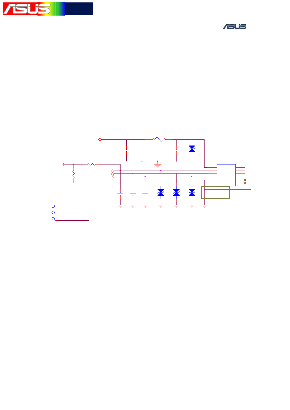
6.1 Introduction
The M530w power is supplied by the Lithium Ion battery. Therefore,
it has the charging function. The M530w can be charged from the
OVP_VCHG_VBUS[10]
470KOhm
2
R207
1
GND
CON_VCHG_VBUS
CON_USBC_DCON_USBC_D+
R205
CON_USBC_DCON_USBC_D+
CARKIT_DET[2]
tpc60t_np_72
tpc60t_np_72
tpc60t_np_72
USB.
750KOhm
1TP33
1TP34
1TP35
6.2 Repair method
1. USB/Charger cannot recognized when they were plugged into the
USB
OVP_VCHG_VBUS
12
OTG_ID[2]
1
2
C205
1
33PF/50V
2
GND
Connector
1
C202
0.1UF/16V
2
C206
C207
1
1
$33PF/50V
$33PF/50V
2
2
1 2
C203
1UF/25V
D203
F5
1.5A/32V
GND
1
2
CON_VCHG_VBUS
1
C204
33PF/50V
H
W
L
2
0
4
0
A
L
M
9
V
$
$V9MLA0402LWH
2
1
H
W
L
D204
2
0
4
0
A
L
M
2
9
V
$
GNDGNDGND GND GND GND
D202
D205
1
2
1
H
W
L
2
0
4
0
A
L
M
2
9
V
$
USB1
1
1
2
2
3
3
4
4
5
5
USB_1X5P
SIDE4
SIDE3
SIDE2
SIDE1
NP_NC2
NP_NC1
11
10
9
8
7
6
USB CON,Check the contact between USB CON pins and the
pads on the main PCB.
2. USB/Charger cannot recognized when they were plugged into the
USB CON,Check if the fuse(F5) blew.
ASUS Proprietary 16
華華碩碩電電腦腦
TSD ■ Lv3Lv4 Repair Manual
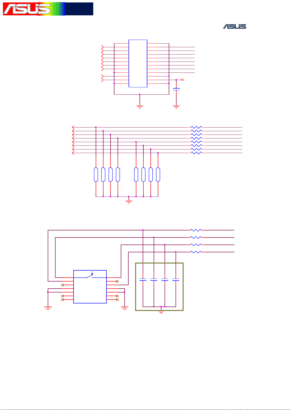
7. KEYPAD
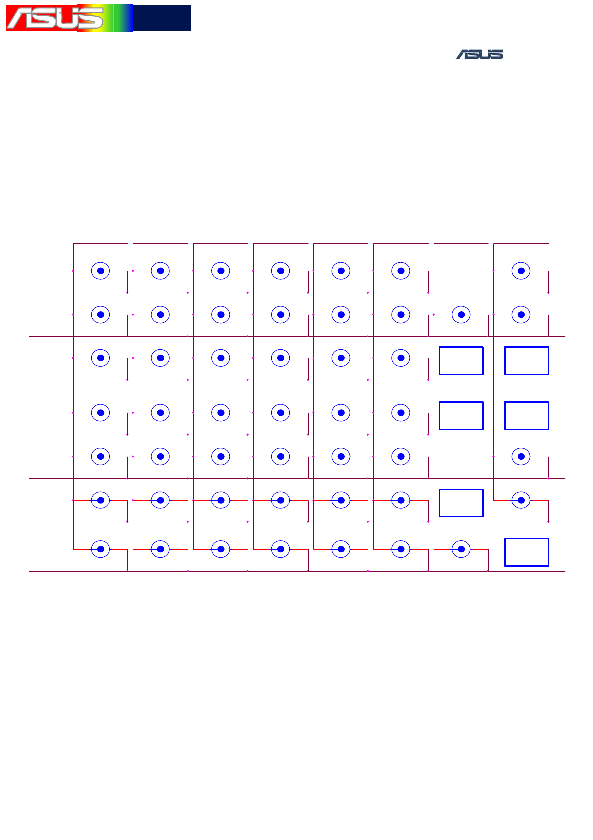
7.1 Introduction
The M530W has 54 keys,some of them are function key.
KP_MKOUT0
KP_MKOUT1
KP_MKOUT2
KP_MKOUT3
KP_MKOUT4
KP_MKOUT5
KP_MKOUT6
KP_MKIN7
KEY36
1 2
Send
KEY21
1 2
Z
KEY1
1 2
Q
KEY12
1 2
S
KEY11
1 2
A
KEY22
1 2
X
KEY32
1 2
Fn
KEY37
1 2
Soft-L
KEY38
1 2
Home
KEY3
1 2
E
KEY2
1 2
W
KEY13
1 2
D
KEY24
1 2
V
KEY23
1 2
C
KEY45
1 2
Left
KEY42
1 2
OK
KEY4
1
2
R
KEY14
1 2
F
KEY15
1 2
G
KEY25
1 2
B
KEY26
1 2
N
KEY43
1 2
Up
KEY44
1 2
Down
KEY6
1 2
Y
KEY5
1 2
T
KEY16
1 2
H
KEY27
1 2
M
KEY34
1 2
?
KEY46
1 2
Right
KEY33
1 2
Space
KEY7
1 2
U
KEY8
1 2
I
KEY17
1 2
J
KEY28
1 2
,
KEY29
1 2
Dot
KEY39
1 2
Soft -R
KEY40
1 2
Back
KEY9
1 2
O
KEY19
1 2
L
KEY18
1 2
K
KEY10
1 2
P
KEY30
1 2
Messa ge
KP_MKIN1KP_MKIN6 KP_MKIN4 KP_MKIN3 KP_MKIN2KP_MKIN5
KEY31
1 2
L-shi ft
Side key
Vol. up
Side key
Vol.down
Side key
Camera
KEY47
1 2
ZERO
KP_MKIN0
KEY35
1 2
R-shift_CAP
KEY41
1 2
End
Jog Dial
push
Jog Dial
down
KEY20
1 2
ENTER
KEY48
1 2
Brightness
Jog Dial
up
Keypad Matrix Circuit
ASUS Proprietary 17
華華碩碩電電腦腦
TSD ■ Lv3Lv4 Repair Manual
R667
PWR_nON_OFF[10] KP_MKIN1[2]
12
0Ohm
C656
0.01UF/50V
PWR_nON_OFF_1 KP_MKIN1_SK
1
2
GND
SW1
TACT_SWITCH_4P
Power_ON
/OFF
GND
6
1
2
5
3
4
7
KP_MKOUT2[2]
R664
12
0Ohm
1
C657
$0.01UF/50V
2
R665
12
0Ohm
1
C659
$0.01UF/50V
2
TACT_SWITCH_4P
GND
Volume Up
KP_MKOUT2_SK
GND
GND
SW2
6
1
2
5
3
4
7
SW5
TACT_SWITCH_4P
Camera
R668
KP_MKOUT5_SK
KP_MKOUT5[2]
0Ohm
C660
$0.01UF/50V
12
1
2
GND
GND
6
1
2
5
3
Volume Down
R666
KP_MKOUT3_SK
4
7
KP_MKOUT3[2]
12
0Ohm
1
C658
$0.01UF/50V
2
GND
SW3
TACT_SWITCH_4P
1
2
5
GND
6
3
4
7
Function Key Circuit
ASUS Proprietary 18
華華碩碩電電腦腦
TSD ■ Lv3Lv4 Repair Manual
CON9
1
1
KP_MKOUT0[2]
KP_MKOUT1[2]
KP_MKOUT2[2]
KP_MKOUT3[2]
KP_MKOUT4[2]
KP_MKOUT5[2]
KP_MKOUT6[2]
LED_DR V1[10]
LED_DR V2[10]
3
3
5
5
7
7
9
9
11
11
13
13
15
15
17
17
19
19
21
21
23
23
BtoB_CON_24P
2
2
4
4
6
6
8
8
10
10
12
12
14
14
16
16
18
18
20
20
22
22
24
24
KP_MKIN0_1
KP_MKIN1_1
KP_MKIN2_1
KP_MKIN3_1
KP_MKIN4_1
KP_MKIN5_1
KP_MKIN6_1
KP_MKIN7_1
VLDO4_3V2
C651
1
1UF/6.3V/10%/0402
2
GND
KP_MKIN0[2]
KP_MKIN1[2]
KP_MKIN2[2]
KP_MKIN3[2]
KP_MKIN4[2]
KP_MKIN5[2]
KP_MKIN6[2]
KP_MKIN7[3]
A
B
C
9
N
R
1
m
h
O
K
0
0
1
2
D
9
N
R
m
h
O
K
0
0
1
9
9
N
N
R
R
5
3
7
m
m
h
h
O
O
K
K
0
0
0
0
1
1
8
6
4
GND
B
A
C
D
0
0
0
1
1
N
N
R
R
1
m
m
h
h
O
O
K
K
0
0
0
0
1
1
2
0
1
1
N
N
R
R
5
3
7
m
m
h
h
O
O
K
K
0
0
0
0
1
1
6
8
4
GND
R651 0Ohm
R652 0Ohm
R653 0Ohm
R654 0Ohm
R655 0Ohm
R656 0Ohm
R657 0Ohm
R658 0Ohm
12
12
12
12
12
12
12
12
KP_MKIN0_1
KP_MKIN1_1
KP_MKIN2_1
KP_MKIN3_1
KP_MKIN4_1
KP_MKIN5_1
KP_MKIN6_1
KP_MKIN7_1
Keypad Connector Circuit
KP_MKOUT6_JOG
KP_MKOUT2_JOG
KP_MKOUT3JOG
1 2R663 0Ohm
1 2R659 0Ohm
1 2R660 0Ohm
1 2R661 0Ohm
KP_MKOUT6
KP_MKIN0KP_MKIN0_JOG
KP_MKOUT2
KP_MKOUT3
SW4
C
1
5
7
9
PUSH
C
1
5
GND1
GND3
P_GND113P_GND2
NP_NC111NP_NC2
SW_6P_8HOLD
GND2
GND4
T
T
2
2
6
6
8
10
14
12
GNDGND
C652
C653
C654
1
1
1
2
2
2
V
V
0
5
/
F
U
1
0
.
0
$
V
0
0
5
5
/
/
F
F
U
U
1
1
0
0
.
.
0
0
$
$
GND
C655
1
2
V
0
5
/
F
U
1
0
.
0
$
JOG DIAL Circuit
ASUS Proprietary 19
華華碩碩電電腦腦
TSD ■ Lv3Lv4 Repair Manual
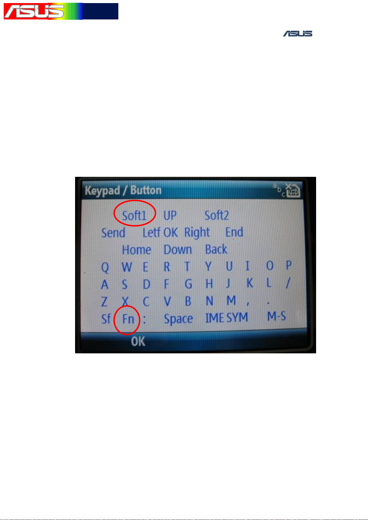
7.2 Measure method
1. Set up the power supply voltage and current at 4V and 1A.
Connect to the battery connector positive and negative of the
handset.
2. Press the POWER ON Key to power on the handset
3. After entering the MMI Test Mode, select the Keypad/Button test
item.
4.
Press every key to verify if each key is OK.
5. Press Soft1 key will leave “Keypad/Button test”, therefore Soft1
key need press last.
7.3 Repair method
1. When the Keypad are no function, check if
a. Keypad connector (CON9) are soldered poorly, open or
short.
b. Serial Resistors ( R651~R658 ) are soldered poorly, open or
ASUS Proprietary 20

華華碩碩電電腦腦
TSD ■ Lv3Lv4 Repair Manual
2. When the function key and JOG DIAL are no function, check if
the sw1、sw2、sw3、sw4、sw 5 and Keypad connector(CON9) are
soldered poorly, damage or short.
3. If the above cases are not found, try to change the Keypad or
Function Key (SW1~SW5).
short.
c. Keypad connector mounted properly
ASUS Proprietary 21

華華碩碩電電腦腦
TSD ■ Lv3Lv4 Repair Manual
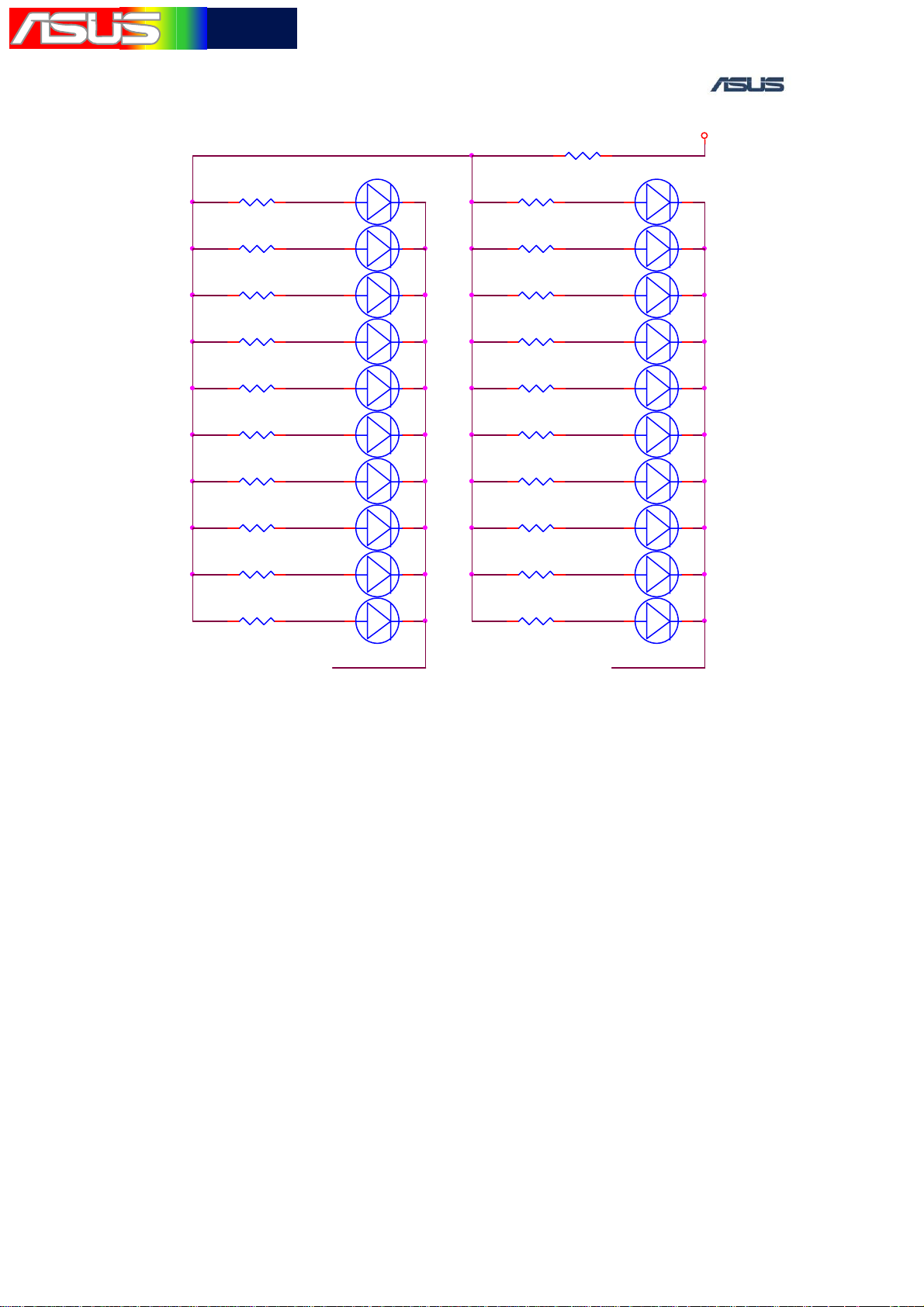
8. KEYPAD LED
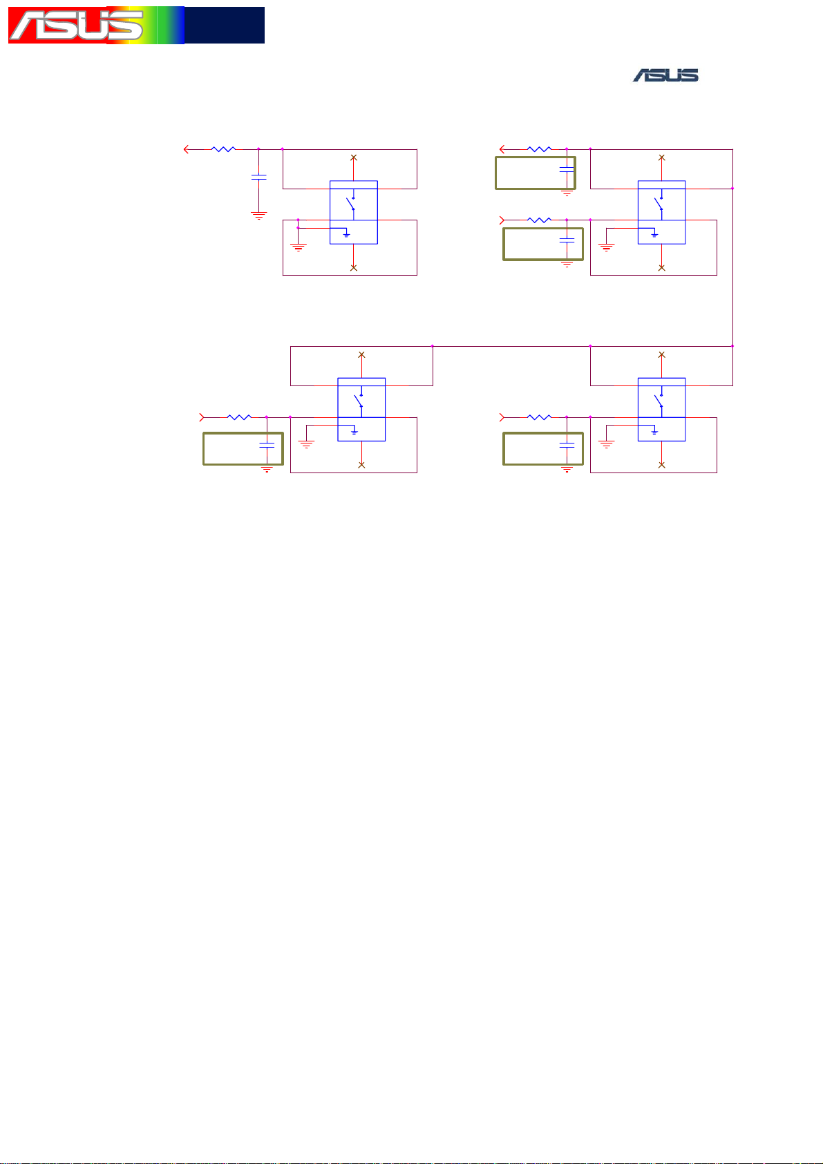
8.1 Introduction
When any key is pressed or the handset is slid, the Keypad LED would
be turned on. If the handset is idle, the LED would be turned off for
saving power.
8.2 Measure method
1. Set up the power supply voltage and current at 4V and 1A.
Connect to the battery connector positive and negative of the
handset.
2. Press the POWER ON Key to power on the handset.
3. After entering the MMI Test Mode, select the “Led test” item.
ASUS Proprietary 22
華華碩碩電電腦腦
TSD ■ Lv3Lv4 Repair Manual
1 2R1
150Ohm
1 2R3
150Ohm
1 2R7
150Ohm
1 2R11
150Ohm
1 2R13
150Ohm
1 2R15
150Ohm
1 2R17
150Ohm
1 2R19
150Ohm
1 2R21
150Ohm
1 2R23
150Ohm
AN_LED1
AN_LED3
AN_LED7
AN_LED11
AN_LED13
AN_LED15
AN_LED17
AN_LED19
AN_LED21
AN_LED23
+
1 2
LED1
+
1 2
LED3
+
1 2
LED7
+
1 2
LED11
+
1 2
LED13
+
1 2
LED15
+
1 2
LED17
+
1 2
LED19
+
1 2
LED21
+
1 2
LED23
LED_DRV1
WHITE
WHITE
WHITE
WHITE
WHITE
WHITE
WHITE
WHITE
WHITE
WHITE
1 2R2
1 2R4
1 2R8
1 2R12
1 2R14
1 2R16
1 2R18
1 2R20
1 2R22
1 2R24
150Ohm
150Ohm
150Ohm
150Ohm
150Ohm
150Ohm
150Ohm
150Ohm
150Ohm
150Ohm
R25
1 2
0Ohm
AN_LED2
AN_LED4
AN_LED8
AN_LED12
AN_LED14
AN_LED16
AN_LED18
AN_LED20
AN_LED22
AN_LED24
+
1 2
LED2
+
1 2
LED4
+
1 2
LED8
+
1 2
LED12
+
1 2
LED14
+
1 2
LED16
+
1 2
LED18
+
1 2
LED20
+
1 2
LED22
+
1 2
LED24
LED_DRV2
VLDO4_3V2
WHITE
WHITE
WHITE
WHITE
WHITE
WHITE
WHITE
WHITE
WHITE
WHITE
8.3 Measure method
1. When the Keypad all LEDs can not turn on, check if the
KEYPAD connector (CON1 and CON2)、R25 are soldered
poorly, damage, open or short.
2. When the Keypad not all LEDs can not turn on, change the
new Keypad.
3.
If the above cases are not found, change the new Keypad.
KEYPAD LED circuit
ASUS Proprietary 23
華華碩碩電電腦腦
TSD ■ Lv3Lv4 Repair Manual
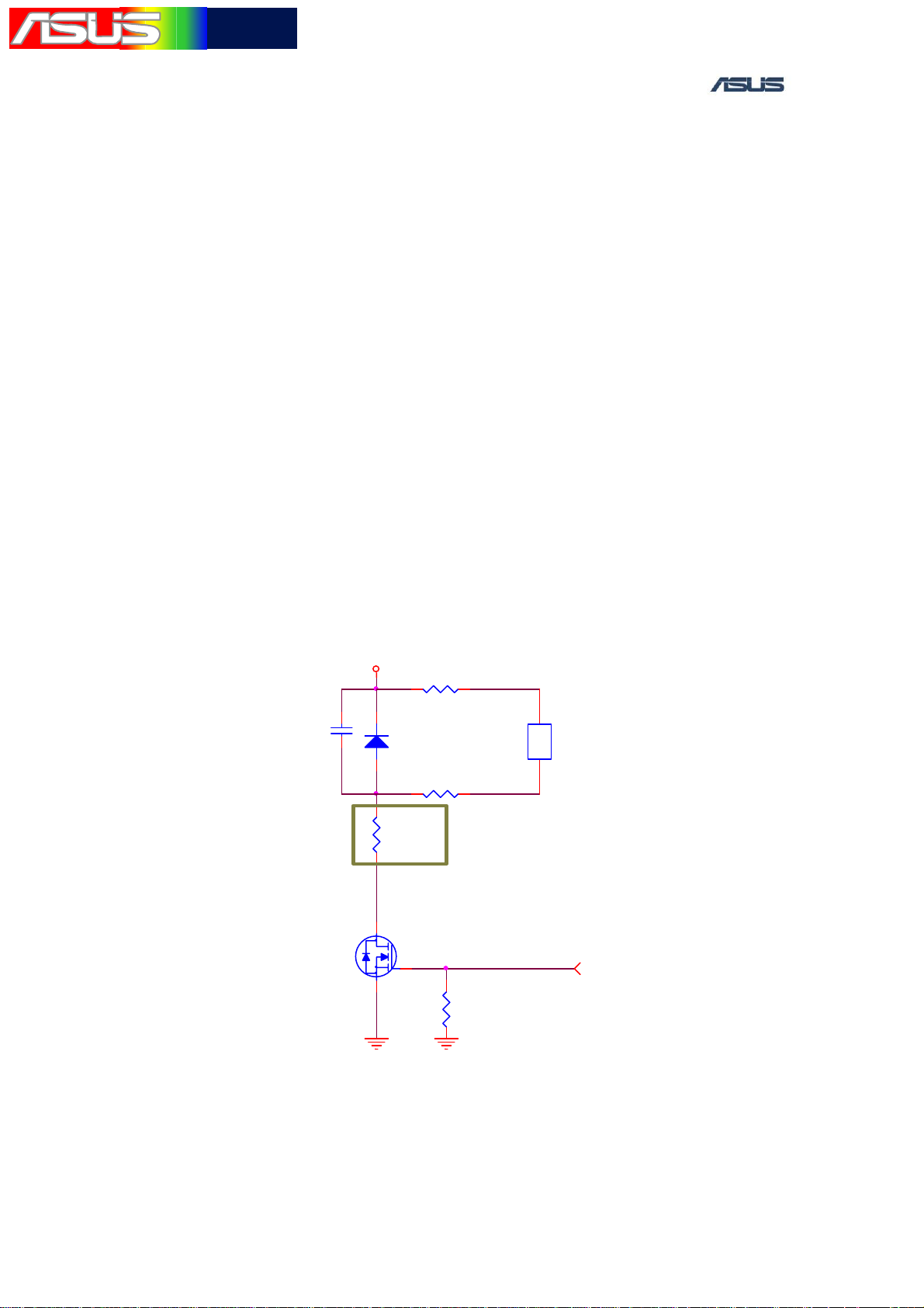
9. VIBRATOR
9.1 Introduction
The Handset controls the vibrator by the PMIC- DA9030(U20).
9.2 Measure method
1. Set up the power supply voltage and current at 4V and 1A.
Connect to the battery connector positive and negative of the
handset.
2. Press the POWER ON Key to power on the handset.
3. After entering the MMI Test Mode, select the “set
Vibrator“ test item. Press ”on”,the vibrator should vibrate.
VBAT
VIB_IN
12 R216
0Ohm
2
1
C213
0.1UF/10V
2
umt3_rohm ==>
sot_416
D207
1SS400
1
VIB_D_AN
2
1
D
_
S
O
M
_
B
I
V
3
D
S
1
GND GND
R220
5.1Ohm
2
G
R218
0Ohm
Q3
SI1012R
1
2
12
R222
100KOhm
VIB_OUT
2
2
1
1
U13
$VIBRATOR_2P
VIBRATOR_EN [10]
Vibrator circuit
ASUS Proprietary 24

華華碩碩電電腦腦
TSD ■ Lv3Lv4 Repair Manual
9.3 Repair method
1. Check if the R216、R218、R220、R222、D207、Q3、C213are
placed inversely, soldered poorly, damage, open or short.
2. If the voltage of each pin is normal, change a new vibrator.
ASUS Proprietary 25
華華碩碩電電腦腦
TSD ■ Lv3Lv4 Repair Manual
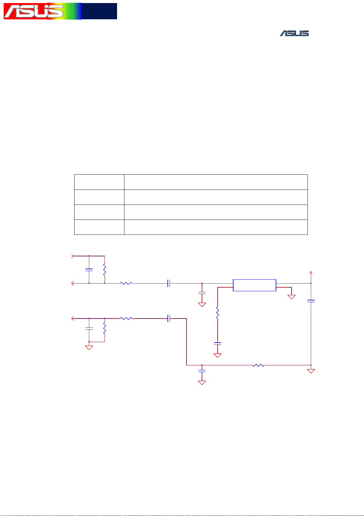
10. ACOUSTICS
10.1 HANDSET
10.1.1 Introduction
The purpose of this test is mainly verifying the handset microphone、
speaker and receiver function.
M530w has three kinds of the audio output and input
Type Comment
Handset Utilize the handset microphone and receiver.
Hand free Utilize the handset microphone and speaker.
Headset Utilize the handset earpiece.
MICAMP_O[9]
2
1
C319
100PF/50V
C325
100PF/50V
VSS_CCA
2
1
2
MIC2_IN[9]
MIC2_IP[9]
R317
100KOhm/1%
1
30KOhm/1%
30KOhm/1%
2
R321
100KOhm/1%
1
1 2
R318
R320
1 2
Microphone
MICOB_IN MICOB_0
MICOB_IP
C320
12
1UF/6.3V
C323
12
1UF/6.3V
C321
100PF/50V
VSS_MIC
MICOB_VD
C334
100PF/50V
VSS_MIC
1
C
G
2
_
B
O
C
I
1
M
2
2
C
G
1
_
B
O
C
I
M
2
1
VSS_MIC
2
1
U16
1
OUTPUT
GAIN CONTROL2GND
SPM0208HE5-SB
R319
0Ohm
C324
1UF/10V
POWER
R326
12
0Ohm
4
3
VLDO13_MICBIAS
VSS_MIC
1
C322
10UF/10V
2
VSS_MIC
Microphone circuit
ASUS Proprietary 26
華華碩碩電電腦腦
TSD ■ Lv3Lv4 Repair Manual
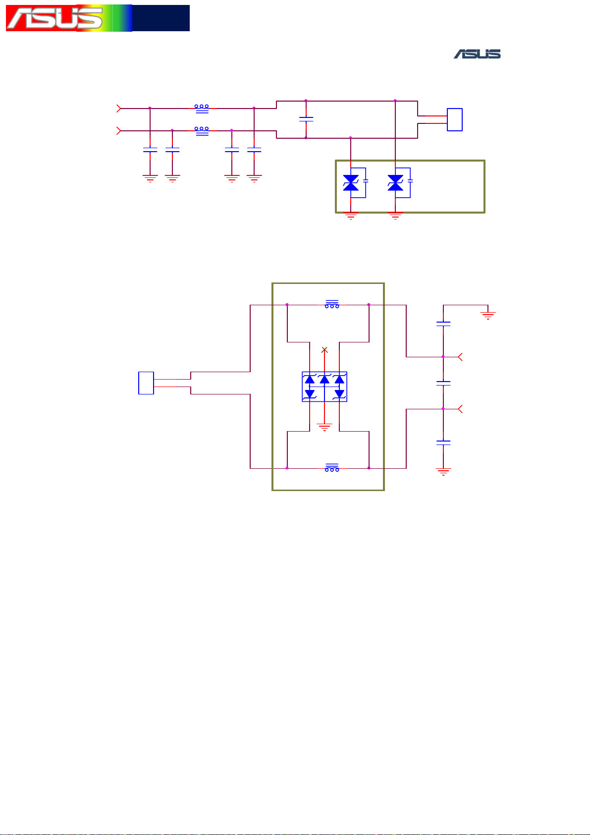
Receiver
L306 1400Ohm/1Ghz
RE_N[9]
RE_P[9]
1
C339
2
2 1
L307 1400Ohm/1Ghz
2 1
1
C338
2
1
C332
2
2
1
1
C333
2
RE_N_OUT
C328
$100PF/50V
RE_P_OUT
1
CON5
1
1
2
2
$RECEIVER_2P
1
GNDGND
$33PF/50V
$33PF/50V
CON4
1
1
2
2
POGO_2PIN
Speaker_CONNECTOR
GND
D308
331K
2
GND
GND
$33PF/50V
GND
$33PF/50V
D307
331K
2
Receiver circuit
L308
21
330Ohm/100Mhz
Speaker_IN_P
Speaker_IN_N
Speaker circuit
56
D
N
G
1 2
GND
330Ohm/100Mhz
4
D309
PACDN045YB6
3
L309
21
1
2
1
2
1
2
GND
C326
27PF/50V
SP_OUT1 [10]
C327
27PF/50V
SP_OUT2 [10]
C331
27PF/50V
GND
ASUS Proprietary 27
華華碩碩電電腦腦
TSD ■ Lv3Lv4 Repair Manual
10.1.2 Measure method
1. Set up the power supply voltage and current at 4V and 1A.
Connect to the battery connector positive and negative of the
handset.
2. Press the POWER ON Key to power on the handset.
3. After entering the MMI Test Mode, select the “Audio” test
item. Press ”play”, The melody can be heard from the speaker.
4. Enter the MMI Test Mode, and select the “Audio” test item.
Press ”recode”, blow the handset microphone hole slightly.
The blowing voice can be heard form the receiver.
5. Enter the MMI Test Mode; select the “Receiver” test item.
The single tone voice can be heard from the receiver.
10.1.3 Repair method
1. When the microphone can’t work
a. check if the microphone circuit are soldered poorly,
b. Check rubber set properly.
damage or short.
c. If the above cases are not found, change the new
microphone.
2. When the speaker can’t work
ASUS Proprietary 28
 Loading...