

Page 1
E460
R
K7M-RM Slot A Motherboard
Motherboard Settings
This section explains in detail how to change your motherboard’ s function settings
through the use of switches and/or jumpers.
W ARNING! Computer motherboards and expansion cards contain very delicate
Integrated Circuit (IC) chips. T o protect them against damage from static electricity, you should follow some precautions whenever you work on your computer.
1. Unplug your computer when working on the inside.
2. Use a grounded wrist strap before handling computer components. If you do
not have one, touch both of your hands to a safely grounded object or to a
metal object, such as the power supply case.
3. Hold components by the edges and try not to touch the IC chips, leads or
connectors, or other components.
4. Place components on a grounded antistatic pad or on the bag that came with
the component whenever the components are separated from the system.
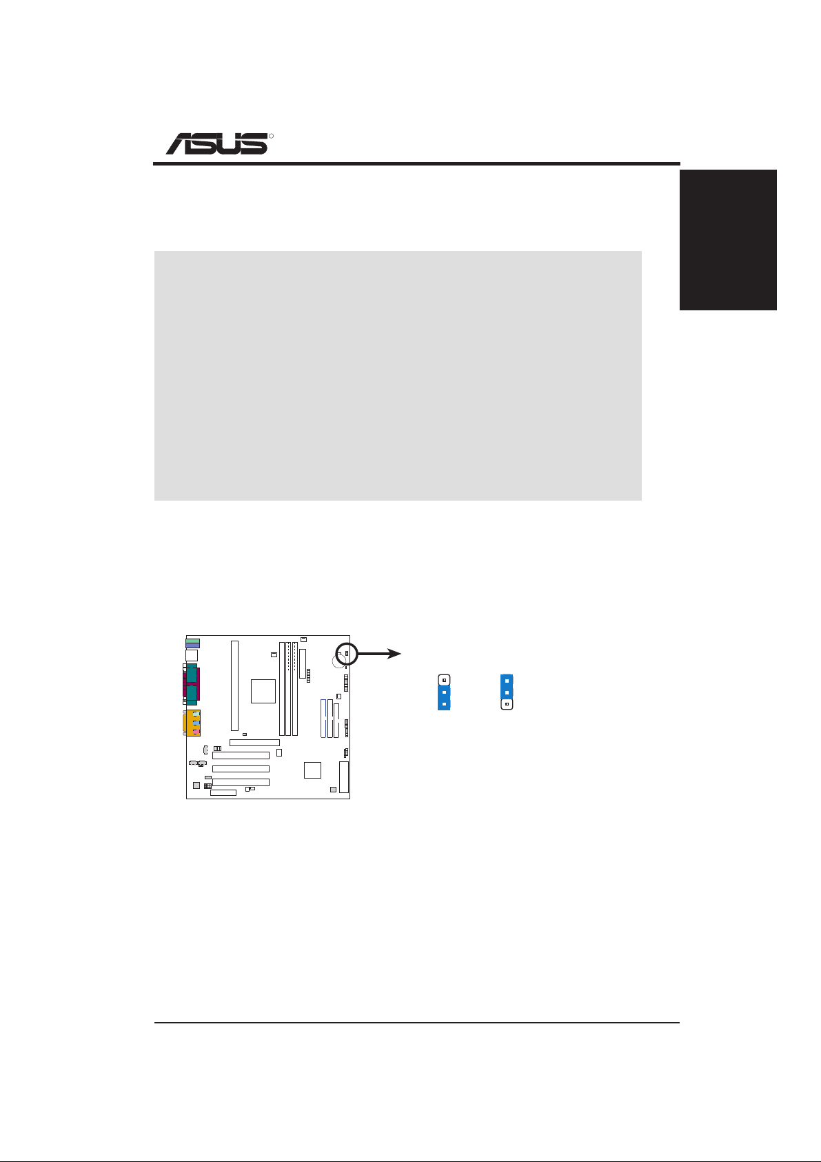
1) Vaux Setting (3VSBSLT)
This jumper allows you to select the voltage supplied to add-in PCI cards that
require Vaux power.
010101
PARALLEL PORT
3VSBSLT
3
2
1
Add 3 Volt Add 3 VSB
3
2
1
K7M-RM
MB SETTINGS
K7M-RM
K7M-RM PCI Vaux Selection
ASUS K7M-RM Motherboard
1
Page 2
R
K7M-RM Slot A Motherboard
MB SETTINGS
K7M-RM
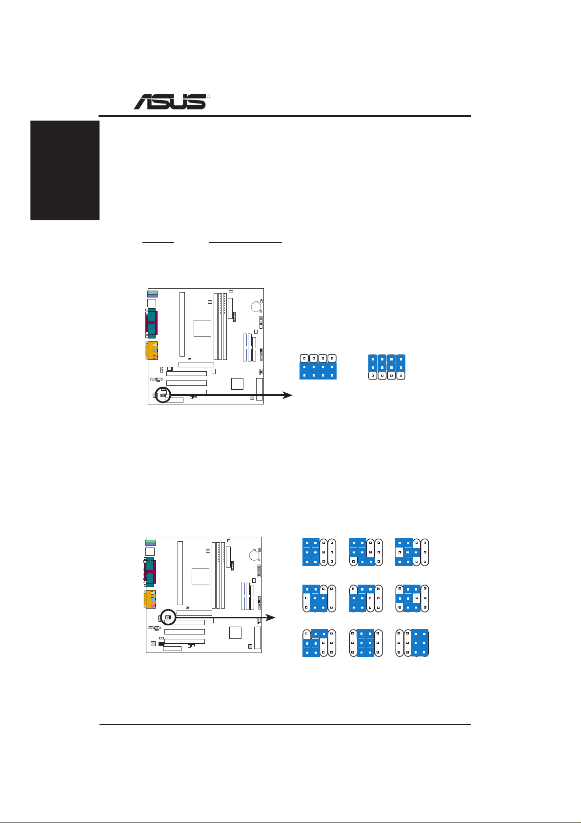
2) Onboard Audio Setting (AUDIOCODEC)
The onboard audio CODEC may be enabled or disabled using all of these jumpers. Disable the onboard audio CODEC if you are using an ISA or PCI audio
card on any of the expansion slots or a primary AMR on the AMR slot. If using
an ISA or PCI audio expansion card, Onboard AC’97 Audio Controller in I/O
Device Configuration of the BIOS must also be disabled.
NOTE: This setting is available only on motherboards with the onboard audio option.
Setting AUDIOCODEC
Enable [1-2] [1-2] [1-2] [1-2] (default)
Disable [2-3] [2-3] [2-3] [2-3]
010101
PARALLEL PORT
K7M-RM
K7M-RM Audio Codec Setting
Enable
Onboard
Audio Codec
SPK
3
2
1
ADN#
AUD_EN2
AUD_EN1
Disable
Onboard
Audio Codec
SPK
3
2
1
ADN#
AUD_EN2
AUD_EN1
3) Voltage Regulator Output Setting (VID1, VID2, VID3)
This jumpers allow you to manually adjust the CPU core voltage. It is recommended to use CPU Default as the CPU core voltage. CPU Default means the
Vcore is generated according to the CPU VID configuration. For each jumper
setting, there are two voltage options, depending on the CPU used.
3214 3214 3214
2/2.05Volts
1.7/1.75Volts
1.4/1.45Volts 1.3/1.35olts
1.9/1.95Volts
3214 3214 3214
1.6/1.65Volts
3214 3214 3214
1.8/1.85Volts
1.5/1.55Volts
CPU Default
010101
PARALLEL PORT
K7M-RM
K7M-RM CPU Core Voltage
Selection
VID3
VID2
VID1
VID3
VID2
VID1
VID3
VID2
VID1
2
ASUS K7M-RM Motherboard
Page 3

R
K7M-RM Slot A Motherboard
4) CPU External Frequency Setting (DSW1)
This option tells the clock generator what frequency to send to the CPU, SDRAM,
and the chipset. This allows the selection of the CPU’ s External frequency . The
CPU external frequency multiplied by the Frequency Multiple equals the CPU’ s
Internal frequency (the advertised CPU speed). The CPU is running at the same
speed as the SDRAM.
NOTE: The motherboard only supports PC100 (100MHz) DIMMs for system
memory.
K7M-RM
MB SETTINGS
010101
PARALLEL PORT
K7M-RM
DSW1
CPU/SDRAM
CPU/SDRAM
ON
OFF
ON
OFF
ON
12
100MHz 103MHz
ON
12
105MHz 110MHz
ON
12
ON
12
K7M-RM CPU External Frequency Selection
5) 3.3V Power Source Setting (JP3001–JP3008)
This jumper lets you select the onboard 3.3V from the motherboard if your
ATX power supply does not have a 3.3V lead. Do not place jumper caps over
these jumpers if your power supply does not have a 3.3V lead or you want the
motherboard to supply the 3.3V power.
010101
JP3001
PARALLEL PORT
JP3001–JP3008
3.3V from Power Supply
K7M-RM
K7M-RM 3.3V Power Source Setting
ASUS K7M-RM Motherboard
JP3008
(Default)
3.3V from Motherboard
3
Page 4

R
K7M-RM Slot A Motherboard
MB SETTINGS
K7M-RM
6) CMOS Real Time Clock (RTC) RAM Setting (R181)
If you forgot your system passwords (Supervisor Password and User Password, which may be set during BIOS Setup), you can clear the passwords by
erasing the CMOS Real Time Clock (RTC) RAM. The RAM data containing
the password information is powered by the onboard button cell battery. To
erase the RTC RAM: (1) Unplug your computer, (2) remove the battery, (3)
Short the solder points, (4) reinsert the battery , (5) Turn ON your computer, (6)
Hold down the <Del> key during bootup and enter BIOS setup to reenter user
preferences.
010101
PARALLEL PORT
K7M-RM
K7M-RM Clear RTC RAM
JP3011
Short solder points
to Clear CMOS
SPECIFICATIONS AND INFORMATION CONTAINED IN THIS MANUAL ARE FURNISHED FOR INFORMATIONAL USE ONLY, AND ARE SUBJECT TO CHANGE AT
ANY TIME WITHOUT NOTICE, AND SHOULD NOT BE CONSTRUED AS A COMMIT MENT BY ASUSTeK COMPUTER INC. (ASUS). ASUS ASSUMES NO RESPONSIBILITY OR LIABILITY FOR ANY ERRORS OR INACCURACIES THAT MAY APPEAR IN
THIS MANUAL, INCLUDING THE PRODUCTS AND SOFTWARE DESCRIBED IN IT.
Copyright © 1999 ASUSTeK COMPUTER INC. All Rights Reserved.
4
ASUS K7M-RM Motherboard
 Loading...