

Page 1

K8N4-E
Deluxe
Motherboard
Page 2

E2009E2009
E2009
E2009E2009
Revision Edition V2Revision Edition V2
Revision Edition V2
Revision Edition V2Revision Edition V2
March 2005March 2005
March 2005
March 2005March 2005
Copyright © 2005 ASUSTeK COMPUTER INC. All Rights Reserved.
No part of this manual, including the products and software described in it, may be reproduced,
transmitted, transcribed, stored in a retrieval system, or translated into any language in any form
or by any means, except documentation kept by the purchaser for backup purposes, without the
express written permission of ASUSTeK COMPUTER INC. (“ASUS”).
Product warranty or service will not be extended if: (1) the product is repaired, modified or
altered, unless such repair, modification of alteration is authorized in writing by ASUS; or (2)
the serial number of the product is defaced or missing.
ASUS PROVIDES THIS MANUAL “AS IS” WITHOUT WARRANTY OF ANY KIND, EITHER
EXPRESS OR IMPLIED, INCLUDING BUT NOT LIMITED TO THE IMPLIED WARRANTIES
OR CONDITIONS OF MERCHANTABILITY OR FITNESS FOR A PARTICULAR PURPOSE.
IN NO EVENT SHALL ASUS, ITS DIRECTORS, OFFICERS, EMPLOYEES OR AGENTS BE
LIABLE FOR ANY INDIRECT, SPECIAL, INCIDENTAL, OR CONSEQUENTIAL DAMAGES
(INCLUDING DAMAGES FOR LOSS OF PROFITS, LOSS OF BUSINESS, LOSS OF USE
OR DATA, INTERRUPTION OF BUSINESS AND THE LIKE), EVEN IF ASUS HAS BEEN
ADVISED OF THE POSSIBILITY OF SUCH DAMAGES ARISING FROM ANY DEFECT OR
ERROR IN THIS MANUAL OR PRODUCT.
SPECIFICATIONS AND INFORMATION CONTAINED IN THIS MANUAL ARE FURNISHED
FOR INFORMATIONAL USE ONLY, AND ARE SUBJECT TO CHANGE AT ANY TIME
WITHOUT NOTICE, AND SHOULD NOT BE CONSTRUED AS A COMMITMENT BY ASUS.
ASUS ASSUMES NO RESPONSIBILITY OR LIABILITY FOR ANY ERRORS OR
INACCURACIES THAT MAY APPEAR IN THIS MANUAL, INCLUDING THE PRODUCTS
AND SOFTWARE DESCRIBED IN IT.
Products and corporate names appearing in this manual may or may not be registered
trademarks or copyrights of their respective companies, and are used only for identification or
explanation and to the owners’ benefit, without intent to infringe.
iiii
ii
iiii
Page 3

Contents
Notices ............................................................................................... vii
Safety information ............................................................................ viii
About this guide ................................................................................. ix
K8N4-E Deluxe specifications summary .............................................. xi
Chapter 1:Chapter 1:
Chapter 1:
Chapter 1:Chapter 1:
1.1 Welcome! .............................................................................. 1-1
1.2 Package contents ................................................................. 1-1
1.3 Special features .................................................................... 1-2
1.3.1 Product highlights ................................................... 1-2
1.3.2 ASUS Proactive feature .......................................... 1-5
1.3.3 Innovative ASUS features ....................................... 1-5
Chapter 2:Chapter 2:
Chapter 2:
Chapter 2:Chapter 2:
2.1 Before you proceed .............................................................. 2-1
2.2 Motherboard overview .......................................................... 2-2
2.2.1 Placement direction ................................................ 2-2
2.2.2 Screw holes ............................................................ 2-2
2.2.3 Motherboard layout ................................................ 2-3
2.2.4 Layout Contents ..................................................... 2-4
2.3 Central Processing Unit (CPU) .............................................. 2-6
Product introductionProduct introduction
Product introduction
Product introductionProduct introduction
Hardware informationHardware information
Hardware information
Hardware informationHardware information
2.4 System memory ................................................................... 2-8
2.4.1 Overview ................................................................. 2-8
2.4.2 Memory Configurations ........................................... 2-8
2.4.3 Installing a DDR DIMM ........................................... 2-12
2.4.4 Removing a DDR DIMM .......................................... 2-12
2.5 Expansion slots ................................................................... 2-13
2.5.1 Installing an expansion card .................................. 2-13
2.5.2 Configuring an expansion card..............................2-13
2.5.3 Interrupt assignments .......................................... 2-14
2.5.4 PCI slots ................................................................ 2-15
2.5.5 PCI Express x16 slot ............................................. 2-15
2.5.6 PCI Express x1 slot ............................................... 2-15
iiiiii
iii
iiiiii
Page 4

Contents
2.6 Jumpers .............................................................................. 2-16
2.7 Connectors ......................................................................... 2-18
2.7.1 Rear panel connectors .......................................... 2-18
2.7.2 Internal connectors ............................................... 2-20
Chapter 3:Chapter 3:
Chapter 3:
Chapter 3:Chapter 3:
3.1 Starting up for the first time................................................ 3-1
3.2 Powering off the computer .................................................. 3-2
3.2.1 Using the OS shut down function ........................... 3-2
3.2.2 Using the dual function power switch .................... 3-2
3.3 ASUS POST Reporter™ .......................................................... 3-3
3.3.1 Vocal POST messages ............................................ 3-3
3.3.2 Winbond Voice Editor ............................................. 3-5
Chapter 4:Chapter 4:
Chapter 4:
Chapter 4:Chapter 4:
4.1 Managing and updating your BIOS ........................................ 4-1
4.1.1 Creating a bootable floppy disk .............................. 4-1
4.1.2 AwardBIOS Flash Utility .......................................... 4-2
4.1.3 ASUS EZ Flash utility .............................................. 4-6
4.1.4 ASUS CrashFree BIOS 2 utility ................................ 4-7
4.1.5 ASUS Update utility ................................................ 4-8
Powering upPowering up
Powering up
Powering upPowering up
BIOS setupBIOS setup
BIOS setup
BIOS setupBIOS setup
4.2 BIOS Setup program ........................................................... 4-11
4.2.1 BIOS menu bar ...................................................... 4-12
4.2.2 Legend bar ........................................................... 4-12
4.3 Main Menu........................................................................... 4-14
4.3.1 System Time ......................................................... 4-14
4.3.2 System Date ......................................................... 4-14
4.3.3 Language .............................................................. 4-14
4.3.4 Legacy Diskette A ................................................ 4-14
4.3.5 HDD SMART Monitoring ........................................ 4-15
4.3.6 Installed Memory .................................................. 4-15
4.3.7 Primary and Secondary IDE Master/Slave ............. 4-15
4.3.8 First, Second, Third, and Fourth SATA Master ..... 4-17
iviv
iv
iviv
Page 5

Contents
4.4 Advanced Menu .................................................................. 4-19
4.4.1 CPU configuration ................................................. 4-20
4.4.2 PCIPnP ................................................................... 4-22
4.4.3 Onboard device configuration ............................. 4-24
4.4.4 JumperFree Configuration .................................... 4-30
4.4.5 LAN Cable Status ................................................. 4-32
4.4.6 PEG Link Mode ...................................................... 4-33
4.4.7 Speech Configuration ........................................... 4-34
4.4.8 Instant Music ........................................................ 4-35
4.5 Power Menu ........................................................................ 4-36
4.5.1 ACPI Suspend Type............................................... 4-36
4.5.2 ACPI APIC Support ................................................ 4-36
4.5.3 APM configuration ................................................ 4-37
4.5.4 Hardware monitor ................................................. 4-40
4.6 Boot Menu .......................................................................... 4-41
4.6.1 Boot Device Priority .............................................. 4-41
4.6.2 Removable drives ................................................. 4-42
4.6.3 Hard Disk Drives ................................................... 4-42
4.6.4 CD-ROM drives ...................................................... 4-43
4.6.5 Boot settings configuration .................................. 4-43
4.6.6 Security ................................................................ 4-45
4.7 Exit menu ........................................................................... 4-46
vv
v
vv
Page 6

Contents
Chapter 5:Chapter 5:
Chapter 5:
Chapter 5:Chapter 5:
Software supportSoftware support
Software support
Software supportSoftware support
5.1 Installing an operating system ............................................. 5-1
5.2 Support CD information ........................................................ 5-1
5.2.1 Running the support CD ......................................... 5-1
5.2.2 Drivers menu .......................................................... 5-2
5.2.3 Utilities menu .......................................................... 5-3
5.2.4 Manuals menu ......................................................... 5-5
5.2.5 ASUS Contact information ...................................... 5-6
5.2.6 Other information ................................................... 5-6
5.3 Software information ........................................................... 5-8
5.3.1 ASUS MyLogo2™ .................................................... 5-8
5.3.2 AI NET2 ................................................................ 5-10
5.3.3 ASUS Instant Music ............................................... 5-11
5.3.4 Cool ‘n’ Quiet!™ Technology ................................. 5-14
5.3.5 Audio configurations ............................................ 5-17
®
5.3.6 Using the NVIDIA
5.3.7 Using the NVIDIA
Firewall™ ................................. 5-24
®
nTune™ utility ......................... 5-27
5.4 RAID configurations ............................................................ 5-31
5.4.1 Installing hard disks .............................................. 5-32
®
5.4.2 NVIDIA
RAID configurations ................................ 5-33
5.4.3 Silicon Image RAID configurations ........................ 5-40
5.5 Creating a RAID driver disk ................................................. 5-50
vivi
vi
vivi
Page 7

Notices
Federal Communications Commission StatementFederal Communications Commission Statement
Federal Communications Commission Statement
Federal Communications Commission StatementFederal Communications Commission Statement
This device complies with Part 15 of the FCC Rules. Operation is subject to
the following two conditions:
•
This device may not cause harmful interference, and
•
This device must accept any interference received including interference
that may cause undesired operation.
This equipment has been tested and found to comply with the limits for a
Class B digital device, pursuant to Part 15 of the FCC Rules. These limits are
designed to provide reasonable protection against harmful interference in a
residential installation. This equipment generates, uses and can radiate radio
frequency energy and, if not installed and used in accordance with
manufacturer’s instructions, may cause harmful interference to radio
communications. However, there is no guarantee that interference will not
occur in a particular installation. If this equipment does cause harmful
interference to radio or television reception, which can be determined by
turning the equipment off and on, the user is encouraged to try to correct
the interference by one or more of the following measures:
•
Reorient or relocate the receiving antenna.
•
Increase the separation between the equipment and receiver.
•
Connect the equipment to an outlet on a circuit different from that to
which the receiver is connected.
•
Consult the dealer or an experienced radio/TV technician for help.
The use of shielded cables for connection of the monitor to the graphics
card is required to assure compliance with FCC regulations. Changes or
modifications to this unit not expressly approved by the party
responsible for compliance could void the user’s authority to operate
this equipment.
Canadian Department of Communications StatementCanadian Department of Communications Statement
Canadian Department of Communications Statement
Canadian Department of Communications StatementCanadian Department of Communications Statement
This digital apparatus does not exceed the Class B limits for radio noise
emissions from digital apparatus set out in the Radio Interference
Regulations of the Canadian Department of Communications.
This class B digital apparatus complies with CanadianThis class B digital apparatus complies with Canadian
This class B digital apparatus complies with Canadian
This class B digital apparatus complies with CanadianThis class B digital apparatus complies with Canadian
ICES-003.ICES-003.
ICES-003.
ICES-003.ICES-003.
viivii
vii
viivii
Page 8

Safety information
Electrical safetyElectrical safety
Electrical safety
Electrical safetyElectrical safety
•
To prevent electrical shock hazard, disconnect the power cable from the
electrical outlet before relocating the system.
•
When adding or removing devices to or from the system, ensure that the
power cables for the devices are unplugged before the signal cables are
connected. If possible, disconnect all power cables from the existing
system before you add a device.
•
Before connecting or removing signal cables from the motherboard,
ensure that all power cables are unplugged.
•
Seek professional assistance before using an adapter or extension cord.
These devices could interrupt the grounding circuit.
•
Make sure that your power supply is set to the correct voltage in your
area. If you are not sure about the voltage of the electrical outlet you are
using, contact your local power company.
•
If the power supply is broken, do not try to fix it by yourself. Contact a
qualified service technician or your retailer.
Operation safetyOperation safety
Operation safety
Operation safetyOperation safety
•
Before installing the motherboard and adding devices on it, carefully read
all the manuals that came with the package.
•
Before using the product, make sure all cables are correctly connected
and the power cables are not damaged. If you detect any damage,
contact your dealer immediately.
•
To avoid short circuits, keep paper clips, screws, and staples away from
connectors, slots, sockets and circuitry.
•
Avoid dust, humidity, and temperature extremes. Do not place the
product in any area where it may become wet.
•
Place the product on a stable surface.
•
If you encounter technical problems with the product, contact a qualified
service technician or your retailer.
viiiviii
viii
viiiviii
Page 9

About this guide
This user guide contains the information you need when installing and
configuring the motherboard.
How this guide is organizedHow this guide is organized
How this guide is organized
How this guide is organizedHow this guide is organized
This user guide contains the following parts:
••
Chapter 1: Product introductionChapter 1: Product introduction
•
Chapter 1: Product introduction
••
Chapter 1: Product introductionChapter 1: Product introduction
This chapter describes the features of the motherboard and the new
technology it supports.
••
Chapter 2: Hardware informationChapter 2: Hardware information
•
Chapter 2: Hardware information
••
Chapter 2: Hardware informationChapter 2: Hardware information
This chapter lists the hardware setup procedures that you have to
perform when installing system components. It includes description of
the switches, jumpers, and connectors on the motherboard.
••
Chapter 3: Powering upChapter 3: Powering up
•
Chapter 3: Powering up
••
Chapter 3: Powering upChapter 3: Powering up
This chapter describes the power up sequence, the vocal POST
messages, and ways of shutting down the system.
••
Chapter 4: BIOS setupChapter 4: BIOS setup
•
Chapter 4: BIOS setup
••
Chapter 4: BIOS setupChapter 4: BIOS setup
This chapter tells how to change system settings through the BIOS
Setup menus. Detailed descriptions of the BIOS parameters are also
provided.
••
Chapter 5: Software supportChapter 5: Software support
•
Chapter 5: Software support
••
Chapter 5: Software supportChapter 5: Software support
This chapter describes the contents of the support CD that comes
with the motherboard package.
Where to find more informationWhere to find more information
Where to find more information
Where to find more informationWhere to find more information
Refer to the following sources for additional information and for product
and software updates.
1.1.
ASUS websitesASUS websites
1.
ASUS websites
1.1.
ASUS websitesASUS websites
The ASUS website provides updated information on ASUS hardware
and software products. Refer to the ASUS contact information.
2.2.
Optional documentationOptional documentation
2.
Optional documentation
2.2.
Optional documentationOptional documentation
Your product package may include optional documentation, such as
warranty flyers, that may have been added by your dealer. These
documents are not part of the standard package.
ixix
ix
ixix
Page 10

Conventions used in this guideConventions used in this guide
Conventions used in this guide
Conventions used in this guideConventions used in this guide
To make sure that you perform certain tasks properly, take note of the
following symbols used throughout this manual.
DANGER/WARNING: DANGER/WARNING:
DANGER/WARNING: Information to prevent injury to yourself
DANGER/WARNING: DANGER/WARNING:
when trying to complete a task.
CAUTION:CAUTION:
CAUTION: Information to prevent damage to the components
CAUTION:CAUTION:
when trying to complete a task.
IMPORTANT: IMPORTANT:
IMPORTANT: Instructions that you MUST follow to complete a
IMPORTANT: IMPORTANT:
task.
NOTE: NOTE:
NOTE: Tips and additional information to help you complete a
NOTE: NOTE:
task.
TypographyTypography
Typography
TypographyTypography
Bold textBold text
Bold text Indicates a menu or an item to select.
Bold textBold text
Italics
<Key> Keys enclosed in the less-than and greater-than sign means
<Key1+Key2+Key3> If you must press two or more keys simultaneously, the
Used to emphasize a word or a phrase.
that you must press the enclosed key.
Example: <Enter> means that you must press the Enter or
Return key.
key names are linked with a plus sign (+).
Example: <Ctrl+Alt+D>
Command Means that you must type the command exactly as shown,
then supply the required item or value enclosed in
brackets.
Example: At the DOS prompt, type the command line:
afudos /i[filename]
afudos /iK8N4-E.ROM
xx
x
xx
Page 11

K8N4-E Deluxe specifications summary
CPUCPU
CPU
CPUCPU
ChipsetChipset
Chipset
ChipsetChipset
System busSystem bus
System bus
System busSystem bus
MemoryMemory
Memory
MemoryMemory
Expansion slotsExpansion slots
Expansion slots
Expansion slotsExpansion slots
StorageStorage
Storage
StorageStorage
Socket 754 for AMD Athlon™ 64/AMD Sempron™
processors
AMD64 architecture enables simultaneous 32- and
64-bit computing
Supports AMD Cool ‘n’ Quiet™ Technology
NVIDIA® nForce™4-4X
1600 MT per second
3 x 184-pin DIMM sockets support unbufferred non-ECC
400/333/266 MHz DDR memory modules
Suppports up to 3GB system memory
1 x PCI Express™ x16 slot for discrete graphics card
3 x PCI Express™ x1 slots
3 x PCI slots
®
NVIDIA
nForce™4-4X chipset supports:
- 4 x Ultra DMA 133/100/66/33 hard disks
- 4 x Serial ATA hard disks with RAID 0, RAID 1,
RAID 0+1, and JBOD configurations
AI AudioAI Audio
AI Audio
AI AudioAI Audio
IEEE 1394aIEEE 1394a
IEEE 1394a
IEEE 1394aIEEE 1394a
USBUSB
USB
USBUSB
LANLAN
LAN
LANLAN
BIOS featuresBIOS features
BIOS features
BIOS featuresBIOS features
ASUS AI ProactiveASUS AI Proactive
ASUS AI Proactive
ASUS AI ProactiveASUS AI Proactive
FeatureFeature
Feature
FeatureFeature
Silicon Image Sil3114 RAID controller supports:
- 4 x Serial ATA 1 hard disks with RAID 0, RAID 1,
RAID 10, and RAID 5 configurations
®
Realtek
ALC850 High Definition Audio solution
with 8-channel CODEC
Audio Sensing and Enumeration Technology support
3 x Universal Audio Jacks (UAJ®)
1 x Coaxial S/PDIF out port
1 x Optical S/PDIF out port
T1 IEEE 1394a controller supports two IEEE 1394a ports
Supports up to 10 USB 2.0 ports
Marvell
®
88E81111 Gigabit LAN PHY
Supports Marvell® Virtual Cable Tester Technology
4 Mb Flash ROM, Phoenix-AWARD BIOS, PnP, DMI2.0,
SM BIOS 2.3, WfM2.0
AI NET 2
(continued on the next page)
xixi
xi
xixi
Page 12

K8N4-E Deluxe specifications summary
Special featuresSpecial features
Special features
Special featuresSpecial features
OverclockingOverclocking
Overclocking
OverclockingOverclocking
featuresfeatures
features
featuresfeatures
ASUS CrashFree BIOS 2
ASUS Instant Music
ASUS Q-Fan 2
ASUS POST Reporter
ASUS Multi-language BIOS
ASUS MyLogo™ 2
NVIDIA® Firewall
ASUS AI Overclocking (intelligent CPU frequency tuner)
ASUS PEG Link for single graphics card
ASUS C.P.R. (CPU Parameter Recall)
Precision Tweaker:
- DIMM voltage: 9-step DRAM voltage control
- vCore: Adjustable CPU voltage at 0.0125
increment
- Stepless Frequency Selection (SFS) allows FSB
tuning from 200 MHz up to 400 MHz at 1 MHz
increment
- PCIe Frequency allows PCI Express frequency
adjustment from 100 MHz up to 200 MHz at
1 MHz increment
InternalInternal
Internal
InternalInternal
connectorsconnectors
connectors
connectorsconnectors
1 x Floppy disk drive connector
1 x Primary IDE connector
1 x Secondary IDE connector
4 x Serial ATA connectors
4 x Serial ATA RAID connectors
1 x CPU fan connector
1 x Chipset fan connector
2 x Chassis fan connectors
1 x Power fan connector
3 x USB 2.0 connectors
1 x IEEE 1394a connector
1 x 24-pin ATX power connector
1 x 4-pin ATX 12 V power connector
1 x CD audio connector
1 x AUX connector
1 x Game/MIDI port connector
1 x Chassis intrusion connector
1 x Front panel audio connector
1 x System panel connector
(continued on the next page)
xiixii
xii
xiixii
Page 13

K8N4-E Deluxe specifications summary
Rear panelRear panel
Rear panel
Rear panelRear panel
Support CDSupport CD
Support CD
Support CDSupport CD
contentscontents
contents
contentscontents
Form factorForm factor
Form factor
Form factorForm factor
1 x PS/2 mouse port
1 x Parallel port
1 x IEEE 1394a port
1 x LAN (RJ-45) port
4 x USB 2.0 ports
1 x Serial (COM1) port
1 x Optical S/PDIF out port
1 x Coaxial S/PDIF Out port
1 x PS/2 keyboard port
8-Channel audio ports
Drivers
ASUS PC Probe II
ASUS Live Update
ASUS Cool ‘n’ Quiet!™ utility
NVIDIA
Anti-virus software (OEM version)
ATX form factor: 12 in x 9.6 in (30.5 cm x 24.5 cm)
®
nTune™ utility
*Specifications are subject to change without notice.
xiiixiii
xiii
xiiixiii
Page 14

xivxiv
xiv
xivxiv
Page 15

This chapter describes the motherboard
features and the new technologies
it supports.
introduction
Product
1
Page 16

Chapter summary
1
1.1 Welcome! .............................................................................. 1-1
1.2 Package contents ................................................................. 1-1
1.3 Special features .................................................................... 1-2
ASUS K8N4-E DeluxeASUS K8N4-E Deluxe
ASUS K8N4-E Deluxe
ASUS K8N4-E DeluxeASUS K8N4-E Deluxe
Page 17

1.1 Welcome!
®®
®
Thank you for buying an ASUSThank you for buying an ASUS
Thank you for buying an ASUS
Thank you for buying an ASUSThank you for buying an ASUS
®®
K8N4-E Deluxe motherboard! K8N4-E Deluxe motherboard!
K8N4-E Deluxe motherboard!
K8N4-E Deluxe motherboard! K8N4-E Deluxe motherboard!
The motherboard delivers a host of new features and latest technologies,
making it another standout in the long line of ASUS quality motherboards!
Before you start installing the motherboard, and hardware devices on it,
check the items in your package with the list below.
1.2 Package contents
Check your motherboard package for the following items.
MotherboardMotherboard
Motherboard ASUS K8N4-E Deluxe motherboard
MotherboardMotherboard
I/O moduleI/O module
I/O module 1 x 2-port USB 2.0/Game module
I/O moduleI/O module
1 x 4-port USB 2.0 module
1 x IEEE 1394a module
CablesCables
Cables 1 x 4-in-1 FDD/IDE/ATA cable
CablesCables
3 x Serial ATA signal cables
3 x Serial ATA power cable
AccessoryAccessory
Accessory I/O shield
AccessoryAccessory
Application CDApplication CD
Application CD ASUS motherboard support CD
Application CDApplication CD
Intervideo® WinDVD® Suite (OEM version)
DocumentationDocumentation
Documentation User guide
DocumentationDocumentation
If any of the above items is damaged or missing, contact your retailer.
ASUS K8N4-E DeluxeASUS K8N4-E Deluxe
ASUS K8N4-E Deluxe
ASUS K8N4-E DeluxeASUS K8N4-E Deluxe
1-11-1
1-1
1-11-1
Page 18

1.3 Special features
1.3.11.3.1
1.3.1
1.3.11.3.1
Latest processor technology Latest processor technology
Latest processor technology
Latest processor technology Latest processor technology
The motherboard comes with a 754-pin surface mount, Zero Insertion
Force (ZIF) socket that supports AMD
processors. With an integrated low-latency high-bandwidth memory
controller and a highly-scalable HyperTransport™ technology-based system
bus, the motherboard provides a powerful platform for your diverse
computing needs, increased office productivity, and enhanced digital media
experience. See page 2-6.
NVIDIANVIDIA
NVIDIA
NVIDIANVIDIA
The NVIDIA® nForce™4-4X chipset supports the vital interfaces of the
motherboard in a single chip architecture for 64-bit platforms. The NVIDIA
nForce™4-4X chipset features PCI Express™ support for the latest graphics
and expansion cards, increased security with NVIDIA
advanced storage solutions with NVIDIA® RAID technology for faster and
more reliable computing.
Product highlightsProduct highlights
Product highlights
Product highlightsProduct highlights
Athlon™ 64/AMD Sempron™
®®
®
®®
nForce™4-4X chipset nForce™4-4X chipset
nForce™4-4X chipset
nForce™4-4X chipset nForce™4-4X chipset
®
®
Firewall™, and
Built-in NVFirewall™ Built-in NVFirewall™
Built-in NVFirewall™
Built-in NVFirewall™ Built-in NVFirewall™
The NVIDIA® Firewall™ (NVFirewall™) is an easy-to-use high-performance
desktop firewall application that protects your system from intruders.
Integrated into the NVIDIA® nForce4®-4X chipset with the NVIDIA® Gigabit
Ethernet, it provides advanced anti-computer-hacking technologies, remote
management capabilities, and a user-friendly setup wizard that improves
overall system security. See page 5-24 for details.
AMD Cool ‘n’ Quiet!™ Technology AMD Cool ‘n’ Quiet!™ Technology
AMD Cool ‘n’ Quiet!™ Technology
AMD Cool ‘n’ Quiet!™ Technology AMD Cool ‘n’ Quiet!™ Technology
The motherboard supports the AMD Cool ‘n’ Quiet!™ Technology that
dynamically and automatically changes the CPU speed, voltage, and amount
of power depending on the task the CPU performs. See page 5-14 for
details.
1-21-2
1-2
1-21-2
Chapter 1: Product introductionChapter 1: Product introduction
Chapter 1: Product introduction
Chapter 1: Product introductionChapter 1: Product introduction
Page 19

PCI Express™ interface PCI Express™ interface
PCI Express™ interface
PCI Express™ interface PCI Express™ interface
The motherboard fully supports PCI Express, the latest I/O interconnect
technology that speeds up the PCI bus. PCI Express features point-to-point
serial interconnections between devices and allows higher clockspeeds by
carrying data in packets. This high speed interface is software compatible
with existing PCI specifications. See page 2-15 for details.
S/PDIF digital sound ready S/PDIF digital sound ready
S/PDIF digital sound ready
S/PDIF digital sound ready S/PDIF digital sound ready
The motherboard supports the S/PDIF Out function through the S/PDIF
interfaces on the rear panel and at midboard. The S/PDIF technology turns
your computer into a high-end entertainment system with digital
connectivity to powerful audio and speaker systems. See page 2-19 for
details.
8-channel high definition audio 8-channel high definition audio
8-channel high definition audio
8-channel high definition audio 8-channel high definition audio
Onboard is the Realtek ALC850 High Definition Audio solution with
8-channel CODEC, featuring Audio Sensing and Enumeration Technology
support. With the CODEC, 8-channel audio ports, and S/PDIF interfaces,
you can connect your computer to home theater decoders to produce
crystal-clear digital audio.
The Realtek ALC850 audio CODEC comes with a software application that
features jack detection to monitor the plugging status of each jack,
impedance sensing to determine audio device classes, and pre-defined
equalization for various audio devices. See page 5-17 for details.
Serial ATA technology Serial ATA technology
Serial ATA technology
Serial ATA technology Serial ATA technology
The motherboard supports the Serial ATA technology through the Serial ATA
interfaces and the NVIDIA® nForce™4-4X chipset. The Serial ATA
specification allows for thinner, more flexible cables with lower pin count,
reduced voltage requirement, and up to 150 MB/s data transfer rate. See
page 2-22 for details.
ASUS K8N4-E DeluxeASUS K8N4-E Deluxe
ASUS K8N4-E Deluxe
ASUS K8N4-E DeluxeASUS K8N4-E Deluxe
1-31-3
1-3
1-31-3
Page 20

Dual RAID solution Dual RAID solution
Dual RAID solution
Dual RAID solution Dual RAID solution
Onboard RAID controllers provide the motherboard with dual-RAID
functionality that allows you to select the best RAID solution using Serial
ATA devices.
®
The NVIDIA
RAID 0, RAID 1, RAID 1+0, and JBOD configurations. See section “5.4.2
NVIDIA® RAID configurations” for details
The Silicon Image Sil3114 RAID controller supports RAID 0, RAID 1, RAID
0+1, and RAID 5 configurations for four Serial ATA hard disks. See page
2-23 and section “5.4.3 Silicon Image RAID configurations” for details.
Gigabit LAN Gigabit LAN
Gigabit LAN
Gigabit LAN Gigabit LAN
The motherboard comes with a Gigabit LAN controller built into the
NVIDIA® nForce™4-4X chipset to meet your growing networking needs.
The controller uses the PCI Express segment to provide faster data
bandwidth for your Internet, LAN, and file sharing requirements. See page
2-18 for details.
nForce™4-4X chipset allows four Serial ATA hard disks with
IEEE 1394a support IEEE 1394a support
IEEE 1394a support
IEEE 1394a support IEEE 1394a support
The IEEE 1394a interface provides high-speed and flexible PC connectivity
to a wide range of peripherals and devices compliant to IEEE 1394a
standards. The IEEE 1394a interface allows up to 400 Mbps transfer rates
through simple, low-cost, high-bandwidth asynchronous (real-time) data
interfacing between computers, peripherals, and consumer electronic
devices such as camcorders, VCRs, printers,TVs, and digital cameras. See
pages 2-18 and 2-28 for details.
USB 2.0 technology USB 2.0 technology
USB 2.0 technology
USB 2.0 technology USB 2.0 technology
The motherboard implements the Universal Serial Bus (USB) 2.0
specification, dramatically increasing the connection speed from the
12 Mbps bandwidth on USB 1.1 to a fast 480 Mbps on USB 2.0. USB 2.0 is
backward compatible with USB 1.1. See pages 2-19 and 2-25 for details.
1-41-4
1-4
1-41-4
Chapter 1: Product introductionChapter 1: Product introduction
Chapter 1: Product introduction
Chapter 1: Product introductionChapter 1: Product introduction
Page 21

1.3.21.3.2
1.3.2
1.3.21.3.2
AI NET 2 AI NET 2
AI NET 2
AI NET 2 AI NET 2
AI NET 2 is a BIOS-based diagnostic tool that detects and reports Ethernet
cable faults and shorts. With this utility, you can easily monitor the
condition of the Ethernet cable(s) connected to the LAN (RJ-45) port(s).
During the bootup process, AI NET 2 immediately diagnoses the LAN
cable(s) and reports shorts and faults up to 100 meters at 1 meter
accuracy. See page 5-10 for details.
ASUS Proactive featuresASUS Proactive features
ASUS Proactive features
ASUS Proactive featuresASUS Proactive features
AI Audio technology AI Audio technology
AI Audio technology
AI Audio technology AI Audio technology
The motherboard supports 8-channel audio through the onboard ALC850
CODEC with 16-bit DAC, a stereo 16-bit ADC, and an AC97 2.3 compatible
multi-channel audio designed for PC multimedia systems. It also provides
Jack-Sensing function, S/PDIF out support, interrupt capability and includes
the Realtek® proprietary UAJ® (Universal Audio Jack) technology. See pages
2-18 and 5-17 for details.
1.3.31.3.3
1.3.3
1.3.31.3.3
ASUS CrashFree BIOS 2 ASUS CrashFree BIOS 2
ASUS CrashFree BIOS 2
ASUS CrashFree BIOS 2 ASUS CrashFree BIOS 2
This feature allows you to restore the original BIOS data from the support CD
in case when the BIOS codes and data are corrupted. This protection
eliminates the need to buy a replacement ROM chip. See page 4-7 for
details.
Innovative ASUS featuresInnovative ASUS features
Innovative ASUS features
Innovative ASUS featuresInnovative ASUS features
ASUS Q-Fan 2 technology ASUS Q-Fan 2 technology
ASUS Q-Fan 2 technology
ASUS Q-Fan 2 technology ASUS Q-Fan 2 technology
The ASUS Q-Fan 2 technology smartly adjusts the CPU fan speed
according to the system loading to ensure quiet, cool, and efficient
operation. See page 4-40 for details.
ASUS K8N4-E DeluxeASUS K8N4-E Deluxe
ASUS K8N4-E Deluxe
ASUS K8N4-E DeluxeASUS K8N4-E Deluxe
1-51-5
1-5
1-51-5
Page 22

ASUS POST Reporter™ ASUS POST Reporter™
ASUS POST Reporter™
ASUS POST Reporter™ ASUS POST Reporter™
The motherboard offers a new exciting feature called the ASUS POST
Reporter™ to provide friendly voice messages and alerts during the
Power-On Self-Tests (POST) informing you of the system boot status and
causes of boot errors, if any. The bundled Winbond Voice Editor software
lets you to customize the voice messages in different languages. See page
3-3 for details.
ASUS Multi-language BIOS ASUS Multi-language BIOS
ASUS Multi-language BIOS
ASUS Multi-language BIOS ASUS Multi-language BIOS
The multi-language BIOS allows you to select the language of your choice
from the available options. The localized BIOS menus allow you to configure
easier and faster. Visit the ASUS website for information on the supported
languages. See page 4-14 for details.
ASUS EZ Flash BIOS ASUS EZ Flash BIOS
ASUS EZ Flash BIOS
ASUS EZ Flash BIOS ASUS EZ Flash BIOS
With the ASUS EZ Flash, you can easily update the system BIOS even
before loading the operating system. No need to use a DOS-based utility or
boot from a floppy disk. See page 4-6 for details.
ASUS MyLogo2™ ASUS MyLogo2™
ASUS MyLogo2™
ASUS MyLogo2™ ASUS MyLogo2™
This feature allows you to personalize and add style to your system with
customizable boot logos. See page 4-44 for details.
ASUS Instant Music ASUS Instant Music
ASUS Instant Music
ASUS Instant Music ASUS Instant Music
This unique feature allows you to play back audio files even before entering
the operating system. Just press the ASUS Instant Music special function
keys and enjoy the music! See page 5-11 for details.
®®
®
IntervideoIntervideo
Intervideo
IntervideoIntervideo
®®
WinDVD WinDVD
WinDVD
WinDVD WinDVD
Bundled with the motherboard is Intervideo
®®
®
®®
Suite Suite
Suite
Suite Suite
®
WinDVD® Suite, the
multimedia software package that includes the latest DVD playback,
creator, and copy utilities.
1-61-6
1-6
1-61-6
Chapter 1: Product introductionChapter 1: Product introduction
Chapter 1: Product introduction
Chapter 1: Product introductionChapter 1: Product introduction
Page 23

This chapter lists the hardware setup
procedures that you have to perform
when installing system components.
It includes description of the jumpers
and connectors on the motherboard.
information
Hardware
2
Page 24

Chapter summary
2
2.1 Before you proceed .............................................................. 2-1
2.2 Motherboard overview .......................................................... 2-2
2.3 Central Processing Unit (CPU) .............................................. 2-6
2.4 System memory ................................................................... 2-8
2.5 Expansion slots ................................................................... 2-13
2.6 Jumpers .............................................................................. 2-16
2.7 Connectors ......................................................................... 2-18
ASUS K8N4-E DeluxeASUS K8N4-E Deluxe
ASUS K8N4-E Deluxe
ASUS K8N4-E DeluxeASUS K8N4-E Deluxe
Page 25

2.1 Before you proceed
®
d
Take note of the following precautions before you install motherboard
components or change any motherboard settings.
• Unplug the power cord from the wall socket before touching any
component.
• Use a grounded wrist strap or touch a safely grounded object or a
metal object, such as the power supply case, before handling
components to avoid damaging them due to static electricity
• Hold components by the edges to avoid touching the ICs on them.
• Whenever you uninstall any component, place it on a grounded
antistatic pad or in the bag that came with the component.
Before you install or remove any component, ensureBefore you install or remove any component, ensure
•
Before you install or remove any component, ensure
Before you install or remove any component, ensureBefore you install or remove any component, ensure
that the ATX power supply is switched off or thethat the ATX power supply is switched off or the
that the ATX power supply is switched off or the
that the ATX power supply is switched off or thethat the ATX power supply is switched off or the
power cord is detached from the power supply. power cord is detached from the power supply.
power cord is detached from the power supply. Failure
power cord is detached from the power supply. power cord is detached from the power supply.
to do so may cause severe damage to the motherboard, peripherals,
and/or components.
Onboard LEDOnboard LED
Onboard LED
Onboard LEDOnboard LED
The motherboard comes with a standby power LED that lights up to
indicate that the system is ON, in sleep mode, or in soft-off mode.
This is a reminder that you should shut down the system and unplug
the power cable before removing or plugging in any motherboard
component. The illustration below shows the location of the onboard
LED.
SB_PWR
K8N4-E
ON
Standby
Power
K8N4-E DELUXE Onboard LED
OFF
Powere
Off
ASUS K8N4-E DeluxeASUS K8N4-E Deluxe
ASUS K8N4-E Deluxe
ASUS K8N4-E DeluxeASUS K8N4-E Deluxe
2-12-1
2-1
2-12-1
Page 26
®
2.2 Motherboard overview
Before you install the motherboard, study the configuration of your chassis
to ensure that the motherboard fits into it. Refer to the chassis
documentation before installing the motherboard.
Make sure to unplug the power cord before installing or removing the
motherboard. Failure to do so can cause you physical injury and damage
motherboard components.
2.2.12.2.1
2.2.1
2.2.12.2.1
Placement directionPlacement direction
Placement direction
Placement directionPlacement direction
When installing the motherboard, make sure that you place it into the
chassis in the correct orientation. The edge with external ports goes to the
rear part of the chassis as indicated in the image below.
2.2.22.2.2
2.2.2
2.2.22.2.2
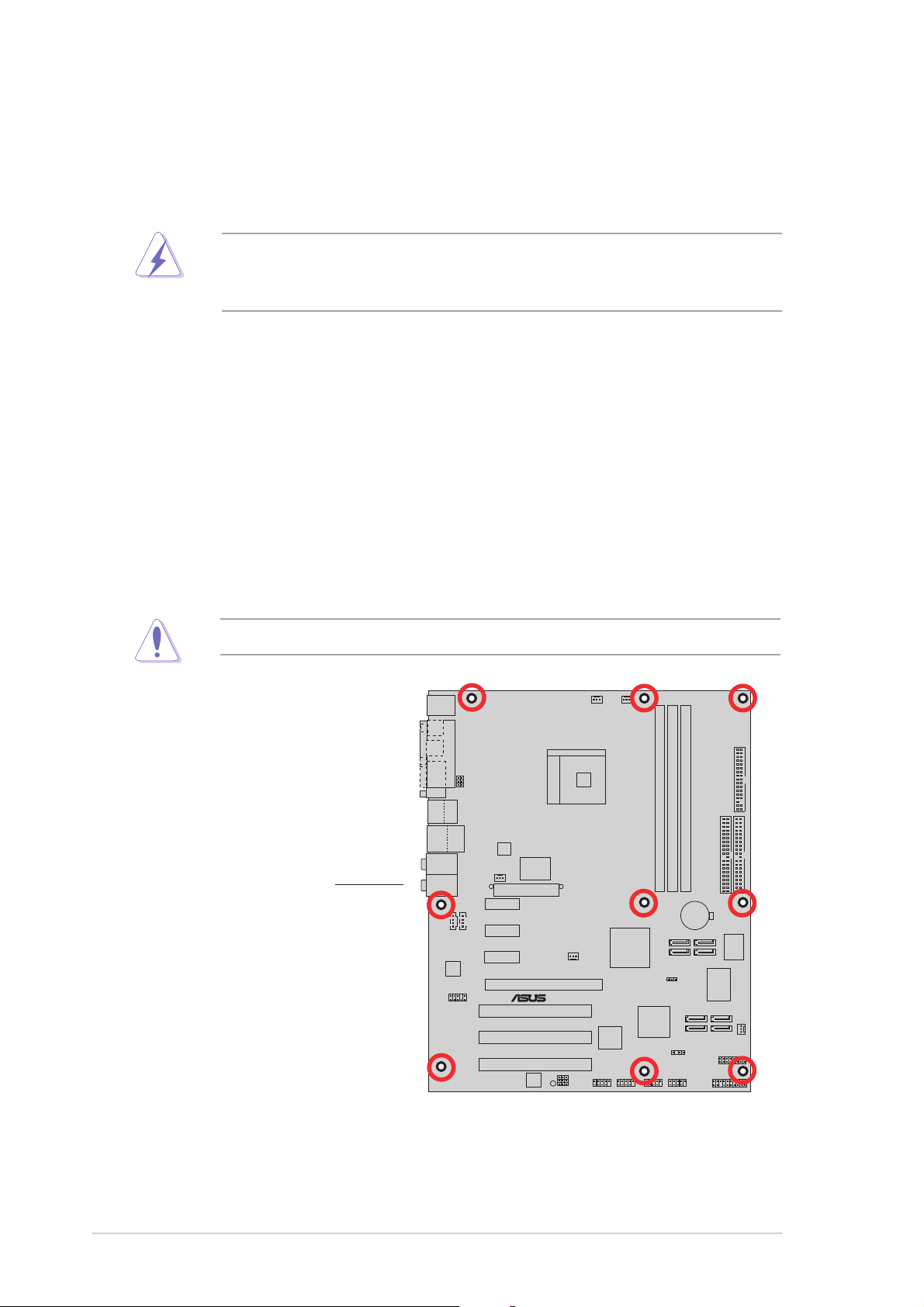
Screw holesScrew holes
Screw holes
Screw holesScrew holes
Place nine (9) screws into the holes indicated by circles to secure the
motherboard to the chassis.
Do not overtighten the screws! Doing so can damage the motherboard.
Place this side towardsPlace this side towards
Place this side towards
Place this side towardsPlace this side towards
the rear of the chassisthe rear of the chassis
the rear of the chassis
the rear of the chassisthe rear of the chassis
K8N4-E
2-22-2
2-2
2-22-2
Chapter 2: Hardware informationChapter 2: Hardware information
Chapter 2: Hardware information
Chapter 2: Hardware informationChapter 2: Hardware information
Page 27
2.2.32.2.3
®
24.5cm (9.6in)
2.2.3
2.2.32.2.3
PS/2KBMS
T: Mouse
B: Keyboard
SPDIF_O1
SPDIF_O2
PARALLEL PORT
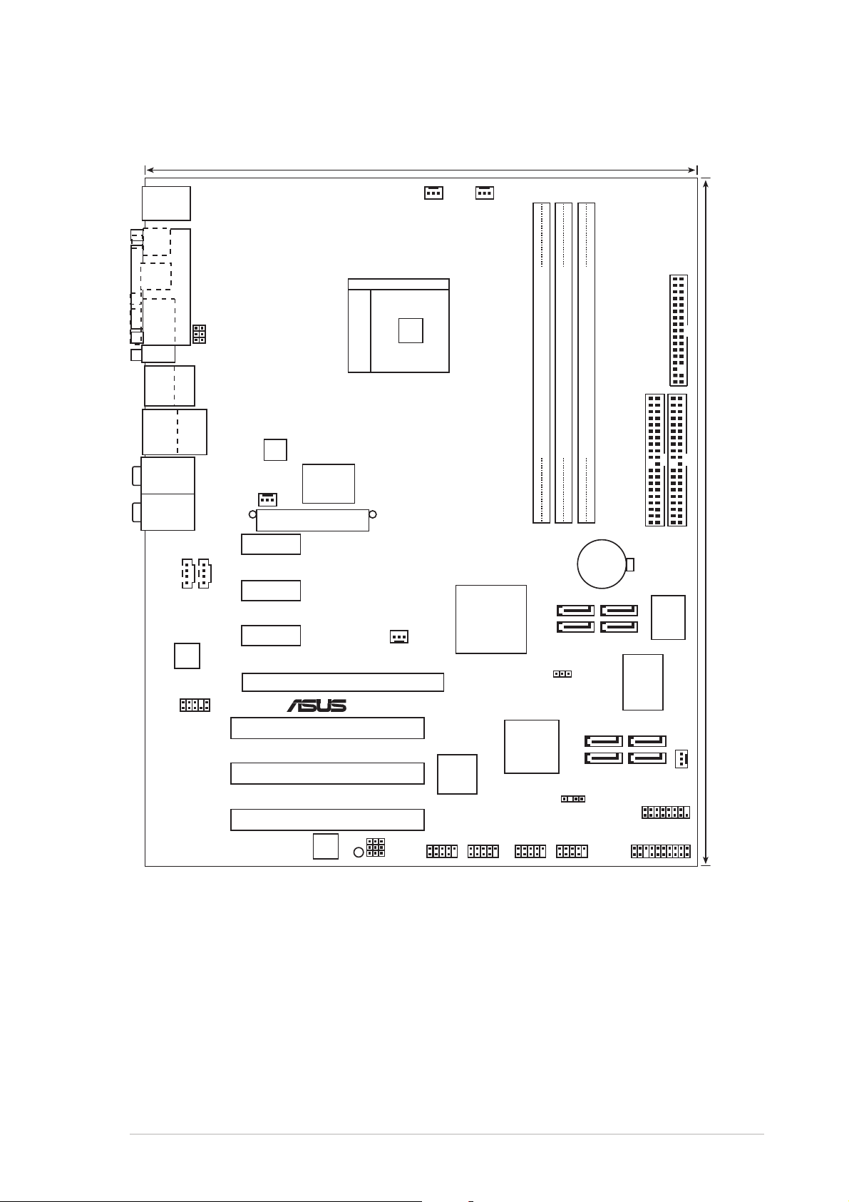
Motherboard layoutMotherboard layout
Motherboard layout
Motherboard layoutMotherboard layout
USBPW12
USBPW34
CPU_FAN
CHA2_FAN
COM1
USB2.0
Top:
T:USB1
1394
B:USB2
USB2.0
Top:
T: USB3
RJ-45
B: USB4
Top(gray):
Rear Surround L/R
Middle(black):
Side surround L/R
Bottom(y-orange):
Center/Subwoofer
Top:Line In
Center:Line Out
Below:Mic In
CD AUX
ALC850
FP_AUDIO
ATX12V
PWR_FAN
Marvell
Gbit LAN
88E1111
EATXPWR
PCIEX1_1
PCIEX1_2
PCIEX1_3
K8N4-E
PCIEX16
PCI1
PCI2
Socket 754
CHIP_FAN
nForce™4
TI
TSB43AB22A
NVIDIA
4X
DDR DIMM2 (64 bit,184-pin module)
DDR DIMM1 (64 bit,184-pin module)
®
Silicon Image
SATA
Controller
DDR DIMM3 (64 bit,184-pin module)
CR2032 3V
Lithium Cell
CMOS Power
SATA4
SATA2
CLRTC
SATA3
SATA1
SATA_RAID3
SATA_RAID1
SATA_RAID4
SATA_RAID2
FLOPPY
SEC_IDE
4Mbit
I/O
Super
PRI_IDE
BIOS
30.5cm (12.0in)
CHA1_FAN
CHASSIS
GAME
PCI3
Speech
Controller
SB_PWR
ASUS K8N4-E DeluxeASUS K8N4-E Deluxe
ASUS K8N4-E Deluxe
ASUS K8N4-E DeluxeASUS K8N4-E Deluxe
USBPW56
USBPW78
USBPW910
USB56
USB78 USB910 IE1394_2
PANEL
2-32-3
2-3
2-32-3
Page 28
2.2.42.2.4
2.2.4
2.2.42.2.4
Layout ContentsLayout Contents
Layout Contents
Layout ContentsLayout Contents
SlotsSlots
Slots
SlotsSlots
1. DDR DIMM slots 2-8
2. PCI slots 2-15
3. PCI Express slots 2-15
JumpersJumpers
Jumpers
JumpersJumpers
1. Clear RTC RAM (3-pin CLRTC1) 2-16
2. USB device wake-up (3-pin USBPW12, USBPW34, USBPW56, 2-17
USBPW78, USBPW910)
Rear panel connectorsRear panel connectors
Rear panel connectors
Rear panel connectorsRear panel connectors
1. PS/2 mouse port 2-18
2. Parallel port 2-18
3. IEEE 1394a port 2-18
4. LAN (RJ-45) port 2-18
5. Rear Speaker Out port 2-18
6. Side Speaker Out port 2-18
7. Line In port 2-18
8. Line Out port 2-18
9. Microphone port 2-19
10. Center/Subwoofer port 2-19
11. USB 2.0 ports 3 and 4 2-19
12. USB 2.0 ports 1 and 2 2-19
13. Serial (COM1) port 2-19
14. Optical S/PDIF Out port 2-19
15. Coaxial S/PDIF Out port 2-19
16. PS/2 keyboard port 2-19
PagePage
Page
PagePage
PagePage
Page
PagePage
PagePage
Page
PagePage
2-42-4
2-4
2-42-4
Chapter 2: Hardware informationChapter 2: Hardware information
Chapter 2: Hardware information
Chapter 2: Hardware informationChapter 2: Hardware information
Page 29

Internal connectorsInternal connectors
Internal connectors
Internal connectorsInternal connectors
1. Floppy disk drive connector (34-1 pin FLOPPY) 2-20
2. IDE connectors (40-1 pin PRI_IDE, SEC_IDE) 2-21
3. Serial ATA connectors (7-pin SATA1 [black], SATA2 [black], 2-22
SATA3 [black], SATA4 [black])
4. Serial ATA RAID connectors (7-pin SATA_RAID1 [red], 2-23
SATA_RAID2 [red], SATA_RAID3 [red], SATA_RAID4 [red])
5. CPU fan connector (3-pin CPU_FAN) 2-24
6. Chassis fan connectors (3-pin CHA1_FAN, 3-pin CHA2_FAN) 2-24
7. Chipset fan connector (3-pin CHIP_FAN) 2-24
8. Power fan connector (3-pin PWR_FAN) 2-24
9. USB connectors (10-1 pin USB56, USB78, USB910) 2-25
10. ATX power connectors (24-pin EATXPWR, 4-pin ATX12V) 2-26
11. Internal audio connectors (4-pin CD, AUX) 2-27
12. GAME/MIDI port connector (16-1 pin GAME) 2-27
13. Chassis intrusion connector (4-1 pin CHASSIS) 2-28
14. IEEE 1394a connector (10-1 pin IE1394_2) 2-28
15. Front panel audio connector (10-1 pin 2 x 5-pin FP_AUDIO) 2-29
16. System panel connector (20-pin PANEL) 2-30
- System Power LED (Green 3-pin PLED)
- Hard Disk activity (Red 2-pin IDE_LED)
- System warning speaker (Orange 4-pin SPEAKER)
- Power/Soft-off button(Yellow 2-pin PWRSW)
- Reset switch (Blue 2-pin RESET)
PagePage
Page
PagePage
ASUS K8N4-E DeluxeASUS K8N4-E Deluxe
ASUS K8N4-E Deluxe
ASUS K8N4-E DeluxeASUS K8N4-E Deluxe
2-52-5
2-5
2-52-5
Page 30
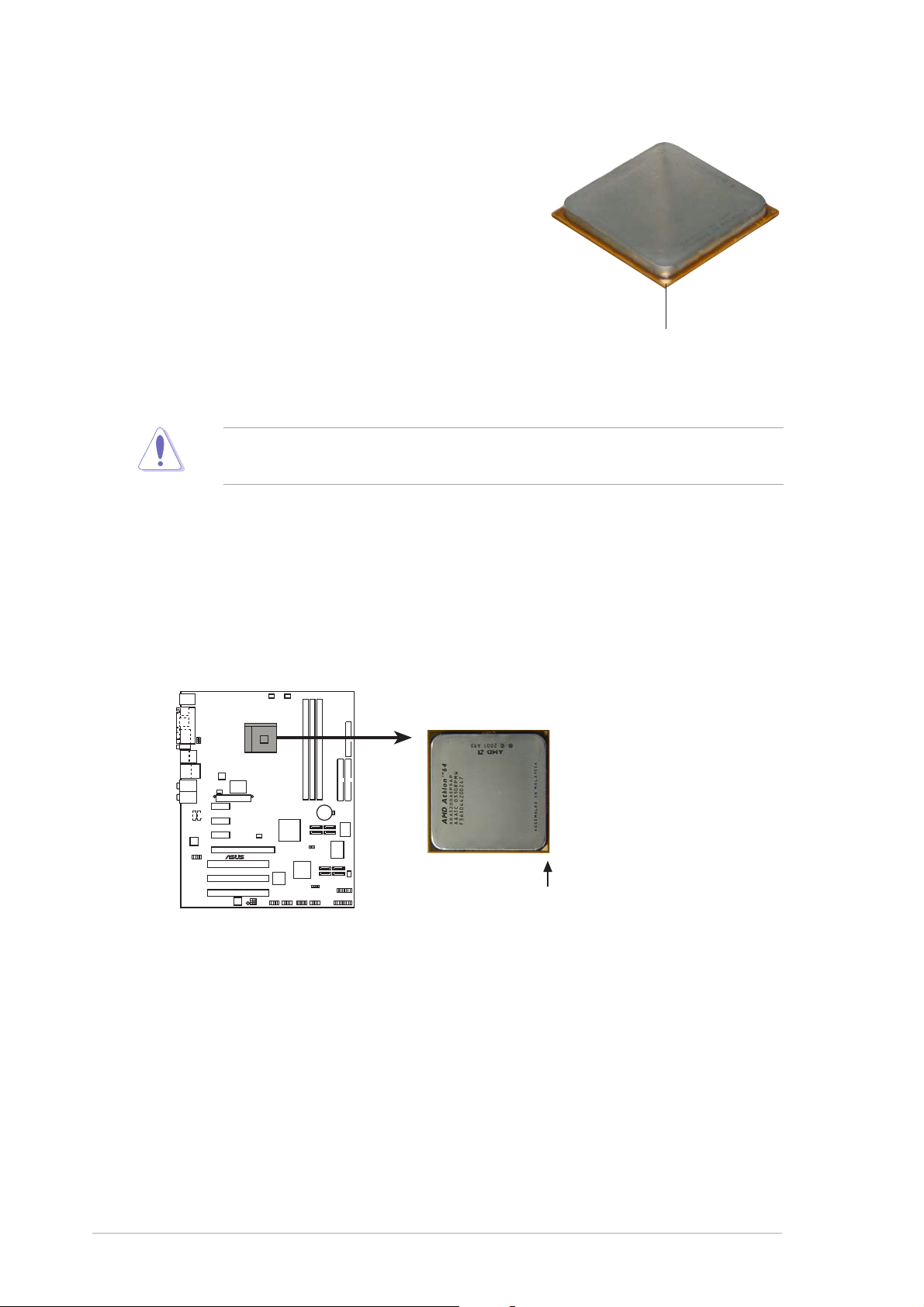
2.3 Central Processing Unit (CPU)
®
USB 2.0 connectors
w
The motherboard comes with a surface mount
754-pin Zero Insertion Force (ZIF) socket
designed for the AMD Athlon™ 64/AMD
Sempron™ processor.
Take note of the marked corner (with gold
triangle) on the CPU. This mark should match
a specific corner on the socket to ensure
correct installation.
Gold triangleGold triangle
Gold triangle
Gold triangleGold triangle
Incorrect installation of the CPU into the socket may bend the pins and
severely damage the CPU!
Installing the CPUInstalling the CPU
Installing the CPU
Installing the CPUInstalling the CPU
To install a CPU:
1. Locate the 754-pin ZIF socket on the motherboard.
K8N4-E
Gold Arro
K8N4-E DELUXE Socket 754
2-62-6
2-6
2-62-6
Chapter 2: Hardware informationChapter 2: Hardware information
Chapter 2: Hardware information
Chapter 2: Hardware informationChapter 2: Hardware information
Page 31

2. Unlock the socket by pressing
the lever sideways, then lift it up
to a 90°-100° angle.
Make sure that the socket
lever is lifted up to 90°-100°
angle; otherwise the CPU does
not fit in completely.
3. Position the CPU above the
socket such that the CPU corner
with the gold triangle matches
the socket corner with a small
triangle.
SocketSocket
Socket
SocketSocket
leverlever
lever
leverlever
4. Carefully insert the CPU into the
socket until it fits in place.
GoldGold
Gold
GoldGold
triangletriangle
triangle
triangletriangle
5. When the CPU is in place, push
down the socket lever to secure
the CPU. The lever clicks on the
side tab to indicate that it is
locked.
6. Install a CPU heatsink and fan
following the instructions that
came with the heatsink package.
7. Connect the CPU fan cable to the
CPU_FAN connector on the
motherboard.
ASUS K8N4-E DeluxeASUS K8N4-E Deluxe
ASUS K8N4-E Deluxe
ASUS K8N4-E DeluxeASUS K8N4-E Deluxe
2-72-7
2-7
2-72-7
Page 32
2.4 System memory
®
3
2.4.12.4.1
2.4.1
2.4.12.4.1
OverviewOverview
Overview
OverviewOverview
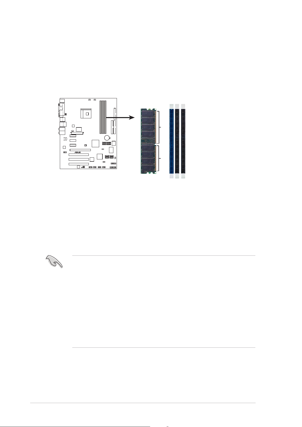
The motherboard comes with three 184-pin Double Data Rate (DDR) Dual
Inline Memory Modules (DIMM) sockets.
The following figure illustrates the location of the sockets:
DIMM1DIMM2DIMM
K8N4-E
80 Pins 104 Pins
K8N4-E DELUXE
184-pin DDR DIMM sockets
2.4.22.4.2
2.4.2
2.4.22.4.2
Memory ConfigurationsMemory Configurations
Memory Configurations
Memory ConfigurationsMemory Configurations
You may install 256 MB, 512 MB, and 1 GB unbuffered non-ECC DDR DIMMs
into the DIMM sockets using the memory configurations in this section.
•
Installing DDR DIMMs other than the recommended configurations
may cause memory sizing error or system boot failure. Use any of
the recommended configurations on the next page.
•
Always install DIMMs with the same CAS latency. For optimum
compatibility, we recommend that you obtain memory modules from
the same vendor.
• Due to chipset resource allocation, the system may detect less than
3 GB system memory when you installed three 1 GB DDR memory
modules.
• This motherboard does not support memory modules made up of
128 Mb chips or double sided x16 memory modules.
2-82-8
2-8
2-82-8
Chapter 2: Hardware informationChapter 2: Hardware information
Chapter 2: Hardware information
Chapter 2: Hardware informationChapter 2: Hardware information
Page 33

Recommended DDR memory configurationsRecommended DDR memory configurations
Recommended DDR memory configurations
Recommended DDR memory configurationsRecommended DDR memory configurations
DIMM slotDIMM slot
DIMM slot
DIMM slotDIMM slot
NumberNumber
Number
NumberNumber
of DIMMsof DIMMs
of DIMMs
of DIMMsof DIMMs
1 Single side – – DDR 400
1 – Single side – DDR 400
1 – – Single side DDR 400
1 Double side – – DDR 400
1 – Double side – DDR 400
1 – – Double side DDR 400
2 Single side Single side – DDR 400
2 Single side Double side – DDR 400
2 Single side – Single side DDR 400
2 Single side – Double side DDR 400
2 Double side Single side – DDR 400
2 Double side Double side – DDR 400
2 Double side – Single side DDR 400
DIMM1DIMM1
DIMM1
DIMM1DIMM1
DIMM2DIMM2
DIMM2
DIMM2DIMM2
DIMM3DIMM3
DIMM3
DIMM3DIMM3
Max SpeedMax Speed
Max Speed
Max SpeedMax Speed
2 – Single side Single side DDR 333
2 – Single side Double side DDR 200
2 – Double side Single side DDR 200
2 – Double side Double side DDR 200
2 Double side – Double side DDR 400
3 Single side Single side Single side DDR 333
3 Single side Single side Double side DDR 200
3 Single side Double side Single side DDR 200
3 Single side Double side Double side DDR 200
3 Double side Single side Single side DDR 333
3 Double side Single side Double side DDR 200
3 Double side Double side Single side DDR 200
3 Double side Double side Double side DDR 200
ASUS K8N4-E DeluxeASUS K8N4-E Deluxe
ASUS K8N4-E Deluxe
ASUS K8N4-E DeluxeASUS K8N4-E Deluxe
2-92-9
2-9
2-92-9
Page 34

DDR (400 MHz) Qualified Vendors ListDDR (400 MHz) Qualified Vendors List
DDR (400 MHz) Qualified Vendors List
DDR (400 MHz) Qualified Vendors ListDDR (400 MHz) Qualified Vendors List
DIMM supportDIMM support
DIMM support
DIMM supportDIMM support
SizeSize
Size
SizeSize
256MB KINGSTON KVR400X64C3A/256 Hynix SS HY5DU56822BT-D43 –
512MB KINGSTON KVR400X64C3A/512 Hynix DS HY5DU56822BT-D43 –
256MB KINGSTON KVR400X72C3A/256 Mosel SS V58C2256804SAT5(ECC) –
512MB KINGSTON KVR400X72C3A/512 Mosel DS V58C2256804SAT5(ECC) –
256MB KINGSTON KVR400X64C3A/256 Infineon SS HYB25D256800BT-5B –
512MB KINGSTON KVR400X64C3A/512 Infineon DS HYB25D256809BT-5B –
256MB KINGSTON KVR400X64C3A/256 KINGSTON SS D3208DL2T-5 –
512MB KINGSTON KHX3200A/512 – DS – 3
1024MB KINGSTON KVR400X64C3A/1G – DS HYB25D512800BE-5B 3
1024MB KINGSTON KHX3200ULK2/1G – DS – 2
256MB SAMSUNG M381L3223ETM-CCC SAMSUNG SS K4H560838E-TCCC(ECC) 3ECC
512MB SAMSUNG M381L6423ETM-CCC SAMSUNG DS K4H560838E-TCCC(ECC) –
256MB SAMSUNG M368L3223ETM-CCC SAMSUNG SS K4H560838E-TCCC –
256MB SAMSUNG M368L3223FTN-CCC SAMSUNG SS K4H560838F-TCCC 4
512MB SAMSUNG M368L6423FTN-CCC SAMSUNG DS K4H560838F-TCCC 4
512MB SAMSUNG M368L6523BTM-CCC SAMSUNG SS K4H510838B-TCCC 4
256MB MICRON MT8VDDT3264AG-40BCB MICRON SS MT46V32M8TG-5BC –
512MB MICRON MT16VDDT6464AG-40BCB MICRON DS MT46V32M8TG-5BC –
256MB Infineon HYS64D32300HU-5-C Infineon SS HYB25D256800CE-5C 3
512MB Infineon HYS64D64320HU-5-C Infineon DS HYB25D256800CE-5C –
256MB CORSAIR CMX256A-3200C2PT Winbond SS W942508BH-5 2
512MB CORSAIR VS512MB400 VALUE seLecT DS VS32M8-5 2.5
512MB CORSAIR CMX512-3200C2 – DS – 3
1024MB CORSAIR TWINX2048-3200C2 – DS – –
256MB Hynix HYMD232645D8J-D43 Hynix SS HY5DU56822DT-D43 3
512MB Hynix HYMD264646D8J-D43 Hynix DS HY5DU56822DT-D43 3
256MB TwinMOS M2G9I08AIATT9F081AADT TwinMOS SS TMD7608F8E50D 2.5
512MB TwinMOS M2G9J16AJATT9F081AADT TwinMOS DS TMD7608F8E50D 2.5
256MB TwinMOS M2G9I08A8ATT9F081AADT TwinMOS SS TMD7608F8E50D 2.5
512MB TwinMOS M2G9J16A8ATT9F081AADT TwinMOS DS TMD7608F8E50D 2.5
256MB Transcend TS32MLD64V4F3 SAMSUNG SS K4H560838F-TCCC 3
512MB Transcend TS64MLD64V4F3 SAMSUNG DS K4H560838F-TCCC 3
1024MB Transcend TS128MLD64V4J SAMSUNG DS K4H510838B-TCCC 3
256MB Apacer 77.10636.33G Infineon SS HYB25D256800CE-5C 3
512MB Apacer 77.10736.33G Infineon DS HYB25D256800CE-5C 3
256MB Apacer 77.10639.60G ProMOS SS V58C2256804SCT5B 2.5
512MB Apacer 77.10739.60G ProMOS DS V58C2256804SCT5B 2.5
256MB A DATA MDOSS6F3G31Y0K1E0Z SAMSUNG SS K4H560838E-TCCC 3
512MB A DATA MDOSS6F3H41Y0N1E0Z SAMSUNG DS K4H560838F-TCCC 3
256MB A DATA MDOHY6F3G31Y0N1E0Z Hynix SS HY5DU56822CT-D43 3
512MB A DATA MDOHY6F3H41Y0N1E0Z Hynix DS HY5DU56822CT-D43 3
256MB A DATA MDOAD5F3G31Y0D1E02 – SS ADD8608A8A-5B 2.5
512MB A DATA MDOAD5F3H41Y0D1E02 – DS ADD8608A8A-5B 2.5
256MB Winbond W9425GCDB-5 Winbond SS W942508CH-5 3
512MB Winbond W9451GCDB-5 Winbond DS W942508CH-5 –
256MB PSC AL5D8B53T-5B1K PSC SS A2S56D30BTP 2.5
VendorVendor
Vendor
VendorVendor
ModelModel
Model
ModelModel
BrandBrand
Brand
BrandBrand
Side/s*Side/s*
Side/s*
Side/s*Side/s*
ComponentComponent
Component
ComponentComponent
CLCL
CL
CLCL
2-102-10
2-10
2-102-10
Chapter 2: Hardware informationChapter 2: Hardware information
Chapter 2: Hardware information
Chapter 2: Hardware informationChapter 2: Hardware information
Page 35

DDR (400 MHz) Qualified Vendors ListDDR (400 MHz) Qualified Vendors List
DDR (400 MHz) Qualified Vendors List
DDR (400 MHz) Qualified Vendors ListDDR (400 MHz) Qualified Vendors List
DIMM support DIMM support
DIMM support
DIMM support DIMM support
SizeSize
Size
SizeSize
512MB PSC AL6D8B53T-5B1K PSC DS A2S56D30BTP 2.5
256MB KINGMAX MPXB62D-38KT3R – SS KDL388P4LA-50 –
512MB KINGMAX MPXC22D-38KT3R – DS KDL388P4LA-50 –
256MB NANYA NT256D64S88C0G-5T – SS NT5DS32M8CT-5T 3
512MB NANYA NT512D64S8HC0G-5T – DS NT5DS32M8CT-5T 3
256MB BRAIN POWER B6U808-256M-SAM-400 SAMSUNG SS K4H560838D-TCC4 –
512MB BRAIN POWER B6U808-512M-SAM-400 SAMSUNG DS K4H560838D-TCC4 –
256MB CENTURY DXV6S8SSCCE3K27E SAMSUNG SS K4H560838E-TCCC –
512MB CENTURY DXV2S8SSCCE3K27E SAMSUNG DS K4H560838E-TCCC –
256MB CENTURY DXV6S8EL5BM3T27C – SS DD2508AMTA –
512MB CENTURY DXV2S8EL5BM3T27C – DS DD2508AMTA –
256MB elixir M2U25664DS88C3G-5T – SS N2DS25680CT-5T –
512MB elixir M2U51264DS8HC1G-5T – DS N2DS25680CT-5T –
256MB Kreton – VT SS VT3225804T-5 –
512MB Kreton – VT DS VT3225804T-5 –
256MB Veritech VT400FMV/2561103 VT SS VT56DD32M8PC-5 3
512MB Veritech VT400FMV/5121003 VT DS VT56DD32M8PC-5 3
256MB Pmi MD44256VIT3208GMHA01 MOSEL SS V58C2256804SAT5B 2.5
512MB Pmi MD44512VIT3208GATA03 MOSEL DS V58C2256804SAT5B 2.5
256MB ProMOS V826632K24SCTG-D0 – SS V58C2256804SCT5B 2.5
512MB ProMOS V826664K24SCTG-D0 – DS V58C2256804SCT5B 2.5
256MB Deutron AL5D8C53T-5B1T PSC SS A2S56D30CTP 2.5
512MB Deutron AL6D8C53T-5B1T PSC DS A2S56D30CTP 2.5
256MB GEIL GL5123200DC – SS GL3LC32G88TG-35 –
512MB GEIL GL1GB3200DC – DS GL3LC32G88TG-35 –
256MB GEIL GLX2563200UP – SS GL3LC32G88TG-5A –
256MB GEIL GD3200-512DC – SS WLCSP Package –
256MB crucial BL3264Z402.8TG Ballistix SS – 2
512MB crucial BL6464Z402.16TG Ballistix DS – 2
256MB Novax 96M425653CE-40TB6 CEON SS C2S56D30TP-5 2.5
512MB Novax 96M451253CE-40TB6 CEON DS C2S56D30TP-5 2.5
VendorVendor
Vendor
VendorVendor
ModelModel
Model
ModelModel
BrandBrand
Brand
BrandBrand
Side/s*Side/s*
Side/s*
Side/s*Side/s*
ComponentComponent
Component
ComponentComponent
CLCL
CL
CLCL
Legend:Legend:
Legend:
Legend:Legend:
SSSS
S S - Single-sided
SSSS
DSDS
D S - Double-sided
DSDS
CLCL
C L - CAS Latency
CLCL
Visit the ASUS website (www.asus.com) for the latest DDR 400 Qualified
Vendors List.
ASUS K8N4-E DeluxeASUS K8N4-E Deluxe
ASUS K8N4-E Deluxe
ASUS K8N4-E DeluxeASUS K8N4-E Deluxe
2-112-11
2-11
2-112-11
Page 36

2.4.32.4.3
2.4.3
2.4.32.4.3
Installing a DDR DIMMInstalling a DDR DIMM
Installing a DDR DIMM
Installing a DDR DIMMInstalling a DDR DIMM
Make sure to unplug the power supply before adding or removing DIMMs
or other system components. Failure to do so may cause severe damage
to both the motherboard and the components.
1. Unlock a DIMM socket by
pressing the retaining clips
outward.
2. Align a DIMM on the socket such
that the notch on the DIMM
matches the break on the
socket.
2
DDR DIMM notchDDR DIMM notch
DDR DIMM notch
DDR DIMM notchDDR DIMM notch
1
1
Unlocked retaining clipUnlocked retaining clip
Unlocked retaining clip
Unlocked retaining clipUnlocked retaining clip
A DDR DIMM is keyed with a notch so that it fits in only one direction.
DO NOT force a DIMM into a socket to avoid damaging the DIMM.
3. Firmly insert the DIMM into the
socket until the retaining clips
snap back in place and the DIMM
is properly seated.
2.4.42.4.4
2.4.4
2.4.42.4.4
Removing a DDR DIMMRemoving a DDR DIMM
Removing a DDR DIMM
Removing a DDR DIMMRemoving a DDR DIMM
To remove a DIMM:
1. Simultaneously press the
retaining clips outward to unlock
the DIMM.
Locked Retaining ClipLocked Retaining Clip
Locked Retaining Clip
Locked Retaining ClipLocked Retaining Clip
2
1
Support the DIMM lightly with your fingers when pressing the retaining
clips. The DIMM might get damaged when it flips out with extra force.
2. Remove the DIMM from the socket.
2-122-12
2-12
2-122-12
1
Chapter 2: Hardware informationChapter 2: Hardware information
Chapter 2: Hardware information
Chapter 2: Hardware informationChapter 2: Hardware information
DDR DIMM notchDDR DIMM notch
DDR DIMM notch
DDR DIMM notchDDR DIMM notch
Page 37

2.5 Expansion slots
In the future, you may need to install expansion cards. The following
sub-sections describe the slots and the expansion cards that they support.
Make sure to unplug the power cord before adding or removing
expansion cards. Failure to do so may cause you physical injury and
damage motherboard components.
2.5.12.5.1
2.5.1
2.5.12.5.1
To install an expansion card:
1. Before installing the expansion card, read the documentation that
came with it and make the necessary hardware settings for the card.
2. Remove the system unit cover (if your motherboard is already
installed in a chassis).
3. Remove the bracket opposite the slot that you intend to use. Keep
the screw for later use.
4. Align the card connector with the slot and press firmly until the card is
completely seated on the slot.
5. Secure the card to the chassis with the screw you removed earlier.
6. Replace the system cover.
2.5.22.5.2
2.5.2
2.5.22.5.2
After installing the expansion card, configure it by adjusting the software
settings.
Installing an expansion cardInstalling an expansion card
Installing an expansion card
Installing an expansion cardInstalling an expansion card
Configuring an expansion cardConfiguring an expansion card
Configuring an expansion card
Configuring an expansion cardConfiguring an expansion card
1. Turn on the system and change the necessary BIOS settings, if any.
See Chapter 4 for information on BIOS setup.
2. Assign an IRQ to the card. Refer to the tables on the next page.
3. Install the software drivers for the expansion card.
ASUS K8N4-E DeluxeASUS K8N4-E Deluxe
ASUS K8N4-E Deluxe
ASUS K8N4-E DeluxeASUS K8N4-E Deluxe
2-132-13
2-13
2-132-13
Page 38
2.5.32.5.3
2.5.3
2.5.32.5.3
Standard interrupt assignmentsStandard interrupt assignments
Standard interrupt assignments
Standard interrupt assignmentsStandard interrupt assignments
Interrupt assignmentsInterrupt assignments
Interrupt assignments
Interrupt assignmentsInterrupt assignments
IRQIRQ
IRQ
IRQIRQ
0 1 System Timer
1 2 Keyboard Controller
2 — Programmable Interrupt
3* 11 IRQ holder for PCI steering
4* 12 Communications Port (COM1)
5* 13 IRQ holder for PCI steering
6 14 Floppy Disk Controller
7* 15 Printer Port (LPT1)
8 3 System CMOS/Real Time Clock
9* 4 IRQ holder for PCI steering
10* 5 IRQ holder for PCI steering
11* 6 IRQ holder for PCI steering
12* 7 PS/2 Compatible Mouse Port
13 8 Numeric Data Processor
14* 9 Primary IDE Channel
15* 10 Secondary IDE Channel
* These IRQs are usually available for ISA or PCI devices.* These IRQs are usually available for ISA or PCI devices.
* These IRQs are usually available for ISA or PCI devices.
* These IRQs are usually available for ISA or PCI devices.* These IRQs are usually available for ISA or PCI devices.
IRQ assignments for this motherboardIRQ assignments for this motherboard
IRQ assignments for this motherboard
IRQ assignments for this motherboardIRQ assignments for this motherboard
PriorityPriority
Priority
PriorityPriority
Standard FunctionStandard Function
Standard Function
Standard FunctionStandard Function
AA
A
AA
PCI slot 1 shared — — — — — — —
PCI slot 2 — shared — — — — — —
PCI slot 3 — — shared — — — — —
Onboard USB 2.0 controller shared — — — — — — —
Onboard LAN1 shared — — — — — — —
Onboard PCI SATA RAID (SI) — — — shared — — — —
Onboard 1394a shared — — — — — — —
BB
B
BB
CC
C
CC
DD
D
DD
EE
E
EE
FF
F
FF
GG
G
GG
HH
H
HH
When using PCI cards on shared slots, ensure that the drivers support
“Share IRQ” or that the cards do not need IRQ assignments. Otherwise,
conflicts will arise between the two PCI groups, making the system
unstable and the card inoperable.
2-142-14
2-14
2-142-14
Chapter 2: Hardware informationChapter 2: Hardware information
Chapter 2: Hardware information
Chapter 2: Hardware informationChapter 2: Hardware information
Page 39
2.5.42.5.4
2.5.4
2.5.42.5.4
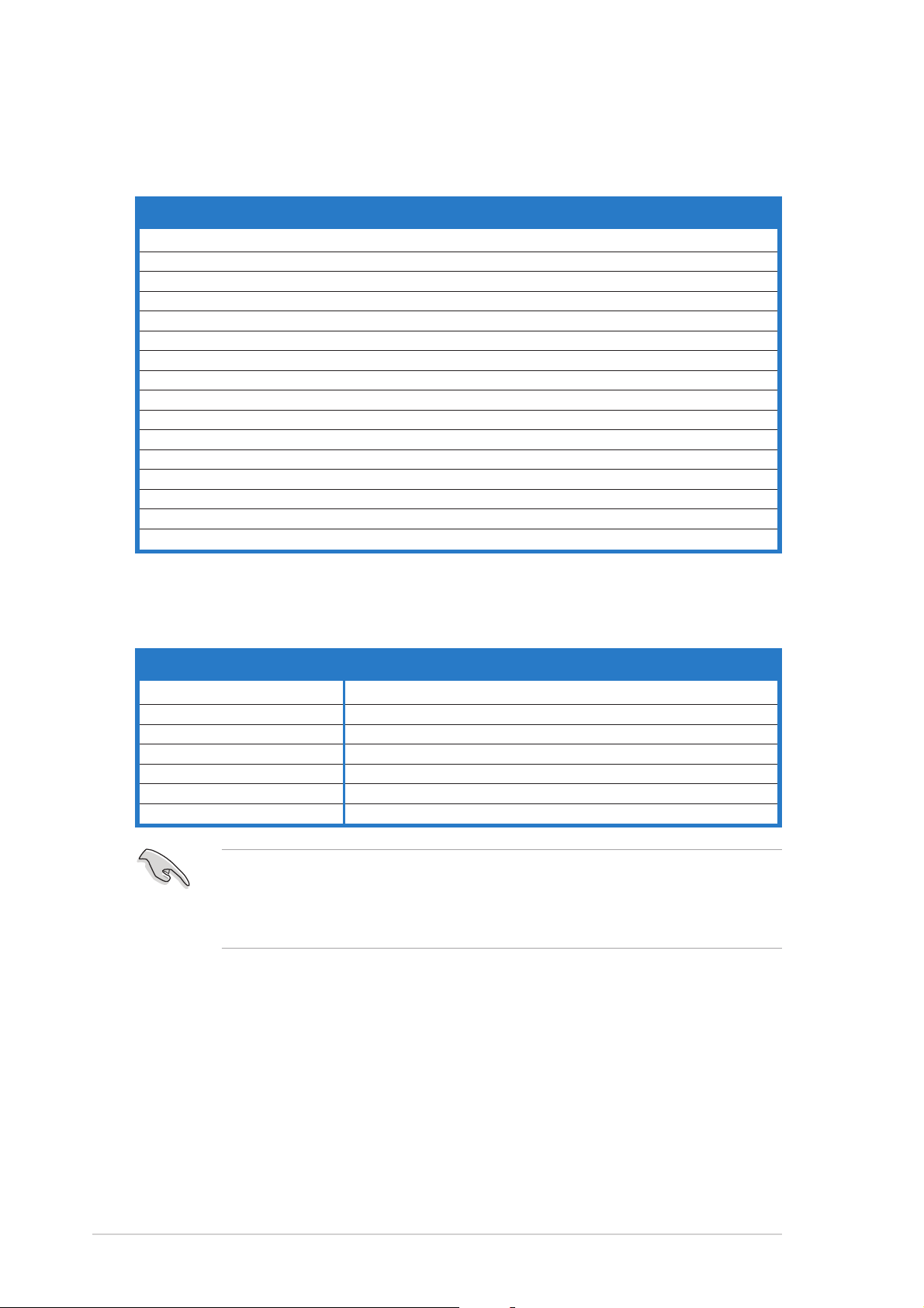
The PCI slots support cards such as a
LAN card, SCSI card, USB card, and
other cards that comply with PCI
specifications. The figure shows a
LAN card installed on a PCI slot.
PCI slotsPCI slots
PCI slots
PCI slotsPCI slots
2.5.52.5.5
2.5.5
2.5.52.5.5
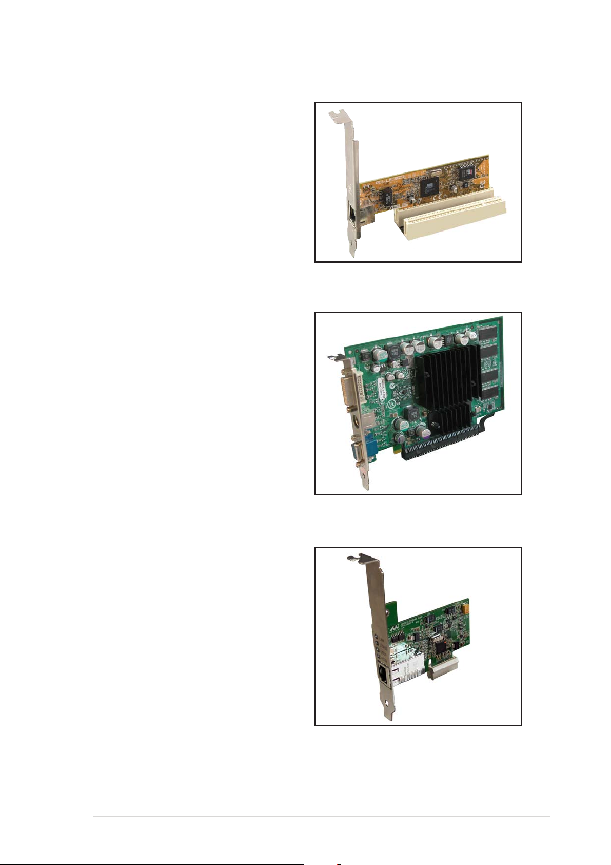
This motherboard supports PCI
Express x16 graphic cards that
comply with the PCI Express
specifications. The following figure
shows a graphics card installed on
the PCI Express x16 slot.
2.5.62.5.6
2.5.6
2.5.62.5.6
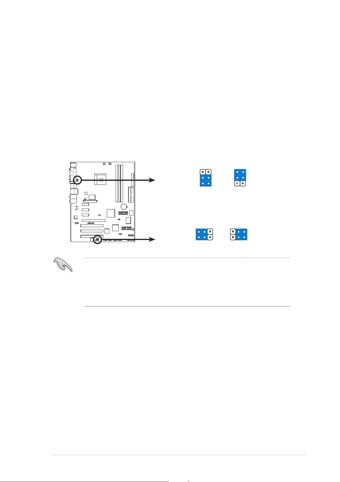
This motherboard supports PCI
Express x1 network cards, SCSI cards,
and other cards that comply with the
PCI Express specifications. The
following figure shows a network card
installed on the PCI Express x1 slot.
PCI Express x16 slotPCI Express x16 slot
PCI Express x16 slot
PCI Express x16 slotPCI Express x16 slot
PCI Express x1 slotPCI Express x1 slot
PCI Express x1 slot
PCI Express x1 slotPCI Express x1 slot
ASUS K8N4-E DeluxeASUS K8N4-E Deluxe
ASUS K8N4-E Deluxe
ASUS K8N4-E DeluxeASUS K8N4-E Deluxe
2-152-15
2-15
2-152-15
Page 40

2.6 Jumpers
®
S
1.1.
Clear RTC RAM (CLRTC)Clear RTC RAM (CLRTC)
1.
Clear RTC RAM (CLRTC)
1.1.
Clear RTC RAM (CLRTC)Clear RTC RAM (CLRTC)
This jumper allows you to clear the Real Time Clock (RTC) RAM in
CMOS. You can clear the CMOS memory of date, time, and system
setup parameters by erasing the CMOS RTC RAM data. The onboard
button cell battery powers the RAM data in CMOS, which include
system setup information such as system passwords.
To erase the RTC RAM:
1. Turn OFF the computer and unplug the power cord.
2. Remove the onboard battery.
3. Move the jumper cap from pins 1-2 (default) to pins 2-3. Keep the
cap on pins 2-3 for about 5~10 seconds, then move the cap back to
pins 1-2.
4. Re-install the battery.
5. Plug the power cord and turn ON the computer.
6. Hold down the <Del> key during the boot process and enter BIOS
setup to re-enter data.
Except when clearing the RTC RAM, never remove the cap on CLRTC
jumper default position. Removing the cap will cause system boot failure!
CLRTC
K8N4-E
K8N4-E DELUXE Clear RTC RAM
You do not need to clear the RTC when the system hangs due to
overclocking. For system failure due to overclocking, use the C.P.R. (CPU
Parameter Recall) feature. Shut down and reboot the system so the BIOS
can automatically reset parameter settings to default values.
21 3
Normal Clear CMO
(Default)
2
2-162-16
2-16
2-162-16
Chapter 2: Hardware informationChapter 2: Hardware information
Chapter 2: Hardware information
Chapter 2: Hardware informationChapter 2: Hardware information
Page 41
2.2.
®
USBPW12
USB device wake-up (3-pin USBPW12, USBPW34,USB device wake-up (3-pin USBPW12, USBPW34,
2.
USB device wake-up (3-pin USBPW12, USBPW34,
2.2.
USB device wake-up (3-pin USBPW12, USBPW34,USB device wake-up (3-pin USBPW12, USBPW34,
USBPW56, USBPW78, USBPW910)USBPW56, USBPW78, USBPW910)
USBPW56, USBPW78, USBPW910)
USBPW56, USBPW78, USBPW910)USBPW56, USBPW78, USBPW910)
Set these jumpers to +5V to wake up the computer from S1 sleep
mode (CPU stopped, DRAM refreshed, system running in low power
mode) using the connected USB devices. Set to +5VSB to wake up
from S3 and S4 sleep modes (no power to CPU, DRAM in slow refresh,
power supply in reduced power mode).
The USBPWR12 and USBPWR34 jumpers are for the rear USB ports.
The USBPWR56, USBPWR78, and USBPW910 jumpers are for the
internal USB connectors that you can connect to additional USB ports.
USBPW34
3
2
+5VSB
2
3
K8N4-E
2
1
+5V
(Default)
USBPW56
USBPW78
USBPW910
21
K8N4-E DELUXE USB device wake up
+5V
(Default)
+5VSB
• The USB device wake-up feature requires a power supply that can
provide 500mA on the +5VSB lead for each USB port; otherwise,
the system would not power up.
• The total current consumed must NOT exceed the power supply
capability (+5VSB) whether under normal condition or in sleep mode.
ASUS K8N4-E DeluxeASUS K8N4-E Deluxe
ASUS K8N4-E Deluxe
ASUS K8N4-E DeluxeASUS K8N4-E Deluxe
2-172-17
2-17
2-172-17
Page 42

2.7 Connectors
1
2 4
56
3
2.7.12.7.1
2.7.1
2.7.12.7.1
16 11
1.1.
PS/2 mouse port (green).PS/2 mouse port (green).
1.
PS/2 mouse port (green). This port is for a PS/2 mouse.
1.1.
PS/2 mouse port (green).PS/2 mouse port (green).
2.2.
Parallel port.Parallel port.
2.
Parallel port. This 25-pin port connects a parallel printer, a scanner,
2.2.
Parallel port.Parallel port.
Rear panel connectorsRear panel connectors
Rear panel connectors
Rear panel connectorsRear panel connectors
14
1315
12
10
or other devices.
3.3.
IEEE 1394a port.IEEE 1394a port.
3.
IEEE 1394a port. This 6-pin IEEE 1394a port provides high-speed
3.3.
IEEE 1394a port.IEEE 1394a port.
connectivity for audio/video devices, storage peripherals, PCs, or
portable devices.
7
8
9
4.4.
LAN (RJ-45) port.LAN (RJ-45) port.
4.
LAN (RJ-45) port. This port allows Gigabit connection to a Local
4.4.
LAN (RJ-45) port.LAN (RJ-45) port.
Area Network (LAN) through a network hub. Refer to the table below
for the LAN port LED indications.
LAN port LED indicationsLAN port LED indications
LAN port LED indications
LAN port LED indicationsLAN port LED indications
ACT/LINKACT/LINK
ACT/LINK
ACT/LINK LEDACT/LINK LED
ACT/LINK LED
ACT/LINK LEDACT/LINK LED
StatusStatus
Status
StatusStatus
OFF No link OFF 10Mbps connection
GREEN Linked ORANGE 100Mbps connection
BLINKING Acting GREEN 1Gbps connection
5.5.
Rear Speaker Out port (gray).Rear Speaker Out port (gray).
5.
Rear Speaker Out port (gray). This port connects the rear
5.5.
Rear Speaker Out port (gray).Rear Speaker Out port (gray).
DescriptionDescription
Description
DescriptionDescription
SPEED LED SPEED LED
SPEED LED
SPEED LED SPEED LED
StatusStatus
Status
StatusStatus
DescriptionDescription
Description
DescriptionDescription
ACT/LINKACT/LINK
LEDLED
LED
LEDLED
LAN portLAN port
LAN port
LAN portLAN port
SPEEDSPEED
SPEED
SPEEDSPEED
LEDLED
LED
LEDLED
speakers on a 4-channel, 6-channel, or 8-channel audio configuration.
6.6.
Side Speaker Out port (black).Side Speaker Out port (black).
6.
Side Speaker Out port (black). This port connects the side
6.6.
Side Speaker Out port (black).Side Speaker Out port (black).
speakers in an 8-channel audio configuration.
7.7.
Line In port (light blue).Line In port (light blue).
7.
Line In port (light blue). This port connects a tape, CD, DVD
7.7.
Line In port (light blue).Line In port (light blue).
player, or other audio sources.
2-182-18
2-18
2-182-18
8.8.
Line Out port (lime).Line Out port (lime).
8.
Line Out port (lime). This port connects a headphone or a
8.8.
Line Out port (lime).Line Out port (lime).
speaker. In 4-channel, 6-channel, and 8-channel configuration, the
function of this port becomes Front Speaker Out.
Chapter 2: Hardware informationChapter 2: Hardware information
Chapter 2: Hardware information
Chapter 2: Hardware informationChapter 2: Hardware information
Page 43

9.9.
Microphone port (pink). Microphone port (pink).
9.
Microphone port (pink). This port connects a microphone.
9.9.
Microphone port (pink). Microphone port (pink).
10.10.
Center/Subwoofer port (yellow orange).Center/Subwoofer port (yellow orange).
10.
Center/Subwoofer port (yellow orange). This port connects
10.10.
Center/Subwoofer port (yellow orange).Center/Subwoofer port (yellow orange).
the center/subwoofer speakers.
Refer to the audio configuration table for the function of the audio ports
in 2, 4, 6, or 8-channel configuration.
Audio 2, 4, 6, or 8-channel configurationAudio 2, 4, 6, or 8-channel configuration
Audio 2, 4, 6, or 8-channel configuration
Audio 2, 4, 6, or 8-channel configurationAudio 2, 4, 6, or 8-channel configuration
PortPort
Port
PortPort
Light Blue Line In Line In Line In Line In
Lime Line Out Front Speaker Out Front Speaker Out Front Speaker Out
Pink Mic In Mic In Mic In Mic In
Gray - Rear Speaker Out Rear Speaker Out Rear Speaker Out
Black - - - Side Speaker Out
Yellow Orange - - Center/Subwoofer Center/Subwoofer
11.11.
USB 2.0 ports 3 and 4.USB 2.0 ports 3 and 4.
11.
USB 2.0 ports 3 and 4. These two 4-pin Universal Serial Bus
11.11.
USB 2.0 ports 3 and 4.USB 2.0 ports 3 and 4.
HeadsetHeadset
Headset
HeadsetHeadset
2-channel2-channel
2-channel
2-channel2-channel
4-channel4-channel
4-channel
4-channel4-channel
6-channel6-channel
6-channel
6-channel6-channel
8-channel8-channel
8-channel
8-channel8-channel
(USB) ports are available for connecting USB 2.0 devices.
12.12.
USB 2.0 ports 1 and 2.USB 2.0 ports 1 and 2.
12.
USB 2.0 ports 1 and 2. These two 4-pin Universal Serial Bus
12.12.
USB 2.0 ports 1 and 2.USB 2.0 ports 1 and 2.
(USB) ports are available for connecting USB 2.0 devices.
13.13.
Serial portSerial port
13.
Serial port. This 9-pin COM1 port is for pointing devices or other
13.13.
Serial portSerial port
serial devices.
14.14.
Optical S/PDIF Out port. Optical S/PDIF Out port.
14.
Optical S/PDIF Out port. This port connects an external audio
14.14.
Optical S/PDIF Out port. Optical S/PDIF Out port.
output device via an optical S/PDIF cable.
15.15.
Coaxial S/PDIF Out port. Coaxial S/PDIF Out port.
15.
Coaxial S/PDIF Out port. This port connects an external audio
15.15.
Coaxial S/PDIF Out port. Coaxial S/PDIF Out port.
output device via a coaxial S/PDIF cable.
16.16.
PS/2 keyboard port (purple).PS/2 keyboard port (purple).
16.
PS/2 keyboard port (purple). This port is for a PS/2 keyboard.
16.16.
PS/2 keyboard port (purple).PS/2 keyboard port (purple).
ASUS K8N4-E DeluxeASUS K8N4-E Deluxe
ASUS K8N4-E Deluxe
ASUS K8N4-E DeluxeASUS K8N4-E Deluxe
2-192-19
2-19
2-192-19
Page 44

2.7.22.7.2
®
n
2.7.2
2.7.22.7.2
1.1.
Floppy disk drive connector (34-1 pin FLOPPY)Floppy disk drive connector (34-1 pin FLOPPY)
1.
Floppy disk drive connector (34-1 pin FLOPPY)
1.1.
Floppy disk drive connector (34-1 pin FLOPPY)Floppy disk drive connector (34-1 pin FLOPPY)
Internal connectorsInternal connectors
Internal connectors
Internal connectorsInternal connectors
This connector is for the provided floppy disk drive (FDD) signal cable.
Insert one end of the cable to this connector, then connect the other
end to the signal connector at the back of the floppy disk drive.
Pin 5 on the connector is removed to prevent incorrect cable connection
when using an FDD cable with a covered Pin 5.
FLOPPY
NOTE: Orient the red markings o
the floppy ribbon cable to PIN 1.
K8N4-E
PIN 1
K8N4-E DELUXE Floppy disk drive connector
2-202-20
2-20
2-202-20
Chapter 2: Hardware informationChapter 2: Hardware information
Chapter 2: Hardware information
Chapter 2: Hardware informationChapter 2: Hardware information
Page 45

2.2.
®
s
IDE connectors (40-1 pin PRI_IDE, SEC_IDE)IDE connectors (40-1 pin PRI_IDE, SEC_IDE)
2.
IDE connectors (40-1 pin PRI_IDE, SEC_IDE)
2.2.
IDE connectors (40-1 pin PRI_IDE, SEC_IDE)IDE connectors (40-1 pin PRI_IDE, SEC_IDE)
These connectors are for an Ultra DMA 133/100/66 signal cable. The
Ultra DMA 133/100/66 signal cable has three connectors: a blue
connector for the primary IDE connector on the motherboard, a black
connector for an Ultra DMA 133/100/66 IDE slave device (optical
drive/hard disk drive), and a gray connector for an Ultra DMA 133/
100/66 IDE master device (hard disk drive). If you install two hard disk
drives, you must configure the second drive as a slave device by setting
its jumper accordingly. Refer to the hard disk documentation for the
jumper settings.
• Pin 20 on the IDE connector is removed to match the covered hole
on the Ultra DMA cable connector. This prevents incorrect insertion
when you connect the IDE cable.
• Use the 80-conductor IDE cable for Ultra DMA 133/100/66 IDE
devices.
K8N4-E
K8N4-E DELUXE IDE connectors
SEC_IDE
NOTE: Orient the red marking
(usually zigzag) on the IDE
ribbon cable to PIN 1.
PRI_IDE
PIN 1PIN 1
ASUS K8N4-E DeluxeASUS K8N4-E Deluxe
ASUS K8N4-E Deluxe
ASUS K8N4-E DeluxeASUS K8N4-E Deluxe
2-212-21
2-21
2-212-21
Page 46

3.3.
®
Serial ATA connectorsSerial ATA connectors
3.
Serial ATA connectors
3.3.
Serial ATA connectorsSerial ATA connectors
(7-pin SATA1 [black], SATA2 [black], SATA3 [black],(7-pin SATA1 [black], SATA2 [black], SATA3 [black],
(7-pin SATA1 [black], SATA2 [black], SATA3 [black],
(7-pin SATA1 [black], SATA2 [black], SATA3 [black],(7-pin SATA1 [black], SATA2 [black], SATA3 [black],
SATA4 [black])SATA4 [black])
SATA4 [black])
SATA4 [black])SATA4 [black])
Supported by the NVIDIA
®
nForce4-4X chipset, these connectors are
for the Serial ATA signal cables for Serial ATA hard disk drives that
allow up to 3Gb/s of data transfer rate.
If you installed Serial ATA hard disk drives, you can create RAID 0,
RAID 1, RAID 1+0, or JBOD configuration that spans across the Parallel
ATA drives. Refer to Chapter 5 for details on how to set up RAID
configurations.
These connectors are set to
SATA SATA
SATA by default. In SATA mode, you can
SATA SATA
connect Serial ATA boot or data hard disk drives to these connectors. If
you intend to create a Serial ATA RAID set using these connectors,
enable the
configuration configuration
configuration sub-item in the BIOS. See section “4.4.3 Onboard
configuration configuration
RAID RAID
RAID function of each port from the
RAID RAID
NVRAIDNVRAID
NVRAID
NVRAIDNVRAID
device configuration” for details.
K8N4-E
SATA4
GND
GND
RSATA_TXP4
RSATA_TXN4
RSATA_RXP4
SATA2
GND
GND
RSATA_TXP2
RSATA_TXN2
RSATA_RXP2
GND
RSATA_RXN4
GND
RSATA_RXN2
SATA3
GND
GND
RSATA_TXP3
RSATA_TXN3
RSATA_RXP3
SATA1
GND
GND
RSATA_TXP1
RSATA_TXN1
RSATA_RXP1
GND
RSATA_RXN3
GND
RSATA_RXN1
K8N4-E DELUXE SATA connectors
Important notes on Serial ATAImportant notes on Serial ATA
Important notes on Serial ATA
Important notes on Serial ATAImportant notes on Serial ATA
••
•
The actual data transfer rate depends on the speed of Serial ATA
••
hard disks installed.
••
•
See the Appendix for instructions on how to install the Serial ATA
••
extension module.
2-222-22
2-22
2-222-22
Chapter 2: Hardware informationChapter 2: Hardware information
Chapter 2: Hardware information
Chapter 2: Hardware informationChapter 2: Hardware information
Page 47

4.4.
®
Serial ATA RAID connectors (7-pin SATA_RAID1 [red],Serial ATA RAID connectors (7-pin SATA_RAID1 [red],
4.
Serial ATA RAID connectors (7-pin SATA_RAID1 [red],
4.4.
Serial ATA RAID connectors (7-pin SATA_RAID1 [red],Serial ATA RAID connectors (7-pin SATA_RAID1 [red],
SATA_RAID2 [red], SATA_RAID3 [red], SATA_RAID4SATA_RAID2 [red], SATA_RAID3 [red], SATA_RAID4
SATA_RAID2 [red], SATA_RAID3 [red], SATA_RAID4
SATA_RAID2 [red], SATA_RAID3 [red], SATA_RAID4SATA_RAID2 [red], SATA_RAID3 [red], SATA_RAID4
[red])[red])
[red])
[red])[red])
These connectors are for Serial ATA signal cables. These connectors
support up to four Serial ATA hard disk drives that you can configure
as a disk array through the onboard SATA RAID controller. Refer to
Chapter 5 for details on how to set up Serial ATA RAID configurations.
These connectors are set to
RAID ModeRAID Mode
RAID Mode by default. If you want to
RAID ModeRAID Mode
connect Serial ATA boot/data hard disk drives to these connectors, set
Silicon SATA ControllerSilicon SATA Controller
the
Silicon SATA Controller item in the BIOS to [Disabled]. See
Silicon SATA ControllerSilicon SATA Controller
section “4.4.3 Onboard Device Configuration” for details.
SATA_RAID4SATA_RAID3
GND
GND
K8N4-E
GND
RSATA_TXP3
RSATA_TXN3
RSATA_TXP1
RSATA_TXN1
GND
RSATA_RXP3
RSATA_RXN3
RSATA_RXP1
RSATA_RXN1
GND
SATA_RAID2SATA_RAID1
GND
GND
GND
RSATA_TXP4
RSATA_TXN4
RSATA_TXP2
RSATA_TXN2
GND
GND
RSATA_RXP4
RSATA_RXN4
RSATA_RXP2
RSATA_RXN2
GND
GND
K8N4-E DELUXE SATA RAID Connectors
• Before creating a RAID set using Serial ATA hard disks, make sure
that you have connected the Serial ATA signal cable and installed
Serial ATA hard disk drives; otherwise, you cannot enter the Silicon
Image RAID utility and SATA BIOS setup during POST.
• You can only create RAID 5 configuration using the SATALink™ SATA
RAID Management software. See Chapter 5 for details. The RAID 5
feature is not Windows® Hardware Quality Labs (WHQL)-certified.
ASUS K8N4-E DeluxeASUS K8N4-E Deluxe
ASUS K8N4-E Deluxe
ASUS K8N4-E DeluxeASUS K8N4-E Deluxe
2-232-23
2-23
2-232-23
Page 48
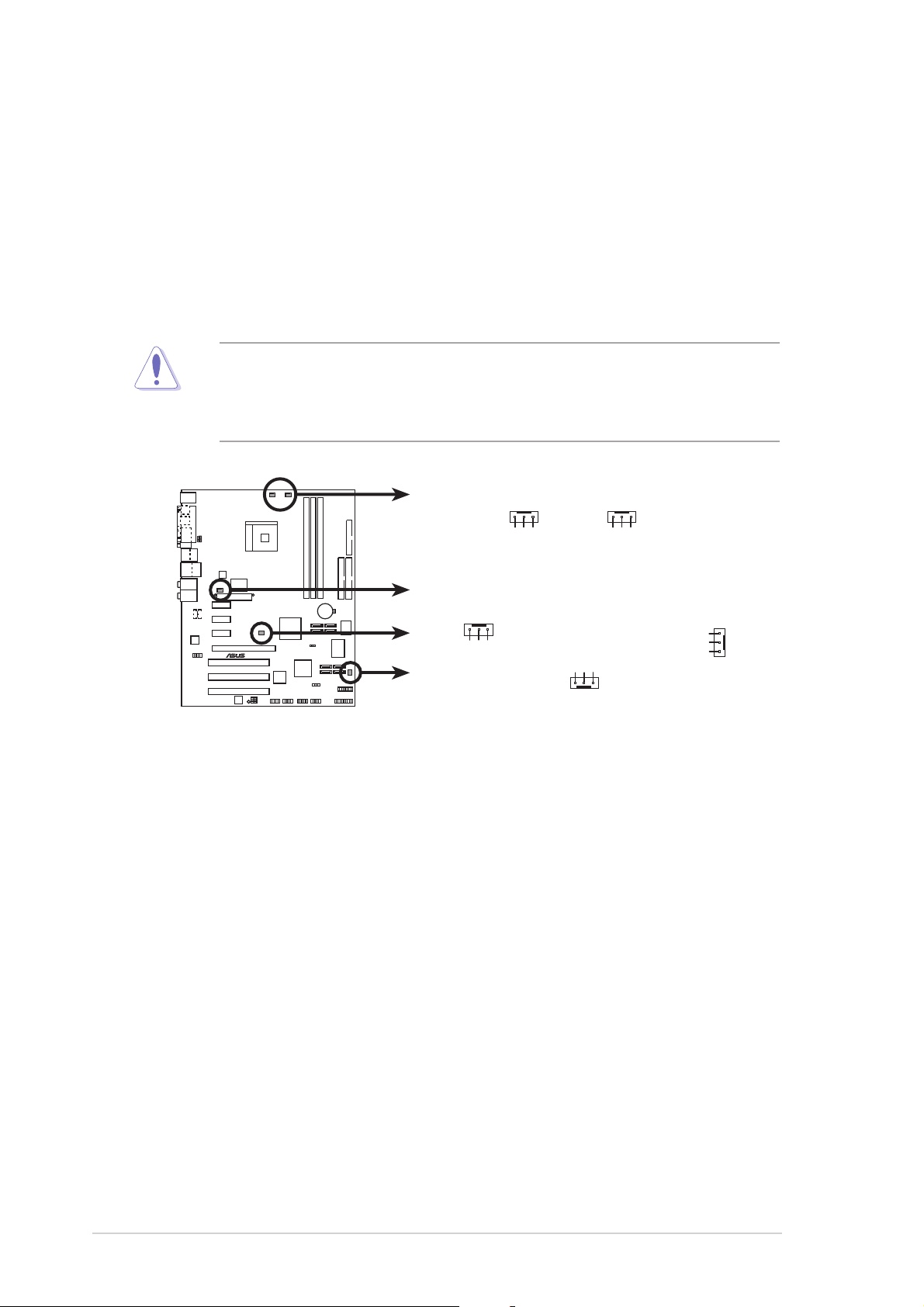
5.5.
®
CPU, Chassis and Power fan connectorsCPU, Chassis and Power fan connectors
5.
CPU, Chassis and Power fan connectors
5.5.
CPU, Chassis and Power fan connectorsCPU, Chassis and Power fan connectors
(3-pin CPU_FAN, 3-pin CHA1_FAN, 3-pin CHA2_FAN,(3-pin CPU_FAN, 3-pin CHA1_FAN, 3-pin CHA2_FAN,
(3-pin CPU_FAN, 3-pin CHA1_FAN, 3-pin CHA2_FAN,
(3-pin CPU_FAN, 3-pin CHA1_FAN, 3-pin CHA2_FAN,(3-pin CPU_FAN, 3-pin CHA1_FAN, 3-pin CHA2_FAN,
3-pin CHIP_FAN, 3-pin PWR_FAN)3-pin CHIP_FAN, 3-pin PWR_FAN)
3-pin CHIP_FAN, 3-pin PWR_FAN)
3-pin CHIP_FAN, 3-pin PWR_FAN)3-pin CHIP_FAN, 3-pin PWR_FAN)
The fan connectors support cooling fans of 350 mA ~ 2000 mA (24 W
max.) or a total of 1 A ~ 3.48 A (41.76 W max.) at +12 V. Connect
the fan cables to the fan connectors on the motherboard, making sure
that the black wire of each cable matches the ground pin of the
connector.
Do not forget to connect the fan cables to the fan connectors.
Insufficient air flow inside the system may damage the motherboard
components. These are not jumpers! DO NOT place jumper caps on the
fan connectors.
PWR_FAN
K8N4-E
K8N4-E DELUXE Fan connectors
CPU_FAN
Rotation
GND
+12V
Rotation
CHA2_FAN
GND
+12V
CHIP_FAN
GND
+12V
+12V
Rotation
Rotation
GND
CHA1_FAN
Rotation
+12V
GND
2-242-24
2-24
2-242-24
Chapter 2: Hardware informationChapter 2: Hardware information
Chapter 2: Hardware information
Chapter 2: Hardware informationChapter 2: Hardware information
Page 49
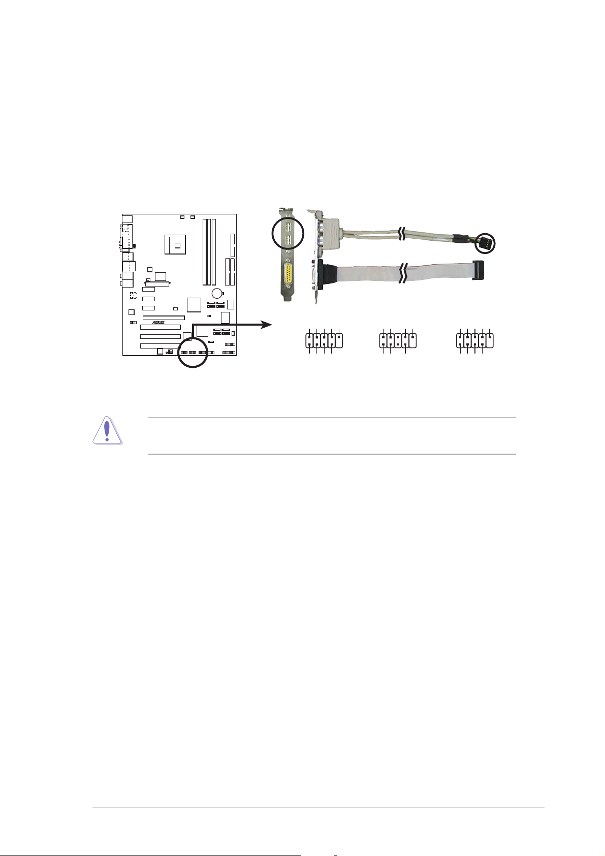
6.6.
®
USB connectors (10-1 pin USB56, USB78, USB910)USB connectors (10-1 pin USB56, USB78, USB910)
6.
USB connectors (10-1 pin USB56, USB78, USB910)
6.6.
USB connectors (10-1 pin USB56, USB78, USB910)USB connectors (10-1 pin USB56, USB78, USB910)
These connectors are for USB 2.0 ports. Connect the USB/GAME
module cable to any of these connectors, then install the module to a
slot opening at the back of the system chassis. These USB connectors
comply with USB 2.0 specification that supports up to 480 Mbps
connection speed.
K8N4-E
USB+5V
USB_P6-
USB_P6+
GND
USB56
NC
USB78
1
USB+5V
1
USB_P8-
USB_P8+
GND
NC
USB910
USB+5V
1
USB_P10-
USB_P10+
GND
NC
K8N4-E DELUXE
USB 2.0 connectors
Never connect a
damage the motherboard!
USB+5V
USB_P7-
USB_P7+
GND
GND
USB+5V
USB_P5-
USB_P5+
1394 cable1394 cable
1394 cable to the USB connectors. Doing so will
1394 cable1394 cable
USB+5V
USB_P9-
USB_P9+
GND
ASUS K8N4-E DeluxeASUS K8N4-E Deluxe
ASUS K8N4-E Deluxe
ASUS K8N4-E DeluxeASUS K8N4-E Deluxe
2-252-25
2-25
2-252-25
Page 50

7.7.
ATX power connectors (24-pin EATXPWR, 4-pin ATX12V)ATX power connectors (24-pin EATXPWR, 4-pin ATX12V)
7.
ATX power connectors (24-pin EATXPWR, 4-pin ATX12V)
7.7.
ATX power connectors (24-pin EATXPWR, 4-pin ATX12V)ATX power connectors (24-pin EATXPWR, 4-pin ATX12V)
These connectors are for an ATX power supply. The plugs from the
power supply are designed to fit these connectors in only one
orientation. Find the proper orientation and push down firmly until the
connectors completely fit.
•
We recommend that you use an ATX 12 V Specification
2.0-compliant power supply unit (PSU) with a minimum of 350 W
power rating. This PSU type has 24-pin and 4-pin power plugs.
•
If you intend to use a PSU with 20-pin and 4-pin power plugs, make
sure that the 20-pin power plug can provide at least 15A on +12V
and that the PSU has a minimum power rating of 350 W. The system
may become unstable or may not boot up if the power is
inadequate.
•
Do not forget to connect the 4-pin ATX +12 V power plug;
otherwise, the system will not boot up.
• We recommend that you use a PSU with higher power output when
configuring a system with more power-consuming devices. The
system may become unstable or may not boot up if the power is
inadequate.
• The ATX 12 V Specification 2.0-compliant PSU passed the
motherboard power requirement test with the following
configuration:
®
CPU : Intel
Memory : 512 MB DDR (x 4)
Graphics card : PCI Express x16 Nvidia EN5900
Parallel ATA devices: IDE hard disk drive (x 2)
Serial ATA device : SATA hard disk drive
Optical drives : CD-ROM (x 2)
SCSI devices : SCSI card and SCSI hard disk drive
• You must install a PSU with a higher power rating if you intend to
install additional devices.
Pentium® 4 3.6 GHz
2-262-26
2-26
2-262-26
Chapter 2: Hardware informationChapter 2: Hardware information
Chapter 2: Hardware information
Chapter 2: Hardware informationChapter 2: Hardware information
Page 51
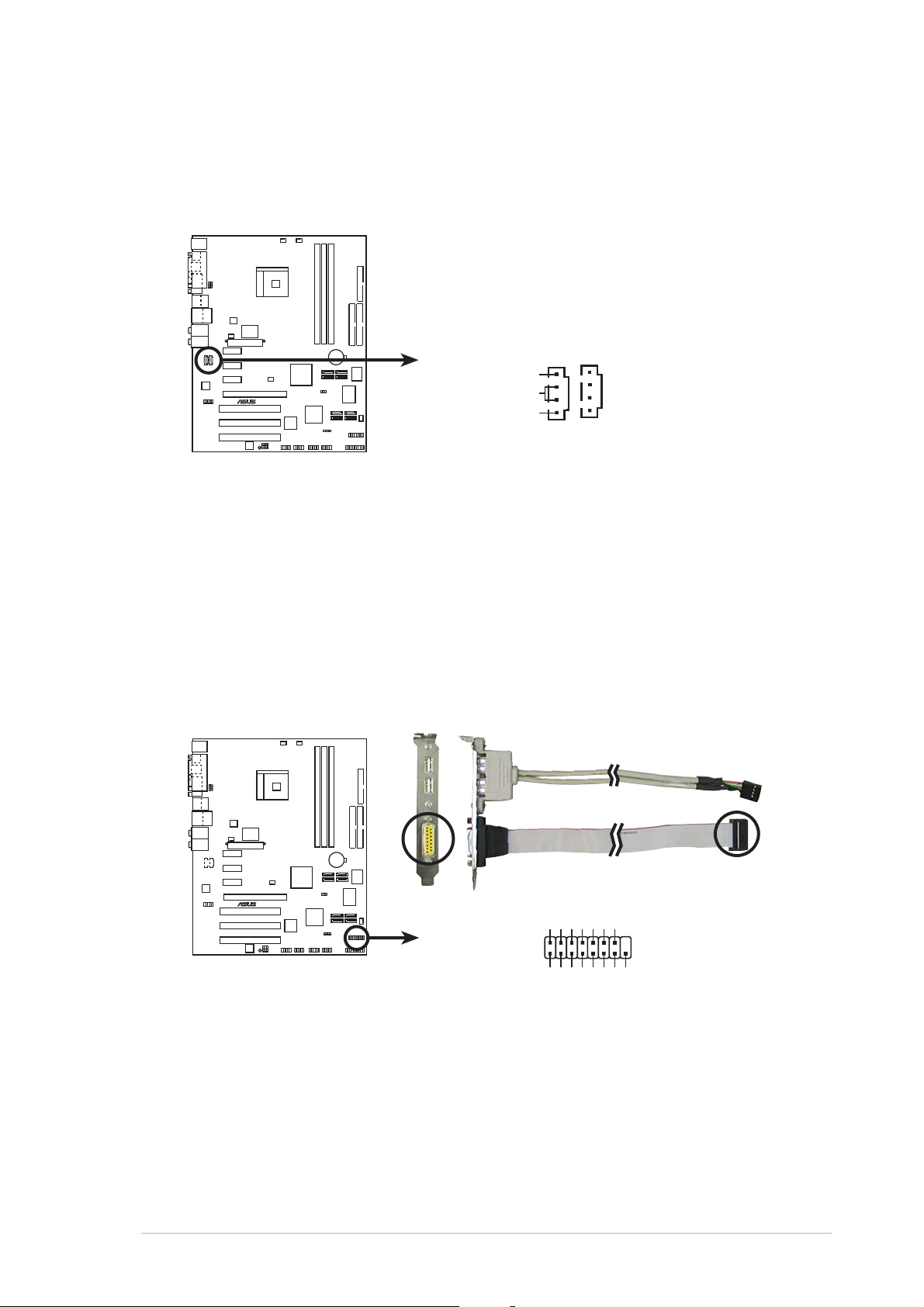
8.8.
®
)
®
Internal audio connectors (4-pin CD, AUX)Internal audio connectors (4-pin CD, AUX)
8.
Internal audio connectors (4-pin CD, AUX)
8.8.
Internal audio connectors (4-pin CD, AUX)Internal audio connectors (4-pin CD, AUX)
These connectors allow you to receive stereo audio input from sound
sources such as a CD-ROM, TV tuner, or MPEG card.
AUX (White
K8N4-E
CD (Black)
Right Audio Channel
Ground
Left Audio Channel
K8N4-E DELUXE Internal audio connectors
9.9.
GAME/MIDI port connector (16-1 pin GAME)GAME/MIDI port connector (16-1 pin GAME)
9.
GAME/MIDI port connector (16-1 pin GAME)
9.9.
GAME/MIDI port connector (16-1 pin GAME)GAME/MIDI port connector (16-1 pin GAME)
This connector is for a GAME/MIDI port. Connect the USB/GAME
module cable to this connector, then install the module to a slot
opening at the back of the system chassis. The GAME/MIDI port
connects a joystick or game pad for playing games, and MIDI devices
for playing or editing audio files.
K8N4-E
J2B1
J2CX
MIDI_OUT
J2CY
J2B2
MIDI_IN
GAME
K8N4-E DELUXE Game connector
ASUS K8N4-E DeluxeASUS K8N4-E Deluxe
ASUS K8N4-E Deluxe
ASUS K8N4-E DeluxeASUS K8N4-E Deluxe
+5V +5V
J1B1
J1CX
GND
GND
J1CY
+5V
J1B2
2-272-27
2-27
2-272-27
Page 52
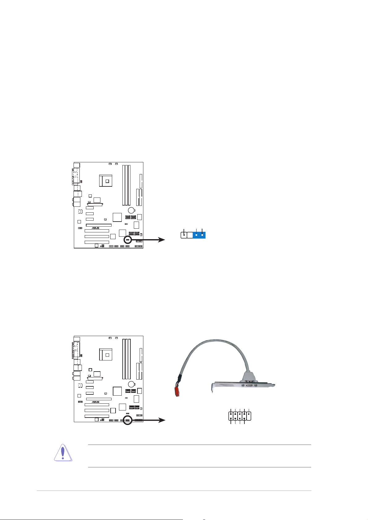
10.10.
®
r
®
Chassis intrusion connector (4-1 pin CHASSIS)Chassis intrusion connector (4-1 pin CHASSIS)
10.
Chassis intrusion connector (4-1 pin CHASSIS)
10.10.
Chassis intrusion connector (4-1 pin CHASSIS)Chassis intrusion connector (4-1 pin CHASSIS)
This connector is for a chassis-mounted intrusion detection sensor or
switch. Connect one end of the chassis intrusion sensor or switch
cable to this connector. The chassis intrusion sensor or switch sends a
high-level signal to this connector when a chassis component is
removed or replaced. The signal is then generated as a chassis
intrusion event.
By default, the pins labeled “Chassis Signal” and “Ground” are shorted
with a jumper cap. Remove the jumper caps only when you intend to
use the chassis intrusion detection feature.
CHASSIS
K8N4-E
+5VSB_MB
Chassis Signal
GND
(Default)
K8N4-E DELUXE Chassis intrusion connecto
11.11.
IEEE 1394a connector (10-1 pin IE1394_2)IEEE 1394a connector (10-1 pin IE1394_2)
11.
IEEE 1394a connector (10-1 pin IE1394_2)
11.11.
IEEE 1394a connector (10-1 pin IE1394_2)IEEE 1394a connector (10-1 pin IE1394_2)
This connector is for an IEEE 1394a port. Connect the IEEE 1394a
module cable to this connector, then install the module to a slot
opening at the back of the system chassis.
K8N4-E
TPA0-
GND
TPB0-
+12V
GND
IE1394_2
1
K8N4-E DELUXE IEEE-1394 connector
NEVER connect a
USB cable USB cable
U S B c a b l e to the IEEE 1394a connector. Doing so
USB cable USB cable
TPA0+
GND
TPB0+
+12V
will damage the motherboard!
2-282-28
2-28
2-282-28
Chapter 2: Hardware informationChapter 2: Hardware information
Chapter 2: Hardware information
Chapter 2: Hardware informationChapter 2: Hardware information
Page 53

12.12.
®
FF
12.
12.12.
ront panel audio connector (10-1 pin 2 x 5-pin FP_AUDIO)ront panel audio connector (10-1 pin 2 x 5-pin FP_AUDIO)
F
ront panel audio connector (10-1 pin 2 x 5-pin FP_AUDIO)
FF
ront panel audio connector (10-1 pin 2 x 5-pin FP_AUDIO)ront panel audio connector (10-1 pin 2 x 5-pin FP_AUDIO)
This connector is for a chassis-mounted front panel audio I/O module
that supports either HD Audio or legacy AC ‘97 audio standard.
Connect one end of the front panel audio I/O module cable to this
connector.
BLINE_OUT_L
+5VA
BLINE_OUT_R
AGND
K8N4-E
K8N4-E DELUXE Front panel audio connector
We recommend that you connect a high-definition front panel audio
module to this connector to avail of the motherboard’s high-definition
audio capability.
FP_AUDIO
MIC2
MICPWR
NC
Line out_L
Line out_R
ASUS K8N4-E DeluxeASUS K8N4-E Deluxe
ASUS K8N4-E Deluxe
ASUS K8N4-E DeluxeASUS K8N4-E Deluxe
2-292-29
2-29
2-292-29
Page 54
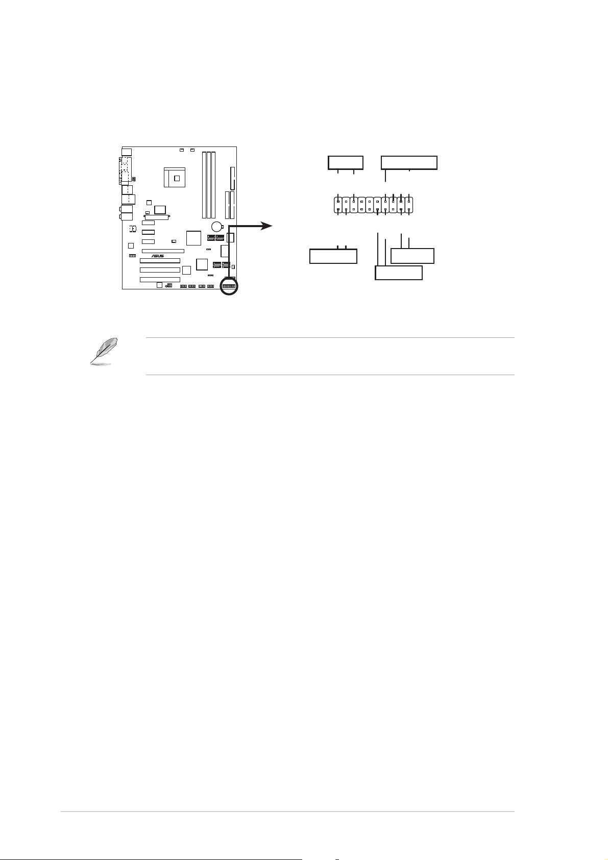
13.13.
®
y.
System panel connector (20-pin PANEL)System panel connector (20-pin PANEL)
13.
System panel connector (20-pin PANEL)
13.13.
System panel connector (20-pin PANEL)System panel connector (20-pin PANEL)
This connector supports several chassis-mounted functions.
PLED
PLED+
PLED-
SPEAKER
Speaker
Ground
+5V
Ground
PANEL
PWR
Reset
Ground
K8N4-E
IDE_LED-
IDE_LED+
IDE_LED
* Requires an ATX power suppl
Ground
RESET
PWRSW
K8N4-E DELUXE System panel connector
The sytem panel connector is color-coded for easy connection. Refer to
the connector description below for details.
System power LED (Green 3-pin PLED)System power LED (Green 3-pin PLED)
•
System power LED (Green 3-pin PLED)
System power LED (Green 3-pin PLED)System power LED (Green 3-pin PLED)
This 3-pin connector is for the system power LED. Connect the
chassis power LED cable to this connector. The system power LED
lights up when you turn on the system power, and blinks when the
system is in sleep mode.
Hard disk drive activity (Red 2-pin IDE_LED)Hard disk drive activity (Red 2-pin IDE_LED)
•
Hard disk drive activity (Red 2-pin IDE_LED)
Hard disk drive activity (Red 2-pin IDE_LED)Hard disk drive activity (Red 2-pin IDE_LED)
This 2-pin connector is for the HDD Activity LED. Connect the HDD
Activity LED cable to this connector. The IDE LED lights up or flashes
when data is read from or written to the HDD.
System warning speaker (Orange 4-pin SPEAKER)System warning speaker (Orange 4-pin SPEAKER)
•
System warning speaker (Orange 4-pin SPEAKER)
System warning speaker (Orange 4-pin SPEAKER)System warning speaker (Orange 4-pin SPEAKER)
This 4-pin connector is for the chassis-mounted system warning
speaker. The speaker allows you to hear system beeps and warnings.
Power/Soft-off button (Yellow 2-pin PWRSW)Power/Soft-off button (Yellow 2-pin PWRSW)
•
Power/Soft-off button (Yellow 2-pin PWRSW)
Power/Soft-off button (Yellow 2-pin PWRSW)Power/Soft-off button (Yellow 2-pin PWRSW)
This connector is for the system power button. Pressing the power
button turns the system ON or puts the system in SLEEP or SOFT-OFF
mode depending on the BIOS settings. Pressing the power switch for
more than four seconds while the system is ON turns the system OFF.
Reset button (Blue 2-pin RESET)Reset button (Blue 2-pin RESET)
•
Reset button (Blue 2-pin RESET)
Reset button (Blue 2-pin RESET)Reset button (Blue 2-pin RESET)
This 2-pin connector is for the chassis-mounted reset button for
system reboot without turning off the system power.
2-302-30
2-30
2-302-30
Chapter 2: Hardware informationChapter 2: Hardware information
Chapter 2: Hardware information
Chapter 2: Hardware informationChapter 2: Hardware information
Page 55

This chapter describes the power up
sequence, the vocal POST messages,
and ways of shutting down the
system.
Powering up
3
Page 56

Chapter summary
3
3.1 Starting up for the first time................................................ 3-1
3.2 Powering off the computer .................................................. 3-2
3.3 ASUS POST Reporter™ .......................................................... 3-3
3.3.1 Vocal POST messages ............................................ 3-3
3.3.2 Winbond Voice Editor ............................................. 3-5
ASUS K8N4-E DeluxeASUS K8N4-E Deluxe
ASUS K8N4-E Deluxe
ASUS K8N4-E DeluxeASUS K8N4-E Deluxe
Page 57

3.1 Starting up for the first time
1. After making all the connections, replace the system case cover.
2. Be sure that all switches are off.
3. Connect the power cord to the power connector at the back of the
system chassis.
4. Connect the power cord to a power outlet that is equipped with a
surge protector.
5. Turn on the devices in the following order:
a. Monitor
b. External SCSI devices (starting with the last device on the chain)
c. System power
6. After applying power, the system power LED on the system front
panel case lights up. For systems withATX power supplies, the system
LED lights up when you press the ATX power button. If your monitor
complies with “green” standards or if it has a “power standby”
feature, the monitor LED may light up or switch between orange and
green after the system LED turns on.
The system then runs the power-on self tests or POST. While the
tests are running, the BIOS beeps (see BIOS beep codes table below)
or additional messages appear on the screen. If you do not see
anything within 30 seconds from the time you turned on the power,
the system may have failed a power-on test. Check the jumper
settings and connections or call your retailer for assistance.
7. At power on, hold down the <Delete> key to enter the BIOS Setup.
Follow the instructions in Chapter 4.
ASUS K8N4-E DeluxeASUS K8N4-E Deluxe
ASUS K8N4-E Deluxe
ASUS K8N4-E DeluxeASUS K8N4-E Deluxe
3-13-1
3-1
3-13-1
Page 58

3.2 Powering off the computer
3.2.13.2.1
3.2.1
3.2.13.2.1
If you are using Windows® 2000:
1. Click the
2. Make sure that the
the
3. The power supply should turn off after Windows
If you are using Windows
1. Click the
2. Click the
3. The power supply should turn off after Windows
3.2.23.2.2
3.2.2
3.2.23.2.2
While the system is ON, pressing the power switch for less than four
seconds puts the system to sleep mode or to soft-off mode, depending on
the BIOS setting. Pressing the power switch for more than four seconds
lets the system enter the soft-off mode regardless of the BIOS setting.
Refer to section “4.5 Power Menu” in Chapter 4 for details.
Using the OS shut down functionUsing the OS shut down function
Using the OS shut down function
Using the OS shut down functionUsing the OS shut down function
Start Start
Start button then click
Start Start
Shut DownShut Down
Shut Down option button is selected, then click
Shut DownShut Down
OK OK
O K button to shut down the computer.
OK OK
®
XP:
Start Start
Start button then select
Start Start
Turn Off Turn Off
Turn Off button to shut down the computer.
Turn Off Turn Off
Using the dual function power switchUsing the dual function power switch
Using the dual function power switch
Using the dual function power switchUsing the dual function power switch
Shut Down...Shut Down...
Shut Down...
Shut Down...Shut Down...
®
shuts down.
Turn Off Computer.Turn Off Computer.
Turn Off Computer.
Turn Off Computer.Turn Off Computer.
®
shuts down.
3-23-2
3-2
3-23-2
Chapter 3: Powering upChapter 3: Powering up
Chapter 3: Powering up
Chapter 3: Powering upChapter 3: Powering up
Page 59

3.3 ASUS POST Reporter™
This motherboard includes the Winbond speech controller to support a
special feature called the ASUS POST Reporter™. This feature gives you
vocal POST messages and alerts you of system events and boot status. In
case of a boot failure, you will hear the specific cause of the problem.
These POST messages are customizable using the Winbond Voice Editor
software that came with your package. You can record your own messages
to replace the default messages.
3.3.13.3.1
3.3.1
3.3.13.3.1
Vocal POST messagesVocal POST messages
Vocal POST messages
Vocal POST messagesVocal POST messages
Following is a list of the default POST messages and the corresponding
actions you can take:
POST MessagePOST Message
POST Message
POST MessagePOST Message
No CPU installed
System failed CPU test
System failed memory test
System failed VGA test
System failed due to CPU
overclocking and set only to the recommended
No keyboard detected
No IDE hard disk detected • Make sure you have connected an IDE
•
Install a supported processor into
the CPU socket. See section “2.3
Central Processing Unit (CPU)” for
supported processors.
•
Check the CPU if properly installed.
•
Call ASUS technical support for
assistance. See the “ASUS contact
information” on the inside front cover
of this manual.
•
Install supported DDR DIMMs into the
sockets.
•
Check if the DIMMs on the DIMM sockets
are properly installed.
•
Make sure that your DIMMs are not
defective.
•
Refer to section “2.4 System memory”
for instructions on installing a DIMM.
•
Install a PCI VGA card into one of the
PCI slots, or a 1.5V AGP card into the
AGP slot.
•
Make sure that your VGA/AGP card is
not defective.
•
Check your CPU settings in the BIOS
•
Check if your keyboard is properly
connected to the purple PS/2
connector on the rear panel.
• See section “2.7.1 Rear panel
connectors” for the location of the
connector.
hard disk drive to one of the IDE
connectors on the motherboard.
ActionAction
Action
ActionAction
ASUS K8N4-E DeluxeASUS K8N4-E Deluxe
ASUS K8N4-E Deluxe
ASUS K8N4-E DeluxeASUS K8N4-E Deluxe
3-33-3
3-3
3-33-3
Page 60

POST MessagePOST Message
POST Message
POST MessagePOST Message
ActionAction
Action
ActionAction
CPU temperature too high
CPU fan failed
CPU voltage out of range
System completed Power-On Self Test • No action required
Computer now booting from operating • No action required
system
•
Check if the CPU fan is working
properly.
•
Check the CPU fan and make sure
it turns on after you apply power
to the system.
•
Make sure that your CPU fan
supports the fan speed detection
function.
•
Check your power supply and
make sure it is not defective.
•
Call ASUS technical support for
assistance. See the “ASUS contact
information” on the inside front
cover of this manual.
You can disable the ASUS POST Reporter™ in the BIOS setup. See section
“4.4.7 Speech configuration.”
3-43-4
3-4
3-43-4
Chapter 3: Powering upChapter 3: Powering up
Chapter 3: Powering up
Chapter 3: Powering upChapter 3: Powering up
Page 61

3.3.23.3.2
3.3.2
3.3.23.3.2
Winbond Voice EditorWinbond Voice Editor
Winbond Voice Editor
Winbond Voice EditorWinbond Voice Editor
The Winbond Voice Editor software allows you to customize the vocal
POST messages. Install the software from the utilities menu of the support
CD. See section “5.2.3 Utilities menu” for details.
To avoid conflicts, do not run the Winbond Voice Editor while running
the ASUS PC Probe.
Follow these steps to use the Winbond Voice Editor.
Launching the programLaunching the program
Launching the program
Launching the programLaunching the program
Launch the program either from the Winbond Voice Editor icon on your
desktop, or from the Windows Start menu, select
Voice Editor->Voice EditorVoice Editor->Voice Editor
Voice Editor->Voice Editor.
Voice Editor->Voice EditorVoice Editor->Voice Editor
Programs->WinbondPrograms->Winbond
Programs->Winbond
Programs->WinbondPrograms->Winbond
The Winbond Voice Editor screen appears.
POST EventsPOST Events
POST Events
POST EventsPOST Events
Playing the default wave filesPlaying the default wave files
Playing the default wave files
Playing the default wave filesPlaying the default wave files
Default MessagesDefault Messages
Default Messages
Default MessagesDefault Messages
To play the default wave files, simply click on a POST event on the left side
of the screen, then click the Play button.
The default language setting is English.
ASUS K8N4-E DeluxeASUS K8N4-E Deluxe
ASUS K8N4-E Deluxe
ASUS K8N4-E DeluxeASUS K8N4-E Deluxe
3-53-5
3-5
3-53-5
Page 62

Changing the default languageChanging the default language
Changing the default language
Changing the default languageChanging the default language
1. Click the
LoadLoad
Load button. A
LoadLoad
window showing the available
languages appears.
2. Select your desired language,
then click
OpenOpen
O p e n. The event
OpenOpen
messages for the language you
selected appear on the Voice
Editor screen.
For some languages, not all events have a corresponding message due
to file size constraints.
3. Click the
Write Write
Write button to
Write Write
update the EEPROM.
4. Click
Yes Yes
Yes on the confirmation
Yes Yes
window that appears.
The next time you boot your computer, the POST messages are announced
in the language that you selected .
3-63-6
3-6
3-63-6
Chapter 3: Powering upChapter 3: Powering up
Chapter 3: Powering up
Chapter 3: Powering upChapter 3: Powering up
Page 63

Customizing your POST messagesCustomizing your POST messages
Customizing your POST messages
Customizing your POST messagesCustomizing your POST messages
If your language is not in the selection or if you wish to record your own
POST messages to replace the pre-installed wave files, you may easily do
so.
Follow these steps to customize your POST messages.
1. Launch the Voice Editor and note the list of POST events on the
leftmost column of the screen.
2. Prepare your message for each event.
The total compressed size for all the wave files must not exceed 1Mbit,
so keep your messages as short as possible.
3. Use a recording software, such as Windows Recorder, to record your
messages.
4. Save the messages as wave files (.WAV). To keep file sizes small,
save your files at a low quality. For example, use 8-bit, mono quality
at 22 Khz sampling rate.
You may want to create a separate folder for your wave files so you can
locate them easily in one place.
5. From the Voice Editor screen,
click the
Add Add
Add button to
Add Add
display the Add Wave File
window.
6. Copy the wave files that you
recorded to the database.
Close the window when done.
ASUS K8N4-E DeluxeASUS K8N4-E Deluxe
ASUS K8N4-E Deluxe
ASUS K8N4-E DeluxeASUS K8N4-E Deluxe
3-73-7
3-7
3-73-7
Page 64
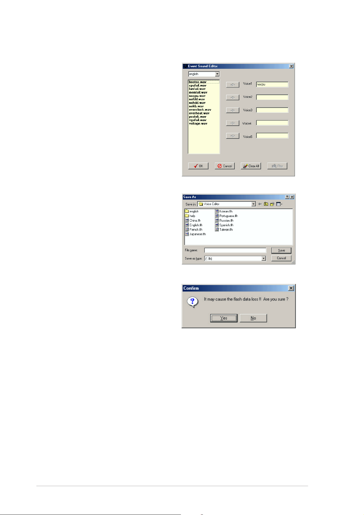
7. Select a POST event on the
Voice Editor screen, then click
Edit Edit
the
Edit button. The Event
Edit Edit
Sound Editor window appears.
8. Locate and select your wave
file for the event, then click
on the arrow opposite Voice1.
The file you select appears on
the space next to it.
9. Click
OK OK
O K to return to the
OK OK
Voice Editor screen.
10. Do steps 7 to 9 for the other
events.
11. When done, click
SaveSave
S a v e. A
SaveSave
window appears prompting
you to save your
configuration.
12. Type a file name with an
.flh.flh
.flh
.flh.flh
extension, then click Save.
13. Click the
Write Write
Write button to
Write Write
compress the file and copy
into the EEPROM.
14. Click
Yes Yes
Yes on the confirmation
Yes Yes
window that appears.
If you receive an error message telling you that the files exceed the total
allowable size, do one or all of the following.
•
Shorten your messages.
•
Save the wave files at a lower quality
•
Skip seldom-used events like FDD Detection, IDE HDD Detection, etc.
3-83-8
3-8
3-83-8
Chapter 3: Powering upChapter 3: Powering up
Chapter 3: Powering up
Chapter 3: Powering upChapter 3: Powering up
Page 65

This chapter tells how to change
the system settings through the BIOS
Setup menus. Detailed descriptions
of the BIOS parameters are also
provided.
BIOS setup
4
Page 66

Chapter summary
4
4.1 Managing and updating your BIOS ........................................ 4-1
4.2 BIOS setup program ........................................................... 4-11
4.3 Main menu .......................................................................... 4-14
4.4 Advanced menu .................................................................. 4-19
4.5 Power menu ........................................................................ 4-36
4.6 Boot menu .......................................................................... 4-41
4.7 Exit menu ........................................................................... 4-46
ASUS K8N4-E DeluxeASUS K8N4-E Deluxe
ASUS K8N4-E Deluxe
ASUS K8N4-E DeluxeASUS K8N4-E Deluxe
Page 67
4.1 Managing and updating your BIOS
The following utilities allow you to manage and update the motherboard
Basic Input/Output System (BIOS) setup.
AwardBIOS Flash Utility AwardBIOS Flash Utility
1.
AwardBIOS Flash Utility (Updates the BIOS using a floppy disk
AwardBIOS Flash Utility AwardBIOS Flash Utility
during POST.)
ASUS EZ Flash ASUS EZ Flash
2.
ASUS EZ Flash (Updates the BIOS using a floppy disk during POST.)
ASUS EZ Flash ASUS EZ Flash
ASUS CrashFree BIOSASUS CrashFree BIOS
3.
ASUS CrashFree BIOS
ASUS CrashFree BIOSASUS CrashFree BIOS
UtilityUtility
Utility (Updates the BIOS using a bootable
UtilityUtility
floppy disk when the BIOS gets corrupted.)
ASUS UpdateASUS Update
4.
ASUS Update (Updates the BIOS in Windows
ASUS UpdateASUS Update
®
environment.)
Refer to the corresponding section for details on these utilities.
Important notesImportant notes
Important notes
Important notesImportant notes
original motherboard BIOS fileoriginal motherboard BIOS file
original motherboard BIOS file to a
original motherboard BIOS fileoriginal motherboard BIOS file
4.1.14.1.1
4.1.1
4.1.14.1.1
• Save a copy of the
bootable floppy diskbootable floppy disk
bootable floppy disk in case you need to restore the BIOS in
bootable floppy diskbootable floppy disk
the future. Copy the original motherboard BIOS using the ASUS
Update or AFLASH utilities.
• Visit the system builder’s website and download the latest BIOS file
for this motherboard using the ASUS Update utility.
Creating a bootable floppy diskCreating a bootable floppy disk
Creating a bootable floppy disk
Creating a bootable floppy diskCreating a bootable floppy disk
1. Do either one of the following to create a bootable floppy disk.
DOS environment
a. Insert a 1.44 MB floppy disk into the drive.
b. At the DOS prompt, type format A:/S
then press <Enter>.
Windows® XP environment
a. Insert a 1.44 MB floppy disk to the floppy disk drive.
b. Click
ComputerComputer
Computer.
ComputerComputer
Start Start
Start from the Windows
Start Start
®
desktop, then select
MyMy
My
MyMy
c. Select the 3 1/2 Floppy Drive icon.
d. Click
e. Select
File File
File from the menu, then select
File File
Floppy DiskFloppy Disk
Floppy Disk window appears.
Floppy DiskFloppy Disk
Create an MS-DOS startup disk Create an MS-DOS startup disk
Create an MS-DOS startup disk from the format
Create an MS-DOS startup disk Create an MS-DOS startup disk
options field, then click
StartStart
Start.
StartStart
FormatFormat
Format. A
FormatFormat
Format 3 1/2Format 3 1/2
Format 3 1/2
Format 3 1/2Format 3 1/2
ASUS K8N4-E DeluxeASUS K8N4-E Deluxe
ASUS K8N4-E Deluxe
ASUS K8N4-E DeluxeASUS K8N4-E Deluxe
4-14-1
4-1
4-14-1
Page 68

Windows® 2000 environment
To create a set of boot disks for Windows® 2000:
a. Insert a formatted, high density 1.44 MB floppy disk into the drive.
®
b. Insert the Windows
2000 CD to the optical drive.
c. Click
d. From the Open field, type
e. Press <Enter>, then follow screen instructions to continue.
2. Copy the original or the latest motherboard BIOS file to the bootable
floppy disk.
4.1.24.1.2
4.1.2
4.1.24.1.2
The Basic Input/Output System (BIOS) can be updated using the built-in
Flash Memory Writer utility or using a bootable floppy disk with the
executable Flash Memory Writer Utility (AWDFLASH.EXE). Follow these
instructions to update the BIOS using this utility.
StartStart
Start, then select
StartStart
D:\bootdisk\makeboot a:
assuming that D: is your optical drive.
AwardBIOS Flash UtilityAwardBIOS Flash Utility
AwardBIOS Flash Utility
AwardBIOS Flash UtilityAwardBIOS Flash Utility
Save only the updated BIOS file in the floppy disk to avoid loading a
wrong BIOS file.
RunRun
Run.
RunRun
The succeeding screens are for reference only. The actual displays may
not exactly match what you see on your screen.
Updating the BIOS fileUpdating the BIOS file
Updating the BIOS file
Updating the BIOS fileUpdating the BIOS file
1. Download the latest BIOS file from the system builder’s website. .
Rename the file to (BIOS file name on the support CD).BIN and save it
to the bootable floppy disk you created earlier.
2. Copy the AwardBIOS Flash Utility (awdflash.exe) from the Software
folder of the support CD to the floppy disk with the latest BIOS file.
3. Boot the system in DOS mode using the bootable floppy disk you
created earlier.
4-24-2
4-2
4-24-2
Chapter 4: BIOS setupChapter 4: BIOS setup
Chapter 4: BIOS setup
Chapter 4: BIOS setupChapter 4: BIOS setup
Page 69
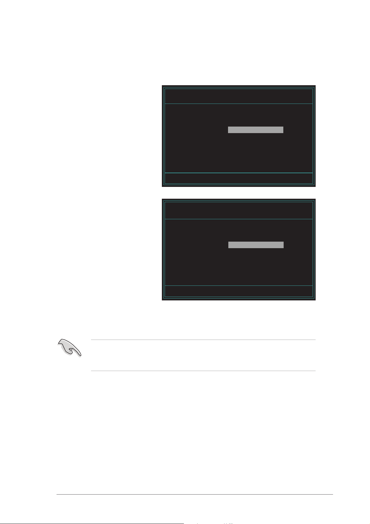
4. When the
A:>A:>
A : > appears, replace the bootable floppy disk with the
A:>A:>
floppy disk containing the new BIOS file and the Award BIOS Flash
Utility.
5. At the prompt, type
awdflashawdflash
awdflash then press
awdflashawdflash
<Enter>. The Award
BIOS Flash Utility screen
appears.
6. Type the BIOS file name
in the
ProgramProgram
Program field, then
ProgramProgram
File Name toFile Name to
File Name to
File Name toFile Name to
press <Enter>.
AwardBIOS Flash Utility for ASUS V1.09
(C) Phoenix Technologies Ltd. All Rights Reserved
For NF-CK804-K8N4-E-00 DATE: 12/16/2004
Flash Type - SST 49LF004A/B /3.3V
File Name to Program:
Message: Please input File Name!
AwardBIOS Flash Utility for ASUS V1.09
(C) Phoenix Technologies Ltd. All Rights Reserved
For NF-CK804-K8N4-E-00 DATE: 12/16/2004
Flash Type - SST 49LF004A/B /3.3V
File Name to Program: 1231A.bin
Message: Do You Want To Save Bios (Y/N)
7. The utility prompts you to save the current BIOS file. Press <Y> to
save the current BIOS file to the floppy disk, or <N> to continue.
If you intend to save the current BIOS file, make sure that the floppy
disk has enough disk space to save the file. See the next section for
details on saving the current BIOS file.
ASUS K8N4-E DeluxeASUS K8N4-E Deluxe
ASUS K8N4-E Deluxe
ASUS K8N4-E DeluxeASUS K8N4-E Deluxe
4-34-3
4-3
4-34-3
Page 70

8. The utility verifies the
3
1
1
3
123
123
123
3
3
123
123
123
BIOS file in the floppy
disk and starts flashing
the BIOS file.
AwardBIOS Flash Utility for ASUS V1.09
(C) Phoenix Technologies Ltd. All Rights Reserved
For NF-CK804-K8N4-E-00 DATE: 12/16/2004
Flash Type - SST 49LF004A/B /3.3V
File Name to Program: 1231A.bin
Program Flashing Memory - OFE00 OK
23456789012345678901234567890
23456789012345678901234567890
Do not turn off or reset the system during the flashing process!
9. The utility displays a
Flashing CompleteFlashing Complete
Flashing Complete
Flashing CompleteFlashing Complete
message indicating that
you have successfully
flashed the BIOS file.
Remove the floppy disk
then press <F1> to
restart the system.
2
Write OK No Update Write Fail
2
Warning: Don’t Turn Off Power Or Reset System!
AwardBIOS Flash Utility for ASUS V1.09
(C) Phoenix Technologies Ltd. All Rights Reserved
For NF-CK804-K8N4-E-00 DATE: 12/16/2004
Flash Type - SST 49LF004A/B /3.3V
File Name to Program: 1231A.bin
Flashing Complete
Press <F1> to Continue
2
Write OK No Update Write Fail
F1
Reset
2
4-44-4
4-4
4-44-4
Chapter 4: BIOS setupChapter 4: BIOS setup
Chapter 4: BIOS setup
Chapter 4: BIOS setupChapter 4: BIOS setup
Page 71
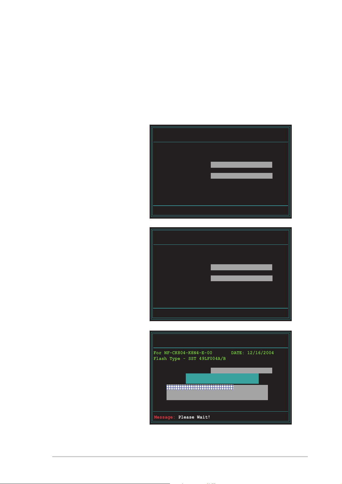
Saving the current BIOS fileSaving the current BIOS file
1
Saving the current BIOS file
Saving the current BIOS fileSaving the current BIOS file
You can use the AwardBIOS Flash Utility to save the current BIOS file. You
can load the current BIOS file when the BIOS file gets corrupted during the
flashing process.
To save the current BIOS file using the AwardBIOS Flash Utility:
1. Follow steps 1 to 6 of the previous section.
2. Press <Y> when the
utility prompts you to
AwardBIOS Flash Utility for ASUS V1.09
(C) Phoenix Technologies Ltd. All Rights Reserved
save the current BIOS
file. The following screen
For NF-CK804-K8N4-E-00 DATE: 12/16/2004
Flash Type - SST 49LF004A/B /3.3V
appears.
File Name to Program: 1231A.bin
Save current BIOS as:
Message:
3. Type a filename for the
current BIOS file in the
Save current BIOSSave current BIOS
Save current BIOS
Save current BIOSSave current BIOS
as as
a s field, then press
as as
<Enter>.
4. The utility saves the
current BIOS file to the
floppy disk, then returns
to the BIOS flashing
process.
AwardBIOS Flash Utility for ASUS B107A
(C) Phoenix Technologies Ltd. All Rights Reserved
For NF-CK804-K8N4-E-00 DATE: 12/16/2004
Flash Type - SST 49LF004A/B /3.3V
File Name to Program: 1231A.bin
Checksum: 6772H
Save current BIOS as: old.bin
Message: Please Wait!
AwardBIOS Flash Utility for ASUS V1.09
(C) Phoenix Technologies Ltd. All Rights Reserved
For NF-CK804-K8N4-E-00 DATE: 12/16/2004
Flash Type - SST 49LF004A/B /3.3V
File Name to Program: 1231A.bin
Now Backup System BIOS to
File!
23456789012345678901234567890
ASUS K8N4-E DeluxeASUS K8N4-E Deluxe
ASUS K8N4-E Deluxe
ASUS K8N4-E DeluxeASUS K8N4-E Deluxe
Message: Please Wait!
4-54-5
4-5
4-54-5
Page 72

4.1.34.1.3
4.1.3
4.1.34.1.3
ASUS EZ Flash utilityASUS EZ Flash utility
ASUS EZ Flash utility
ASUS EZ Flash utilityASUS EZ Flash utility
The ASUS EZ Flash feature allows you to update the BIOS without having to
go through the long process of booting from a floppy disk and using a
DOS-based utility. The EZ Flash utility is built-in the BIOS chip so it is
accessible by pressing <Alt> + <F2> during the Power-On Self Tests
(POST).
To update the BIOS using EZ Flash:
1. Visit the ASUS website (www.asus.com) to download the latest BIOS
file for the motherboard and rename the same to
K8N4-E.ROMK8N4-E.ROM
K8N4-E.ROM.
K8N4-E.ROMK8N4-E.ROM
2. Save the BIOS file to a floppy disk, then restart the system.
3. Press <Alt> + <F2> during POST to display the following.
EZFlash starting BIOS update
Checking for floppy...
4. Insert the floppy disk that contains the BIOS file to the floppy disk
drive. When the correct BIOS file is found, EZ Flash performs the BIOS
update process and automatically reboots the system when done.
EZFlash starting BIOS update
Checking for floppy...
Floppy found!
Reading file “K8N4-E.ROM”. Completed.
Start erasing.......|
Start programming...|
Flashed successfully. Rebooting.
• Do not shut down or reset the system while updating the BIOS to
prevent system boot failure!
• A “Floppy not found!” error message appears if there is no floppy
disk in the drive. An “K8N4-E.ROM not found!” error message
appears if the correct BIOS file is not found in the floppy disk. Make
sure that you rename the BIOS file to K8N4-E.ROM.
4-64-6
4-6
4-64-6
Chapter 4: BIOS setupChapter 4: BIOS setup
Chapter 4: BIOS setup
Chapter 4: BIOS setupChapter 4: BIOS setup
Page 73

4.1.44.1.4
4.1.4
4.1.44.1.4
ASUS CrashFree BIOS 2 utilityASUS CrashFree BIOS 2 utility
ASUS CrashFree BIOS 2 utility
ASUS CrashFree BIOS 2 utilityASUS CrashFree BIOS 2 utility
The ASUS CrashFree BIOS is an auto recovery tool that allows you to
restore the BIOS file when it fails or gets corrupted during the updating
process. You can update a corrupted BIOS file using the motherboard
support CD or the floppy disk that contains the updated BIOS file.
• Prepare the floppy disk containing the updated motherboard BIOS
before using this utility.
• Make sure that you rename the original or updated BIOS file in the
floppy disk to
Recovering the BIOS from a floppy diskRecovering the BIOS from a floppy disk
Recovering the BIOS from a floppy disk
Recovering the BIOS from a floppy diskRecovering the BIOS from a floppy disk
K8N4-E.ROMK8N4-E.ROM
K8N4-E.ROM.
K8N4-E.ROMK8N4-E.ROM
To recover the BIOS from a floppy disk:
1. Turn on the system.
2. Insert the floppy disk with the original or updated BIOS file to the
floppy disk drive.
3. The utility displays the following message and automatically checks
the floppy disk for the original or updated BIOS file.
Bad BIOS checksum. Starting BIOS recovery...
Checking for floppy...
When found, the utility reads the BIOS file and starts flashing the
corrupted BIOS file.
Bad BIOS checksum. Starting BIOS recovery...
Checking for floppy...
Floppy found!
Reading file “K8N4-E.ROM”. Completed.
Start flashing...
DO NOT shut down or reset the system while updating the BIOS! Doing
so can cause system boot failure!
4. Restart the system after the utility completes the updating process.
ASUS K8N4-E DeluxeASUS K8N4-E Deluxe
ASUS K8N4-E Deluxe
ASUS K8N4-E DeluxeASUS K8N4-E Deluxe
4-74-7
4-7
4-74-7
Page 74

4.1.54.1.5
4.1.5
4.1.54.1.5
The ASUS Update is a utility that allows you to manage, save, and update
the motherboard BIOS in Windows® environment. The ASUS Update utility
allows you to:
ASUS Update utilityASUS Update utility
ASUS Update utility
ASUS Update utilityASUS Update utility
•
•
•
•
•
This utility is available in the support CD that comes with the motherboard
package.
Installing ASUS UpdateInstalling ASUS Update
Installing ASUS Update
Installing ASUS UpdateInstalling ASUS Update
To install ASUS Update:
1. Place the support CD in the optical drive. The
2. Click the
Save the current BIOS file
Download the latest BIOS file from the Internet
Update the BIOS from an updated BIOS file
Update the BIOS directly from the Internet, and
View the BIOS version information.
ASUS Update requires an Internet connection either through a network
or an Internet Service Provider (ISP).
Utilities Utilities
Utilities tab, then click
Utilities Utilities
VX.XX.XXVX.XX.XX
VX.XX.XX. See page 5-3 for the
VX.XX.XXVX.XX.XX
Install ASUS UpdateInstall ASUS Update
Install ASUS Update
Install ASUS UpdateInstall ASUS Update
Utilities Utilities
Utilities screen menu.
Utilities Utilities
Drivers Drivers
Drivers menu appears.
Drivers Drivers
3. The ASUS Update utility is copied to your system.
Quit all Windows® applications before you update the BIOS using this
utility.
4-84-8
4-8
4-84-8
Chapter 4: BIOS setupChapter 4: BIOS setup
Chapter 4: BIOS setup
Chapter 4: BIOS setupChapter 4: BIOS setup
Page 75

Updating the BIOS through the InternetUpdating the BIOS through the Internet
Updating the BIOS through the Internet
Updating the BIOS through the InternetUpdating the BIOS through the Internet
To update the BIOS through the Internet:
®
1. Launch the ASUS Update utility from the Windows
Start Start
Start >
Start Start
Programs Programs
Programs >
Programs Programs
ASUS ASUS
ASUS >
ASUS ASUS
ASUSUpdate ASUSUpdate
ASUSUpdate >
ASUSUpdate ASUSUpdate
desktop by clicking
ASUSUpdateASUSUpdate
ASUSUpdate. The
ASUSUpdateASUSUpdate
ASUS Update main window appears.
2. Select
the Internet the Internet
the Internet option from the
the Internet the Internet
Update BIOS fromUpdate BIOS from
Update BIOS from
Update BIOS fromUpdate BIOS from
drop-down menu, then click
NextNext
Next.
NextNext
ASUS K8N4-E DeluxeASUS K8N4-E Deluxe
ASUS K8N4-E Deluxe
ASUS K8N4-E DeluxeASUS K8N4-E Deluxe
3. Select the ASUS FTP site
nearest you to avoid network
traffic, or click
Click
NextNext
Next.
NextNext
Auto SelectAuto Select
Auto Select.
Auto SelectAuto Select
4-94-9
4-9
4-94-9
Page 76

4. From the FTP site, select the
BIOS version that you wish to
download. Click Next.
5. Follow the screen instructions to
complete the update process.
The ASUS Update utility is
capable of updating itself
through the Internet. Always
update the utility to avail all
its features.
Updating the BIOS through a BIOS fileUpdating the BIOS through a BIOS file
Updating the BIOS through a BIOS file
Updating the BIOS through a BIOS fileUpdating the BIOS through a BIOS file
To update the BIOS through a BIOS file:
®
1. Launch the ASUS Update utility from the Windows
clicking
ASUSUpdateASUSUpdate
ASUSUpdate. The ASUS Update main window appears.
ASUSUpdateASUSUpdate
Start Start
Start >
Start Start
Programs Programs
Programs >
Programs Programs
ASUS ASUS
ASUS >
ASUS ASUS
ASUSUpdate ASUSUpdate
ASUSUpdate >
ASUSUpdate ASUSUpdate
desktop by
2. Select
file file
file option from the drop-down
file file
menu, then click
Update BIOS from aUpdate BIOS from a
Update BIOS from a
Update BIOS from aUpdate BIOS from a
NextNext
Next.
NextNext
3. Locate the BIOS file from the
Open Open
Open window, then click
Open Open
SaveSave
Save.
SaveSave
4. Follow the screen instructions to
complete the update process.
4-104-10
4-10
4-104-10
Chapter 4: BIOS setupChapter 4: BIOS setup
Chapter 4: BIOS setup
Chapter 4: BIOS setupChapter 4: BIOS setup
Page 77

4.2 BIOS Setup program
This motherboard supports a programmable Flash ROM that you can update
using the provided utility described in secti
BIOS.”
Use the BIOS Setup program when you are installing a motherboard,
reconfiguring your system, or prompted to “Run Setup.” This section
explains how to configure your system using this utility.
Even if you are not prompted to use the Setup program, you may want to
change the configuration of your computer in the future. For example, you
may want to enable the security password feature or make changes to the
power management settings. This requires you to reconfigure your system
using the BIOS Setup program so that the computer can recognize these
changes and record them in the CMOS RAM of the Flash ROM.
The Flash ROM on the motherboard stores the Setup utility. When you start
up the computer, the system provides you with the opportunity to run this
program. Press <Delete> during the Power-On Self Test (POST) to enter
the Setup utility; otherwise, POST continues with its test routines.
4.1 Managing and updating your
To enter Setup after POST, restart the system by pressing <Ctrl> + <Alt>
+ <Delete>, or by pressing the reset button on the system chassis. You
can also restart by turning the system off and then back on. Do this last
option only if the first two failed.
The Setup program is designed to make it as easy to use as possible. It is a
menu-driven program, which means you can scroll through the various
sub-menus and make your selections among the predetermined choices.
Because the BIOS software is constantly being updated, the following
BIOS setup screens and descriptions are for reference purposes only, and
may not exactly match what you see on your screen.
ASUS K8N4-E DeluxeASUS K8N4-E Deluxe
ASUS K8N4-E Deluxe
ASUS K8N4-E DeluxeASUS K8N4-E Deluxe
4-114-11
4-11
4-114-11
Page 78

4.2.14.2.1
4.2.1
4.2.14.2.1
BIOS menu barBIOS menu bar
BIOS menu bar
BIOS menu barBIOS menu bar
The top of the screen has a menu bar with the following selections:
MAINMAIN
MAIN Use this menu to make changes to the basic system
MAINMAIN
configuration.
ADVANCEDADVANCED
ADVANCED Use this menu to enable and make changes to the
ADVANCEDADVANCED
advanced features.
POWERPOWER
POWER Use this menu to configure and enable Power
POWERPOWER
Management features.
BOOTBOOT
BOOT Use this menu to configure the default system device
BOOTBOOT
used to locate and load the Operating System.
EXITEXIT
EXIT Use this menu to exit the current menu or to exit the
EXITEXIT
Setup program.
To access the menu bar items, press the right or left arrow key on the
keyboard until the desired item is highlighted.
4.2.24.2.2
4.2.2
4.2.24.2.2
Legend barLegend bar
Legend bar
Legend barLegend bar
At the bottom of the Setup screen is a legend bar. The keys in the legend
bar allow you to navigate through the various setup menus. The following
table lists the keys found in the legend bar with their corresponding
functions.
Navigation Key(s)Navigation Key(s)
Navigation Key(s)
Navigation Key(s)Navigation Key(s)
<F1> or <Alt + H><F1> or <Alt + H>
<F1> or <Alt + H> Displays the General Help screen from
<F1> or <Alt + H><F1> or <Alt + H>
<Esc><Esc>
<Esc> Jumps to the Exit menu or returns to the
<Esc><Esc>
Left or Right arrowLeft or Right arrow
Left or Right arrow Selects the menu item to the left or right
Left or Right arrowLeft or Right arrow
Up or Down arrowUp or Down arrow
Up or Down arrow Moves the highlight up or down between
Up or Down arrowUp or Down arrow
- (minus key)- (minus key)
- (minus key) Scrolls backward through the values for the
- (minus key)- (minus key)
+ (plus key) or spacebar+ (plus key) or spacebar
+ (plus key) or spacebar Scrolls forward through the values for the
+ (plus key) or spacebar+ (plus key) or spacebar
Function DescriptionFunction Description
Function Description
Function DescriptionFunction Description
anywhere in the BIOS Setup
main menu from a sub-menu
fields
highlighted field
highlighted field
4-124-12
4-12
4-124-12
<Enter><Enter>
<Enter> Brings up a selection menu for the
<Enter><Enter>
highlighted field
<Home> or <PgUp><Home> or <PgUp>
<Home> or <PgUp> Moves the cursor to the first field
<Home> or <PgUp><Home> or <PgUp>
<End> or <PgDn><End> or <PgDn>
<End> or <PgDn> Moves the cursor to the last field
<End> or <PgDn><End> or <PgDn>
<F5><F5>
<F5> Resets the current screen to its Setup
<F5><F5>
Defaults
<F10><F10>
<F10> Saves changes and exits Setup
<F10><F10>
Chapter 4: BIOS setupChapter 4: BIOS setup
Chapter 4: BIOS setup
Chapter 4: BIOS setupChapter 4: BIOS setup
Page 79
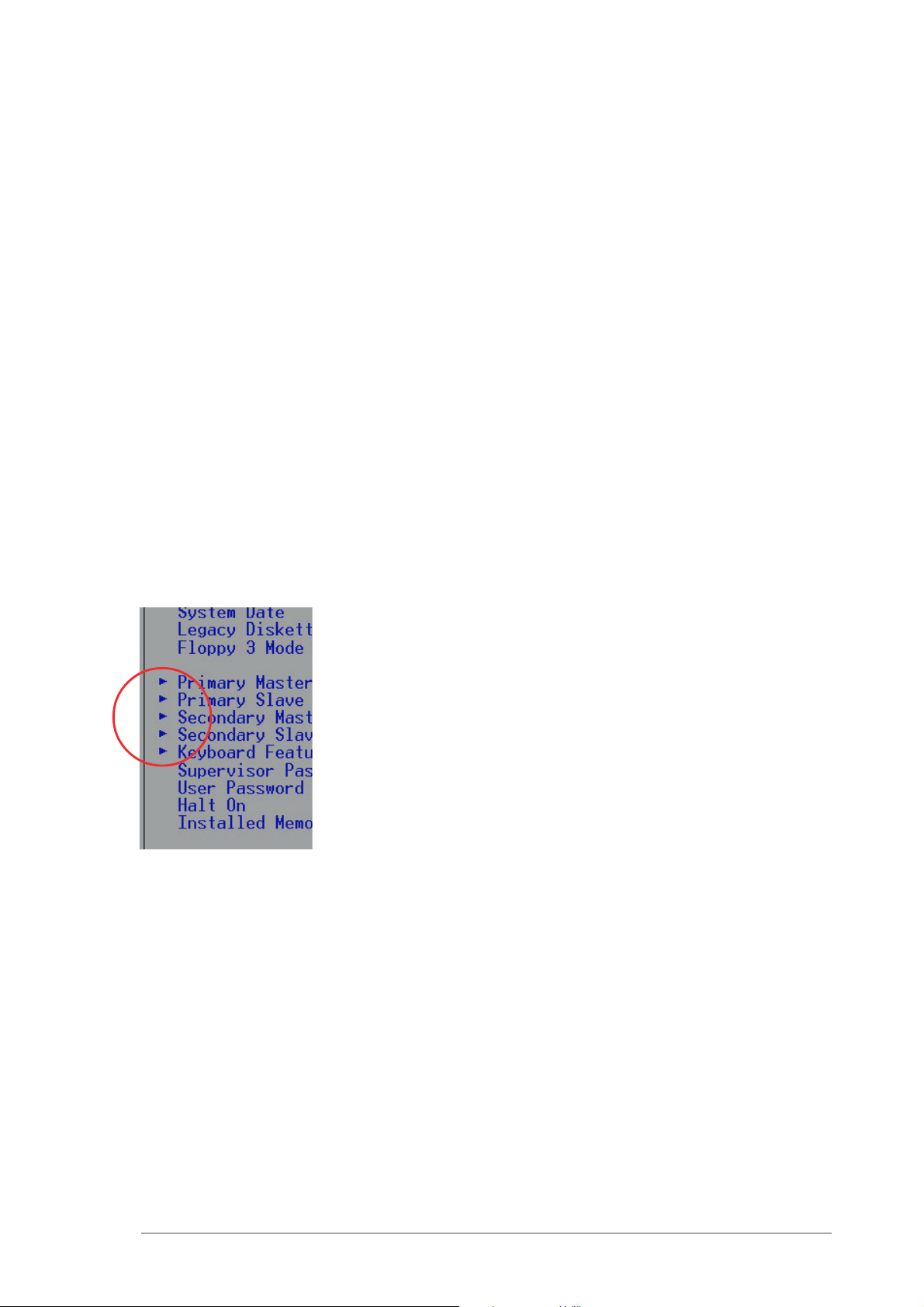
General helpGeneral help
General help
General helpGeneral help
In addition to the Item Specific Help window, the BIOS setup program also
provides a General Help screen. You may launch this screen from any menu
by simply pressing <F1>. The General Help screen lists the legend keys and
their corresponding functions.
Saving changes and exiting the Setup program
See
“4.7 Exit Menu”
the setup program.
Scroll barScroll bar
Scroll bar
Scroll barScroll bar
When a scroll bar appears to the right of a help window, it indicates that
there is more information to be displayed that will not fit in the window.
Use <PgUp> and <PgDn> or the up and down arrow keys to scroll through
the entire help document. Press <Home> to display the first page, press
<End> to go to the last page. To exit the help window, press <Enter> or
<Esc>.
Sub-menuSub-menu
Sub-menu
Sub-menuSub-menu
for detailed information on saving changes and exiting
Note that a right pointer symbol (as shown on the
left) appears to the left of certain fields. This pointer
indicates that you can display a sub-menu from this
field. A sub-menu contains additional options for a
field parameter. To display a sub-menu, move the
highlight to the field and press <Enter>. The submenu appears. Use the legend keys to enter values
and move from field to field within a sub-menu as
you would within a menu. Use the <Esc> key to
return to the main menu.
Take some time to familiarize yourself with the
legend keys and their corresponding functions. Practice navigating through
the various menus and sub-menus. If you accidentally make unwanted
changes to any of the fields, use the set default hot key <F5> to load the
Setup default values. While moving around through the Setup program,
note that explanations appear in the Item Specific Help window located to
the right of each menu. This window displays the help text for the currently
highlighted field.
ASUS K8N4-E DeluxeASUS K8N4-E Deluxe
ASUS K8N4-E Deluxe
ASUS K8N4-E DeluxeASUS K8N4-E Deluxe
4-134-13
4-13
4-134-13
Page 80

4.3 Main Menu
When you enter the Setup program, the following screen appears.
System Time 17:8:12
System Date Wed, Jan 5 2005
Language [English]
Legacy Diskette A [1.44M, 3.5 in.]
Primary IDE Master [ST320410A]
Primary IDE Slave [ASUS CD--S520/]
Secondary IDE Master [None]
Secondary IDE Slave [None]
First SATA Master [None]
Second SATA Master [None]
Third SATA Master [None]
Fourth SATA Master [None]
HDD SMART Monitoring [Disabled]
Installed Memory [256MB]
4.3.14.3.1
4.3.1
4.3.14.3.1
Sets the system to the time that you specify (usually the current time).
The format is hour, minute, second. Valid values for hour, minute and
second are Hour: (00 to 23), Minute: (00 to 59), Second: (00 to 59). Use
the <Tab> key to move between the hour, minute, and second fields.
System Time [xx:xx:xx]System Time [xx:xx:xx]
System Time [xx:xx:xx]
System Time [xx:xx:xx]System Time [xx:xx:xx]
Select Menu
Item Specific Help
Change the internal
clock.
4.3.24.3.2
4.3.2
4.3.24.3.2
Sets the system to the date that you specify (usually the current date).
The format is month, day, year. Valid values for month, day, and year are
Month: (1 to 12), Day: (1 to 31), Year: (up to 2084). Use the <Tab> key
to move between the month, day, and year fields.
4.3.34.3.3
4.3.3
4.3.34.3.3
Allows you to select the language. Configuration options: [English] [French]
[Deutsch]
4.3.44.3.4
4.3.4
4.3.44.3.4
Sets the type of floppy drive installed. Configuration options: [Disabled]
[360K, 5.25 in.] [1.2M , 5.25 in.] [720K , 3.5 in.] [1.44M, 3.5 in.]
[2.88M, 3.5 in.]
System Date [xx/xx/xxxx]System Date [xx/xx/xxxx]
System Date [xx/xx/xxxx]
System Date [xx/xx/xxxx]System Date [xx/xx/xxxx]
Language [English]Language [English]
Language [English]
Language [English]Language [English]
Legacy Diskette A [1.44M, 3.5 in.]Legacy Diskette A [1.44M, 3.5 in.]
Legacy Diskette A [1.44M, 3.5 in.]
Legacy Diskette A [1.44M, 3.5 in.]Legacy Diskette A [1.44M, 3.5 in.]
4-144-14
4-14
4-144-14
Chapter 4: BIOS setupChapter 4: BIOS setup
Chapter 4: BIOS setup
Chapter 4: BIOS setupChapter 4: BIOS setup
Page 81
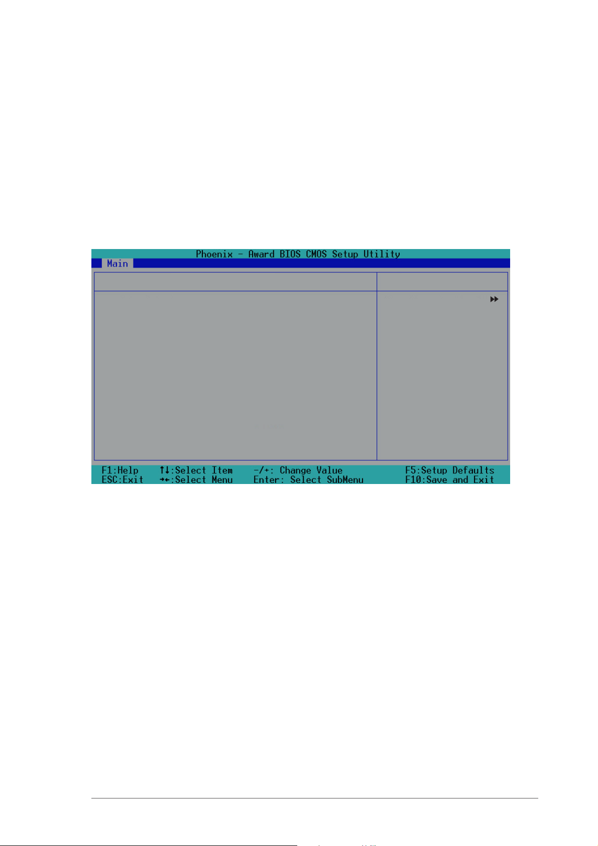
4.3.54.3.5
4.3.5
4.3.54.3.5
Enables or disables Hard Disk SMART capability support.
Configuration options: [Disabled] [Enabled]
HDD SMART Monitoring [Disabled]HDD SMART Monitoring [Disabled]
HDD SMART Monitoring [Disabled]
HDD SMART Monitoring [Disabled]HDD SMART Monitoring [Disabled]
4.3.64.3.6
4.3.6
4.3.64.3.6
This field automatically displays the amount of conventional memory
detected by the system during the boot process.
4.3.74.3.7
4.3.7
4.3.74.3.7
PIO Mode [Auto]
UDMA Mode [Auto]
Primary IDE Master [Auto]
Access Mode [Auto]
Capacity 20021 MB
Cylinder 38792
Head 16
Sector 63
Transfer Mode UDMA 5
Installed Memory [xxx MB]Installed Memory [xxx MB]
Installed Memory [xxx MB]
Installed Memory [xxx MB]Installed Memory [xxx MB]
Primary and Secondary IDE Master/SlavePrimary and Secondary IDE Master/Slave
Primary and Secondary IDE Master/Slave
Primary and Secondary IDE Master/SlavePrimary and Secondary IDE Master/Slave
Primary IDE Master
Select Menu
Item Specific Help
Set a PIO Mode for the
IDE device. Mode0
through 4 successive
increase in
performance.
PIO Mode [Auto]PIO Mode [Auto]
PIO Mode [Auto]
PIO Mode [Auto]PIO Mode [Auto]
This option lets you set a PIO (Programmed Input/Output) mode for the
IDE device. Modes 0 through 4 provide successive increase in performance.
Configuration options: [Auto] [Mode 0] [Mode 1] [Mode 2] [Mode 3]
[Mode 4]
UDMA Mode [Auto]UDMA Mode [Auto]
UDMA Mode [Auto]
UDMA Mode [Auto]UDMA Mode [Auto]
Ultra DMA capability allows improved transfer speeds and data integrity for
compatible IDE devices. Set to [Disabled] to suppress Ultra DMA capability.
Configuration options: [Disabled] [Auto]
ASUS K8N4-E DeluxeASUS K8N4-E Deluxe
ASUS K8N4-E Deluxe
ASUS K8N4-E DeluxeASUS K8N4-E Deluxe
4-154-15
4-15
4-154-15
Page 82

Primary IDE Master [Auto]Primary IDE Master [Auto]
Primary IDE Master [Auto]
Primary IDE Master [Auto]Primary IDE Master [Auto]
Select [Auto] to automatically detect an IDE hard disk drive. If automatic
detection is successful, Setup automatically fills in the correct values for
the remaining fields on this sub-menu. If automatic detection fails, this may
be because the hard disk drive is too old or too new. If the hard disk was
already formatted on an older system, Setup may detect incorrect
parameters. In these cases, select [Manual] to manually enter the IDE hard
disk drive parameters. Refer to the next section for details. Configuration
options: [None] [Auto] [Manual]
Before attempting to configure a hard disk drive, make sure you have
the correct configuration information supplied by the drive
manufacturer. Incorrect settings may cause the system to fail to
recognize the installed hard disk.
Access Mode [Auto]Access Mode [Auto]
Access Mode [Auto]
Access Mode [Auto]Access Mode [Auto]
This item allows the user to select the sector addressing mode. CHS
(cylinder, head, sector) mode supports 528 MB hard disks. LBA (logical
block addressing) mode supports hard disks up to 128 GB in size. Large
mode (also called extended CHS mode) supports hard disks above 528 MB
in size, but does not support LBA mode. Configuration options: [CHS]
[LBA] [Large] [Auto]
CapacityCapacity
Capacity
CapacityCapacity
Displays the auto-detected hard disk capacity. This item is not
configurable.
CylinderCylinder
Cylinder
CylinderCylinder
Shows the number of the hard disk cylinders. This item is not configurable.
HeadHead
Head
HeadHead
Shows the number of the hard disk read/write heads. This item is not
configurable.
SectorSector
Sector
SectorSector
Shows the number of sectors per track. This item is not configurable.
Transfer ModeTransfer Mode
Transfer Mode
Transfer ModeTransfer Mode
Shows the Transfer mode. This item is not configurable.
4-164-16
4-16
4-164-16
Chapter 4: BIOS setupChapter 4: BIOS setup
Chapter 4: BIOS setup
Chapter 4: BIOS setupChapter 4: BIOS setup
Page 83
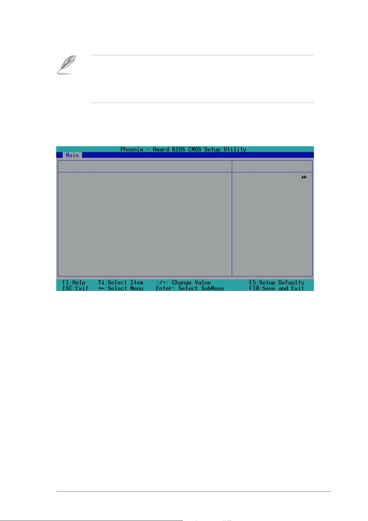
After entering the IDE hard disk drive information into BIOS, use a disk
utility, such as FDISK, to partition and format new IDE hard disk drives.
This is necessary so that you can write or read data from the hard disk.
Make sure to set the partition of the Primary IDE hard disk drives to
active.
4.3.84.3.8
4.3.8
4.3.84.3.8
Extended IDE Drive [Auto]
Access Mode [Auto]
Capacity 0 MB
Cylinder 0
Head 0
Precomp 0
Landing Zone 0
Sector 0
Extended IDE Drive [Auto]Extended IDE Drive [Auto]
Extended IDE Drive [Auto]
Extended IDE Drive [Auto]Extended IDE Drive [Auto]
First, Second, Third, and Fourth SATA MasterFirst, Second, Third, and Fourth SATA Master
First, Second, Third, and Fourth SATA Master
First, Second, Third, and Fourth SATA MasterFirst, Second, Third, and Fourth SATA Master
First SATA Master
Select Menu
Item Specific Help
Selects the type of
fixed disk connected
to the system.
Select [Auto] to automatically detect a SATA hard disk drive. If automatic
detection is successful, Setup automatically fills in the correct values for
the remaining fields on this sub-menu. Configuration options: [None]
[Auto]
Access Mode [Auto]Access Mode [Auto]
Access Mode [Auto]
Access Mode [Auto]Access Mode [Auto]
Allows the user to select the sector addressing mode. Refer to the
previous page for detailed descriptions of the different modes.
Configuration options: [Large] [Auto]
CapacityCapacity
Capacity
CapacityCapacity
Displays the auto-detected hard disk capacity. This item is not
configurable.
CylinderCylinder
Cylinder
CylinderCylinder
Shows the number of the hard disk cylinders. This item is not configurable.
ASUS K8N4-E DeluxeASUS K8N4-E Deluxe
ASUS K8N4-E Deluxe
ASUS K8N4-E DeluxeASUS K8N4-E Deluxe
4-174-17
4-17
4-174-17
Page 84

HeadHead
Head
HeadHead
Shows the number of the hard disk read/write heads. This item is not
configurable.
PrecompPrecomp
Precomp
PrecompPrecomp
Shows the number of precomp per track. This item is not configurable.
Landing ZoneLanding Zone
Landing Zone
Landing ZoneLanding Zone
Shows the number of landing zone per track. This item is not configurable.
SectorSector
Sector
SectorSector
Shows the number of sectors per track. This item is not configurable.
After entering the IDE hard disk drive information into BIOS, use a disk
utility, such as FDISK, to partition and format new IDE hard disk drives.
This is necessary so that you can write or read data from the hard disk.
Make sure to set the partition of the Primary IDE hard disk drives to
active.
4-184-18
4-18
4-184-18
Chapter 4: BIOS setupChapter 4: BIOS setup
Chapter 4: BIOS setup
Chapter 4: BIOS setupChapter 4: BIOS setup
Page 85

4.4 Advanced Menu
The Advanced menu items allow you to change the settings for the CPU
and other system devices.
Take caution when changing the settings of the Advanced menu items.
Incorrect field values may cause the system to malfunction.
CPU Configuration
PCIPnP
Onboard Device Configuration
JumperFree Configuration
LAN Cable Status
PEG Link Mode
Speech Configuration
Instant Music
Select Menu
Item Specific Help
Press Enter to Set.
ASUS K8N4-E DeluxeASUS K8N4-E Deluxe
ASUS K8N4-E Deluxe
ASUS K8N4-E DeluxeASUS K8N4-E Deluxe
4-194-19
4-19
4-194-19
Page 86
4.4.14.4.1
4.4.1
4.4.14.4.1
CPU configurationCPU configuration
CPU configuration
CPU configurationCPU configuration
The items in this menu show the CPU-related information auto-detected by
the BIOS.
CPU Configuration
CPU Type AMD Athlon(tm) 64 Processor 3200+
CPU Speed 2000MHz
Cache RAM 1024K
DRAM Configuration
Hyper Transport Frequency [4x]
AMD K8 Cool ‘n’ Quiet control [Enabled]
DRAM ConfigurationDRAM Configuration
DRAM Configuration
DRAM ConfigurationDRAM Configuration
Select Menu
Item Specific Help
The items in this sub-menu show the DRAM-related information that the
BIOS auto-detects.
DRAM Configuration
Timing Mode [Auto]
Memclock Index Value (MHz) [100MHz]
CAS# Latency (Tcl) [2.5]
Min RAS# active time (Tras) [8T]
RAS# to CAS# delay (Trcd) [4T]
Row precharge time (Trp) [4T]
1T/2T Memory Timing [2T]
Master ECC Enable [Disabled]
Select Menu
Item Specific Help
Places an artificial
memory clock limit
on the system.
Memory is prevented
from running faster
than this frequency.
4-204-20
4-20
4-204-20
Chapter 4: BIOS setupChapter 4: BIOS setup
Chapter 4: BIOS setup
Chapter 4: BIOS setupChapter 4: BIOS setup
Page 87

Timing Mode [Auto]
Sets the timing mode.
Configuration options: [Auto] [Manual]
Memclock Index Value (MHz) [100MHz]
Sets the maximum operating memory clock.
Configuration options: [100MHz] [133MHz] [166MHz] [200MHz]
CAS# latency (Tcl) [2.5]
Sets the CAS# latency, which is the CAS # to read valid data.
Configuration options: [2.0] [2.5] [3.0]
Min RAS# active time (Tras) [8T]
Sets the minimum RAS# active time.
Configuration options: [5] [6] [7] [8] [9] [10] [11] [12] [13] [14]
[15]
RAS# to CAS# delay (Trcd) [4T]
Sets the RAS# to CAS# delay to Read/Write command on the same
bank. Configuration options: [2] [3] [4] [5] [6] [7]
Row precharge Time (Trp) [4T]
Sets the Row precharge time. Precharge to Active or Auto-Refresh of
the same bank. Configuration options: [2] [3] [4] [5] [6]
1T/2T Memory Timing [2T]
Sets the memory timing. Configuration options: [1T] [2T]
Master ECC Enable [Disabled]
Enables or disables the master ECC function.
Configuration options: [Disabled] [Enabled]
Hyper Transport Frequency [4x]Hyper Transport Frequency [4x]
Hyper Transport Frequency [4x]
Hyper Transport Frequency [4x]Hyper Transport Frequency [4x]
Sets the Hyper Transport frequency.
Configuration options: [1x] [2x] [3x] [4x]
AMD K8 Cool ‘n’ Quiet control [Enabled]AMD K8 Cool ‘n’ Quiet control [Enabled]
AMD K8 Cool ‘n’ Quiet control [Enabled]
AMD K8 Cool ‘n’ Quiet control [Enabled]AMD K8 Cool ‘n’ Quiet control [Enabled]
Enables or disables the AMD K8 Cool ‘n’ Quiet!™ technology.
Configuration options: [Disabled] [Enabled]
ASUS K8N4-E DeluxeASUS K8N4-E Deluxe
ASUS K8N4-E Deluxe
ASUS K8N4-E DeluxeASUS K8N4-E Deluxe
4-214-21
4-21
4-214-21
Page 88

4.4.24.4.2
4.4.2
4.4.24.4.2
PCIPnPPCIPnP
PCIPnP
PCIPnPPCIPnP
The items in this menu show the PCIPnP configuration settings. Select an
item then press <Enter> to display a pop-up menu with the configuration
options.
PCIPnP
Plug & Play O/S [No]
Init Display First [PCI Slot]
Resources Controlled By [Auto]
x IRQ Resources
PCI/VGA Palette Snoop [Disabled]
Plug & Play OS [No]Plug & Play OS [No]
Plug & Play OS [No]
Plug & Play OS [No]Plug & Play OS [No]
Select Menu
Item Specific Help
Select Yes if you
are using a Plug and
Play capable system.
Select No if you
need the BIOS to
configure non-boot
devices.
When set to [No], the BIOS configures all the devices in the system. When
set to [Yes] and if you install a Plug and Play operating system, the
operating system configures the Plug and Play devices not required for
boot. Configuration options: [No] [Yes]
Init Display First [PCI Slot]Init Display First [PCI Slot]
Init Display First [PCI Slot]
Init Display First [PCI Slot]Init Display First [PCI Slot]
Allows you to select which graphics controller to use as the primary boot
device. Configuration options: [PCI slot] [PCIEx]
Resources Controlled By [Auto]Resources Controlled By [Auto]
Resources Controlled By [Auto]
Resources Controlled By [Auto]Resources Controlled By [Auto]
When set to [Auto], the BIOS automatically configures all the boot and
Plug and Play devices. Set to [Manual] if you want to assign the IRQ DMA
and memory base address fields. Configuration options: [Auto] [Manual]
Resources Controlled ByResources Controlled By
Resources Controlled By is set to [Auto], the item
Resources Controlled ByResources Controlled By
Chapter 4: BIOS setupChapter 4: BIOS setup
Chapter 4: BIOS setup
Chapter 4: BIOS setupChapter 4: BIOS setup
4-224-22
4-22
4-224-22
When the item
IRQ Resources is grayed out and is not user-configurable. Refer to the
section “IRQ Resources” for information on how to enable this item.
Page 89
IRQ ResourcesIRQ Resources
IRQ Resources
IRQ ResourcesIRQ Resources
IRQ Resources
IRQ-3 assigned to [PCI Device]
IRQ-5 assigned to [PCI Device]
IRQ-7 assigned to [PCI Device]
IRQ-9 assigned to [PCI Device]
IRQ-10 assigned to [PCI Device]
IRQ-11 assigned to [PCI Device]
IRQ-12 assigned to [PCI Device]
IRQ-14 assigned to [PCI Device]
IRQ-15 assigned to [PCI Device]
Select Menu
Item Specific Help
Legacy ISA for devices
compliant with the
orginal PC AT bus
specification, PCI/ISA
PnP for devices
compliant with the Plug
and Play Standard
whether designed for
PCI or ISA bus
architecture.
IRQ-xx assigned to
When set to [PCI Device], the specific IRQ is free for use of PCI/PnP
devices. When set to [Reserved], the IRQ is reserved for legacy ISA
devices. Configuration options: [PCI Device] [Reserved]
PCI/VGA Palette Snoop [Disabled]PCI/VGA Palette Snoop [Disabled]
PCI/VGA Palette Snoop [Disabled]
PCI/VGA Palette Snoop [Disabled]PCI/VGA Palette Snoop [Disabled]
When set to [Enabled], the palette snooping feature informs the PCI
devices that an ISA graphics device is installed in the system so that the
latter can function correctly. Configuration options: [Disabled] [Enabled]
ASUS K8N4-E DeluxeASUS K8N4-E Deluxe
ASUS K8N4-E Deluxe
ASUS K8N4-E DeluxeASUS K8N4-E Deluxe
4-234-23
4-23
4-234-23
Page 90

4.4.34.4.3
4.4.3
4.4.34.4.3
Onboard device configuration Onboard device configuration
Onboard device configuration
Onboard device configuration Onboard device configuration
The items in this menu show the onboard device configuration settings.
Select an item then press <Enter> to display a pop-up menu with the
configuration options.
Onboard Device Configuration
IDE Function Setup
NVRAID Configuration
USB Configuration
Onboard 1394 [Enabled]
Onboard Giga LAN [Enabled]
Onboard LAN Boot ROM [Disabled]
AC97 Audio [Enabled]
Silicon SATA Controller [Enabled]
Serial Port 1 Address [3F8/IRQ4]
Parallel Port Address [378/IRQ7]
Parallel Port Mode [ECP+EPP]
ECP Mode Use DMA [3]
Game Port Address [201]
Midi Port Address [330]
Midi Port IRQ 10
IDE Function SetupIDE Function Setup
IDE Function Setup
IDE Function SetupIDE Function Setup
Select Menu
Item Specific Help
This sub-menu contains IDE function-related items. Select an item then
press <Enter> to edit.
4-244-24
4-24
4-244-24
IDE Function Setup
OnChip Channel0 [Enabled]
OnChip IDE Channel1 [Enabled]
IDE DMA transfer access [Enabled]
SATA Port 1, 2 [Enabled]
SATA DMA transfer [Enabled]
SATA Port 3, 4 [Enabled]
SATA2 DMA transfer [Enabled]
IDE Prefetch Mode [Enabled]
Select Menu
Item Specific Help
Chapter 4: BIOS setupChapter 4: BIOS setup
Chapter 4: BIOS setup
Chapter 4: BIOS setupChapter 4: BIOS setup
Page 91

OnChip IDE Channel0 [Enabled]
Allows you to enable or disable the onchip IDE channel 0 controller .
Configuration options: [Disabled] [Enabled]
OnChip IDE Channel1 [Enabled]
Allows you to enable or disable the onchip IDE channel 1 controller .
Configuration options: [Disabled] [Enabled]
IDE DMA transfer access [Enabled]
Allows you to enable or disable the IDE DMA transfer access.
Configuration options: [Disabled] [Enabled]
SATA Port 1,2 [Enabled]
Allows you to enable or disable the SATA 1 and 2 ports.
Configuration options: [Disabled] [Enabled]
SATA DMA transfer [Enabled]
Allows you to enable or disable the SATA DMA transfer access.
Configuration options: [Disabled] [Enabled]
SATA Port 3, 4 [Enabled]
Allows you to enable or disable the SATA 3 and 4 ports.
Configuration options: [Disabled] [Enabled]
SATA2 DMA transfer [Enabled]
Allows you to enable or disable the SATA2 DMA transfer access.
Configuration options: [Disabled] [Enabled]
IDE Prefetch Mode [Enabled]
Allows you to enable or disable the IDE prefetch mode.
Configuration options: [Disabled] [Enabled]
ASUS K8N4-E DeluxeASUS K8N4-E Deluxe
ASUS K8N4-E Deluxe
ASUS K8N4-E DeluxeASUS K8N4-E Deluxe
4-254-25
4-25
4-254-25
Page 92

NVRAID ConfigurationNVRAID Configuration
NVRAID Configuration
NVRAID ConfigurationNVRAID Configuration
This sub-menu contains NVRAID function-related items. Select an item then
press <Enter> to edit.
NVRAID Configuration
RAID Enable [Disabled]
x IDE Primary Master RAID Disabled
x IDE Primary Slave RAID Disabled
x IDE Secondary Master RAID Disabled
x IDE Secondary Slave RAID Disabled
x First SATA Master RAID Disabled
x Second SATA Master RAID Disabled
x Third SATA Master RAID Disabled
x Fourth SATA Master RAID Disabled
RAID Enable [Disabled]
Enables or disables the onboard RAID controller.
Configuration options: [Enabled] [Disabled]
Select Menu
Item Specific Help
The following items become user-configurable when the
item is set to [Enabled].
RAID EnableRAID Enable
RAID Enable
RAID EnableRAID Enable
IDE Primary and Secondary Master/Slave RAID [Disabled]
Enables or disables the RAID function of the primary or secondary
master or slave IDE. Configuration options: [Enabled] [Disabled]
First, Second, Third, Fourth SATA Master RAID [Disabled]
Enables or disables the RAID function of the first, second, third, or
fourth SATA master drive. Configuration options: [Enabled] [Disabled]
4-264-26
4-26
4-264-26
Chapter 4: BIOS setupChapter 4: BIOS setup
Chapter 4: BIOS setup
Chapter 4: BIOS setupChapter 4: BIOS setup
Page 93

USB configurationUSB configuration
USB configuration
USB configurationUSB configuration
The items in this menu show the USB configuration settings. Select an item
then press <Enter> to display a pop-up menu with the configuration
options.
USB Configuration
USB Controller [Enabled]
USB 2.0 Controller [Enabled]
USB Legacy Support [Enabled]
Select Menu
Item Specific Help
USB Controller [Enabled]
Allows you to enable or disable the onchip USB controller.
Configuration options: [Disabled] [Enabled]
USB 2.0 Controller [Enabled]
Allows you to enable or disable the USB 2.0 controller.
Configuration options: [Disabled] [Enabled]
USB Legacy Support [Enabled]
Allows you to enable or disable support for USB devices on legacy
operating systems (OS). Configuration options: [Disabled] [Enabled]
ASUS K8N4-E DeluxeASUS K8N4-E Deluxe
ASUS K8N4-E Deluxe
ASUS K8N4-E DeluxeASUS K8N4-E Deluxe
4-274-27
4-27
4-274-27
Page 94

Onboard 1394 [Enabled]Onboard 1394 [Enabled]
Onboard 1394 [Enabled]
Onboard 1394 [Enabled]Onboard 1394 [Enabled]
Allows you to enable or disable the onboard IEEE 1394a device support.
Configuration options: [Disabled] [Enabled]
Onboard Giga LAN [Enabled]Onboard Giga LAN [Enabled]
Onboard Giga LAN [Enabled]
Onboard Giga LAN [Enabled]Onboard Giga LAN [Enabled]
Allows you to enable or disable the onboard NVDIA
Configuration options: [Disabled] [Enabled]
Onboard LAN Boot ROM [Disabled]Onboard LAN Boot ROM [Disabled]
Onboard LAN Boot ROM [Disabled]
Onboard LAN Boot ROM [Disabled]Onboard LAN Boot ROM [Disabled]
Allows you to enable or disable the boot ROM of the onboard LAN chip.
Configuration options: [Enabled] [Disabled]
AC97 Audio [Enabled]AC97 Audio [Enabled]
AC97 Audio [Enabled]
AC97 Audio [Enabled]AC97 Audio [Enabled]
Allows you to enable or disable the onboard AC`97 Audio controller.
Configuration options: [Disabled] [Enabled]
Silicon SATA Controller [Enabled]Silicon SATA Controller [Enabled]
Silicon SATA Controller [Enabled]
Silicon SATA Controller [Enabled]Silicon SATA Controller [Enabled]
Allows you to enable or disable the onboard Silicon Image RAID controller.
Configuration options: [Disabled] [Enabled]
®
Gigabit LAN controller.
Serial Port1 Address [3F8/IRQ4]Serial Port1 Address [3F8/IRQ4]
Serial Port1 Address [3F8/IRQ4]
Serial Port1 Address [3F8/IRQ4]Serial Port1 Address [3F8/IRQ4]
Allows you to select the Serial Port1 base address.
Configuration options: [Disabled] [3F8/IRQ4] [2F8/IRQ3] [3E8/IRQ4]
[2E8/IRQ3]
Parallel Port Address [378/IRQ7]Parallel Port Address [378/IRQ7]
Parallel Port Address [378/IRQ7]
Parallel Port Address [378/IRQ7]Parallel Port Address [378/IRQ7]
Allows you to select the Parallel Port base addresses.
Configuration options: [Disabled] [378/IRQ7] [278/IRQ5] [3BC/IRQ7]
Parallel Port Mode [ECP+EPP]Parallel Port Mode [ECP+EPP]
Parallel Port Mode [ECP+EPP]
Parallel Port Mode [ECP+EPP]Parallel Port Mode [ECP+EPP]
Allows you to select the Parallel Port mode.
Configuration options: [SPP] [EPP] [ECP] [ECP+EPP]
ECP Mode Use DMA [3]ECP Mode Use DMA [3]
ECP Mode Use DMA [3]
ECP Mode Use DMA [3]ECP Mode Use DMA [3]
Allows you to select the ECP Mode. This item becomes configurable only if
Parallel Port ModeParallel Port Mode
the
Parallel Port Mode is set to [ECP] or [ECP+EPP]. Configuration
Parallel Port ModeParallel Port Mode
options: [1] [3]
4-284-28
4-28
4-284-28
Chapter 4: BIOS setupChapter 4: BIOS setup
Chapter 4: BIOS setup
Chapter 4: BIOS setupChapter 4: BIOS setup
Page 95

Game Port Address [201]Game Port Address [201]
Game Port Address [201]
Game Port Address [201]Game Port Address [201]
Allows you to select the Game port address or to disable the port.
Configuration options: [Disabled] [201] [209]
Midi Port Address [330]Midi Port Address [330]
Midi Port Address [330]
Midi Port Address [330]Midi Port Address [330]
Allows you to select the MIDI port address or to disable the port.
Configuration options: [Disabled] [330] [300]
Midi Port IRQ [10]Midi Port IRQ [10]
Midi Port IRQ [10]
Midi Port IRQ [10]Midi Port IRQ [10]
Allows you to set the Midi port IRQ address. This item becomes
configurable only if the
Configuration options: [5] [10]
Midi Port AddressMidi Port Address
Midi Port Address item is set to [300] or [330]
Midi Port AddressMidi Port Address
ASUS K8N4-E DeluxeASUS K8N4-E Deluxe
ASUS K8N4-E Deluxe
ASUS K8N4-E DeluxeASUS K8N4-E Deluxe
4-294-29
4-29
4-294-29
Page 96
4.4.44.4.4
4.4.4
4.4.44.4.4
JumperFree ConfigurationJumperFree Configuration
JumperFree Configuration
JumperFree ConfigurationJumperFree Configuration
JumperFree Configuration
Overclock Profile [Auto]
x Overclock Options Disabled
x CPU Frequency 200.00
x PCI Express Clock 100MHz
x DDR Voltage Auto
x CPU Multiplier Auto
Overclock Profile [Auto]Overclock Profile [Auto]
Overclock Profile [Auto]
Overclock Profile [Auto]Overclock Profile [Auto]
Select Menu
Item Specific Help
Allows selection of CPU overclocking options to achieve desired CPU
internal frequency. Select either one of the preset overclocking
configuration options:
ManualManual
Manual Allows you to individually set overclocking parameters.
ManualManual
AutoAuto
Auto Loads the optimal settings for the system.
AutoAuto
StandardStandard
Standard Loads the standard settings for the system.
StandardStandard
AI OverclockAI Overclock
A I O v e r c l o c k Loads overclocking profiles with optimal parameters for stability
AI OverclockAI Overclock
when overclocking.
4-304-30
4-30
4-304-30
Chapter 4: BIOS setupChapter 4: BIOS setup
Chapter 4: BIOS setup
Chapter 4: BIOS setupChapter 4: BIOS setup
Page 97

The following items are user-configurable only when the Overclock
Profile item is set to [Manual].
CPU Frequency [XXX] (value is auto-detected)CPU Frequency [XXX] (value is auto-detected)
CPU Frequency [XXX] (value is auto-detected)
CPU Frequency [XXX] (value is auto-detected)CPU Frequency [XXX] (value is auto-detected)
Indicates the frequency sent by the clock generator to the system bus and
PCI bus. The bus frequency (external frequency) multiplied by the bus
multiple equals the CPU speed. The value of this item is auto-detected by
BIOS. The values range from 200 to 400. Refer to the following table for
the correct Front Side Bus and CPU External Frequency settings.
Selecting a very high CPU frequency may cause the system to become
unstable! If this happens, revert to the default setting.
PCI Express Clock [100MHz]PCI Express Clock [100MHz]
PCI Express Clock [100MHz]
PCI Express Clock [100MHz]PCI Express Clock [100MHz]
Allows you to set the PCI Express clock. Key-in a decimal value between
100-200 MHz. Configuration options: [100Mhz] [101Mhz~[145Mhz]
DDR Voltage [Auto]DDR Voltage [Auto]
DDR Voltage [Auto]
DDR Voltage [Auto]DDR Voltage [Auto]
Sets the operating DDR voltage. Configuration options: [Auto] [2.60V]
[2.65V] [2.70V] [2.75V] [2.80V] [2.85V] [2.90V] [2.95V] [3.00V]
CPU Multiplier [Auto]CPU Multiplier [Auto]
CPU Multiplier [Auto]
CPU Multiplier [Auto]CPU Multiplier [Auto]
Sets the operating CPU multiplier. The configuration options vary
depending on the type of CPU installed. Configuration options: [Auto] [x4]
[x4.5] [x5] [x5.5] [x6] [x6.5] [x7] [x7.5] [x7.5] [x8] [x8.5] [x9] [x9.5]
[x10] [x10.5] [x11] [x11.5] [x12] [x12.5] [x13] [x13.5] [x14] [x14.5]
[x15] [x15.5] [x16] [x16.5] [x17] [x17.5] [x18] [x18.5] [x19] [x19.5]
[x20]
ASUS K8N4-E DeluxeASUS K8N4-E Deluxe
ASUS K8N4-E Deluxe
ASUS K8N4-E DeluxeASUS K8N4-E Deluxe
4-314-31
4-31
4-314-31
Page 98

The following item is user-configurable only when the AI Overclocking
item is set to [AI Overclock].
Overclock Options [Disabled]Overclock Options [Disabled]
Overclock Options [Disabled]
Overclock Options [Disabled]Overclock Options [Disabled]
Allows you to set the oveclocking options.
Configuration options: [Disabled] [Overclock 3%] [Overclock 5%]
[Overclock 8%] [Overclock 10%]
4.4.54.4.5
4.4.5
4.4.54.4.5
The items in this menu displays the status of the Local Area Network
(LAN) cable.
LAN Cable StatusLAN Cable Status
LAN Cable Status
LAN Cable StatusLAN Cable Status
LAN Cable Status
POST Check LAN Cable [Disabled]
Pair Status Length
1-2 Open N/A
3-6 Open N/A
4-5 Open N/A
7-8 Open N/A
Select Menu
Item Specific Help
POST Check LAN cable [Disabled]POST Check LAN cable [Disabled]
POST Check LAN cable [Disabled]
POST Check LAN cable [Disabled]POST Check LAN cable [Disabled]
Enables or disables checking of the LAN cable during the Power-On
Self-Test (POST). Configuration options: [Disabled] [Enabled]
4-324-32
4-32
4-324-32
Chapter 4: BIOS setupChapter 4: BIOS setup
Chapter 4: BIOS setup
Chapter 4: BIOS setupChapter 4: BIOS setup
Page 99
4.4.64.4.6
4.4.6
4.4.64.4.6
PEG Link ModePEG Link Mode
PEG Link Mode
PEG Link ModePEG Link Mode
PEG Link Mode
PEG Link Mode [Auto]
PEG Root Control [Auto]
PEG Buffer Length [Auto]
PEG Link Mode [Auto]PEG Link Mode [Auto]
PEG Link Mode [Auto]
PEG Link Mode [Auto]PEG Link Mode [Auto]
Allows you to enhance the performance of your PCI Express graphics card.
Configuration options: [Auto] [Disabled] [Normal] [Fast] [Faster]
Select Menu
Item Specific Help
Enhance performance
on PCIE serial
graphic card
PEG Root Control [Auto]PEG Root Control [Auto]
PEG Root Control [Auto]
PEG Root Control [Auto]PEG Root Control [Auto]
Allows you to enable or disable the PCI Express graphics root control.
Configuration options: [Auto] [Enabled] [Disabled]
PEG Buffer Length [Auto]PEG Buffer Length [Auto]
PEG Buffer Length [Auto]
PEG Buffer Length [Auto]PEG Buffer Length [Auto]
Allows you to set the PCI Express graphics buffer length.
Configuration options: [Auto] [Long] [Short]
ASUS K8N4-E DeluxeASUS K8N4-E Deluxe
ASUS K8N4-E Deluxe
ASUS K8N4-E DeluxeASUS K8N4-E Deluxe
4-334-33
4-33
4-334-33
Page 100

4.4.74.4.7
4.4.7
4.4.74.4.7
Speech ConfigurationSpeech Configuration
Speech Configuration
Speech ConfigurationSpeech Configuration
Speech Configuration
Speech IC Reporter [Enabled]
Report IDE Error [Disabled]
Report System Booting [Disabled]
Speech IC Reporter [Enabled]Speech IC Reporter [Enabled]
Speech IC Reporter [Enabled]
Speech IC Reporter [Enabled]Speech IC Reporter [Enabled]
Allows you to enable or disable the ASUS POST Reporter™ feature.
Configuration options: [Disabled] [Enabled]
Select Menu
Item Specific Help
The following items are user-configurable only when the item
IC Reporter IC Reporter
IC Reporter is set to [Enabled].
IC Reporter IC Reporter
Report IDE Error [Disabled]Report IDE Error [Disabled]
Report IDE Error [Disabled]
Report IDE Error [Disabled]Report IDE Error [Disabled]
Allows you to enable or disable the report feature in the event of an IDE
error. Configuration options: [Disabled] [Enabled]
Report System Booting [Disabled]Report System Booting [Disabled]
Report System Booting [Disabled]
Report System Booting [Disabled]Report System Booting [Disabled]
Allows you to enable or disable the report after booting the system.
Configuration options: [Disabled] [Enabled]
SpeechSpeech
Speech
SpeechSpeech
4-344-34
4-34
4-344-34
Chapter 4: BIOS setupChapter 4: BIOS setup
Chapter 4: BIOS setup
Chapter 4: BIOS setupChapter 4: BIOS setup
 Loading...