

Page 1

P/I-P6RP4
PCI/lSA/MecliaBus, 150/166 /¡HO/20
Pentium Pm Processor Mainhoan! •
With Super Multi-I/O
Page 2

III. INSTALLATION
Installation Procedures
|. Sel Jufopcrs on the Molberhoand
2. tnsiiill OkAM Modules
3. InstiiJltlieCPLIanilVRM
4. fnstall ExpansionCfinds
5. Conned EMernal Cables snd Wires
6. Soltip [he RIOS Software
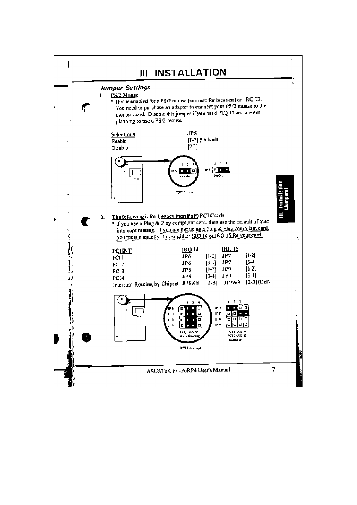
1. Jumpers
SrkXTill hiirdwart stllilies are made thrutiBji (Iw use of jum|KT enps lo con
nect jumper pins fJP) on (Ite motherboard, (Please see the motherboard
diagriitnfbrIocatioilSofiliEjumpHrs.jThejunipersscttingswiillibedescribccI
immej lea lly itlth ns [ =— ], [ I -2 ], [2-j ] for no connet [ loh, connect p ins I it -.
and connect pins 2 & 3 re.'tpeciivdy. Pin I tbrourmothertoancls li; always On
Л
top
the Veyboacd connectorflway from yourself. Thcjumger^^ll also be show n
graphically aOohasOff . to connect pins I 4:2 and Ito connect pins
2 43, For manufacturing simplicity, the junipers may be sJiann^pins from
Ollier groups. Use the diagrams in this msuiua! irtstead ot foUowin^ the pin
layout on the board.
Settings with JwD jumper numbers require two jumper caps to be moved
tdgcihcr. Settings In bold face represent default settings. To connect t!ie
pins, simply place a p last! c j umpe г cap о vet th c two pins us needed. du m per
pins without connection numbers arc exicrnal connectors fur LEDs oi
switches, noi for jumper cups.
CAUTION: Computer mo therbaords and coiuipotients contain very delicate
IC diips. To protect llie tnoiherbourd and uliter components against dam
age fioni ittaUc electric, you should follow some precauiinits wherever yim
wmk on your computer:
Oí on the left “¡when holding the motherboard wjih
UnplU|t your cmiiputcf when working on the inside
I lold componetiis by the edges and try not to touch liie 1C chips.
Use a ¡you tided w-risi Sirup before hand ling conipuier tomponenisPlace components on a grounded antistatic pad or tlie bug that came
with iht! component wherttíver you work on tliem uutside the conipuier,
ASUSTeK P.''I-P6RI>4 User's Munual
e
■ 1
Page 3
Page 4
Page 5
Page 6
Page 7

Page 8
Page 9

Page 10

Page 11

Page 12

Page 13

IPI. INSTALLATION
4. Expansion Cards
Pirst read youi' ei(pans]on card dociiffleniiiMoii cm atiy liardware and softwire settings that ma> be required.
NOTL: I'd I slot d has an e^tonsion for a Medianus card (opti-orel mullifoncfion card)ltiai cflr only allcnv the instflllatioii ofa PCI card ora MediaBinr
card but not both.
finpartsitm Card [nsfallatron I’rocedurasi
Itcad docuTneiitjiEion for your espansion card.
Set any necessary jinn pets on your eKjiaiiaiijn caid.
j.
Unscrew your computer's Case,
4.
ftoscrew the slot-cover for the slot wu want to use,
i
CatefutJy aligji the card's connectors and press firmly.
6.
Screw the card's mounting bracket to the case,
1
tltose the case.
5.
Setup (tic computer's BIOS if necessary,
Ч.
Install necessary software drivtirE for your expansion card
Assigning ERQii for Expan.xton Cards
Some fïKpansion cards need to use an IRQ to operate. Generally an IRQ
must he exclusively assigned to one use. Irt an standard design there are 1$
IRQs available but some of them are already in use by parts of the sysictn
such as the keyboard or mouse. Expansion cards (ha( rtced to use an [RQ
then draw from the unused group of System iRQs.
Both rSA atid PCI expEinston cards may need to use IRQs. Syatera IRQs ate
svaiJablc to cards installed in Ihe ISAcxparsiori bus first, and any rtonainin^
IRQs Etre ihen used by PCI cards. Cumrntiy. there are iwo types of ISA
cards. The original ISA expaoEior card design, now referred to as "Legacy"
I SA cards, m(\ u i res th at you con figure the card's j umpers marua I ly and then
install it in any available slot or the ISA bus, You may use Microsoft’s
Oiagnostic (MSD.EXE) utility included in [he Witidows dinecTory to see a
map of yunr used and free IRQs, Make sure that no two devices use the
same IRQs or your computer will experience problems wheir ihosc two du-
VCÜCS are in use at the samt lime.
To ùmplilÿ this process our motherboards have complied with the Plug and
Play fPNPi sfKcincation which was developed to allow automatic system
eunfiguration whenever ,i PNP-cornpliant card is added to the systcin For
PNP cards, JRQs arc assigned autornaticaJly froiti those avail^b]^
ASlJSfeR P.'l-PfakP4 User's
14 I
Page 14

INSTALLATION
If rhc svsicrn liai both Ncgacy and PNP ISA caids insta I led. iRQs stí eis-
sii^ned til PNP cardi from those not used by I.egaey cards. If you have an
ISA configurdtion utilily (TCU), you can use it to indicate whieli IRQs are in
use by Legacy cards. 11‘you do not have an ICU program, you can use tiie
PCI and PNP configuration of ihc BIOS setup utility to indicate which IRQs
.ire being used by Legacy cards,
,An IRQ number is automatically assigned tc PCI e\p3nsicu] cards slier those
used by iHCgacy and PNP ISA cards. In Lbe PCI bus design, the BIOS auto
matically assigns an IRQ to a PCI slot that has a card in it that requires an
IRQ To install a PCI card, you need to set something called the iK f {inteirtipt) assignment. Since all the PCi slots on this motherboard use an INTA
N, be sure that the jumpers on ydut PCI cards are set lo INT A,
Assigning DMA Channels for TSA Cards
Some ISA cards, both legacy and PNP may also need to use a DMA (Direct
Memory Access) channel. DMA assignments for this riiotherboard uiu
handled the same way as the IRQ assignment process described above. If
veu don't use an ICU program, ycu cati also select a DMA channei in the
PCI and PNI' conliguratioti section of lite BIOS Setup utility.
5. External Connectors
The connectors on the motherboard is simiiar to that of jumper pins. The
CPl.f Processing speed is regulated internally and iherelbre the Turbo Switch
is not supported. Noie: Ribbon cables should always be connected with the
red stripe on the Pin 1 side of the co tin eu tor. The rourconiersofthecoiiiiectors are labeled on the motherboard. Pin 1 is the side closest to the power
connector oil Jiard drives and floppy drives. Note: IDE ribbon cable must
be less than I Bin. f46cm), with ihe second drive connector no more iJian tìio,
H5cm) from the first Cdiineetor,
I) Keyboard Connector (S Pia Female Plug)
Cofinectioii for Ü standard IBM-compatible keyboard May be known
asa Itti enhanced kuyhourd
-1
kl-'iliiÉiil fill
Page 15

Page 16

Page 17

Page 18

Page 19

Page 20

Page 21

Page 22

Page 23

IV. BIOS SETUP
DcycripZ/fj/i of Disk Parameters
T\|H‘ The number for a drive vviih tertair identi Heat ion parameters
C_tI {Cylindc rs) The TLimber of cylinders in the disk drive
Hd f Heads) The jiLtnber of heads
WP (Write Precompensation) The size of a sector gets progressively
smaller as the track diameter dimimshes. Yet each sector stilt holds ii 12
bytes. Wnte precompensation eircuttry on the hard disk compensates for
the physical difiiirente in sector size by boosting the write current for scclore 00 iniicr tracks. This parameter ¡3 (he track number where write pre
compensation begins.
LZ (l..andingZone) This number is the cylinder location where the heads
will nofmally park when the system is shut down.
Sec (Sectors) The number of secfors peMrack. MFM drives have 17
sectors per track. RLL drives have 26 sectors per track. ESHI drives have
34 sectors pir track. SCSI and lilt! drives may have even more sectors per
track.
Size The formatted capacity of the drive ii (Number of Heads} .i; (Num
r
J!
y
ber of Cylinders) X (Number of Sectors per Track) x (5 I2 bytes per Sector)
Using auto detect hard dhh {onty for IDE drives)
If yon select IDE Setup ffom the Utility section of die BIOS Setup main
menu, the BIOS automatically finds all die IDE hard disk parameters set up
alJ the paramerers for the IDE hard drives instaJled in your system.
Page 24

IV. BIOS SETUP
1.2 Advanced Setup
fUtuArtceJ Sextiv
Fate <Clia.rs^S^c>
Syctew HtyhoarJ
Prlnara Blspl^a
Mausi; Supped*
KtDMnpy TPS'! TLoh Saumi
Hit "EEL" Messa^r &isplay
Sxtvi^ae^ BIOS FflM flppa
U*it For "F±" If ftnU Ermr
SystvM Boot Up Mum Lock
Floppy Drlu^ Se#h flt Boot
Present
UCA.i'ECA
EnaJïled
Enahlrd
Cnabl ed
EnableJ
On
Di sail led
□
Typematfc Rata iChars/Sec)
Typcmatic Rate sets the rate at whitli character.^ on ihe screen repeal when
a key is pressed and held down. I'iie settings are; Dis€lhí^d, ¡5, 20, 30
System Keyboard
This option does nol specify if a keyboard is aitacliedtothecorriptiier rather
¡1 spccilies ifenor ircssagcs are displayed if a keyboard is not aiiacbed.
This option pennits you to conligurc workstations wiih no keyboards. Hie
senitigs sre; Absens or t*rssmt
Pnmary DfSpiay
Select this icon to cotifigtire the type of rtionrtor iiTtaehed to (he cumpuler.
The settings are: Absent, yCA/ECA, CGA‘f0i25, CGAS0x25, Meyno.
Mouse Support
when this option is enablidti. the BIOS titemory test is performed un all
^tem memory. Tlie settirigs are: Disabled or Etta/iled.
Memory Test Tick Sound
1lihs uption enables {toms git) or disables {turns olï) the ticking SOuitd dur^
ing the memory test. The settings are; Enable or Disable
Hit **DEL" Message Dtsptay
DisjihJing this Dpi ion prévenu:
Hit if you want to run Setup
from appcariitig when the system boots. Settings are; Disabled or Enabled.
Page 25

'J_
IV. BIOS SETUP
Extended BtQS RAM Area
specify this option if thclop 1KB of the system prtjgramrtltnp aiea begin
* ningnt 6JQK Of 0:300 Ir Lhes>slcir BIOS №ca in low memarj' will be nw^l
f lo siortt liard disk inforrnatiim, Tht Sfitings эк; or DOS fK
Wait for "FI" // Any Error
niQS njiis system diogrostic tests (bai can generate a message fallDwicil byt
E*reS3 cFl> to continue
Jf ihia option is cnablEd, the BIOS waits for ihc end user Ю press <F1btfort cojitifuiing. If this option is disabletl. ihc BiQS coniinue!i liic bool
process witliooL wailing for <FI> to be pressed, The sett¡(45s are: ОчоЫ-Ы
or
System Boot Up Num Lock
When On, (his oprion turns оАГМитп Ujctc when the system is powered on
SO [he end user can use the arrow keys or both the numeric keyped oiid the
keyboard. The setlinus are; Off or On.
Floppy Drive Seek At Boot
^ When this option iscnabledr the BIOS регГргтп; з Seek eonuiian don floppy
I drive A; before booling rhe system. The settings are; Dvittbied or Enabiid.
Sftup
SyfteH Baa-t IJj^
PauLMUMl Obeelfiov
[п«*ппл1
IivtPT'na] Cachp Hoile
OtdFti BIOS Shadow Caclwablr
Adaip-ter DIOS Shadow CachoaLlo
System BIOS Shadow Cachoablo
Bottom J./'d ОСЙ Memory Я0Н0
Tov i/Z U<±n HpixiiMi D0№)
Ci, ft:
Setup
Enah) ed
UB
Ejiabl ed
Disabled
Cnab]ed
UC
UC
u
Ffappy Drive Swapping
Use EtiabJs if you wani to change ihe posilion of your two floppy drives
For example to switch hetween a 3,5" drive and a 5.25’ drive The settings
arc: Dkaht^ (uses Ihc phy,sicaf position of ihe floppy drives on the ribbo-ti
cable) or Entiblcii(to switch ihe two drives).
bi «.«hi ed
.4
Page 26

IV. BIOS SETUP
System Soot Up Sequence
This option ÍÉ1Í [!ie sequence of boot dnwiS (either (Tflppy drive u or hard
di&k drive C Jihal [he BIOS altcmptslo bool from ThesdlirKiftnc Ci, A:
urA:, C:.
Password Checking
This gplfCii enables ihc password check opilon every ilmt iJw sysieni boots
or Llie end user nirtS Setup. If Always is chosen, a user pass^vord prompt
appears every lime the compuicr is turned or. If Setup i$-chosen, the pass
word prompt appears ifihe BFOS is enecuted. See inslniclions on chaitjfmg the passwcird. The Optimal
Aiytays.
internal Cache
This opiior enables secondary cache metnory- [nstnjctions will be stored
in ihe level 2 256KB/512KB (dependinE on the CPU> cache of the CPU fnr
faster eHccuiion, The settings nre; Disabled itf Unabtcd.
Internal Cache Mode
The settings are №Г(l^т¡[e through; reads data In lines and caches lead data)
or Wk (wriic back; this memory is ihi- most caclieabje and the highest per
formance memory type).
Video BIOS Shadow Cacheable
Otis option allows the BIOS Shadow to be caclletl for faster operation of
ihf video area. Tlie settings are; Dimihledor Euabhti.
and Fail Safe setlitiliS aic both: Setup or
Adapter BIOS Shadow Cacheabfe
T'his option allows Ihe BIOS Shadow to be cached for faster operation of
lite adapter area. Tlie settings are; ñisahteii or EnstífíL
System BIOS Shadow Cacheabie
This option allows the BIOS Shadow lo be cached for fasicr openiioit of
the system aj'ea. The settings are: Disabled or Eitabted.
Bottom 1/2 VOA Memory AOOO
The sctlings arc; (uncachcab!«. speculataBle, write-conibltliiig fur
litgJicr write ihroughpiLtL makic sure your video driver support this ñinctlcm
or you muy experience proh terns) or t/C I uncacheable; all reads and wTites
appear on tJte bus, no speculaiive accesses are made).
Top 1/2 VGA Memory BÜOO
When this option is set to Hnabied, t!ic ROM area is copied (shadowed) io
RA M for faster esecution. The settings are; LJSfTC or VC
Page 27

IV, BIOS SETUP
Vi ■<!!(; ShflJow СВ0в,ЗгК :
[SA CSaUrlbJÌ !
(SA Adlapter SJiAddU CCm^l-tK : Disabrled
ISA A^itp-tor Sharfou DOee,lfiK ; Dip4(-t«<t
ISA A^^p-tgp ShadDM ¡»«VB,!«» 1 Ois^lrlnd
ISA na&^lqr Shadow DSOa,16ii : Vicàlklid
ISA ftddptoir' Shadau DCBB.16K : PlEa.b.Ied
I.BE lilPcJi Hado ; Auto
PriiiaPM IDE PIO Modi? ; Auto
PriHairy SlAOf IDE FIO Ifode ; Auto
a
ISA Víd&o Shadow COOO. 32К
ISA Adopter Shadow СЗОО, 16K
fSA Adapter Shadow CCOO, 16K
fSA A dap ter Shado w DOOQ, 16K
tSA Adapter Shadow D400. 1SK
¡SA Adapter Shadow D800. 1SK
fSA Adapter Shadow DCOO, 16K
When these opliur is sei lo Enabled, llie ROM area is copied (^liadowed) !o
RAM for fasler execution. The KÜM area that is nol used by JS.A adapter
cards wilf be allocated lo PC[ adapter cards. Some ofrhese addresses are iiat
avaiJahte on certain Cards and tlierefgre will not bencili from enabling the
shadow featui'e. Tlie settings are; Р'ааШ or Б^^aЫE.
ÍDEBiock Mode
This option enables muiijpie seel or reads and writes for IDE drives. The
settings arc fornumber of sectors per bJock; Disahle,3ii/n,4 S.'tJ.B S/B, 16
S/BjZS/B64S,'B,or Auto.
Primary Master iDE РЮ Mode
This is TortlKi progranimable input'outpul mode for the master drive. Higher
TDLidedevices are faster. The settings arc; Анга, Mode 0. Mode !. Mode2.
WrtJc J, Mode ->, Mode Í
Prirnary S/ave tDE PfO Mode
I his i.s for iJie pnograiiunable inpuU'oalput mode lor the slave drive. Higher
niojc: devices ar e faster. Tile settings aie; ,1нШг Modt; 0. Mode !. Mode 2,
Mode J, Mode -i. Mode J.
[
Page 28

IV. BIOS SETUP
Ailvart0#<i Se'tup
PrinAry Slave I PE Pi О MoJp
Ppinarv ГРЕ 1 eir*
rrlnary Master ЬВЙ MvJ#
Pk'lMairy Slave lt-ВЯ Mode
ScevoJaic'y Ctrl BirivtE Precent
: ^u±a
Hi safat ed
HI £ яЫ ad
Ht s аЫ ed
Moo»
Primary IDE 32Bit Transfer
Origina] JDE cards are I Gbit and thcrcftnrc will not fitnelion properly using
32bit transfer* 32bit iransfers are only available in enhanced IDE cards.
The serting-S are: Disabie or ЕпаЫе.
Primary Master LB A Mode
Set this option to enabled to enable IDE LBA (Logic Block Address) Mode
for the first IDE drive attached to The primary IDE channel. LBA Mode is
an advanced metJtod for accessing data un IDE drives* Data i$ accessed by
block address rather than thetradiiional Cylirtder-Head-Eectorschcnne. Data
transfer rates can be much higjter in LBA inode* Either/Juiifrfp tv £^гпй/е.
Primary Slave LBA Mode
Same aE the previous but for the slave. The settings are: Dtsablii or Enahie.
Secondary Ctri Drives Present
This option specifies the number of IDE drives controlled by the chipset for
the secondary IDE channel. The settings are: i^one, i, or 2.
Secondary Ctrl Drives Present
Secondary Sieve IDE PtO Mode
Secondary iDE 32Bit Transfer
Secondary Master LBA Mode
Secondary Slave LBA Mode
The above five sdecUonsi only appear when the Secondary Ctrl Drives are
set to I (except Slave) or 1. The settings are the same as the Master selec
tions but refer to ihe IDE drives connected a second ribbon cable connected
(n (he secondary IDE connccti[>n on the mcnherbourd.
Page 29

î,3 Chipset Setup
Cliipçtt
Oi> Bail'd PCI lUF
Boot to PnP OPerik^inS syptt
PCI IPE C*Pd Present i
Slotl L RO Seiecit
Slot^ I Select
Slots IRQ Select
5]at4 IRQ Select
Enabled
No
Bbserht
ñuto
ñuto
ñuto
ñuto
U
On Board pa tDE
This aîlows The user cn disable the on-board TDt sû UiaL an ejitenial IDE
contra! 1er can be used. I'Jie settings Etre; Di^abiedor Enttbied
Boot to PnP operating system
Disabling this hmctlon prevents the BIOS (0 auioniaucallv assign an IRQ
[штЬЕГ to the Plug and Play (PnP) cards. The settings ate; So or i'ti
PCi fOE Card Present in
it'using an external PCI IDE contmiier caid. you must tell the computer
where the card is located so that your drives can bool*up properly. The
settings are; Absein. /. Sht 2. or^iai J.
PCI !DE iRQ Connected to
Only active when Ше previous is set to a specific slot number. This allows
tlie user to select the Iniemipt assignment for the PCI card. Most cards use
ÎNTA but if ftecessaiy you may choose !NTB. fNTC, iSJD.
Sfot 7 /RQ Sefect Siot Z.„ Sfoi 3.,., S/of 4.,,
Slot I, 2, 3, and 4 refers to lire PC! Slots I through^. An IRQ number is
automatically assigned but if necessary you can manually change the a.ssignmcni (¡RO S. 4. i, 7, P, ¡0, !l. ¡2, }4^ /J) to fit any software or hard
ware requirements, The defaults are al I set to лша.
Page 30

Page 31

Page 32

IV. BIOS SETUP
2. Utility Group
2.1 JDr: Selup
3.2 Color Sffi
2J IDF. Setup
Wliciidiosefi, "Ault; DeLcction m f'jo^css" hcgirn'! ti
wiire ¡5 not conipai ibie bind lilt tearch giKs oti 1iir t№ long ;r»n'j mu.;, pr..-'-
eiiier or L3E Iht mouse ID "tamed" Uic oper iiiyii li vou L.uii^.d' iM - ■ .lu
send a "Noi Doteclcd" message iti die liiiliiy and il wimld skii^ it* flstinu
whtfiher you '^isli ir» accepf ilic paramcicri Simply ansuveriio and
your hard drii/e iusialljiion or enter the parametefs marujilly by im
ynur liard drive documenlatjor or calling y uiir dealer. IT line b Mit
cessTuI, sonielhing like'this follows:
Ж
иМй
UVEP
кЯ9Л9 1«ПЬ
1441
Mi
И CJ
л quesliom appears on the botiom asking wlieiheryou wish tn accepi the
paramclers. Answer " Ves" to accept the values.
Sf&ve Drive
I lie Slave drive is detected along wiUi the masl« drive but musi first be
eonfigured by setting the "jumper” cm ihe hand drive as insinicted by your
hard drive documcnLaiiou. The !wo hard drives
order on lite ribbon cable.
2Л Color Set
The choiees for the uiiliLv screen colons art as follows: LCD (for black &
while and morttvehrome sereeits), Arm}\ Fasttf!, Sh'
сйп be eoiraecled in any
Ca I a V- 1
a LCD
® Й1Г*Ч
Shu
I О sii
I
.f
Page 33

Page 34

 Loading...