

Page 1

P/I-AP55T Mainboard
User's Manual
Page 2

Copyright
This Product, Including Any Software And Documentation, May Not, In
Whole Or In Part, Be Copied, Photocopied, Translated Or Reduced To
Any Electronic Or Machine-Readable Form Without Prior Written Consent
From ASUSTek Computer Inc., Except For Copies Retained By The
Purchaser For Backup Purposes.
No Warranty Or Representation, Either Expressed Or Implied, Is Made
With Respect To This Documentation, Its Quality, Performance, Merchant
ability, Or Fitness For A Particular Purpose. As A Result, The Documenta
tion Is Licensed "As Is," And The Licensee Will Assume The Entire Risk
As To Its Quality And Performance. This Work's Content Is Copyrighted
And Licensed To ASUSTek By Its Documentation Vendor And All Rights
Are Reserved. ASUSTek Reserves The Right To Revise This Work And
Any Accompanying Software And Documentation And To Make Changes
In The Content Without Obligation To Notify Any Person Or Organization
Of The Revision Or Change.
In No Event Will ASUSTek, Or Its Documentation Vendor, Be Liable For
Direct, Indirect, Special, Incidental, Or Consequential Damages Arising
Out Of The Use Or Inability To Use This Product Or Documentation Even
If Advised Of The Possibility Of Such Damages. In Particular, ASUSTek
Shall Not Have Liability For Any Hardware, Software, Or Data Stored Or
Used With The Product, Including The Costs Of Repairing, Replacing, Or
Recovering Such Hardware, Software Or Data.
Products Mentioned In This Manual Are Mentioned For Identification
Purposes Only. Product Names Appearing In This Manual May Or May
Not Be Registered Trademarks Or Copyrights Of Their Respective
Companies.
© Copyright 1995
User's Manual Rev 1.2
Related Mainboard: P/I-AP55T P.C.B. Rev 1.3 and up
Related BIOS: #401A0-0109 or up (# appears in upper left-hand
corner of screen at beginning of Power-On Boot-up)
Date: October 1995 ASUSTek Computer Inc.
Page 3

Table of Contents
Chapter 1: Feature Guide..........................................1-1
The P/I-AP55T Package.................................................................1-2
Main Features.................................................................................1-3
Bundled Software...........................................................................1-5
Static Electricity Precautions
Mainboard Layout..........................................................................1-6
Using Your Mainboard
Hardware Settings....................................................................1-8
The System Configuration Record
................................................................
........................................................
........................................
1-5
1-8
1-10
System IRQs
BIOS-Supported Enhanced IDE Features
Power Conservation.....................................................................1-14
Onboard VGA & Audio Features................................................1-15
SCSI BIOS Firmware & The SC-200 Controller Card
Chapter 2: Upgrade Guide
Installing Expansion Cards............................................................2-1
Installation Procedure
Assigning System IRQs for Expansion Cards..........................2-3
Upgrading System Memory
Configuring System Memory
Installing SIMMs......................................................................2-8
Upgrading Video DRAM Memory..............................................2-10
Installing IDE Hard Disks............................................................2-11
Updating the Flash BIOS
Installing a Pentium Upgrade......................................................2-14
...........................................................................
...................................
................
........................................
.............................................................
.........................
..................................................
.............................................................
,..................................2-5
1-11
1-12
1-16
2-1
2-1
2-6
2-13
Chapter 3: Software Guide........................................3-1
Award BIOS Setup.........................................................................3-1
Standard CMOS Setup.............................................................3,-3
BIOS Features Setup.................................................................3-8
Chipset Features Setup...........................................................3-12
Power Management Setup.....................................................3-16
PCI and PNP Configuration Setup........................................3-20
Load BIOS Defaults................................................................3-23
Load Setup Defaults
Setting Supervisor & User Passwords
...............................................................
...................................
3-24
3-25
Page 4

P/I-AP55T User’s Manual
IDE HDD Auto Detection......................................................3-26
Save And Exit Setup
Exit Without Saving...............................................................3-28
NCR SCSI BIOS & Drivers......................................................... 3-29
Flash Memory Writer Utility
...............................................................
......................................................
3-28
3-30
Chapter 4: Technical Summary
Jumper Setting Summary...............................................................4-1
Base Address Selector: JPl & JP2
Bus & CPU External Clock Speed Selector: JP4, JP5 & JP6 4-2
PS/2 Mouse Port Selector: JP7
CPU Voltage Selector: JP8
Flash Eprom Read/Write Selector: JP9
Level 2 Cache Size: JPIO..........................................................4-4
CPU Int. Clock External Mulitple Selector: JPll &c JP12.... 4-4
RTC Clear CMOS Memory: JP13
Voltage Regulator Type Selector: JP15
Voltage Regulator Output Selector: JP16, JP17
Voltage Reg. Module Selector: JP19, JP20, JP21, JP22
COM2 Mode Selector: JP24 & JP25.........................................4-7
Memory Subsystem........................................................................4-7
Expansion Video DRAM Specifications:
External Connections
Controller Cables.................................................................. 4-12
Connecting A Power Supply
Onboard ATI mach64 Information.............................................4-14
....................................................................
......................................................
................................
.............................................
.................................................
...................................
............................................
...................................
......................
............
.................................
.................................................
4-1
4-1
4-2
4-3
4-3
4-5
4-5
4-6
4-6
4-7
4-8
4-13
The PCI-SC200 SCSI Interface Card...........................................4-15
Setting Up the PCI-SC200
SCSI ID Numbers
.................................................................
....................................................
4-16
4-19
IV
Page 5

Feature Guide
This manual explains how to use this system mainboard and in
stall upgrades. It has an overview of the design and features of the
board and provides useful information if you want to change the con
figuration of the board, or a system it is installed in.
How The Manual Is Organized
This manual is divided into four chapters:
Feature Guide - an overview of the board features
Upgrade Guide - upgrades for the board or system
Software Guide - the Setup Utility and other software & firmware
Technical Summary - technical reference
The manual assumes that your mainboard is already installed in
a computer system, so we've organized the contents to reflect this.
The first chapter introduces the mainboard's features and shows
where things are on the board in case you want to install an upgrade.
Chapter 2 explains how to install upgrades.
Chapter 3 explains the Award BIOS Setup Utility, SCSI BIOS and
the Flash Memory Writer BIOS update utility.
Chapter 4 lists settings and specifications and explains the op
tional SCSI interface card.
Since we are assuming that your mainboard is already installed
in a system, it was most likely set up by your system dealer accord
ing to the design specifications of your computer. This could mean
that your mainboard's current settings are not the same as the de
faults shown in this manual. Your system manual may have addition
al information on how the mainboard should be set up.
1-1
Page 6

P/I-AP55T User's Manual
If you want to change the existing configuration, consult all of
your system documentation. Also be certain that opening up and
working on the system yourself won't violate your system warranty.
Most system vendors do allow you to open the system to install ex
pansion cards or additional peripheral equipment.
This manual provides all the information you need to upgrade
or change the setup of the board. If you don't feel confident of your
ability to work on the computer yourself, ask your dealer or a quali
fied technician to do it for you.
The P/I-AP55T Package
Your mainboard package comes with the following:
• The mainboard
• 1 ГОЕ cable, 1 Floppy Disk Drive controller cable
• External audio port module
• Floppy disks with support, driver and utility software
• This manual and a Video/Audio software manual
• Optional "riser" slot card with 32-bit PCI slots and 16-bit ISA
slots which installs in the slot on mainboard. (Number of slots
varies depending on which version you receive.)
If you purchased your mainboard as an upgrade, make sure all
of the items listed are present and vmdamaged. If you discover a prob
lem, contact your vendor immediately and inform them.
If the mainboard came installed in a system, you should have the
support floppy disks. In this case, the drivers needed for your sys
tem may already be installed on the system hard disk drive. If not,
you should install the ones you need. There is more information
about how to do this in the Video/Audio manual.
1-2
Page 7

Feature Guide
Main Features
The P/I-AP55T has many performance and system features in
tegrated onto the mainboard, including the following:
• Supports 75, 90,100,120,133,150 or 166MHz Pentium CPUs
in a ZIP Socket 5 or 7. Pentium P55CT CPUs require the ZIP
Socket 7 and Header 7 VRM sockets.
• Intel Triton chipset
• Uses 72-pin SIMM modules of 4, 8,16, or 32MB in configura
tions up to 128MB using either Past Page Mode or Extended
Data Output (EDO) DRAM.
• Write-back "Level 2" external static RAM cache. The cache uses
256KB or 512KB of Pipeline Burst SRAM.
• 16-bit ISA and 32-bit Bus Master-capable PCI expansion slots
on a riser slot card that installs in the on-board slot.
• On-board I/O ports: 2 serial ports, 16550 Past UART compat
ible; 1 parallel port with EPP and ECP capabilities; all configur
able as primary or secondary COM and LPT ports; the second
UART can support an optional IrDA-compatible infrared port
module attached to the onboard connector, instead of COM2;
the floppy disk drive controller supports drives up to 2.88MB.
• Onboard Enhanced VGA graphics accelerator which supports
multiple resolutions and both High and True color using an
ATI Mach64 64-bit video display chip or with 1MB of DRAM
video memory, optionally upgradable to 2MB. Software driv
ers and utilities provided are explained in accompanying
Video/Audio manual.
1-3
Page 8

P/I-AP55T User's Manual
Onboard Creative Technology Vibra 16S soimd card with ex
ternal port module provides 16-bit SoimdBlaster audio and
onboard sound connections for several CD-ROM drives. Ex
ternal module has Microphone, Line-in, Speaker and Game
ports and volume control. Software drivers and utilities pro
vided are explained in accompanying \^deo/Audio manual.
Onboard PCI Bus Master IDE controller with two connectors
supports four IDE devices in two channels, faster data trans
fer rates and supports Enhanced IDE devices such as Tape
Backup and CD-ROM drives. The controller supports PIO
Modes 3 and 4 at a maximum transfer rate of ITMB/second
and Bus Master ГОЕ DMA Mode 2 at maximum 22MB/second.
BIOS support for Power management and "Plug and Play"
features and Enhanced IDE, including support for up to four
ГОЕ hard disks or other ГОЕ devices and hard disks larger than
528MB and up to 8.4GB. Auto detection of installed ГОЕ hard
disk drives via a utility built into the BIOS.
Onboard NCR SCSI BIOS firmware supports the optional PCI
SC-200 SCSI controller card to connect up to seven internal or
external SCSI devices.
Onboard multi-year battery support to maintain system con
figuration information.
Support floppy disks with utility and driver software. Addi
tional Video/Audio manual.
1-4
Page 9

Feature Guide
Bundled Software
This mainboard comes with a variety of support software. The
BIOS Support Disk has a readme file on it with the latest information
on upgrading the BIOS, as explained in Chapter 3 of this manual. The
Video/Audio manual that comes with this mainboard explains how
to install and use the software for the VGA and audio features. The
software includes:
• PFlash Memory Writer — updates the system BIOS with a new
BIOS file.
• ATI Video Display Drivers & Utilities
• Creative Technologies Vibra 16S Utilities
Static Electricity Precautions
Under the right conditions, static electricity will build up. If you
touch the mainboard or other sensitive components, the build-up will
discharge into the components and circuitry. This is referred to as
"electrostatic discharge" and computer components are sensitive to
damage from it. They can be damaged, or even destroyed if the dis
charge is powerful enough. Static build-up is most likely to occur in
dryer and cooler conditions, but it is always important to be cautious.
1-5
Page 10

P/I-AP55T User’s Manual
To protect the mainboard and other components against damage
from static electric discharge, you should follow some basic precau
tions whenever you handle them:
1. Use a grounding wrist strap. The strap will have an 'alligator'
clip at the end of a shielded wire lead. Clip it to a grounded
object. Any static electricity will then harmlessly discharge
through the strap. Put on and connect the strap before you
handle the components.
2. Use an anti-static pad. Put any components on the pad when
ever you work on them outside the computer. If you don't have
a pad, put the components on the anti-static bag they came in.
Both the wrist strap and pad are inexpensive and are generally
available from computer supply companies.
Mainboard Layout
The diagram on the next page shows the location of important
components on the mainboard.
1. Enhanced VGA Monitor Port
2. LPT1 Parallel Port
3. COM2 Serial Port
4. COMl Serial Port
5. PS/2 (L) & Keyboard ports (R)
6. Power Supply Connector
7. External Audio Module connector
8. Slot for PCI/ISA Slot Riser Card
10. SIMM DRAM sockets
11. Video memory upgrade sockets
12. VGA Feature Connector
13. Wave Table option connector
14. Floppy Controller connector
15. PCI Enhanced IDE connectors
16. External Features connector
17. CPU in ZIF Socket
9. CD-ROM drive audio connectors
1-6
18. Header 7 VRM socket
Page 11

P/I-AP55T Layout
O CD (DCDCD
Feature Guide
1-7
Page 12

P/I-AP55T User's Manual
Using Your Mainboard
In addition to the operating instructions in your system manual,
there are a few additional things specific to the mainboard you will
need to know. These have to do with the hardware settings on the
mainboard and the system configuration record.
Hardware Settings
There are a number of hardware settings on the board. They
specify configuration options for various features. The settings are
made using something called a 'jumper'. A jumper is a set of two or
more metal pins in a plastic base attached to the mainboard. A plas
tic jumper 'cap' with a metal plate inside fits over two pins to create
an electrical contact between them. The contact establishes a hard
ware setting.
Some jumpers have two pins, others have three or more. The
jumpers are sometimes combined into sets called jumper 'blocks',
where all the jumpers in the block must be set together to establish a
hardware setting. The next figures show how this looks.
Jumpers and caps
M
Mf
mmSaa
1-8
Jumper cap 3*pin jumper 2-pin jumper Jumper block
Page 13

Feature Guide
Setting options for most jumpers are printed on the board in a
stylized bird's-eye view, with which pins to connect for each setting
marked by a bar connecting two pins. For example, if a jumper has
three pins, connecting, or 'shorting', the first and second pins creates
one setting and shorting the second and third pins creates another.
The same type of diagrams are used in this manual. The jumpers cire
always shown from the same point of view as shown in the whole-
board diagram in this chapter. The next figures show what the
manual diagrams look like and what they represent.
Jumper diagrams
Jumpers are shown like this
O O
Jumper caps like this
o o o
Jumper settings like this
O G-©
O 0-€)
O 0-©
0-0 O
Jumpers in
a 'block'
Some jumpers are oriented
9
vertically; if the pin
A
position needs to be
o
shown. Pin 1 is marked.
1-9
Page 14

P/I-AP55T User’s Manual
The System Configuration Record
All personal computers use a BIOS (Basic Input Output System)
as the basic software that tells the computer how to function. In or
der for the BIOS to function, there has to be a record of the computer's
hardware and configuration settings for it to refer to. This record is
created by using a software program permanently stored in the BIOS
ROM chip on the mainboard. The program is called the BIOS Setup
Utility.
The system configuration record the utility creates is also stored
on the mainboard. Unlike the utility program, the record is not re
corded permanently. The memory it gets stored in must be main
tained by battery power when the computer is turned off. If battery
support fails, the record will be lost and you will have to recreate it.
When you buy your computer, the system configuration record
will already be set. The settings will be optimized for your computer
hardware and may vary from the basic defaults. You should run the
Setup Utility when you first use your computer. Write down the set
tings. The Setup Utility is explained in Chapter 3.
Important-
In some circumstances it is possible the configuration record may
be corrupted or lost. If this happens, your computer will not work
properly the next time you turn it on. This is not a serious problem.
To fix it, run the Setup Utility and re-enter your configuration from
your written record. When you restart the computer, it will work
normally.
1-10
Page 15

Feature Guide
System IRQs
Later in the manual you'll see something called an "IRQ" men
tioned several times. If you're not familiar with these, this is a short
explanation of what they are and why you may need to know about
them if you upgrade your system.
An IRQ, or interrupt request, is the process whereby an input or
output device tells the CPU to temporarily interrupt whatever it is
doing and immediately process something from the source of the
interrupt. When finished the CPU goes back to what it was already
processing. This happens very quickly. There are 16 IRQs, IRQ 0
through IRQ 15, some of which are already in use by basic compo
nents of the system. Devices that need an IRQ line to operate some
times must have the exclusive use of that line.
Many expansion cards require the use of an IRQ line to operate,
for example, network interface cards and soimd cards. When you
install a card that uses an IRQ, it will have a default IRQ setting that
you might need to change if that IRQ is already in use and cannot be
shared. There are different ways of setting an IRQ assignment, with
jumpers being the most common.
The ISA and PCI buses all use the same set of system IRQs. On
this mainboard the PCI-Bus Primary ГОЕ channel uses IRQ14 and the
Secondary channel uses IRQ15. For the PCI bus there is an additional
consideration. On the PCI bus, you must cissign an IRQ to the PCI slot
you will install an IRQ-using card in. There are two methods of gen
erating an IRQ on the PCI bus, level-triggering (level-sensitive) and
edge-triggering. Most PCI expansion cards use the level-triggered
design. A few cards may use the edge-triggered design instead. The
BIOS PCI Slot Configuration therefore provides the means to set the
IRQ assignment for a PCI slot for either method. This is explained in
detail in Chapter 3.
1-11
Page 16

P/I-AP55T User's Manual
BIOS-Supported Enhanced IDE Features
The BIOS has several feature enhancements for IDE hard disk
drives and support for other ГОЕ devices.
,The original IDE implementation was limited to two hard disk
drives with relatively slower data transfer rates. While this solution
is simple and reliable, it has some limitations that have become more
significant as the performance level of other system components and
overall system performance have increased dramatically with the
advent of new microprocessor, expansion bus and operating system
technologies.
In response to these demands, the IDE specification has been
updated to increase its capabilities and provide improved perfor
mance. Together these are referred to as 'Enhanced ГОЕ'. Enhanced
ГОЕ features comprise the following:
• Support for IDE hard disk drives larger than 528MB.
• Support for IDE devices other than hard disk drives, includ
ing IDE Tape Backup and CD-ROM drives,
• Support for two IDE channels with two devices per charmel,
allowing the use of four IDE devices in one system.
• Support for faster data transfer rates, particularly with IDE
controllers that use a PCI local bus interface.
This mainboard supports the use of these features, which work
with the onboard PCI ГОЕ controller that includes two connectors
built onto the mainboard. With this controller you can use one or both
connectors to connect up to four ГОЕ devices to the system. If you
want to use the second ГОЕ channel, you must enable it in the Chip-
set Features Setup section of the BIOS Setup utility.
1-12
Page 17

Feature Guide
Large IDE Hard Disks
For ГОЕ hard disk drives, the BIOS provides three modes to sup
port both normal IDE hard disks and also drives larger than 528MB:
Normal - for IDE drives smaller than 528MB
Large - for drives larger than 528MB that do not use LBA. These
can only be used with the MS-DOS operating system.
LBA - for drives larger than 528MB and up to 8.4 GB (GigaBytes)
that use Logic Block Addressing mode.
Other IDE Devices
Enhanced IDE allows the use of IDE devices other than hard
disks. Two devices that previously required non-standard or adapted
interfaces and are now available as standard IDE devices are Tape
Backup and CD-ROM drives. These will now be able to take advan
tage of the ease of installation, lower cost and in some cases superior
performance of Enhanced ГОЕ, putting an end to the system configu
ration complications created by their earlier interfaces.
To use IDE devices other than hcird disks with this mainboard you
may need to install a device driver in your system software configu
ration. Refer to the documentation that comes with any device you
will install for instructions about this and any other installation re
quirements.
1-13
Page 18

P/I-AP55T User’s Manual
Dual IDE Channel Support
With the onboard ГОЕ controller you can connect up to four ГОЕ
peripheral devices to your system. With Enhanced ГОЕ you can con
nect two devices to each connector. All devices are categorized the
saíne way IDE hard disks have been in the past, with one device set
as the "Master'' device and the second as the "Slave" device. These
two charmels are called the "Primary" and the "Secondary" channel.
The Primary channel uses IRQ14, the Secondary, IRQ15. If you are
not using the Secondary channel, you can leave it disabled it in the
BIOS Setup utility. This will leave IRQ15 available for other use.
Faster Data Transfer
Enhanced ГОЕ includes a scheme to support a significant increase
in the rate of data transfer from the IDE device to the rest of the sys
tem compared to the previous standard. One aspect of this scheme
is support for Mode 3 and 4 timing. If you use both the onboard con
troller and hard disks that support it you can increase the data trans
fer rate up to as much as 17MB per second.
Power Conservation
This mainboard incorporates power conservation technology
which you can set up in the BIOS Setup Utility in the Power Man
agement Setup section. The features include hard disk and video
controls to reduce system power consumption. For more informa
tion, see the section on Power Management Setup in Chapter 3.
1-14
Page 19

Feature Guide
Onboard VGA & Audio Features
The onboard VGA display and audio features come with exten
sive software drivers and utilities. The other manual in the mainboard
package explains how to install and use the software for these fea
tures. There is information on the hardware setup for these features
in Chapter 4 of this manual.
VGA Hardware & Software
The onboard VGA display is capable of displaying multiple reso
lutions and color depths (numbers of colors) at a variety of refresh
rates. Some combinations of resolution, color depth and refresh rate
require an optional 1MB video DRAM upgrade. There is also a stan
dard VGA pass-through connector on the mainboard.
The display drivers and utilities provided support Microsoft
Windows and Windows NT, as well as OS/2 and several popular
DOS applications.
Audio Hardware & Software
The onboard Vibra 16S audio from Creative Technologies Inc. is
a 16-bit soxmd card integrated onto the mainboard. The external ports
for the card are mounted on a module that installs in an empty ex
pansion slot opening in the system case. Sound connectors for sev
eral CD-ROM drives, a connector for the port module and a connec
tor for a Wave Table option are on the mainboard.
There are several Windows and DOS utilities for the audio fea
ture. The Video/Audio manual that comes with this mainboard ex
plains how to install and use them.
1-15
Page 20

P/I-AP55T User's Manual
SCSI BIOS Firmware & The Optional SC-200 Controller Card
This mainboard has onboard NCR SCSI firmware recorded in the
BIOS flash ROM chip that supports the NCR 53C810 PCI Fast SCSI2 controller. There is an optional SCSI controller card, the SC-200 that
uses this firmware. The NCR SCSI controller is a full 32-bit PCI DMA
bus master and supports the ASPI and CAM standards.
You can connect a chain of up to seven devices to the SCSI inter
face. The SC-200 SCSI interface card provides both internal and ex
ternal connectors. There are details on this card and how to connect
SCSI devices to it at the end of Chapter 4.
Two floppy disks with support drivers come with the SC-200
card. There is detailed information about the drivers in "ReadMe"
files on the disks. There is more information about these disks in the
section on "SCSI BIOS & Drivers" in Chapter 3.
1-16
Page 21

This section explains how to install options on your mainboard.
It covers the most likely and technically accessible upgrades you
might want to do, including installing expansion cards, adding sys
tem or video memory, installing ГОЕ devices and upgrading the CPU.
Installing upgrades will either improve the performance of your
computer, or add some additional capabilities to it. You can install
upgrades yourself, or have your dealer or a qualified computer ser
vice technician do it for you.
Installing Expansion Cards
There many ISA and PCI expansion cards you can install in your
system to expand its capabilities. Any card you get will come with
instructions on how to configure and install it. For your reference,
we have included a brief description here of how to install a card in
your system case. This is followed by an explanation of this
mainboard's requirements for installing expansion cards that use an
interrupt request line (IRQ). Please review the IRQ information care
fully if you are installing this type of card. If you're more familiar with
this topic, there is a chart-based synopsis of the required procedures.
Installation Procedure
Expansion cards often require pre-installation configuration and
sometimes post-installation software setup. Check your card docu
mentation for instructions on this. Once you have configured an ex
pansion card you want to install, the installation procedure is fairly
simple. Your system manucd should have instructions for installing
expansion cards specific to the design of your system case. The pro
cedure here covers the basics for your reference.
2-1
Page 22

P/I-AP55T User’s Manual
Before you start, always make sure the computer is turned off.
You should also make sure to observe standard static electricity dis
charge precautions. You can damage your expansion card, the
mainboard, or both by not being careful about this.
' The basic procedure for installing expansion cards is the same for
both ISA and PCI cards.
The basic procedure is as follows:
1. Open the system case to gain access to the expansion slots.
2. Remove the slot-cover corresponding to the slot you want plan
to use. Put the slot-cover retaining screw aside and store the
slot cover in case you need it later.
3. Remove the card from its protective packaging if you haven't
already.
4. Align the card's slot connectors to the slot. Keep the card at a
90° angle to the slot riser card. Insert the card into the slot by
pressing it in firmly . If there is a lot of resistance, make sure
the slot connectors are lined up correctly. PCI cards require
little pressure to insert.
5. Attach the ceird's movinting bracket to the case using the slot
cover screw you put aside in Step 2.
6. Close the case, turn on the computer and check to see if the
card is working properly as well as do any software set up re
quired.
2-2
Page 23

upgrade Guide
Assigning System IRQs for Expansion Cards
Cards for both the ISA and PCI buses may need to use IRQs. You
must configure any IRQ assignments so that the system can know
which IRQ is assigned to which card. IRQs must be assigned correctly
or the mainboard will not work properly.
As mentioned in Chapter 1, there are 16 IRQs. Some of them are
already in use by standard parts of the system such as the keyboard
or mouse. IRQs 5,10 and 11 are not used by the mainboard and are
available. IRQ 15 is also available if you disable the Secondary ГОЕ
channel.
IRQs are available to either bus. The two bus designs deal with
IRQs differently however. For PCI cards that use an IRQ, the BIOS
will auto-assign an IRQ from the available IRQs when the slots are
set to "Auto" in the BIOS Setup Utility. See the section on PCI And
PNP Setup in Chapter 3. The BIOS will not auto-assign an IRQ for a
PCI slot if there is no card installed in the slot and or the card does
not use an IRQ.
For ISA cards there are two methods. A "Legacy" ISA card re
quires that an IRQ it will use be configured on the card hardware.
"Plug and Play" ISA cards can use an ISA Configuration UtiUty to
determine and assign an available IRQ.
2-3
Page 24
P/I-AP55T User's Manual
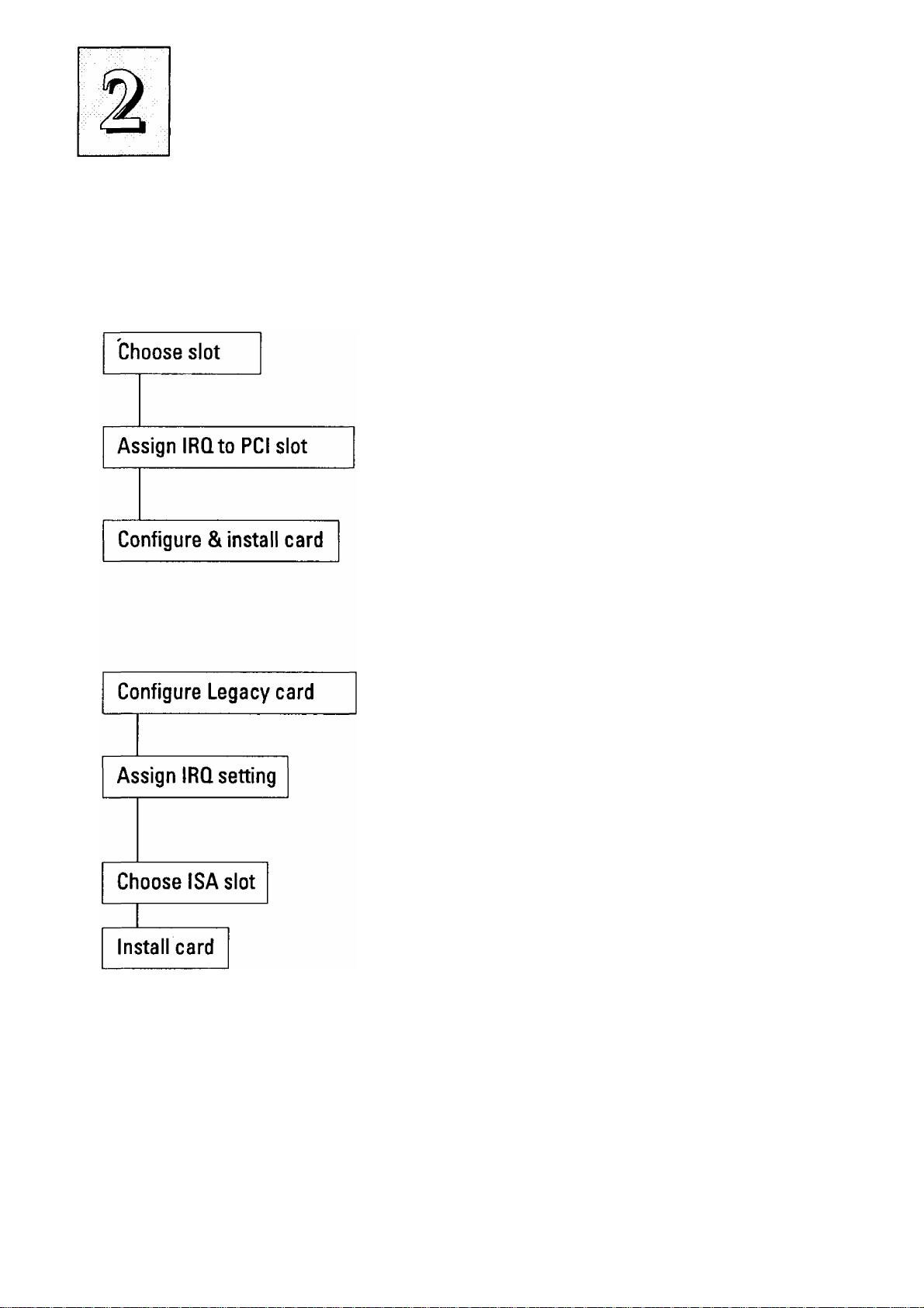
Installing Expansion Cards That Use An IRQ
Example PCI installation procedure:
1. Choose a slot to usee.g. PCI Slot 1 - fixed INT A#
2. Make sure Slot 1 is setto the "Auto"
setting
3. Configure the card you will install in
PCI Slot 1 to use INT A and install it
Example ISA installation procedure:
1. If it is a Legacy card, select the ISA
IRQ it will use. If PNP card, skip this.
e.g. IRQ 5
2. If it is a Legacy card, set IRQ 5 as used
by ISA in PCI and PNP Setup, or use
ICU. If PNP card, skip this.
3. Choose an ISA slot to use •
e.g. ISA Slot1
4. Install the card in ISA Slot 1. For a PNP
ISA card, use an ICU to record the new
configuration.
2-4
Page 25

upgrade Guide
Upgrading System Memory
This section explains how to install system memory. There are
instructions on how to configure and install memory and an expla
nation of the technical specifications required.
System DRAM is the main source of data for the CPU. Data re
mains stored in DRAM as long as the system is turned on, and is lost
when you turn it off. The Level 2 cache memory is Static RAM
(SRAM), which is faster than DRAM memory. When the CPU looks
for data, it first searches the cache. If the information is not there, the
search continues in the DRAM. With this design, the CPU looks in
the fastest source of data first, which lets it operate as fast as possible.
The DRAM subsystem uses memory chips permanently mounted
on small circuit boards to form "SIMMs" (Single In-line Memory
Modules). The memory chips have a speed rating that is measured
in nanoseconds (ns). This mainboard requires either Fast Page Mode
(FPM) DRAM or Extended Data Output (EDO) DRAM with a speed
of at least 60 or 70ns depending on the bus clock/CPU external clock
speed setting.
This mainboard can use 72-pin SIMMs in four sizes from 4MB up
to 32MB (megabytes). Depending on the combination of modules you
use, you can install between 8MB and 128MB. The 32-bit modules
used for this board come with memory chips on either one or both
sides of the module.
2-5
Page 26

P/I-AP55T User's Manual
Configuring System Memory
If you want to add system memory, you must use the configura
tion options and specifications shown in this section.
Memory Combinations
You can configure the system memory in a variety of ways, us
ing different combinations of SIMM modules. Using the 4 SIMM
sockets there are many configuration options.
The following chart shows the supported combinations.
The only restrictions are:
• You must use 2 sockets at a time, in sequence, i.e. SIMM 1
and SIMM 2, or all four sockets at once.
• Each pair of modules must be the same size and speed and
can be either single or double-sided.
• Memory Specifications:
Module Size:
Single-sided SIMMs: 4MB, 16MB
Double-sided SIMMs: 8MB, 32MB
DRAM Type: Fast Page Mode or Extended Data Output
DRAM Speed: 70ns or faster for 75MHz, 90MHz and 120MHz
Pentiiims (50 or 60MHz external clock); 60ns for lOOMHz and
133MHz Pentiums (66MHz external clock).
2-6
RAS access time [Trac]: 60ns - 70ns
CAS access time [Tcac]: 10ns - 25ns
Parity: Either parity or non-parity
Page 27

upgrade Guide
Memory Module Combinations
BankO
Sockets 1&2
4MB X 2 None
8MBx2
16MB X 2 None
32MB X 2 None
* Note: The configurations above can use Bank 1 and leave Bank 0 empty instead
4MBx2 4MBx2
4MBx2 8MB X 2
4MBx2 16MB X 2
4MBx2 32MB X 2
8MB X 2
8MB X 2 8MB X 2
8MB X 2
8MB X 2 32MB X 2
Banki
Sockets3&4
Mone 16MB*
4MBx2 24MB
16MB x 2 48MB
Total Memory Using Sockets
1 through 4
8MB*
32MB*
64MB*
16MB
24MB
40MB
72MB
32MB
80MB
16MBx2 4MBx2
16MBx2 8MB X 2
16MB X 2
16MB X 2
32MB X 2
32MB X 2
32MB X 2
32MB X 2
IMPORTANT; Do not use SIMM modules with more than 24 chips per
module with this mainboard. Modules with more than 24 chips exceed the
design specifications of the memory subsystem and will cause unreliable
operation. DO NOT use 32 or 36-chip modules with this mainboard.
16MB X 2
32MB X 2
4MBx2
8MB X 2 80MB
16MB X 2
32MB X 2
40MB
48MB
64MB
96MB
72MB
96MB
128MB
2-7
Page 28

P/I-AP55T User’s Manual
Installing SIMMs
To install SIMMs follow these instructions:
1. The modules will only insert in a socket in one orientation. An
- orientation cut-out will prevent you from inserting them the
wrong way. See the figures at right.
2. Press the module edge connector into the socket at a moder
ate angle to the board. See the figures below.
3. Press the module forward onto the socket's vertical posts, so
that the alignment pins at the top of each post go into the cir
cular holes at each end of the module.
4. The module should click into place, as the retaining clips at
each end of the socket snap behind the module to secure it.
5. Repeat this procedure for each module you install.
Installing a Memory Module
Insert the SIMM
into the socket at
an angle.
Press it forward
onto the position
ing pins.
2-8
The retaining clips
should fit over the
edge and hold the
SIMM in place.
Page 29

Cut-out
SIMMs have a cut-out at one end that matches an
extension on one of the vertical posts of each socket.
Put orientation cut-out at this end.
SIMM# 4 3 2 1
V£T
E
Install modules starting with the SIMM1 socket on the righthand side. Modules may have chips on one or both sides.
2-9
Page 30

P/I-AP55T User's Manual
Upgrading Video DRAM Memory
The mainboard comes with 1MB of video display DRAM
mounted on it. In addition, there are two expansion sockets that al
low you to expand the video display memory to 2MB.
To expand the video display memory, you must install two 512KB
DRAM chips in the expansion sockets. To install the chips, observe
static discharge precautions and do as follows:
1. Open your system case and find the video display memory ex
pansion sockets, located near the monitor port.
2. Identify the Pin 1 comer of the socket. The Pin 1 comer is the
upper left-hand comer from the point of view of the mainboard diagram on page 1-7 in Chapter 1.
3. Identify the Pin 1 comer of the DRAM chip. It should have a
small dot indentation on the top of the chip at that comer.
4. Align the chip to the socket so that the Pin 1 comers match and
press the chip into the socket.
5. Repeat steps 1 through 3 for the second socket and chip.
6. When you are done, reassemble your system and turn it on.
Information about the video display appears first. Check to see
that the memory total displayed is 2MB. If this is correct, the
chips are correctly installed and the system is using the new
display memory.
Please see Chapter 4 for information on the required specifica
tions for the video display memory expansion DRAM chips.
2-10
Page 31

upgrade Guide
Installing IDE Hard Disks
This section explains how to install IDE hard disk drives or other
devices. You can connect up to four ГОЕ devices to the onboard con
nectors. This section explains the information specific to this
mainboard, not the basic procedure for how to install a hard disk in
your system. Your system manual should have instructions specific
to installing devices in your case.
Note: If you already have a SCSI hard disk installed and you in
stall an ГОЕ drive, the ГОЕ drive must be the "Primary Master" drive.
Installing a Primary IDE Hard Disk
To install a first ГОЕ hard disk do the following:
1. Follow the instructions in your computer system manual for
installing a hard drive in an empty drive bay and connecting
a power cable.
2. Cormect one end of the IDE ribbon cable to the drive and the
other to the Primary ГОЕ cormector on the mainboard with the
colored edge of the cable at the Pin 1 side of both the drive and
mainboard connectors.
3. Connect the drive LED connector to the ГОЕ activity LED con
nector on the mainboard.
4. Reassemble and turn on the system and run the BIOS Setup
Utility.
5. Use ГОЕ FTOD Auto Detection in the BIOS Setup utility to de
tect and enter the drive peirameters for "Primary Master".
Note: If the device you install is not a hard disk drive, you should
leave the Standard CMOS Setup entry for "Primary Master" set to
"None".
2-11
Page 32

P/I-AP55T User’s Manual
Installing Additional IDE Devices
If you have space in your system case, you can install another ГОЕ
hard disk or other IDE device using the procedure on the previous
page. Install the drive in an empty drive bay and cormect the drive
to the unused middle connector of the ГОЕ ribbon cable. Note that a
second IDE device on a channel must be set to function as a "slave"
device, because the first ГОЕ device functions as the "master" device.
The device manual should tell you how to do this. Many ГОЕ devices
use jumpers to select this setting.
Once you have installed the device, you may need to use the BIOS
Setup Utility again to configure and record the presence of the sec
ond device in the Standard CMOS Setup. The Primary channel is
shown as "Primary Master" and "Primary Slave", the Secondary
channel as "Secondary Master" and "Secondary Slave". If the device
you installed is not a hard disk drive, you should leave the Standard
CMOS Setup entry for its position set to "None".
See Chapter 3 for an explanation of how to use the hard disk auto
detection feature to automatically detect the parameters of IDE hard
disks and other devices and enter them in the Standard CMOS Setup.
2-12
Page 33

upgrade Guide
Updating the Flash BIOS
This mainboard has two BIOS ROM chip options. It can use ei
ther of two programmable 'flash' EPROM chips, 5-volt or 12-volt,
either of which you can update when BIOS upgrades are available.
Jumper JP9 enables programming for the BIOS ROM chip. There
are two settings. The default setting, which shorts pins 1&2, is for
Write-Protect/Normal Read. The other setting, which shorts pms
2&3, is for Enable Programming.
When you finish programming, always set JP9 back to the default
Write-Protect/Normal Read setting.
The following example illustrates this procedure.
BIOS Update Procedure
1.
Set JP9 to the Programming
Enabled setting.
Refer to Chapter 3 for instruc
2.
tions on using the Flash Memory
Writer Utility to install a new
BIOS file in the flash chip.
When you have successfully
3.
installed the new BIOS, set JP9
back to the Write Protect/Normal
setting to disable programming.'
2-13
Page 34

P/I-AP55T User's Manual
Installing a Pentium Upgrade
If yoiir mainboard has a "Socket 7" ZBF socket and Header 7 VRM
(Voltage Regulator Module) socket, you can install a Pentium upgr,ade processor ruiming at either 150MHz or 167MHz. The upgrade
package will consist of the Pentium CPU and the required VRM.
To install an upgrade processor, follow the instructions that come
with the upgrade. Remember to take careful precautions against static
electric discharge. The basic procedure will be as follows:
1. Turn off and discormect everything and open your system
2. Remove the existing CPU from the ZIP socket.
3. Follow the instructions that come with your upgrade kit for
installing the upgrade components.
4. Reassemble the system and turn it on to make sure everything
is working correctly.
As with any upgrade, if you are not comfortable doing the work
yourself, you may want to have your system vendor, dealer or a ser
vice technician do the work for you. This is a particularly good idea
where expensive and easily damaged components are concerned.
2-14
Page 35

Software Guide
This chapter explains the Setup Utility for the Award BIOS, the
SCSI BIOS and drivers, and the system BIOS flash memory update
utility.
Award BIOS Setup
All computer mainboards of this type have a 'Setup' utility pro
gram stored in the BIOS ROM that is used to create a record of the
system configuration and settings. If you received your mainboard
installed as part of a system, the proper entries have probably already
been made. If so, you might want to call up the Setup Utility, as de
scribed later, to take a look at them, and perhaps record them for fu
ture reference, particularly the hard disk specifications.
If you are installing the board or reconfiguring your system,
you'll need to enter new setup information. This section explains how
to use the program and make the appropriate entries.
The Setup Utility is stored in the BIOS ROM. When you turn the
computer on, a screen message appears to give you an opportunity
to call up the Setup Utility. It displays during the POST (Power On
Self Test). If you don't have a chance to respond, reset the system by
simultaneously typing the <Ctrl>, <Alt> and <Delete> keys, or by
pushing the 'Reset' button on the system cabinet You can also restart
by turning the system OFF then ON.
This message will then reappear:
TO ENTER SETUP BEFORE BOOT PRESS CTRL - ALT - ESC OR DEL KEY
3-1
Page 36

P/I-AP55T User's Manual
After you press the <Del> key the main program screen will ap
pear, displaying the following choices.
Main Program Screen
ROM PCI/ISA BIOS{PI-5XTP4:
CMOS SETUP tJTILITY
AWARD SOFTWARE,INC.
STANDARD CMOS SETUP
BIOS FEATURES SETOP
CHIPSET FEATURES SETUP
POWER HANAGQfENT SETUP
PCI AND PNP SETUP
LOAD BIOS DEFAULTS
LOAD SETUP DEFAULTS
ESC : Quit
FIO Save i Exit Setup
Time, Date, Hard Dis)c Type. .
SUPERVISOR PASSWORD
USER PASSWORD
IDE HDD AUTO DETECTION
SAVE & EXIT SETUP
EXIT WITHOUT SAVING
; Select Item
(SHIFT)F2 : Change Color
This screen provides access to the utility's various functions.
Note: The 'BIOS Defaults' are minimized settings for trou
bleshooting. Use the 'Setup Defaults' to load optimized defaults for
regular use. If you choose defaults at this level, it modifies all appli
cable settings.
A section at the bottom of the screen explains the controls for this
screen. Use the arrow keys to move between items, <Shift>-i-<F2> to
change the color scheme of the display and <Esc> to exit the utility.
If you want to save changes, press the <F10> key to save the changes
you made and exit the utility. Another section at the bottom of the
screen displays a brief explanation of the item highlighted in the list.
3-2
Page 37

Software Guide
Standard CMOS Setup
"STANDARD CMOS SETUP" records some basic system hard
ware information and sets the system clock and error handling. If
your mainboard is already installed in a working system you will not
need to do this. If the configuration record which gets stored in the
CMOS memory on the board is lost or corrupted, or if you change
your system hardware configuration, you will need to recreate the
record. The configuration record can be lost or corrupted if the on
board battery that maintains it weakens or fails.
Standard CMOS Setup Screen
ROM PCI/ISA BIOS(PI-5XTP4)
STANDARD CMOS SETUP
AWARD SOFTWARE, INC.
Dace (ntn:dd:yy) : Tu«, Feb 10 1995
Time (hh:nm:ss) ; 10: 00: 00
HARD DISKS TYPE SIZE CYLS HEADS PRECOMP LANDZ SECTOR
Primary Master
Primary Slave
Secondary Master None 0
Secondary Slave
Drive A 1.2M ,
Drive B : 1.44M,
Video BGA/VGA
Halt On All Errors
BSC
Quit
FI
Help
User 547
None 0
None 0
5.25 in.
3.5 in.
n^i-
(SHIFT»P2
530 32 0 1059
0 0
0 0 0
0 0
Extended
Select Item
Change Color
0 0
0 0
Base
Memory:
Memory:
Memory;
Other
Memory:
Total
PU/PD/-*-/- : Modify
MODE
LEA
63
0 •
0
0
0
640K
7168K
384K
8192K
3-3
Page 38

P/I-AP55T User's Manual
"STANDARD CMOS SETUP" displays a screen with a list of en
tries. Follow the on-screen instructions to move around the screen.
Instructions at the bottom of the screen list the controls for this screen.
Use the arrow keys to move between fields, and the <Page Up>
('PU')/ <Page Down> (TD') or plus and minus keys to change the op
tion shown in the selected field. Pressing <Shift>+<F2> changes the
color scheme of the display, and <Esc> exits this level and returns to
the main screen.
Modifiable fields appear in a different color. If you need infor
mation about what changes to make, press the <F1> key. The help
menu will then give you information on the item highlighted. The
display of available memory at the lower right-hand side of the screen
functions automatically.
Date & Time
The first two lines on the screen are the date and time settings for
the system clock.
Hard Drive Type
You must enter the specifications of all non-SCSI hard disk drives
installed in your system. MFM, ESDI and ГОЕ hard disks all need to
have their specifications recorded here. The onboard PCI ГОЕ connec
tors provide two channels. Primary and Secondary for connecting up
to four ГОЕ hard disks or other IDE devices, two to each channel.
Only hard disks need to be entered here.
3-4
Page 39

Software Guide
If you have one or more SCSI hard disks installed in your system,
you do not need to enter their specifications here. SCSI drives oper
ate using device drivers and are not supported directly by any cur
rent PC BIOS. If your mainboard has the SCSI controller card option,
and you will use it, see the SCSI instructions that follow later in this
section. If you have some other SCSI controller, follow the instruc
tions that came with it on how to install any required SCSI driver.
The are four hard disks listed "Primary Master", "Primary Slave"
"Secondary Master" and "Secondary Slave". For each ГОЕ channel,
the first device is the 'master' and the second device the 'slave'.
To enter the specifications for an MFM or ESDI hard disk drive,
you must first select a 'type'. You can select the "User" option and
enter the specifications yourself manually or there are 45 predefined
drive specifications which you can look through to see if the specifi
cations for your drive are assigned a type number. Do this by using
the <Page Up> or <Page Down> key to change the option Usted af
ter the drive letter.
For an IDE hard drive, you should use the auto-detection utility
described later to enter the drive specifications automatically. If you
want to do this, leave the drive set to "None". You can enter the speci
fications yourself manually by using the User option if you want to.
There are six categories of information you must enter: "Cyls"
(number of cylinders), "Heads" (number of read/write heads),
"Precomp" (write precompensation), "LandZ" (landing zone), "Sec
tor" (number of sectors) and "Mode". The "Size" entry is automati
cally determined by the other specifications. Your hard disk vendor's
or system manufacturer's docximentation should provide you widv
the drive specifications. If you have an IDE drive, vmless your drive
is already formatted with specifications different from those detected
by the auto-detection utility, the easiest thing to do is use the auto
detection feature to enter the drive specifications.
3-5
Page 40

P/I-AP55T User's Manual
Mode Setting For Hard Disk Drives Larger Than 528MB
The last of the specification entries. Mode, requires additional
explanation. The Mode settings are for ГОЕ hard disks only. You can
ignore this item for MFM and ESDI drives. There are three entries you
can select from in the Mode field, "Normal", "Large" and "LBA".
Set Mode to the Normal setting for ГОЕ hard disk drives smaller
than 528MB. Use the LBA setting for drives over 528MB that use Logi
cal Block Addressing mode to allow larger ГОЕ hard disks. The Large
setting is for drives over 528MB that do not use the LBA mode. This
type of drive can only be used with MS-DOS and is uncommon. The
majority of IDE drives over 528MB use the LBA mode.
Note: Entering incorrect drive specifications will result in a hard
disk drive functioning improperly or not at all.
Floppy Disk Drives
The next two lines record the types of floppy disk drive present.
The options for drives A and В are:
360KB, 5.25 in.
1.2MB, 5.25 in.
720KB, 3.5 in.
1.44MB, 3.5 in.
2.88MB, 3.5 in.
None
Highlight the listing after each drive name and select the appro
priate entry.
3-6
Page 41

Software Guide
Video Display Types
''Video" refers to the type of video display card your system has.
The options are:
EGA/VGA
Mono (for Hercules or MDA)
CGA 40
CGA 80
You should select the setting that matches your video display
card. If you have a VGA or any higher resolution card, choose the
EGA/VGA setting.
Error Handling
The last line "Halt On" controls whether the system stops in case
of an error. The options are;
All Errors
No Errors
All, But Keyboard
All, But Diskette
All, But Disk/Key
For most purposes, we suggest that you leave the setting on the
default, "All Errors", unless you know why you want to use a dif
ferent setting.
When you have made your selections, exit to the main program
screen by pressing the <Esc> key.
3-7
Page 42

P/I-AP55T User’s Manual
BIOS Features Setup
"BIOS FEATURES SETUP" is a list of system configuration op
tions. Some entries are defaults required by the mainboard's design.
Others will improve your system's performance if enabled, or let you
set up some system features according to your preference.
BIOS Features Setup Screen
ROM PCI/ISA BIOS(PI-5XTP4)
BIOS FEATURES SETUP
AWARD SOFTWARE INC.
Virus Warning
CPU Internal Cache
External Cache
Quick Power On Self Test
Boot Se<№ence
Swap Floppy Drive
Boot Up Floppy seek
Boot Up NuxnLock Status
Boot Up System Speed
IDE HDD Block Mode
IDE 32-bit Transfer Mode
TVpcnmtic Rate Setting
IVpcratic Rate (piars/Sec)
TVpematic Delay (Msec)
Security Option
IDE Second Channel Control
:Disabled
Enabled
Enabled
Ened>led
C,A
Disabled
Disabled
On
High
Enabled
Enabled
Disabled
6
250
System
Enabled
Video
C8000CCOOODOOOOD4000D8000DCOOOEOOOO'
E4000E8000'
ECOOO-
ESC
FI
F5
F6
F7
BIOS
CBFFF
CFFFF
D3FFF
D7FFF
DBFFF
DFFFF
E3FFF
E7FFF
EBFFF
•EFFFF
Quit
Help PU/PD/+/Old Values (SHIFT)F2
Load BIOS Defaults
Load Setup Defaults
Shadow
Shadow
Shadow
Shadow
Shadow
Shadow
Shadow
Shadow
Shadow
Shadow
Shadow
EneUsled
Disabled
Disabled
Disedoled
Di saddled
Disabled
Disabled
DiseUoled
Disabled
Dis2±)led
Disabled
T4—
: Select Item
Modify
Color
A section at the lower right of the screen explains how to navi
gate and make changes. The controls are the same as for the Standard
CMOS Setup.
If you need information about what changes to make, highlight
an entry and press the <F1> key. A pop-up help menu will display
information about the highlighted item. Press the <F5> key to recall
the last set of values saved for this page. Pressing the <F6> key loads
the BIOS default values for this page and <F7> loads the Setup de
fault values.
The following explains the options for each entry and indicates
the default settings (Setup Defaults) for this screen.
3-8
Page 43

Software Guide
Virus Protection
The "Virus Warning" default setting is "Disabled". This feature
protects the boot sector and partition table of your hard disk. Any
attempt to write to them will halt the system and cause a warning
message to appear. If this happens, you can either allow the opera
tion to continue or stop it and use an anti-virus utility on a virus-free
bootable floppy disk to reboot and investigate your system.
Cache Control
The "CPU Internal Cache" and "External Cache" default settings
are "Enabled". These settings enable CPU's 'Level 1' built-in cache
and the 'Level 2' secondary cache. The BIOS Default settings will dis
able the L2 cache. Leave both enabled unless you are troubleshoot
ing a problem.
Boot Up Features
The "Quick Power On Self Test" default setting is "Enabled".
This speeds up the Power On Self Test (POST) by skipping some items
that are normally checked during the full POST. If your system is
functioning normally, you can use this feature to speed the boot up
process.
The "Boot Sequence" default setting is "C:, A:"; the other option
is "A:, C:". The setting determines where the computer looks first for
an operating system, the hard disk or the floppy drive.
The "Swap Floppy Drive" default setting is "Disabled". When
enabled, the BIOS will swap floppy drive assignments so that Drive
A will function as Drive B: and Drive B: as Drive A: under DOS.
The "Boot Up Floppy Seek" default setting is "Disabled". When
enabled, the BIOS will check if there is a 360KB floppy disk drive
installed. Don't change this unless there is a 360KB drive installed.
3-9
Page 44

P/I-AP55T User's Manual
The default "Boot Up NumLock Status" setting is "On". When
the computer boots, the numbers on the numeric keypad of an IBMcompatible extended keyboard will be active. If you turn this off the
keypad cursor controls will be active.
' "Boot Up System Speed" sets the CPU speed at boot up. The de
fault setting is "High".
IDE Modes
The "IDE HDD Block Mode" default setting is "Enabled". This
feature enhances hard disk performance by making multi-sector
transfers instead of one sector per transfer. Most IDE drives, except
very early designs, can use this feature.
The "IDE 32-bit Transfer Mode" default setting is "Enabled".
This feature allows 32-bit data transfer between the system and the
ГОЕ hard disks if the hard disk controller supports 32-bit transfer. The
onboard PCI ГОЕ controller supports 32-bit transfer, so if you use it,
you can enable this feature to improve performance.
Keyboard Interface
The "Typematic Rate Setting" default setting is "EHsabled
enabled, you can set the typematic controls that follow.
The "Typematic Rate (Char/Sec)" controls the speed at which the
system registers repeated keystrokes. The choices range from 6 to 30
characters per second (default is 6).
The "Typematic Delay (Msec)" controls the time between the
If
display of the first and second characters. There are four delay rate
choices: 250ms, 500ms, 750ms and 1000ms (default is 250ms).
3-10
Page 45

Software Guide
Password Control
The "Security Option" controls the Password Setting in the main
screen. The default setting is "System", uses the User Password fea
ture every time you boot up. The other setting is "Setup". This will
allow the system to boot, and use the Supervisor Password only to
protect the Setup Utility settings from being tampered with. You cre
ate a password by using the Supervisor or User Password command
from the main screen as explained later in this section.
IDE Second Channel Control
The "IDE Second Channel Control" default setting is "Enabled".
If you do not want to use the second onboard Enhanced ГОЕ chan
nel, disable this. When the second channel is enabled, it uses IRQ 15,
whether or not you connect anything to the onboard connector.
Shadow Controls
The default setting for the "Video BIOS Shadow" is "Enabled".
This copies the video display card BIOS into system DRAM to im
prove performance.
The next ten lines, "C8000-CBFFF Shadow" to "ECOOO-EFFFF
Shadow" are for shadowing other expansion card ROMs. The default
setting for these areas is "Disabled". If you have other expansion
cards with ROMs on them, you will need to know which addresses
the ROMs use to shadow them specifically. When you shadow a ROM
it reduces the memory available between 640KB and 1024KB by the
amount used for shadowing.
After you have made your selections in BIOS Features Setup,
press the <Esc> key to go back to the main screen. The next item is
Chipset Features Setup.
3-11
Page 46

P/I-AP55T User’s Manual
Chipset Features Setup
This screen controls the settings for the mainboard's chip set. The
controls for this screen are the same as for the previous screen.
Chipset Features Screen
ROM PCI/ISA BIOS(PI-5XTP4)
CHIPSET FEATURES SETUP
AMARD SOFTWARE INC.
Auto Configuration Enabled
DRAM Read Timing EDO/STD X222/X333
DRAM Write Timing
RAS To CAS Delay
DRAM Leadoff Timing
PCI Concurrency Enabled
PCI Streaming Enabled
CPU to PCI Burst
16-bit I/O Recovry Time
8-bit I/O Recovry Time
Video BIOS Cacheable
Memory Hole At 15H-16M Disabled
x222
3T
7T
Enabled
3 BUSCLK
3 BUSCLK
Disêübled
Onboard IDE Timing
Onboard FDC Controller
Onboard FDC Swap A & B No Swap
Onboard Serial Port 1
Onboard Serial Port 2
Onboard Parallel Port
Parallel Port Mode
SMC ECP DMA Select
UART2 Use Infrared
Fastest
Enabled
C0M1,3F8H
COM2,2F8H
378H/IRQ7
Normal
Disabled
: Disabled
ESC : Quit Ti-M- : Select Item I
FI : Help PÜ/PD/+/
F5 : Old Values (SHIFT)F2 : Color 1
F6 : Load BIOS Defaults
F7 ; Load Setup Defaults
: Modify 1
The first ten lines after Auto Configuration are optimal settings
for this mainboard that are defined by the Auto Configuration fea
ture, which configures the settings based on the CPU clock speed. You
should not change them unless you know what you are doing.
You can enable the Memory Hole feature if you need it for an
expansion card you are installing. Refer to the card documentation
for instructions regarding this feature.
3-12
Page 47

Software Guide
Controller Settings
The default setting for "Onboard IDE Timing" is "Fastest",
which provides optimum performance for Enhanced ГОЕ Modes 3
and 4. К the hard disk drive(s) installed in your system can not use
the fcistest timing, you should change the setting to "Fast". If you have
any hard disk installed that does not support Mode 3 and 4 timing,
you should set this line to the "Standard" setting.
Note: This line also has a "Disable" setting. If you disable this line,
it disables the onboard ГОЕ controller. Make sure you do this if you
want to use an ГОЕ controller other than the one on the mainboard.
The default setting for the "Onboard FDC Controller" is "En
abled". This setting allows you to connect your floppy disk drives to
the onboard "Floppy" connector instead of a separate controller card.
Choose the "Disabled" setting if you want to use a separate control
ler card.
The default setting for the "Onboard FDC Swap A: B:" is "No
Swap". If you want to reverse the drive letter assignments of your
floppy disk drives you can set this to "Swap AB" and the swap will
be controlled in hardware. This works separately from the BIOS Fea
tures floppy disk swap feature. It is functionally the same as physi
cally changing the floppy disk drive cable connector positions.
3-13
Page 48

P/I-AP55T User’s Manual
Serial Ports
The "Onboard Serial Port 1" and "Onboard Serial Port 2" lines
control the assignments for the mainboard's two onboard serial con
nectors. They can be assigned as follows:
COMl, 3F8H (Onboard Serial Port 1 default)
COM2,2F8H (Onboard Serial Port 2 default)
COM3, 3E8H
COM4, 2E8H
Disabled turns off the onboard ports
Parallel Port
The options for "Onboard Parallel Port" are:
3BCH/IRQ7
378H/IRQ7
278H/IRQ5
EHsabled
This line controls the onboard parallel port and connector, setting
the port address and IRQ assignment or disabling the port. It should
be unnecessary to change the default setting.
Parallel Port Mode
The options for "Parallel Port Mode" are;
Normal
EPP
ECP
Default setting
Default setting
default DMA 3
ECP&EPP
If you want to use one of the parallel port enhancements listed,
set this line for the enhanced mode your peripheral supports. "ECP"
automatically sets the "ECP DMA Select" line to "3", where it is oth
erwise set to "Disabled", and carmot be set independently.
3-14
Page 49

Software Guide
ECP DMA Select
If you select the ECP parallel port feature on the previous line,
the BIOS will auto-select DMA channel 3 for the "ECP DMA Select"
line. This line does not appear unless the ECP feature is selected.
UART2 Use Infrared *
The default setting for the "UART2 Use Infrared " is "Disabled".
The default setting leaves the second serial port UART set to support
the Serial Port 2 connector. The "Enabled" setting activates the
onboard infrared IrDA feature and sets the second serial UART to
support the infrared module connector on the mainboard instead.
Choose this if you want to connect an infrared control module to the
mainboard. The onboard COM2 serial port will no longer work if you
enable the infrared feature.
When you are done with this section, press the <Esc> key to go
back to the main screen.
3-15
Page 50

P/I-AP55T User's Manual
Power Management Setup
Power Management Setup controls the mainboard's "green" fea
tures. The features shut down the video display and hard disk to save
energy.
THb Power Management Setup Screen
ROM PCI/ISA BIOS (PI-5XTP4)
POWER MANAGEMENT SETUP
AWARD SOFTWARE INC.
Power Management
Video Off Option
Video Off Method
Suspend Switch
Doze Speed (div by)
Stdby Speed(div by)
** PM Timers
HDD Power Down
Doze Mode
Standby Mode
Suspend Mode
** PM Events
IRQ3
IRQ4
IRQ8
IRQ12
(Wake-Up)
(Wake-Up)
(Wake-Up)
(Wake-Up)
User Define
Susp,Stdby->Off
V/H SYNC+Blank
Enable
8
32
Disable
Disable
Disable
Disable
Disable
Enable
Disable
Enable
IRQ3
IRQ4
IRQ5
IRQ6
IRQ7
IRQ8
IRQ9
IRQIO
IRQll
IRQ12
IRQ13
IRQ14
IRQ15
(COM 2)
(COM 1}
(LPT 2)
(Floppy Disk)
(LPT 1)
(RTC Alarm)
(IRQ2 Redir)
(Reserved)
(Reserved)
(PS/2 Mouse)
(Coprocessor)
(Hard Disk)
(Reserved)
ESC : Quit :Select Item
FI : Help PU/PD/ + /- : Modify
F5 : Old Values (SHIFT)F2 : Color
F6 ; Load BIOS Defaults
F7 : Load Setup Defaults
Disable
Enable
Enable
Enable
Enable
Disable
EnaJale
Enable
Enable
Enable
Enable
Enable
Enable
Power Management
"Power Management" is the master control for the power sav
ing modes. Display Turn off and HDD Power Down that together
form the hardware power conservation scheme. There are four set
tings:
Max Saving
Sets the power conservation options to maxi
mize power saving by putting the system into
power saving mode after a brief period of sys
tem inactivity.
3-16
Page 51

Software Guide
Min Saving
Disable
User Defined
Max Saving
The "Max Saving" defaults are "1 Min" and "1 Min".
Min Saving
The "Min Saving" defaults are "20Min" and "1 Hour".
Video Off
Another set of power saving assignments
which activate each after a moderate period
of system inactivity.
Turns off all power saving
Allows you to set power saving options ac
cording to your requirements. (Default)
The "Video Off Option" default is "Susp,Stby-> Off". This line
defines when the video off features activate. The next line sets how.
The "Video Off Method" default is "V/H SYNC+Blank". The
other options are "DPMS"and "Blardc Only". When power manage
ment blanks the monitor screen, the default setting blanks the screen
and turns off vertical and horizontal scanning. The DPMS (Display
Power Management System) setting allows the BIOS to control the
video display card if it has the DPMS feature. If you don't have a
"Green" monitor, use the Blank Only option.
Note: "Screen Saver" software does not work with this feature.
Screen savers are to prevent burning in a static image on the CRT
while the monitor is on. A screen saver cannot display while the
monitor is shut down to save both electricity and the screen.
3-17
Page 52

P/I-AP55T User’s Manual
Suspend Switch
The "Suspend Switch" default is "Enable". This enables the SMI
connector on the mainboard. The SMI connector connects to the lead
from a Suspend switch mounted on the system case.
Doze & Standby Speeds
The next two lines set the speed the CPU will operate at during
each mode. The number indicates what the normal CPU speed is di
vided by.
PM Timers
The next lines control the time-out settings for the Power Man
agement scheme. The features are "HDD Power Down", which puts
the hard disk into its lowest power consumption mode, and the Doze,
Standby and Suspend system inactivation modes.
The system automatically recovers from any power saving mode
when there is system activity, as, for example, when you type any key,
or when there is an IRQ wake-up event such as moving the mouse
or a modem ring.
"HDD Power Down" shuts down any ГОЕ hard disk drives in
the system if they are not accessed for the specified period. The time
settings range from "1 Min" to "20 Min", or "Disable".
HDD Power Down does not affect SCSI hard disks.
The "Doze Mode", "Standby Mode" and "Suspend Mode" lines
set the period of time after which each of these modes activate. At
Tviax Saving' they activate sequentially after one minute each, at 'Min
Saving' after one hour.
3-18
Page 53

Software Guide
PM Events
If there is activity on any of the IRQs listed in the left-hand group
while the system is suspended, the system will wake up if that IRQ
is Enabled. You can enable power management for IRQs 3-15 indi
vidually in the list at the right of the screen. The power management
scheme will work on the enabled IRQs.
Note: Normally, a Microsoft serial mouse or compatible will use
either COMl (IRQ4) or COM2 (IRQ3) and a PS/2-type mouse will
use IRQ12. If you know which IRQ your mouse is using, you can
make sure the Wake-up Event for that IRQ is turned on here and the
system will wake up when you move the mouse or click a button.
IRQ3 to IRQ15 Individual Settings
You can set IRQs 3-15 individually. Activity on any enabled IRQ
will wake up the system.
When you are done here, press the <Esc> key to go back to the
main screen.
3-19
Page 54

P/I-AP55T User's Manual
PCI and PNP Configuration Setup
This screen configures the PCI Bus slots. All the slots use INTA#.
If you install a card , you should set the card to INTA#.
PCI And PNP Configuration Setup Screen
ROM PCI/ISA BIOS(PI-5XTP4:
PCI AND PNP SETUP
AWARD SOFTWARE INC.
SLOT 1 (Top) IRQ ; Auto
SLOT 2 IRQ r Auto
SLOT 3 (Bottom) IRQ; Auto
PCI Latency Timer : 80 PCI Clock
IRQ 3 Used By
IRQ 4
IRQ
IRQ 'j
IRQ 10
IRQ 11
IRQ 15
Used By
5 Used By
Used By
Used By
Used By
Used By
ISA
No/ICU
ISA No/ICU
ISA
No/ICU
ISA
No/ICU
ISA :
; No/ICU
ISA ; No/ICU
ISA : No/ICU
DMA I Used By ISA : No/ICU
DMA 3 Used By ISA : No/ICU
DMA 5 used By ISA : No/ICU
ISA MEM Block Base : NO/TCU
ESC
Quit Ti—Select Item
FI
Help PU/PD/+/- : Modify
F5
Old Values (SHIFT)F2 ; Color
Load BIOS Defaults
F6
F7
Load Setup Defaults
The first four lines on the screen set how PCI slot IRQ use is de
termined. The default setting for each line is ''Auto", which will use
auto-routing to determine IRQ use. Use the options "14" or "14&15"
if you install an Enhanced IDE controller card. A card with one chan
nel should use the "14" setting and a two-channel card should use
the "14&15" setting. Please note that if you use one or both of these
IRQs here, they will not be available to the onboard PCI IDE control
ler, which uses IRQ 14 for Channel One and IRQ 15 for Channel Two.
You can not share these IRQs betw een two controllers.
3-20
Page 55

Software Guide
The next line is the "PCI Latency Hmer" setting. Do not change
the "80 PCI Clock" setting. This default setting enables maximum PCI
performance for this mainboard.
Plug And Play
The seven "IRQ ... Used By ISA" lines indicate whether or not
the IRQ indicated for each line is being used by a 'legacy' (non-PnP)
ISA card. The default setting "No/ICU" indicates either that the IRQ
is not in use by the ISA Bus or that an ISA Configuration Utility (ICU)
is being used to determine if an ISA card is using that IRQ. If you
instaU a legacy ISA card that needs a specific IRQ, and you are not
using an ICU, you must set the line for that IRQ to "Yes".
For example, if you install a PnP ISA card that needs to use IRQ
3, you would set the "IRQ 3 Used By ISA" line to "No/ICU". If, how
ever, you install a legacy ISA card that needs to use IRQ 3, and you
are not using an ICU, set the "IRQ 3 Used By ISA" line to "Yes".
The three "DMA ... Used By ISA" lines indicate whether or not
the DMA charmel listed is being used by a legacy ISA card. The de
fault setting "No/ICU" indicates either that the DMA channel is not
in use by the ISA Bus or that an ICU is being used to determine if an
ISA card is using that IRQ. If you install a legacy ISA card that needs
to use a specific DMA channel, and you are not using an ICU, you
must set the line for that channel to "Yes".
3-21
Page 56

P/I-AP55T User's Manual
If you have a legacy ISA card that uses any memory segment in
the C800h to DCOOh address range and you have not used an ICU to
specify the range it uses, you should set the base address and block
size by using the "ISA MEM Block BASE" line. When you select a
base address from the six options, the "ISA MEM Block SIZE" line
will appear and you can select a block size from the four options. If
you use an ICU to accomplish the same thing, leave "ISA MEM
Block BASE" on the default "No/ICU" setting. If you have more than
one legacy ISA card that needs to use this address range, you can
increase the block size as necessary.
When you're finished making settings for this screen, press the
<Esc> key to go back to the main screen.
3-22
Page 57

Software Guide
Load BIOS Defaults
"LOAD BIOS DEFAULTS" loads the troubleshooting default
values permanently recorded in the BIOS ROM. ITiese settings are
non-optimal and turn off all high performance features.
The Standcird CMOS Setup screen is not affected. To use this fea
ture, highlight it on the main screen and press <Enter>. A line will
appear asking if you want to load the BIOS default values. Press the
<Y> key and then <Enter>. The default settings will load. Press <N>
if you don't want to proceed.
Load BIOS Defaults Screen
ROM PCI/ISA BIOS(PI-b3CTP4)
STANDARD CMOS SETUP
BIOS FEATURES SETUP
CHIPSET FEATURES SETUP
POWER MANAGEMENT SETUP
PCI AND PNP SETUP
LOAD BIOS DKFAUIA
LOAD SETUP DEFAUT
ESC Quit
FIO Save & Exit Setup
Load BIOS Defaults except Standard CMOS SETUP
ikMÛl Bids M «
CMOS SETUP UTILITY
AWARD SOFTWARE, IKC
SUPERVISOR PASSWORD
USER PASSWORD
IDE HDD AUTO DETECTION
SAVE & EXIT SETUP
SAVING
T4—; Select Item
(SHIFT? F2 : Change Color
3-23
Page 58

P/I-AP55T User's Manual
Load Setup Defaults
The "LOAD SETUP DEFAULTS" option loads optimized set
tings from the BIOS ROM. Use this option to load default settings for
normal use.
The Setup Defaults default settings do not affect the Standard
CMOS Setup screen. To use the Setup Defavdts, highlight the entry
on the main screen and press <Enter>. A line will appear asking if
you want to load the Setup default values. Press the <Y> key and then
press <Enter>. The Setup Defaults will load. Press <N> if you don't
want to proceed.
Load Setup Defaults Screen
ROH PCX/ISA BIOS(PI-5XTP4>
STANDARD CMOS SETUP
BIOS FEATURES SETUP
CHIPSET FEATURES SETUP
POWER MANAGEMENT SETUP
PCI AND PNP SETUI
LOAD BIOS DEFAULl
LOAD SETUP DBFAUI
ESC : Quit
FIO : Save & Exit Setup
Load SETUP Defaults except Standard CMOS SETUP
CMOS SETUP UTILITY
AWARD SOFTWARE,INC.
SUPERVISOR PASSWORD
USER PASSWORD
IDE HDD AUTO DETECTION
SAVE & EXIT SETUP
SAVING
T4—M- r Select Item
(SHIFT)f2 : Change Color
3-24
Page 59

Software Guide
Setting Supervisor & User Passwords
The "SUPERVISOR PASSWORD" and "USER PASSWORD"
options set passwords. The Supervisor Password is for system and
Setup Utility access. The User Password is for the system only. The
mainboard ships with no passwords. To create a password, highlight
the type you want and press the <Enter> key. At the prompt, type
your password. The password is case sensitive, and can be up to 8
alphanumeric characters. Press <Enter> after you have finished typ
ing in the password. At the next prompt, confirm the new password
by re-typing it and pressing <Enter> again. When you're done, the
screen automatically reverts to the meiin screen. Remember, when you
use this feature, the "Security Option" line in BIOS FEATURES
SETUP will determine when entering the password will be required.
To disable either password, press the <Enter> key instead of en
tering a new password when the "Enter Password" dialog box ap
pears. A message confirms the password has been disabled.
Password Setting
ROM PCI/ISA BIOS(PI-5XTP4)
CMOS SETUP UTILITY
AMARO SOFTWARE,INC.
STANDARD CMOS SETUP SOTKItVISOR PASSWORD
BIOS FEATURES SETUP USER PASSWORD
CHIPSET FEATURES SETUP
POWER MANAGQfENT SETUP
PCI AND PNP SETUP 'OUT SAVING
LOAD BIOS DEFAULTS
LOAD SETUP DEFAULTS
Batax PMSwordi *****
IDE HDD AUTO DETECTION
SAVE & EXIT SETUP
ESC ; Quit
FIO Save & Exit Setup
Ti—: Select Item
(SHIFT)F2 :
Change/Set/Disable Password
Change Color
3-25
Page 60

P/I-AP55T User’s Manual
IDE HDD Auto Detection
If your system has an IDE hard drive, you can use this utility to
detect its parameters and enter them into the Standard CMOS Setup
automatically.
This utility will detect as many as four IDE drives if your system
configuration supports that many. In sequence, a set of parameters
for each drive will appear in the box. To accept the entries displayed
press the Y key, to skip to the next drive, press the N key. If you ac
cept the values, the parameters will appear listed beside the drive
letter on the screen and the next letter, without parameters will ap
pear and the program will attempt to detect parameters for the next
drive. If you press the N key to skip rather than accept a set of pa
rameters, zeros are entered after that drive letter.
Remember, if you use another IDE controller that does not have
Enhanced IDE support for four devices, you can only install two ГОЕ
hard disk drives. Your ГОЕ controller must support Enhanced ГОЕ
features in order to use Drive E: and Drive F:. The onboard PCI ГОЕ
controller supports Enhanced ГОЕ and has two connectors that sup
port a total of four IDE devices.
When you are finished, any entries you accepted are automati
cally entered on the line for that drive in the Standard CMOS Setup.
Any entries you skipped are ignored and nothing is entered for that
drive in Standard CMOS Setup.
Note; If you are setting up a hard disk that supports LBA mode,
three lines will appear in the parameter box. Choose the line that lists
LBA for an LBA drive. Do not choose Large or Normal.
3-26
Page 61

Software Guide
IDE HDD Auto Detection Screen
ROM PCI/ISA BI0S(P1-5XTP4)
CMOS SETOP UTILITy
AHARD 50PTHARE,INC.
HARD DISKS
Primary Master:
OPTIONS SIZE CYLS. HEADS PIUSCOKP LANDZONB SECTORS MODE
KY)
307
TYPE SIZE CYLS HEADS PRECOKP LANDZ SECTOR MODE
Select Primary Master Option (M«Skip) ? N
790.
15
65535
790 57 NORMAL
Important!: This utility will only detect one set of parameters for
an ГОЕ hard drive. Some ГОЕ drives can use more than one set. This
is not a problem if the drive is new and there is nothing on it. If the
hard disk drive is already fully formatted when you install it, and dif
ferent parameters than those detected here were used, you will have
to enter them manually.
If the parameters listed don't match the ones used when the drive
was formatted, the drive won't be readable. If the auto-detected pa
rameters displayed do not match the ones that should be used for
your drive, do not accept them. Press the <N> key to reject the val
ues and enter the correct ones manually from the Standard CMOS
Setup screen.
3-27
Page 62

P/I-AP55T User's Manual
Save And Exit Setup
The next selection on the Utilities menu is "SAVE AND EXIT
SETUP". If you select this and press the <Enter> key the values en
tered during the current session will be recorded in the CMOS
memory on the mainboard. The system will check it every time you
turn your system on and compare it to what it finds as it checks the
system. This record is required for the system to operate.
Exit Without Saving
The last selection on the main screen is "EXIT WITHOUT SAV
ING". Selecting this option and pressing the <Enter> key lets you exit
the Setup Utility without recording any new values or changing old
ones. If you want to save a new configuration, do not use this option.
If you use it, any new setting information will be lost.
You can now use your system without further reference to this
utility unless you change the system hardware configuration. Re
member, if the system configuration information stored in CMOS
memory gets corrupted, you will have to reenter it.
3-28
Page 63

Software Guide
NCR SCSI BIOS & Drivers
The NCR 53C810 SCSI BIOS is recorded on the same flash
memory chip as the system BIOS. To use the onboard NCR SCSI
BIOS, the optional SC-200 SCSI controller card must be installed in
your system.
All SCSI devices you connect to your system require driver soft
ware. The NCR SCSI BIOS directly supports SCSI hard disks imder
DOS, Windows and OS/2. It also uses device drivers that are on the
DOS-format support floppy disk that comes with the SC-200 control
ler card to support hard disks and other SCSI devices tised with DOS,
Windows, Windows NT, Novell NetWare and OS/2. These drivers
provide higher performance than the direct BIOS support. To use
these device drivers you must install them on your system hard disk
drive and add them to your system configuration files. There is also
driver support for SCSI devices used with SCO Unix. A second, SCO
Unix-format, support floppy disk has the Unix drivers on it.
See the "Readme" files that come with the drivers for instructions
on what they are and how to use them. You can print out the Readme
files with any text editor.
3-29
Page 64

P/I-AP55T User’s Manual
Flash Memory Writer Utility
Your mainboard comes with a utility to upgrade the BIOS. The
BIOS is stored on a 'flash' EPROM BIOS ROM chip on the mainboard
that can be erased and reprogrammed. This is what the Flash Memory
Writer (FMW) utility does. The utility is in the "Flash" directory on
the DOS-formatted support floppy disk that comes with the
mainboard. You will find three files in the directory:
PFLASH.EXE - the Flash Memory Writer utility
README - a text file of instructions
TRSAxxxx.AWD - a BIOS file for this mainboard
(xxxx = a 4-digit version number)
Flash Memory Writer records (or "programs") a new BIOS file
onto the flash memory chip. The BIOS file on the support disk may
be newer than the BIOS on the mainboard, so you may want to up
date your BIOS right away Compare the four numbers eifter "TR5A"
in the new BIOS file name to the last four numbers of the code that
displays in the upper left-hand comer of your screen while the Power-
On Self-Test is running. If the number from the support disk file is
larger, then you should reprogram the System BIOS. If they are the
same, don't bother. To reprogram the System BIOS, you must first do
the following:
1. Set jumper JP9 to the enable programming. When you finish
updating the BIOS, set JP9 back to the default EHsable Programming/Normal Read setting. See Chapter 4 for jumper setting
information.
3-30
Page 65

Software Guide
2. Make sure the CPU is running in 'real mode'.
FMW will not run if the CPU is operating in protected or vir
tual mode. This means that you can not run it with Windows
running or with any memory manager software (including
HIMEM.SYS). You must disable any memory manager soft
ware first. The easiest way to do this is to:
a. Boot your system from a bootable floppy disk with no
config.sys or autoexec.bat files and then run Flash Memory
Writer from a backup copy of your support disk. You can make
your back-up floppy bootable when you format it, and use one
disk for both purposes.
b. If you are using MS-DOS 6.x, you can use the feature that
allows you to confirm or abort each line of the config.sys file.
You do this by pressing <F8> while the "Starting MS-DOS..."
line is on the screen.
There are other ways to accomplish the same result. The main
point is to make sure no memory managers are running. If you aren't
sure, try running FMW, If it runs, you've succeeded. If it displays a
warning message about the CPU mode, you'll have to try again.
Once you've satisfied the two requirements mentioned above,
you can run FMW. You can copy the contents of the "Flash" directory
to your hard disk drive, or you can run the utility from a backup of
the support floppy disk. Make sure the new BIOS file is in the same
directory as the FMW utility. To run FMW, switch to the "Flash" di
rectory if you're not already in it. Type 'PFLASH' at the DOS prompt
and press the <Enter> key. The following screen will appear:
3-3Ì
Page 66

P/I-AP55T User’s Manual
The Flash Memory Writer Utility Screen
ASUSTek PHP BIOS
FLASH MEMORY WRITER VI.0
Copyright (C) 1995, ASUSTek COMPUTER Inc
Flash Type -- SST 29EE010
Current BIOS Revision: #401X0-0109
Choose one of the following:
1. Save Current BIOS To File
2. Update BIOS Main Block From File
3. Advanced Features
Enter Choice: [1]
Press BSC To Exit
There are three command options which you invoke by typing
the number of the command and pressing the "Enter" key:
1. Save Current BIOS To File
This command reads the system BIOS already installed on the
mainboard and writes a copy of it to a file in the 'Flash' di
rectory. This leaves you with a backup of your original BIOS
in case you need to re-install it. This option is highly recom
mended.
2. Update BIOS Main Block From File
This updates the BIOS main block, but not the boot block or
ESCD block, from a BIOS file on disk. This can be a new file
or the backup file created by "Save Current BIOS To File ".
3. Advanced Features
Selecting this option brings up the Advanced Features screen.
3-32
Page 67

Software Guide
There is a line at the bottom of the screen 'Tress ESC To Exit".
If you press the Escape key the program will terminate and re
turn you to the DOS prompt.
If you type a "3" and then press the "Enter" key the Advanced
Features screen will appear.
The Advanced Features Screen
Advanced Features
Flash Type -- SST 29EE010
Current BIOS Revision: t401A0-0I09
Choose one of the following:
1. Clear PHP ESCD Parameter Block
2. Update BIOS Including Boot Block and ESCD
Enter Choice: [2J
Press Ж8С To Exit
There are two commeind options which you invoke by typing the
number of the command and pressing the "Enter" key:
1. Clear PnP ESCD Parameter Block
This command erases the Plug and Play configuration record.
2. Update BIOS Including Boot Block and ESCD.
This updates the Boot Block, the BIOS and the Plug and Play
ESCD Pcirameter Block from a new file in the FLASH directory.
Operation and controls are the same as for the main screen.
3-33
Page 68

P/I-AP55T User's Manual
Follow this procedure to update the Plug and Play system BIOS:
1. Back up your existing system BIOS by using the "Save Current
BIOS To File" command. Type "1" and press "Enter" to execute
the command. A second screen will appear.
Type the BIOS file name, e.g. TR5A0109.AWD, press "Enter"
and the program will write a file containing the current BIOS
to the directory you are nmning FMW from.
2. Install the new BIOS using the "Update BIOS Main Block From
File" command. Type a "2" and press "Enter".
When you type this command a second screen will pop up
instructing you to type in the name of the new BIOS file. Type
in the whole file name, e.g. TR5A0110.AWD and press the "En
ter" key to confirm that you want to program the BIOS. The
utility will then install the new BIOS file.
DO NOT TURN OFF THE SYSTEM IF THERE IS A PROBLEM!
If you have a problem installing the new BIOS file, try again.
If you are only updating the main block choose command "2"
"Update BIOS Main Block From File" again and try again. If
you are updating the main block, boot block and ESCD block,
you must use the Advanced Features command "2", "Update
BIOS Including Boot Block And ESCD", If you can not suc
cessfully program the new BIOS file for whatever reason, re
install your original BIOS from the backup file you created in
Step 1 above.
3-34
Page 69

Technical Summary
This section provides additional information on the technical
specifications of the mainboard. The second part explains how to set
up the optional PCI-SC200 SCSI Interface card.
Jumper Setting Summary
Base Address Selector: JP1 & JP2
These jumpers set the base address for the onboard audio.
JPl JP2
220h
240h 2&3
260h
280h
2&3 2&3
1&2 2&3
1&2 1&2
O O
C.
T7
CSJ
1 1
220h
2 ^5
o
c.
-o
$
$
0
o
N»
Sg c.
1&2
N)
$
o
240h
$
0
o
Default
o
$
®
0
o
260h
280h
Page 70

P/I-AP55T User's Manual
Bus & CPU External Clock Speed Selector: JP4, JP5 & JP6
Set these according to the Bus clock and the CPU's external clock speed
Ext Clock
66Mhz
60Mhz
SOMhz
Note: CPUs are normally listed by their /nferna/clock speed. You MUST
also set JP11 & 12 for the correct multiple of the external clock speed.
C_
o o
■o
05
o 1
1
-U “O
tn
66MHz
JP4
2&3 1&2 2&3
2&3
1&2
C-
"O
05
JP5 JP6
2&3 1&2
2&3 2&3
o o
(!)
o
1 1
"D -a
tn 4^
60MHz
■ D
05
Int. Clk Speed
100/133/167MHz
90/120/150MHz
75MHz
o o
o
“O -D
on
SOMHz
PS/2 Mouse Port Selector: JP7
This jumper controls the on-board PS/2 Mouse port. When set to Enable, the port
is active and uses IRQ12
JP7
Enable
Disable
1&2 Default
2&3
O
a
o
00
c_
-o
Enable
PS/2 Mouse
Disable
PS/2 Mouse
o
CO
-tJ
4-2
Page 71

Technical Summary
Flash EPROM Voltage Selector: JP8
This jumper is factory set for the type of EPROM chip installed.
JP8
+5V
+12V
JP8
1&2
2&3
JP8
o
o
+5-Volt
EPROM
Flash EPROM Read/Write Selector: JP9
This jumper selects between Normal Read/Write Protected mode and Program
ming Enabled mode for the BIOS flash EPROM.
+12-Volt
EPROM
Normal / W. Protect
Programming Enabled
■ C-
©
"O
CO
(T)
o
Normal Read
Write Protect
JP9
1&2
2&3
. c_
o
TJ
CO
(f)
0
Enable
Programming
Default
4-3
Page 72

P/I-AP55T User's Manual
Level 2 Cache Size: JP10
This is factory- set based on the size of the cache mounted on the mainboard.
JPI O
256K 1&2
512K 2&3
to
CJl
a>
7^
cn
O
ro
7^
2S6KB Cache 512KB Cache
CPU Internal Clock External Mulitple Salector: JP11 & JP12
The default setting is for 75MHz, 90Mhz and 100MHz Pentium CPUs.
CPU Internal Clock JPl l JP12
Int. Clock = 1.5 X Ext Clock
Int Clock s 2 X Ext Clock
Int. Clock = 2.5 X Ext. Clock
Int. Clock = 3 X Ext. Clock
ro
CJ1
03
7^
cn
^ %
O
Open
Short
Short
Open Short
Open
Open
Short
75/90/100
120/133MHZ
150/167MHz
o
o
o
o
IS 2
ro —*
1.5xExtClk 2.5xExtClk
o
0
o
C- c.
"O
-D
ro
2xExtClk SxExtClk
4-4
3 12
K> —*
o
$
0 o
C-
"O
ro
NJ
Page 73

Technical Summary
RTC Clear CMOS Memory: JP13
You can use this jumper to clear the CMOS memory that stores the BIOS Setup
Utility configuration record, including any passwords. After clearing the CMOS
memory you must run the BIOS Setup Utility again to create and store a new
configuration record.
JP13
Normal
Clear Short
OO
Normal
Voltage Regulator Type Selector JP15
This jumper sets which type of voltage regulator is installed on the mainboard. It
is set at the factory for the type of regulator installed at the time of manufacture.
Do not change the setting. The information here is for reference only.
Regulator type
Open
“D
CO
Clear CMOS
___________
0
©
memory
JP15
2
CO
LP2951 Open LT1084 Short
СЛ
о
О
LP2951
voltage regulator
voltage regulator
25
СЛ
LT10M
4-5
Page 74

P/I-AP55T User's Manual
Voltage Regulator Output Selector: JP16, JP17
These set the CPU voltage and are factory-set for the installed CPU.
JP16 JP17
STD/VR
VRE
IMPORTANT: You must set these jumpers correctly for the CPU's voltage type or
your system will operate improperly.
Short
Open Short
O
O 1
JP17 . P16 JPl
3.3V +5%
STO/VR
Voltage Regulator Module Selector: JP19, JP20, JP21, JP22
Open Default
o
1
o
7 .
P16
3.4V-3.6V
VRE
These jumpers set whether a VRM is installed in the Header 7 VRM socket.
JP19 JP20 JP21 JP22
No VRM
VRM Installed Open
JP19
Short
JP19
Short
Open Open Open
Short
Short
oo
(JP20) 100
(JP21)
(JP22) |Q€>
JP21,22
No VRM
(JP20) loo
(JP21)|00
(JP22) loo
JP21.22
VRM Installed
4-6
Page 75

Technical Summary
COM 2 Mode Selector: JP24 & JP25
These set COM2 to support either an RS-232 serial port or an Infrared (IR) port
JP24 JP25
RS-232 1&2 1&2
Memory Subsystem
Memory Specifications:
See pages 2-7.
Memory Configurations
See page 2-8 for a chart of the configuration options.
Level 2 Cache Options
SRAM type: Pipeline Burst
Cache Size: 256KB or 512KB factory-installed
Expansion Video DRAM Specifications;
Install two 256Kx16 DRAM chips in the expansion sockets to expand display
memory to 2MB. The memory should have the following specifications:
Video DRAM Specifications: 256K x 16, 70ns, Dual CAS#
4-7
Page 76

P/I-AP55T User's Manual
External Connections
There are several connectors on the board for switches and indicator lights from
the system case. The connectors are made of the same components as the
jumper switches. There are also connectors for the on-board I/O ports and the
leads from a 5-volt system power supply.
Connector Block:
Power LED Connector for a Power-On indicator LED lead
SMI Switch Connector for a Suspend switch lead.
SMO Signal Connector for a Suspend mode indicator.
Reset Switch Connector for a Reset switch lead.
KeyLock Connector for a keyboard lock.
Speaker Connector for a system case speaker lead.
Other Connectors:
FANCN
JP14IDE LED
IRCON
Sound Connectors:
SONY
PANASONIC
MTM
WAVE TAB, CON. Connector for Vibra 16S Wave Table Option
AUDIO CON. Connector tor Vibra 16S external port module
Connector for the CPU cooling fan power lead (-I-12V).
Connector for an IDE activity LED lead.
Connector for optional IrDA-compliant infrared port module
Connector for SONY CD-ROM drive audio lead
Connector for Panasonic CD-ROM drive audio lead
Connector for Mitsumi CD-ROM drive audio lead
4-8
Page 77

Connector Locations
Technical Summary
Audio Module Connector
Wave Table Connector
CPU Fan & CMOS clear
IDE LED connector
Connector block
Connector Block
1 I
TItJ
^ CD-ROM audio connectors
I Infrared connector
[Pin 1 Corner]
Power LED
SMI Suspend Switch s
SMO Suspend Signal
Reset
00
3D
m
00
O
o
o
o
o
o
o
o
o
o
o
o
o
o
o
o
o
o
o
7^
00
"0
m
>
m
3D
Keylock
Speaker
4-9
Page 78

P/I-AP55T User's Manual
Other Feature Connectors
CPU Fan power
lead connector
O
O
oo
2
oo
IDE LED
(+12V)
RTC clear CMOS
memory
IDE LED activity
light connector
o
JO
o
o
o
o
o
o
IrDA infrared
module connector
Audio Connectots
Panasonic CD-ROM R
drive audio lead G
connector L
L G G R
o
a
SONY
oooo
-o
>
>
CO
o
o
o
o
MTM
Pin Assignments
G; Ground
L: Left Channel
R: Right Channel
o
o
o
o
SONY CD-ROM drive
audio lead connector
G
R
G
Mitsumi CD-ROM
drive audio lead
connector
L
4-10
Page 79

External Audio Module
Game port
Speaker jack
Volume control
Line-in jack
Microphone jack
The external audio module installs in an empty
horizontal expansion slot opening.
Audio Module Connector
X
Pini
Module ribbon cable
connects to AUDIO CON.
on mainboard
—h:
unj
Pini
Wave Table Connector jj
Pini
4-11
Page 80

P/I-AP55T User’s Manual
I/O Port Connectors
Pini is the upper left-hand pin on each connector
Floppy Disk Drive
cable connector
IDE Hard Disk Drive
cable connectors.
Primary IDE (Middle)
Secondary IDE (Right)
When you connect a ribbon cable to any of these I/O connectors, you
must orient the cable connector so that the Pin 1 edge of the cable is at
the Pin 1 end of the on-board connector. The Pin 1 edge of the ribbon
cable is colored to indentify it
Controller Cables
The mainboard comes with the following cables:
• 11DE ribbon connector cables
• 1 floppy disk drive ribbon connector cable
Connector Cables
Floppy Drive ribbon cable
4-12
IDE ribbon cable
Page 81

Technical Summary
Connecting A Power Supply
The system power supply connector is for a 5-volt power supply. To connect the
leads from the power supply, you should first make sure the power supply is
unplugged. Most power supplies have two leads. Each lead has six wires, two of
which are black. Orient the connectors so the black wires are in the middle.
Align the plastic guide pins on lead to their receptacles on the connector. You may
need to hold the lead at an angle to line it up. Once you have the guide pins
aligned, press the lead onto the connector so that the plastic clips on the lead
snap into place and secure the lead to the connector.
See the diagram on page 1-7 for the location of these connectors.
Connecting Power Supply Leads
The black wires should be in the middle.
4-13
Page 82

P/I-AP55T User's Manual
Onboard ATI mach64 Information
The onboard ATI mach64 video accelerator chip is capable of displaying a number
of resolution and color depth combinations. The following chart lists the sup
ported combinations and the video memory required.
Display Memory
Resolution 1MB 2MB
640x480x16 / /
640x480x256 / ✓
640x480x32K ✓ /
640x480x64K
640x480x16.7M /
800x600x256
800x600x32K
800x600x64K
800x600x16.7M /
1024x768x256 / ✓
1024x768x32K /
1024x768x64K /
1152x864x256 /
1280x1024x16 / /
1280x1024x256
1600x1200x256 /
/ /
/
/
/
/
/
/
/
/
4-14
Page 83

Technical Summary
The PCI-SC200 SCSI Interface Card
Your mainboard may have come with an optional SCSI (Small
Computer System Interface) controller card, the PCI-SC200. The card
is also available separately. This card works with the SCSI BIOS on
the mainboard. Together, they provide a complete PCI Fast SCSI-2 in
terface. With the card installed in your system you can connect SCSI
devices installed in your system case to the internal cormector on the
card. You also have the additional option of connecting external SCSI
devices to the external SCSI-2 connector on the card.
If you get the PC1-SC200 later on as an option, you will need to
install it yourself. The setup procedure is explained here. The basic
card installation procedure is explained in Chapter 2.
The PCI-SC200 SCSI Interface Card
Internal SCSI ribbon cable connector
External SCSI 2
cable connector
PCI edge connector
4-15
Page 84

P/I-AP55T User’s Manual
Setting Up the PCI-SC200
There are two jumper settings you may need to make on the card
to set it up. One setting assigns the PCI INT interrupt the other sets
the card's termination.
Setting the INT Assignment
As explained in Chapter 2, any PCI card you install must use PCI
INT A. On the PCI-SC200, you assign the INT by setting jumper JPl
or JP2. The default setting for the card already is INT A, so you do
not need to change the setting to use the SC-200 with this mainboard.
The INT assignment jumper settings are illustrated below. The
settings are printed on the card for your convenience.
JPl & 2: Interrupt settings
o
$
o
®
o o
INT A
(default)
CM
Q.
o o
o
o
INTB
CM
Q.
0
0
o
INTO
o
CM
a.
o o
(T)
o
o
INTO
CM
D.
4-16
Page 85

Technical Summary
Terminator Settings
SCSI devices are cormected together in a "chain" by cables. In
ternal devices connect to the PCI-SC200 with a fifty-pin flat ribbon
cable. External devices connect to the external port with a SCSI-2
cable. If there is more than one internal or external device, additional
devices are connected with cables to form a "daisy chain". The SCSI
chain must be "terminated" at both ends, or the devices in the chain
will not work properly.
Many SCSI devices use a set of terminating resistors to terminate
the device. The PCI-SC200 has "active" termination that you set us
ing jumper JP5. If you need to terminate the PCI-SC200, you do it by
setting the jumper. The are two settings, terminated and
unterminated, as shown below.
JP5: Terminator setting
m
Termination
Enabled
(default)
Decide whether or not you need to terminate the PCI-SC200
based on its position in the SCSI chain. Only the devices at each end
of the chain need to be terminated. If you have only internal or only
external devices cormected to the PCI-SC200, then you must termi
nate the PCI-SC200. If you have both internal and external devices
Q.
O
O
lO
a.
Termination
Disabled
cormected, you must not terminate the card. The figures on the next
page illustrate these requirements.
4-17
Page 86

P/I-AP55T User's Manual
Example 1: Only internal or only external devices connected
Internal SCSI Cable
SCSI
Device 1
(Termination
Disabled)
SCSI
Device 2
End Device
(Termination
Enabled)
Note: SCSI controller
Beginning Device
(Termination Enabled)
card ID# is "7".
Example 2: Both internal and external devices connected
Internal SCSI Cable
SCSI
Device 3
SCSI
Device 4
(Card Termination Disabled)
4-18
External SCSI Cable
SCSI
Device 2
(Termination
Disabled)
(Termination
Disabled)
Note: SCSI interface card ID# is still "7^
SCSI
Device 1
Beginning Device
(Termination
Enabled)
End Device
(Termination
Enabled)
Page 87

Technical Summary
SCSI ID Numbers
All SCSI devices, including the PCI-SC200 interface card must
have a SCSI identification number that is not in use by any other SCSI
device. There are eight possible ID numbers, 0 through 7. The PCISC200 has a fixed SCSI ID of 7.
You can connect up to seven SCSI devices to the interface card.
You must set a SCSI ID number for each device. SCSI devices vary
in how they set the ID number. Some use jumpers, others have some
kind of selector switch. Refer to the manual for any device you in
stall for details on how to set its ID number.
4-19
 Loading...