

Page 1

Smart Ethernet Switch
GX1026i
User Manual
Page 2

E3816
First Edition
May 2008
Copyright © 2008 ASUSTek Computers, Inc. All Rights Reserved.
No part of t his manua l, i ncl udi ng t he products and s oft war e de scr ibe d in it, ma y be
reproduced, transmitted, transcribed, stored in a retrieval system, or translated into any
language in any form or by any means, except documentation kept by the purchaser for
backup purposes, without the express written permission of ASUS Telecom (“ASUS”).
Product warranty or service will not be extended if: (1) the product is repaired, modied or
altered, unless such repair, modication of alteration is authorized in writing by ASUS; or (2)
the serial number of the product is defaced or missing.
ASUS PROVIDES THIS MANUAL “AS IS” WITHOUT WARRANTY OF ANY KIND, EITHER
EXPRESS OR IMPLIED, INCLUDING BUT NOT LIMITED TO THE IMPLIED WARRANTIES
OR CONDITIONS OF MERCHANTABILITY OR FITNESS FOR A PARTICULAR PURPOSE.
IN NO EVENT SHALL ASUS, ITS DIRECTORS, OFFICERS, EMPLOYEES OR AGENTS BE
LIABLE FOR ANY INDIRECT, SPECIAL, INCIDENTAL, OR CONSEQUENTIAL DAMAGES
(INCLUDING DAMAGES FOR LOSS OF PROFITS, LOSS OF BUSINESS, LOSS OF USE
OR DATA, INTERRUPTION OF BUSINESS AND THE LIKE), EVEN IF ASUS HAS BEEN
ADVISED OF THE POSSIBILITY OF SUCH DAMAGES ARISING FROM ANY DEFECT OR
ERROR IN THIS MANUAL OR PRODUCT.
SPECIFICATIONS AND INFORMATION CONTAINED IN THIS MANUAL ARE FURNISHED
FOR INFOR MATIONA L USE ONLY, A ND ARE SUB JE CT TO CHAN GE AT ANY TIM E
WI THO UT NOTI CE, A ND S HOUL D NO T B E CON STR UED A S A COMM ITM ENT BY
ASUS. ASUS ASSUMES NO RESPONSIBILITY OR LIABILITY FOR ANY ERRORS OR
INACCURACIES THAT MAY APPEAR IN THIS MANUAL, INCLUDING THE PRODUCTS
AND SOFTWARE DESCRIBED IN IT.
Products and corporate names appearing in this manual may or may not be registered
trademarks or copyrights of their respective companies, and are used only for identication or
explanation and to the owners’ benet, without intent to infringe.
Page 3

Table of Contents
Package contents .................................................................................. 4
Hardware overview ................................................................................ 5
Product features ................................................................................ 5
Front panel ........................................................................................ 6
Rear panel ......................................................................................... 6
Connecting network devices ................................................................ 7
SmartSwitch Web-Base Controller ...................................................... 8
Conguring your LAN ........................................................................ 8
Logging on to SmartSwitch ............................................................... 9
SmartSwitch Conguration ................................................................ 10
Administrator ................................................................................... 10
Port Management ............................................................................ 13
VLAN Setting ................................................................................... 16
Per Port Counter ............................................................................. 18
Trunk Setting ................................................................................... 19
QoS Setting ..................................................................................... 20
Security ......................................................................................... 23
Conguration ................................................................................... 24
Miscellaneous ................................................................................. 25
ASUS Contact information .................................................................. 26
Page 4

Package contents
Before installing the GX1026i switch, check your package for the following items.
• ASUS GX1026i switch x 1
• AC power cable x 1
• Installation CD x 1 (User Manual included)
If any item is damaged or missing, contact your retailer immediately.
4 GX1026i Smart Ethernet Switch
Page 5

Hardware overview
Product features
• Supports 24 ports 10/100Mbps Half/Full duplex and 2 ports 1000Mbps Full
duplex, ow control and auto-negotiation
• Supports IEEE 802.3x ow control for Full Duplex mode and back pressure for
Half Duplex mode
• Supports automatic address learning and address aging
• Supports Store-and-Forward architecture
• Supports auto MDI/MDI-X function
• Supports up to 4K MAC Address Table
• Web management interface
• Supports System log, IP setting through Web management utility, rmware
upgrade
• Supports Port-based VLAN, Tag-based VLAN, Trunk, Port Mirroring, QoS, and
CoS
• Supports SNMP, IGMP Snooping.
• Supports Port-based Rate Limit control
• Supports Storm Control
• Support Port Counter (Transmit, Receive Drop, CRC error packets)
• Supports backup and restore current conguration
GX1026i Smart Ethernet Switch 5
Page 6
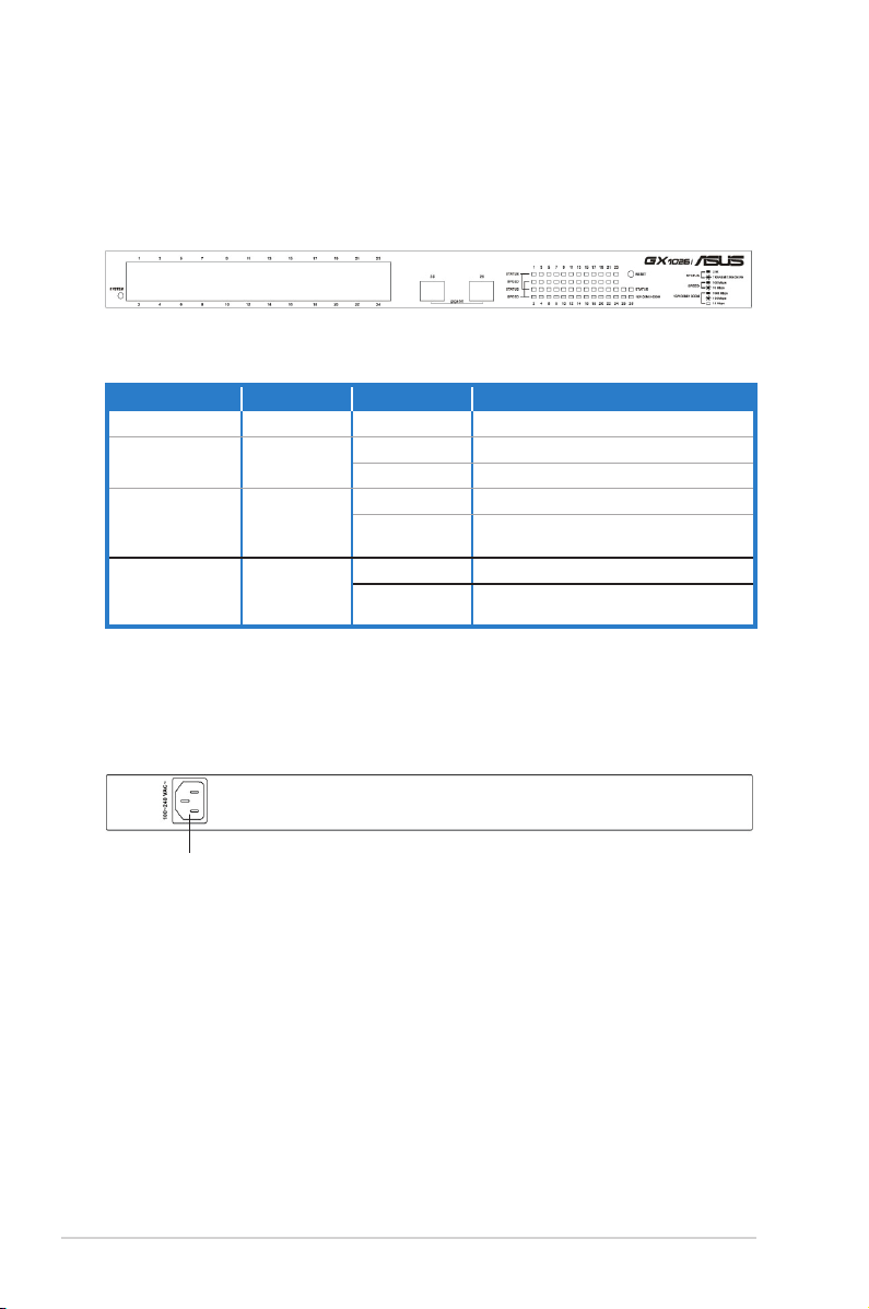
Front panel
The front panel of GX1026i includes 24 10/100Mbps Fast Ethernet ports, 2
10/100/1000Mbps Gigabit Ethernet ports, and LED indicators that show the
working conditions of the switch.
LED indicators
LED Color Status Description
SYSTEM Green ON The power is ON
10/100M LINK
/ ACT
10/100/1000M
LINK / ACT
STATUS Green
Green
Green
ON A link of 100Mbps is established.
Blinking A link of 10Mbps is established.
ON A link of 1000Mbps is established
Blinking
ON System is linking.
Blinking
A link of 10/100 Mbps is
established.
Data is being transmitted or
received.
Rear panel
The rear panel of GX1026i contains the power connector.
Power connector
6 GX1026i Smart Ethernet Switch
Page 7
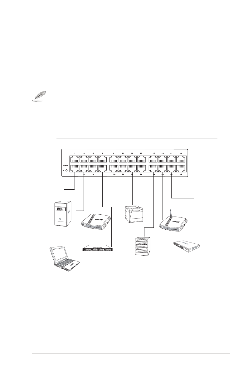
Connecting network devices
12
GX1026i has an auto-MDI/MDIX crossover detection function and provides
plug-and-play capability. Just simply connect your computer and other network
devices to enjoy the switch’s features.
To connect network devices to the GX1026i switch:
1. Connect one end of the Ethernet cable to an Ethernet port on the switch front
panel. Connect the other end to the Ethernet port of the network device. Repeat
this step to connect additional network devices.
• We recommend the use of Category 5 Ethernet straight-through
cables to ensure proper connections between the switch and other
network devices.
• You can use either cross-over or straight-through cables to connect
other network devices such as bridges, switches, hubs, and
repeaters.
Desktop
Notebook
Router
Server
Pri n t e r
Server
NAS
Wireless AP
Switch / Hub
2. Plug one end of the power cable to the power connector on the switch rear
panel, then plug the other end to a power outlet.
3. The Power LED and LAN LED indicators for active Ethernet ports light up when
the switch is powered on and active nodes are connected to the LAN ports.
Refer to the front panel illustration and LED table in page 6 for details.
GX1026i Smart Ethernet Switch 7
Page 8

SmartSwitch Web-Base Controller
The GX1026i contains the SmartSwitch Web-Base Controller, a web-based
preinstalled software, which makes it easier for you to manage and monitor the
switch and the network devices connected to it.
Conguring your LAN
Before running SmartSwitch, you need to congure the Local Area Network (LAN)
settings of your computer. By default, GX1026i IP address is
Subnet Mask is
255.255.255.0
.
Windows® 98/98 SE
192.168.2.1
, and the
1. From your Windows® desktop, click
2. Double-click the
3. Select
be
192.168.2.X
another device.)
4. Set the
, then key in the IP address for the switch. The IP address must
TCI/IP
. (X can be any number between 2 and 254 that is not used by
Subnet Mask
Network
icon, and select the
to
255.255.255.0
>
Start
Settings
. Click OK when nished.
>
Control Panel
Conguration
.
tab.
Windows ® 2000/XP platform
1. From your Windows® desktop, click Start > Control Panel > Network and
Internet Connection > Network Connections.
2. Right-click the Local Area Connection icon, then select Properties.
3. Double-click the Internet Protocol (TCP/IP) item to display the Internet
Protocol (TCP/IP) Properties window.
4. Select the Use the following IP address option, then key in the IP address
for the switch. The IP address must be 192.168.2.X. (X can be any number
between 2 and 254 that is not used by another device.)
5. Set the Subnet Mask to 255.255.255.0. Click OK when nished.
Windows ® Vista platform
1. From your Windows® desktop, click Start > Control Panel > Network and
Sharing Center > Manage Network Connections.
2. Right-click the Local Area Connection icon, then select Properties.
3. Select Internet Protocol version 4 (TCP/IPv4), then click Properties.
4. Select the Use the following IP address option, then key in the IP address
for the switch. The IP address must be 192.168.2.X. (X can be any number
between 2 and 254 that is not used by another device.)
5. Set the Subnet Mask to 255.255.255.0. Click OK when nished.
8 GX1026i Smart Ethernet Switch
Page 9

Logging on to SmartSwitch
To log on to SmartSwitch:
1. In your web browser, enter this IP address: http://192.168.2.1.
2. Enter the default username: admin and password: system. The GX1026i
home page appears. The home page displays quick links to help you easily
congure the features in the switch.
You can change the username and password in Administrator >
Authenticatication Conguration on SmartSwitch.
GX1026i Smart Ethernet Switch 9
Page 10

SmartSwitch Conguration
Using the preinstalled SmartSwitch Web-Base Controller, you can easily access
the quick links and make the necessary congurations. This will make it easy for
you to manage and monitor the switch and the network devices connected to it.
Administrator
Authentication Conguration
This page enables you to change the username and password.
To change the username and password:
1. Click
2. Key in a maximum of 15 alphanumeric characters for both the new username
Administrator > Authentication Conguration
and password. Key in the new password again to conrm.
.
Both the username and password are case sensitve, so take note of
the character case (lowercase or uppercase) that you entered for these
items.
3. Click
10 GX1026i Smart Ethernet Switch
to save the changes.
Update
Page 11

System IP Conguration
This page allows you to set the IP address and subnet mask for the switch. You
can also optionally congure the Gateway IP address; and set the IP address as
static or dynamic IP address.
To access this feature, click
necessary congurations, then click
Administrator
>
System IP Conguration
to save the changes.
Update
, make the
System Status
To view the rmware version and the system settings, click Administrator >
System Status. You can also view the system name from the Comment eld.
To change the system name, simply key in the new system name, then click
Update to save the changes.
Changing the system name will not affect the behavior of the switch.
GX1026i Smart Ethernet Switch 11
Page 12

Load Default Setting
This page enables you to restore the switch’s default settings, except the IP
address, username and password.
To recover the system’s default settings, click
Setting
, then click
Load
.
Administrator
Firmware Update
This page enables you to update the switch’s rmware version.
>
Load Default
To update the rmware:
1. Click
Administrator
2. Key in the password, then key in again to conrm.
3. Click
Update
completed in about 40 seconds.
12 GX1026i Smart Ethernet Switch
>
Firmware Update
, then select the rmware binary le. The uploading process will be
.
Page 13

Reboot Device
To reboot the switch, click
Administrator
>
Reboot Device
, then click
Conrm
.
Port Management
Port Conguration
This page allows you to simultaneously set the operating mode for multiple ports.
To do this, click
port’s operating mode and settings are displayed in the list.
Port Management
>
Port Conguration
, then click
Update
. Each
GX1026i Smart Ethernet Switch 13
Page 14

Port Mirroring
This page enables you to monitor network trafc through setting the destination port
and the source port. To set the destination/source ports, click
Port Mirroring
The source port is the port where all the incoming/outcoming packets are copied
from. The destination port is the port where all the packets will be sent from the
source port.
There are four Port Mirroring methods:
•
Disable
• Rx: The incoming packet of the source port is copied to the destination port.
• Tx: The outgoing packet of the source port is copied to the destination port.
•
Tx & Rx
.
: Disable port mirroring
: Packets at both directions is copied to the destination port.
Port Management
>
Port Mirroring is bandwidth consuming.
To save the settings made on this page, click
14 GX1026i Smart Ethernet Switch
Update
.
Page 15

Bandwidth Control
This page enables you to calculate the actual bandwidth usage for each port.
To calculate a port’s bandwidth:
1. Click
Port Management
2. Key in the numeric values for
3. From the dropdown list, select either
4. Click
its factory default settings, click
to save the settings. To delete all settings and restore the switch to
Update
>
Bandwidth Control
and
Tx Rate
Low
Load Default
.
Rx Rate
or
.
.
for the speed rate.
High
GX1026i Smart Ethernet Switch 15
Page 16

Broadcast Storm Control
This page allows you to control your network’s broadcast or multicast traffic. It
allows you set the threshold for the number of broadcast packets allowed to enter
in each port in one time unit. To save the settings in this page, click
Update
.
VLAN Setting
This page allows you to congure the settings for the Virtual Lan Network (VLAN).
In this page, you can read (or load), add, modify, and remove a VLAN setting.
To load a VLAN setting:
1. Click
2. From the dropdown list, select the VLAN entry that you want to load.
3. Click
16 GX1026i Smart Ethernet Switch
VLAN Setting
to load the VLAN setting.
Read
.
Page 17

To add a VLAN setting:
1. Click
VLAN Setting
2. From the
Mode
.
eld, select either
Port
or
to set the mode if it is a port-
Tag
based or tag-based VLAN. If it is a tag-based VLAN, key in the VLAN ID.
3. From the
4. Click
Add
VLAN Port
to add the VLAN setting.
eld, select the VLAN members.
To modify a VLAN setting:
1. Click
VLAN Setting
.
2. From the dropdown list, select the VLAN entry that you want to modify.
3. Make the necessary changes, then click
to overwrite the settings in the
Modify
VLAN entry.
To remove a VLAN setting:
1. Click
VLAN Setting
.
2. From the dropdown list, select the VLAN entry that you want to delete.
3. Click
Remove
to delete the VLAN entry.
GX1026i Smart Ethernet Switch 17
Page 18

Per Port Counter
There are four kinds of counter for each port:
• Transmit Packet & Receive Packet
• Collision Count & Transmit Packet
• Drop packet & Receive Packet
• CRC error packet & Receive Packet
You can select one out four counters. After clicking the counter mode, the previous
counter value for each port will be ushed. Click
Click
Refresh
to update the counter value.
to clear the counter to 0 (zero).
Clear
18 GX1026i Smart Ethernet Switch
Page 19

Trunk Setting
This page allows you to congure the trunk settings.
To congure the trunk settings:
1. Select one from these four hash algorithms for trafc distribution:
, and
DA
2. Select one or more ports for any of these three trunks:
Trunk3
3. Click
SA & DA
.
Update
. Port ID is the default hash algorithm.
Trunk1, Trunk2
to save the settings.
Port ID, SA
, and
,
GX1026i Smart Ethernet Switch 19
Page 20

QoS Setting
Priority Mode
This page allows you to set the priority for incoming and outgoing packets. You can
set three priority modes for the packets:
• First-In-First-Out: The switch gives equal priority to all packets, and forwards
the packets as soon as they are received.
• All-high-before-low: The switch rst forwards all the packets in high-priority
queue, then forwards those packets in low-priority queue.
• Weight-and-round-Robin: The switch forward a specied number of high
priority packets and then a specied number of low priority packets. The switch
repeats this cycle continuously. The “Low weight” and “High weight” stands for
the “number of packets in low priority queue” and “number of packets in high
priority queue” respectively. The number is only meaningful for weight-andround-robin mode.
“0” is treated as “8” for both weight numbers.
20 GX1026i Smart Ethernet Switch
Page 21

Port, 802.1p, IP/DS based
This page provides three Class of Service (COS) types:
• Port: The packet at this port is unconditionally mapped as high priority.
• 802.1p: 802.1Q tag will be checked. The packet with IP precedence 4~7 and
0~3 is mapped as high priority and low priority respectively.
• IP/DS: The switch checks the TOS or DS eld to decide the priority of the
packet. If a packet hit any of 3 rules, it is treated as a high priority.
GX1026i Smart Ethernet Switch 21
Page 22

TCP/UDP Port based
This page provides Class of Service based on TCP/DUP protocol. In addition to the
well known protocols, this switch supports protocol range to cover a wide range of
protocols. The mask number is used to dene the protocol range. The result of the
calculation is a range of acceptable protocol number.
Example:
The protocol should range from 1~65535 and the mask should be between
1~255. if you ll 7549 in the protocol eld and ll 13 in the mask eld, you will
get the actual protocol numbers which can pass the switch. The calculation
procedure is listed below:
• Transform the mask number into the binary form 1+4+8=13
• Subtract 0, 1, 4, 8, 13 from 7549, you will get result of 7549, 7548, 7545,
7541, 7536
• The protocol number listed above can pass the switch. Selecting “Override”
makes this page conguration override the port based, 802.1p based and IP/
DS based conguration. Click
to save the settings.
Update
22 GX1026i Smart Ethernet Switch
Page 23

Security
MAC Address Filter
In this page, you can assign up to three static MAC addresses to a specied port.
These static MAC addresses will not be aged out from the MAC address table.
“ff ff ff ff ff ff” or “00 00 00 00 00 00” or blank will not be saved to the table. The
conguration procedure is shown below:
• To read the MAC address associated with a port, you should select the port
number and then click
• To specify the MAC address to a port, you should enter the MAC address to the
eld, select a port number and then click
• To ush the MAC address table, you should disable the port binding and then
click
Disable
.
Read
.
to save the settings.
Update
GX1026i Smart Ethernet Switch 23
Page 24

TCP/UDP Filter
There are two types of protocol lter:
The negative list denes the protocol that will be dropped. The positive list denes
the protocol that will be forwarded. To save the settings, click
negative
and
positive
.
Update
.
Conguration
This page enables you to back up or recover the switch's settings. To recover the
switch settings, select the file containing the switch's configurations, then click
Recover
To back up, click
readable text format.
to load the le to the switch.
to save the conguration le. The le will be saved in a
Backup
24 GX1026i Smart Ethernet Switch
Page 25

Miscellaneous
There are three options for Miscellaneous Setting:
VLAN Striding
and click
Update
, and
IGMP Snooping V1 & V2
to save the settings.
. Make the necessary congurations,
Output Queue Aging Time
,
GX1026i Smart Ethernet Switch 25
Page 26

ASUS Contact information
ASUSTeK COMPUTER INC. (AsiaPacic)
Address 15 Li-Te Road, Peitou, Taipei, Taiwan 11259
Website www.asus.com.tw
Technical Support
Telephone +886228943447
Support Fax +886228907698
Software download support.asus.com*
ASUS COMPUTER INTERNATIONAL (America)
Address 44370 Nobel Drive, Fremont, CA 94538, USA
Telephone +15029550883
Fax +15029338713
Website usa.asus.com
Software download support.asus.com*
ASUS COMPUTER GmbH (Germany and Austria)
Address Harkort Str. 25, D40880 Ratingen, Germany
Telephone +49210295990
Fax +492102959911
Online contact www.asus.com.de/sales
Technical Support
Telephone +49210295990
Fax +492102959911
Online support www.asus.com.de/support
Website www.asus.com.de/news
* Available on this site is an online Technical Inquiry Form that you can ll out to contact technical support.
26 GX1026i Smart Ethernet Switch
 Loading...