

Page 1

GigaX Series
Layer 3 Managed Switch
1
User Guide
Page 2

Exxxx
First Edition V1
March 2005
Copyright © 2005 ASUSTeK COMPUTER INC. All Rights Reserved.
No part of this manual, including the products and softw are described in it, may be reproduced,
transmitted, transcribed, stored in a retrieval system, or tran slated into any language in any form or
by any means, except documentation kept by the purcha ser for backup purpo ses, without the
express written permission of ASUSTeK COMPUTER INC. (ASUS) .
Product warranty or service will not be extended if: (1) the pr oduct is rep aired, modif ied or altere d,
unless such repair, modification of alterat ion is author ized in writing by ASUS; or (2) the se rial
number of the product is defaced or missing.
ASUS provides this manual "as is" without warranty of any kind, either express or implied, including
but not limited to the implied warranties or conditi ons of merchantab ility or fitness for a par ticular
purpose. In no event shall ASUS, its directors, officer s, employ ees, or agents be liable fo r any
indirect, special, incidental, or con sequential damages (includ ing damages for loss of profit s, loss of
business, loss of use or data, interr uption of business and the like), even if ASUS has bee n advised
of the possibility of such damages arising from any defect or error in th is manual or produ ct.
Specifications and information contained in th is manual are furnished for informat ional use only,
and are subject to change at any time without notice, a nd should not be construed as a commitment
by ASUS. ASUS assumes no responsibility or liab ility for any errors or inaccuracies that may
appear in this manual, including the products and software described in it.
Products and corporate names appearing in this manual may or may not be regist ered trademarks
or copyrights of their respective companie s, and are used only for iden tification or explanat ion and
to the owners' benefit, without intent to infrin ge.
2
Page 3

GigaX Series L3 Managed Switch User Guide
Federal Communications Commission Statement
This device complies with Part 15 of the FCC Rules. Operation is subject to the
following two conditions:
• This device may not cause harmful interference, and
• This device must accept any interference received including interference
that may cause undesired operation.
This equipment has been tested and found to comply with the limits for a Class
B digital device, pursuant to Part 15 of the FCC Rules. These limits are
designed to provide reasonable protection agai nst harmful interf erence in a
residential installation. This equipment generates, uses and can radiate radio
frequency energy and, if not installed and used in accordance with
manufacturer's instructio ns, may cause harmful int erfere nce to radio
communications. However, there is no gua rantee that interfe rence will not
occur in a particular installation. If this equipment does cause harmful
interference to radio or telev isio n reception , which ca n be det ermine d by
turning the equipment off and on, the user is encouraged to try to correct the
interference by one or more of the follo wing mea sures:
• Reorient or relocate the receiving antenna.
• Increase the separation between the equipment a nd receiver.
• Connect the equipment to an outlet on a circuit different from that to
which the receiver is connected.
• Consult the dealer or an experienced radio/TV technician for help.
WARNING! The use of shielded cables for connection of the monitor to the
graphics card is required to assure compliance with FCC regulations. Changes
or modifications to this unit not expressly approved by the party responsible for
compliance could void the user's aut hority to op erate this equipme nt.
Canadian Department of Communications Statement
This digital apparatus doe s not ex ceed the Class B li mits f or radi o noise
emissions from digital apparatus set out in the Radio Interference Regulations
of the Canadian Department of Communication s.
This class B digital apparatus complies with Canadian ICES-003.
3
Page 4

ASUS contact information
ASUSTeK COMPUTER INC. (Asia-Pacific)
Address: 150 Li-Te Road, Peitou, Taipei, Taiwan 112
General Tel: +886-2-2894-3447
General Fax: +886-2-2894-7798
Web Site: www.asus.com.tw
Technical Support
MB/Others (Tel): +886-2-2890-7121 (English)
Notebook (Tel): +886-2-2890-7122 (English)
Desktop/Server (Tel): +886-2-2890-7123 (English)
Networking (Tel): +886-2-2890-7902 (English)
Support Fax: +886-2-2890-7698
ASUS COMPUTER INTERNATIONAL (America)
Address: 44370 Nobel Drive, Fremont, CA 94538, USA
General Fax: +1-502-933-8713
General Email: tmd1@asus.com
Web Site: usa.asus.com
Technical Support
Support Fax: +1-502-933-8713
General Support: +1-502-995-0883
Notebook Support: +1-510-739-3777 x5110
Support Email: tsd@asus.com
ASUS COMPUTER GmbH (Germany and Austria)
Address: Harkort Str. 25, D-40880 Ratingen, BRD, Germany
General Fax: +49-2102-9599-31
General Email: sales@asuscom.de (for marketing requests only)
Technical Support
Support Hotlines: (Components) +49-2102-95990
(Notebook PC) +49-2102-959910
Support Fax: +49-2102-959911
Support Email: www.asuscom.de/de/support (for online support)
Web Site: www.asuscom.de
4
Page 5

GigaX Series L3 Managed Switch User Guide
Table of Contents
1 Introduction...............................................................................12
1.1 L3 managed features.....................................................12
1.2 Conventions used in this document...............................14
1.2.1 Notations.........................................................14
1.2.2 Typography.....................................................14
1.2.3 Symbols..........................................................14
2 Getting to know the GigaX .......................................................15
2.1 Package contents...........................................................15
2.2 Front Panel.....................................................................16
2.3 Rear Panel.....................................................................18
2.4 Technical specifications.................................................18
3 Quick start guide ......................................................................19
3.1 Part 1 — Installing the hardware....................................19
3.1.1 Installing the switch on a flat surface..............19
3.1.2 Mounting the switch on a rack........................19
3.2 Part 2 — Setting up the switch.......................................20
3.2.1 Connect the console port................................20
3.2.2 Connect to the computers or a LAN...............20
3.2.3 Attach the RPS module ..................................20
3.2.4 Attach the power adapter................................20
3.3 Part 3 — Basic switch setting for management.............22
3.3.1 Setting up through the console port................22
3.3.2 Setting up through the Web interface.............25
4 Management with the Web Interface .......................................27
4.1 Log into Web user interface...........................................27
4.2 Functional layout............................................................28
4.2.1 Menu navigation tips.......................................31
5
Page 6

Commonly used buttons and icons.................31
4.2.2
4.3 System Pages ................................................................32
4.3.1 Management...................................................32
4.3.2 IP Setup ..........................................................33
4.3.3 Administration .................................................34
4.3.4 Reboot.............................................................34
4.3.5 Firmware Upgrade..........................................35
4.4 Physical Interface ..........................................................36
4.5 Route..............................................................................38
4.5.1 Interfaces ........................................................38
4.5.2 Static Route ....................................................40
4.5.3 RIP..................................................................41
4.6 Bridge.............................................................................42
4.6.1 Spanning Tree/Rapid Spanning Tree.............43
4.6.2 Link Aggregation.............................................44
4.6.3 Mirroring..........................................................46
4.6.4 Static Multicast................................................48
4.6.5 IGMP Snooping...............................................48
4.6.6 Traffic Control .................................................49
4.6.7 Dynamic Addresses........................................50
4.6.8 Static Addresses.............................................52
4.6.9 Tagged VLAN .................................................53
4.6.10 Default Port VLAN and CoS............................55
4.6.11 CoS Queue Mapping ......................................56
4.6.12 DHCP Snooping..............................................56
4.7 SNMP.............................................................................58
4.7.1 Community Table............................................58
4.7.2 Host Table.......................................................59
4.7.3 Trap Setting ....................................................60
4.7.4 VACM Group...................................................60
4.7.5 VACM View.....................................................61
4.7.6 USM User........................................................63
4.8 Filters..............................................................................65
4.8.1 Filter Set..........................................................65
6
Page 7

GigaX Series L3 Managed Switch User Guide
Filter Attach.....................................................68
4.8.2
4.9 Security ..........................................................................70
4.9.1 Port Access Control........................................70
4.9.2 Dial-In User.....................................................72
4.9.3 RADIUS..........................................................73
4.10 Statistics Chart...............................................................74
4.10.1 Traffic Comparison .........................................74
4.10.2 Error Group.....................................................75
4.10.3 Historical Status..............................................75
4.11 Save Configuration.........................................................77
5 Console Interface .....................................................................78
5.1 Power On Self Test........................................................79
5.1.1 Boot ROM Command Mode ...........................80
5.1.2 Boot ROM Commands....................................81
5.2 Login and Logout ...........................................................82
5.3 CLI Commands..............................................................82
5.3.1 System Commands ........................................82
5.3.2 Physical Interface Commands........................85
5.3.3 Route Commands...........................................86
5.3.4 Bridge Commands..........................................88
5.3.5 SNMP..............................................................96
5.3.5 Filters Commands.........................................103
5.3.6 Security Commands .....................................107
6 IP Addresses, Network Masks, and Subnets.........................113
6.1 IP Addresses................................................................113
6.1.1 Structure of an IP address............................113
6.1.2 Network classes............................................115
6.2 Subnet masks ..............................................................116
7 Troubleshooting......................................................................118
7.1 Diagnosing problems using IP utilities.........................118
7.1.1 ping...............................................................118
7
Page 8

nslookup........................................................120
7.1.2
7.2 Replacing defective fans..............................................121
7.3 Simple fixes..................................................................123
8 Glossary..................................................................................125
9 Index.......................................................................................134
8
Page 9

GigaX Series L3 Managed Switch User Guide
List of Figures
Figure 1. GigaX L3 managed switch package contents................15
Figure 2. Front panel.....................................................................16
Figure 3. Rear panel......................................................................18
Figure 4. Overview of Hardware Connections ..............................21
Figure 5. Login and IP setup Screen.............................................24
Figure 6. Login Screen..................................................................25
Figure 7. IP Setup..........................................................................26
Figure 8. Configuration manager login screen..............................27
Figure 9. Home page.....................................................................28
Figure 10. Top Frame......................................................................29
Figure 11. Expanded Menu List ......................................................30
Figure 12. Management..................................................................32
Figure 13. IP Setup…......................................................................33
Figure 14. Administration ................................................................34
Figure 15. Firmware Upgrade .........................................................35
Figure 16. Physical Interface...........................................................37
Figure 17. Interfaces .......................................................................39
Figure 18. Static Route....................................................................41
Figure 19. RIP……… ......................................................................42
Figure 20. Spanning Tree................................................................44
Figure 21. Link aggregation.............................................................46
Figure 22. Mirroring page................................................................47
Figure 23. Static Multicast...............................................................48
Figure 24. IGMP Snooping..............................................................49
Figure 25. Traffic Control.................................................................50
9
Page 10

Figure 26.
Figure 27. Static Address ................................................................53
Figure 28. Tagged VLAN.................................................................54
Figure 29. Default Port VLAN and CoS...........................................55
Figure 30. CoS Queue Mapping......................................................56
Figure 31. DHCP Snooping.............................................................57
Figure 32. Community Table...........................................................58
Figure 33. Host Table......................................................................59
Figure 34. Trap Setting....................................................................60
Figure 35. VACM Group..................................................................61
Figure 36. VACM View ....................................................................62
Figure 37. USM User.......................................................................64
Figure 38. Filter Set.........................................................................66
Figure 39. Filter Rule in MAC mode................................................67
Figure 40. Filter Rule in IP mode.....................................................67
Figure 41. Filter Attach ....................................................................69
Figure 42. Port Access Control........................................................71
Dynamic Address ...........................................................51
Figure 43. Dial-In user.....................................................................72
Figure 44. RADIUS..........................................................................73
Figure 45. Traffic comparison..........................................................75
Figure 46. Error group .....................................................................75
Figure 47. Historical Status .............................................................76
Figure 48. Save Configuration.........................................................77
Figure 49. CLI interface...................................................................79
Figure 50. Boot ROM Command Mode...........................................80
Figure 51. SYS commands..............................................................83
Figure 52. Using the ping utility.....................................................119
Figure 53. Using the nslookup utility..............................................120
Figure 54. Loosening the thumbscrew ..........................................121
10
Page 11

GigaX Series L3 Managed Switch User Guide
Figure 55.
Figure 56. Detaching the fan from the module..............................122
Removing the fan module............................................121
List of Tables
Table 1. Front panel labels and LEDs..........................................17
Table 2. Rear panel labels ...........................................................18
Table 3. Technical specifications.................................................18
Table 4. LED Indicators................................................................22
Table 5. Port color description .....................................................29
Table 6. Commonly used buttons and icons................................31
Table 7. Boot ROM commands....................................................81
Table 8. IP address structure.....................................................114
Table 9. Troubleshooting ...........................................................123
11
Page 12

1 Introduction
Congratulations on becoming the owner of the ASUS GigaX L3 managed
switch! You may now manage your LAN (local area network) through a
friendly and powerful user interface.
This user guide tells you how to set up the GigaX L3 managed switch, and
how to customize its configuration to get the most out of this product.
1.1 L3 managed features
• 24 10/100BASE-TX auto-sensing Fast Ethernet ports
• Two 10/100/1000BASE-T auto-sensing Gigabit Ethernet switching ports
• Two small form factor (SFP) Gigabit interface conve rter (GBIC) sl ots
• Automatic MDI/MDIX support for 10/100BASE-TX and
10/100/1000BASE-T ports
• Layer 3 switching for IP packets
• 2K IP address cache with hardware-accelerated forwarding
• Static route
• RIP v1, v2
• Compliant with 802.3u, 802.3z and 802.3ab specifications
• 802.1D transparent bridge/spanning tree protocol
• 802.1w RSTP (Rapid Spann ing Tree P roto col)
• IEEE 802.1x authentication (with dynamic VLAN assignment)
• RADIUS (Remote Authentication Dial-in User Service)
• 8K MAC address cache with hardware-assisted aging
• 802.3x flow control
• 802.1Q-based tagged VLAN , up to 25 5 VLANs
• 802.1p class of service, 4 queues per port
• IGMP snooping support
• 802.3ad link aggregation (trunking), up to 6 trunk groups
• Port Mirroring
• Access Control List
• RMON: support 4 groups (1, 2, 3, 9)
• SNMP v1, v2, v3
12
Page 13

GigaX Series L3 Managed Switch User Guide
• MIB-II
• Enterprise MIB for PSU, fan, and sy stem tem perature, v oltage
• Telnet or SSH remote login
• FTP for firmware update and configuration backup
• DHCP snooping support
• Syslog support
• Command Line Interpreter through con sole , telnet and SSH
• Web GUI
• LEDs for port link status
• LEDs system, redundant power supply (RPS), and fa n status
13
Page 14

1.2 Conventions used in this document
1.2.1 Notations
• Acronyms are defined the first time they appear in text and in the
glossary.
• For brevity, the GigaX switch is referred to as “the switch.”
• The terms LAN and network are used interchangeably to refer to a group
of Ethernet-connected computers at one site.
1.2.2 Typography
• Italics are used to present the parameters for the command line
interpreter.
• Boldface type text is used for items you select from menus and
drop-down lists, and text stri ngs you ty pe when prom pted by the pr ogram.
1.2.3 Symbols
This document uses the following icons to call your attention to specific
instructions or explanations.
Provides clarification or additional information on the current
Note
topic.
Definition
WARNING
14
Explains terms or acronyms that may be unfamiliar to many
readers. These terms are also included in the Glossary.
Provides messages of high importance, including messages
relating to personal safety or system integrity.
Page 15

GigaX Series L3 Managed Switch User Guide
2 Getting to know the GigaX
2.1 Package contents
The GigaX switch package comes with the following items:
• 24-port L3 managed switch
• AC Power cord
• Null modem cable for console interface (DB9)
• Rack installation kit (two brackets with six #6-32 screws)
• USB cable for console interface
• Installation CD-ROM
• Quick installation guide
Figure 1. GigaX L3 managed switch package contents
15
Page 16

2.2 Front Panel
The front panel includes LED indicators that show the system, RPS, fan,
and port status.
Figure 2. Front panel
16
Page 17

GigaX Series L3 Managed Switch User Guide
Table 1. Front panel labels and LEDs
Label Color Status Description
SYSTEM
Amber On Abnormal temperature or voltage
Off No power
RPS
10/100 ports
10/100/1000
port status
10/100/1000
port speed
Console USB USB port for console management
Console RS232 RS-232 serial port for console management
Green On The PSU is working properly and the switch
Amber On The PSU is abnormal and the switch is
Off No power at all (system LED is also off), RPS
Green On Both fans are working properly FAN
Amber On Both or either one of the fans stopped
Off No Ethernet link
Amber
Green On Link (RJ-45 or SFP) is present; port is
Flashing Data is being transmitted/received
Off No Ethernet link
Amber
Green On 1000Mbps
Amber On 100Mbps
Off 10Mbps
On Unit is powered on Green
Flashing Self-test, INIT, or downloading
has a good redundant power supply
powered by RPS
does not work properly or not installed
(system LED is on)
On Ethernet link is established Green
Flashing Data is being transmitted/received
On Link is present, but port is disabled either
manually or by spanning tree
Flashing Port is in one of the STP blocking, listening
and learning state
enabled
On Link is present, but port is disabled either
manually or by spanning tree
Flashing Port is in one of the STP blocking, listening
and learning state
17
Page 18
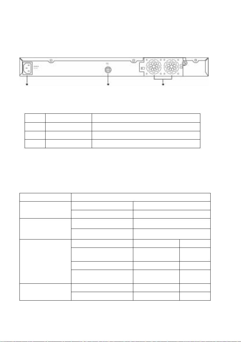
2.3 Rear Panel
The switch rear panel contains the ports for the data and power
connections.
Figure 3. Rear panel
Table 2. Rear panel labels
No. Label Description
1 Power Connector Connects to the supplied power cord
2 RPS Redundant Power Supply connector
3 FAN1 – FAN2 Replaceable system fans
2.4 Technical specifications
Table 3. Technical specifications
Physical Dimensions 43.5mm(H) X 444 mm(W) X 265mm(D)
Input Consumption Power
100-240V AC/2.5A 50-60Hz < 90 watts
Supply (RPS)
Environmental Ranges
Input Output Redundant Power
100-240V AC/1.8A 50-60Hz 12V DC/12.5A
Operating Storage
Temperature -10 to 50 (14 to ℃
122 )℉
Humidity 15 to 90% 0 to 95%
Altitude up to 10,000 ft
(3,000m)
Dimensions Voltage and Current Speed: Replaceable Fans
40 x 40 x 20 mm 12VDC, 0.13A 8200RPM
18
-40 - 70℃
(-40 to 158 )℉
40,000 ft
(12,000m)
Page 19

GigaX Series L3 Managed Switch User Guide
3 Quick start guide
This section provides the basic instructions to set up the GigaX
environment. Refer also to the GigaX Series Installation Guide.
Part 1 shows you how to install the GigaX on a flat surface or on a
rack.
Part 2 provides instructions to set up the hardware.
Part 3 shows you how to configure basic settings on the GigaX.
Obtain the following inf orma tion fro m your net work ad ministrat or bef ore
proceeding:
IP address for the switch
Default gateway for the network
Network mask for this network
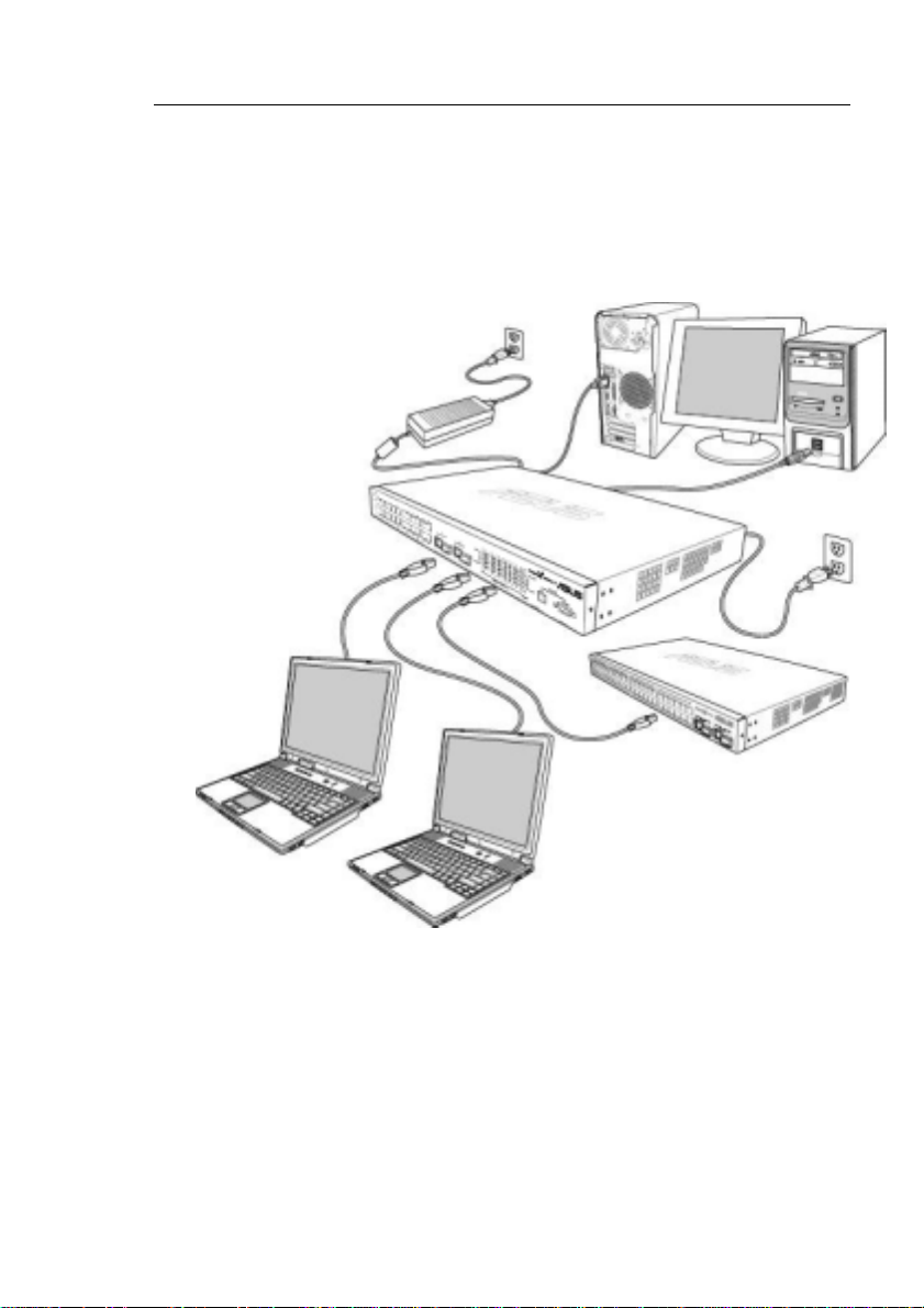
3.1 Part 1 — Installing the hardware
Connect the device to the power outlet, and your computer or network.
Figure 4 illustrates the hardware connections.
3.1.1 Installing the switch on a flat surface
The switch should be installed on a level surface that can supp ort the
weight of the switches and their accessories. Attach four rubber pads on
the marked location on the bottom of t he switch.
3.1.2 Mounting the switch on a rack
1. Attach brackets to each side of the switch and make the posts insert
to the switch.
2. Insert and tighten two screws to securely attach the bracket to the
rack on each side.
19
Page 20

3.2 Part 2 — Setting up the switch
Connect the device to the power outlet, and your computer or network. See
Figure 4.
3.2.1 Connect the console port
For console management, use an RS232 (DB9) or a USB cable to
connect the switch. If you want to use WEB interface, connect your PC
to the switch using the Ethernet cable.
3.2.2 Connect to the computers or a LAN
You can use Ethernet cable to connect computers dire ctly to the switch
ports. You can also conne ct hubs/ switch es to the switch po rts by Et hernet
cables. You can use either the crossover or straight -through Ethernet cable
to connect computers, hubs, or switches.
Use a twisted-pair Category 5 Ethernet cable to connect the
1000BASE-T port. Otherwise, the link speed can not reach
1Gbps.
3.2.3 Attach the RPS module
Connect your RPS module to the RPS jack and make sure the other end of
the RPS is connected to the power cord. Connect to the power cord to a
grounded power outlet.
3.2.4 Attach the power adapter
1. Connect the AC power cord to the POWER receptacle on the back
of the switch and plug the other end of the power cord into a wall
outlet or a power strip.
2. Check the front LED indicators with the descri ption in Table 4. If the
LEDs light up as described, the switch hardware is working
properly.
20
Page 21
GigaX Series L3 Managed Switch User Guide
Console
Management
RPS
Cat 5 Ethernet cables
LAN computers
RS-232
Figure 4. Overview of Hardware Connections
USB
Expansion
hub/switch
21
Page 22

Table 4. LED Indicators
No. LED Description
1 System Solid green indicates that the device is turned
2 Switch ports
[1] to [26]
3 RPS Solid green indicates that the device has
4 Fan Solid green indicates that all fans work
on. If this light is off, check if the power
adapter if attached to the switch and plugged
into a power source.
Solid green indicates that the device can
communicate with the LAN, or flashing when
the device is sending or receiving data from
your LAN computer.
successfully installed an RPS module.
properly
3.3 Part 3 — Basic switch setting for
management
After completing the hardware connections, configure the basic settings for
your switch. You can manage the switch using the following methods:
• Web i nterface: the switch has a set o f pages to allow you to man age it
using Java
®
-enabled IE5.0 or higher version.
• Command Line Interface: use console port to manage the switch.
3.3.1 Setting up through the console port
1. Use the supplied crossover RS-232 cable to connect to the console
port on the front of the switch. This port is a male DB-9 connector,
implemented as a data terminal equipment (DTE) connection.
Tighten the retaining screws on the cable to secure it on the
connector. Connect the other end of the cable to a PC running
terminal emulation software. e.g Hyper Terminal.
2. Use the supplied USB cable to connect t o a PC. You have to install
the USB driver from the switch CD-ROM before the USB can work
properly. The USB drivers will simulate an additional COM port
under Windows ME/2K/XP OS.
22
Page 23

GigaX Series L3 Managed Switch User Guide
3. Make sure the settings of your terminal emulation software as
follows:
a) Choose the appropriate serial port number
b) Set the data baud rate to 9600
c) Set the data format to no parity, 8 data bits and 1 stop bit
d) No flow control
e) Set VT1000 for emulation mode
4. After setting up the terminal, you can see the prompt “(ASUS)%” on
the terminal.
5. Type “login” to access the command line interface. The default u ser
name is “admin”. Skip the password by pressing <Enter>.
You can change the password at any time through CLI (see
section 5.3.1). To protect your switch from unauthorized
6. Follow these steps to assign an IP address to the switch:
a) Type “l3 interface ip sw0 <your ip address> <your network
mask>”. For example, if your switch IP is 192.168.10.1 and the
network mask is 255.255.255.0. Then you should type “l3
interface ip sw0 192.168.10.1 255.255.255.0”.
access, you must change the default password as soon as
possible.
b) If the switch has to be managed across networks, then a
default gateway or a static route entry is required. Type “l3
route static add 0.0.0.0 <your network gateway IP> 0.0.0.0 1”
as your default route entry, as shown in Figure 5.
23
Page 24
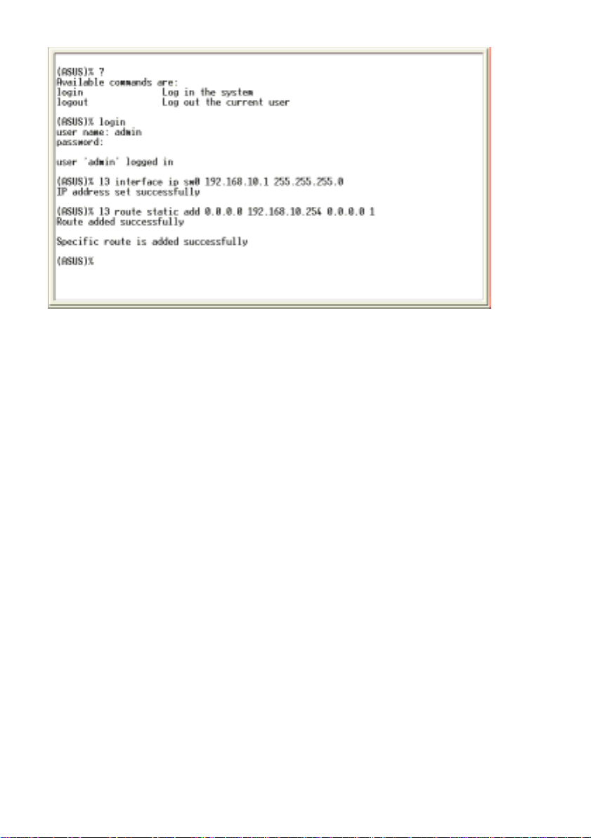
Figure 5. Login and IP setup Screen
24
Page 25
GigaX Series L3 Managed Switch User Guide
3.3.2 Setting up through the Web interface
To successfully connect your PC to the switch, your PC must a valid IP in
your network. Contact your network administrator to obtain a valid IP for the
switch. If you wish to change the def ault IP ad dress of t he switch, f ollo w
section 3.3.1 to change the IP ad dress. Si nce the switch do es not sup port
DHCP client function, a valid static IP for the switch is necessary to use
Web interface.
1. It is not necessary to login Web interface at the first time to use Web
interface because the default configuration for Web access
authentication is disabled. To secure the system configuration,
please enable the authentication function at the “Administration”
page under “System” category. Skip step 2 if the authentication is
disabled.
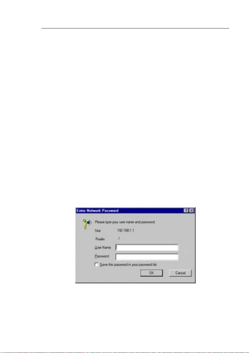
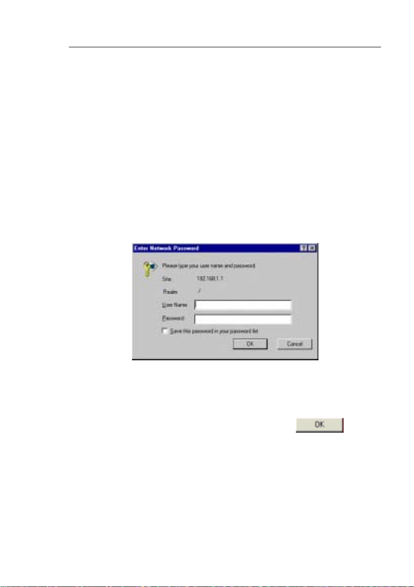
2. At any PC connected to the network that the switch can acce ss ,
open your Web browser (Internet Explorer), and type the following
URL in the address/location box, and press <Enter>:
http://192.168.1.1
This is the factory default IP address of the switch.
A login screen appears, as shown in Figure 6.
Figure 6. Login Screen
25
Page 26
Enter your user name and password, and then click
to enter
the Configuration Manager. Use the foll owing def aults the first ti me
you log into this interface:
Default User Name: admin
Default Password: (no password)
You can change the password at any time (see section
5.3.1 System Commands).
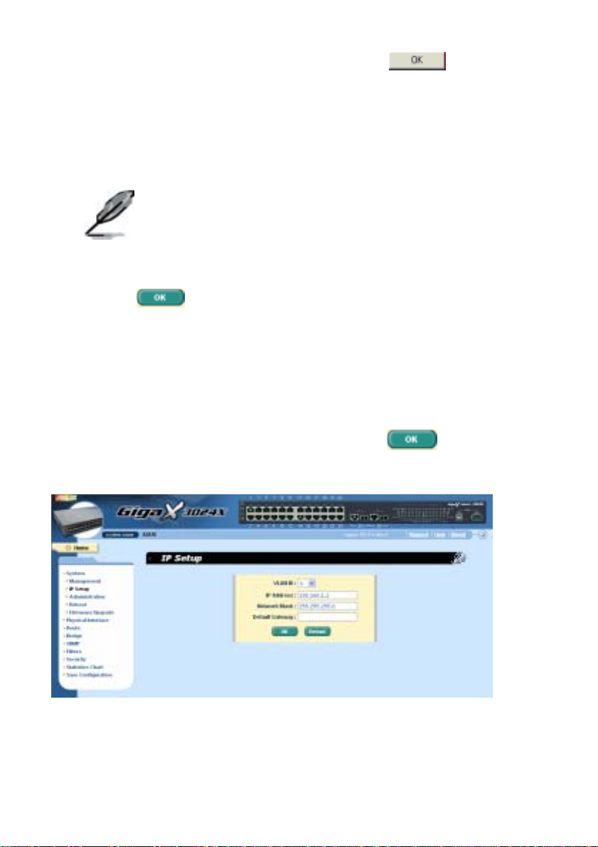
3. To setup a new IP address, click “System”, then “IP Setup” (see
Figure 7). Fill in the IP address, network mask and default gateway,
then click
.
4. If your new address is different from the default, the browser can not
update the switch status window or retrieve any page. This is
normal. You have to retype the new IP address in the
address/location box, and press <Enter>. The WEB link returns.
5. To enable authentication for Web access, click “Administration” on
the menu list, then select “Enabled” to start the protection.
A login window appears i mmedi ately afte r you cl ick
figures on the next page.
Figure 7. IP Setup
26
. See the
Page 27
GigaX Series L3 Managed Switch User Guide
4 Management with the Web Interface
The switch provides Web pages that allow switch management through the
Internet. The program is designed to work best with Microsoft Int ernet
Explorer® 5.5, or later versions. NOTE: Netscape is not supported.
4.1 Log into Web user interface
1. From a PC, open your web browser, type the followin g in the web
address (or location) box, and press <Enter>:
http://192.168.1.1
This is the factory default IP address f or t he switch. A l ogin screen
displays, as shown in Figure 8.
Figure 8. Configuration manager login screen
Log in is not required if you don’t enable access authentication
2. Enter your user name and password, then click
Use the following defaults the first time y ou log int o the pro gram. You
can change the password at any time throug h CLI interf ace (see
section 5.3.1).
Default User Name:
Default Password:
27
admin
<no password>
.
Page 28
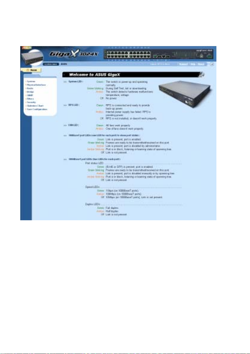
The home page appears each time you log into the program. (See Figure
9.)
Figure 9. Home page
4.2 Functional layout
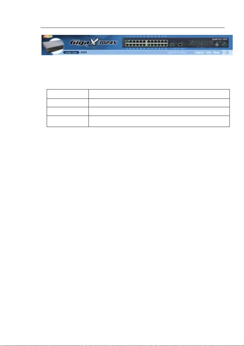
Typical web page consists of three separate frames. The top frame has a
switch logo and front panel as shown in Figures 10. This frame remains on
the top of the browser wind ow all the t imes and up dates the LE D st atus
periodically. See Table 4 for the LED definition s. See Table 5 for the col or
status description.
28
Page 29
GigaX Series L3 Managed Switch User Guide
Figure 10. Top Frame
Table 5. Port color description
Port Color Description
Green port Ethernet link is established
Black No Ethernet link
Amber port Link is present but port is disabled manually or by spanning tree
Clicking on the port icon of the switch displays the port configurat ion in the
lower right frame.
The left frame, a menu frame a s shown in Figure 1 1, contai ns all the
features available for switch configurat ion. These features are groupe d into
categories, e.g. System, Bridge, etc. You can click on any of these to
display a specific configuration page.
29
Page 30
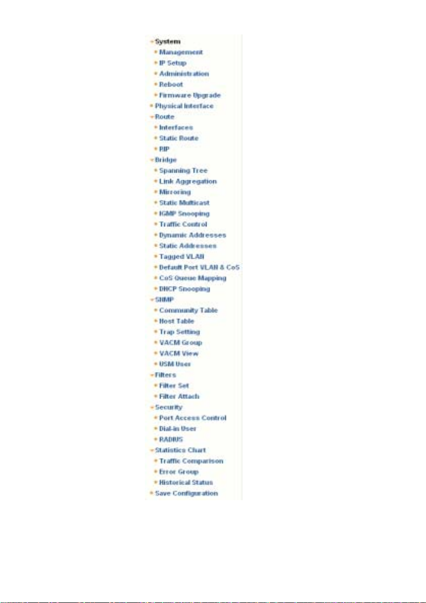
30
Figure 11. Expanded Menu List
Page 31

GigaX Series L3 Managed Switch User Guide
The above frame displays configuration pages or graphics for the
statistics. See section 4.3 for details.
4.2.1 Menu navigation tips
• To expand a group of related menus, click on the correspondi ng
group name. The sign will change to after expansion.
• To contract a group of related menus: click on the corresponding
group name. The
sign will appear next to the group name.
• To open a specific configurat ion page, click on th e desire d menu
item.
4.2.2 Commonly used buttons and icons
The following table describes the function for each button and icon used in
the application.
Table 6. Commonly used buttons and icons
Button/Icon Function
Stores any changes you have made on the current page.
Adds the existing configuration to the system, e.g. a static MAC
address or a firewall ACL rule and etc.
Modifies an existing entry
Modifies the existing configuration in the system, e.g. a static route
or a filter ACL rule and etc.
Deletes the selected item, e.g. a static route or a filter ACL rule and
etc.
Re-displays the current page with updated statistics or settings.
31
Page 32

4.3 System Pages
System pages include management, IP setup, administration, reboot, and
firmware update function.
4.3.1 Management
The Management page contain s the foll owing i nformation:
Model Name: product name
MAC Address: switch MAC address
System Name: user assigned name to identify the system (editable)
System Contact (editable)
System Location (editable)
To save any changes and make it effective immediately, click
Use
to refresh the setting, as shown in Figure 12.
Figure 12. Management
.
32
Page 33

GigaX Series L3 Managed Switch User Guide
4.3.2 IP Setup
The switch supports only static IP assignment. The IP Setup page contains
the following editable informati on:
VLAN ID: Specify a VLAN ID to system management interface. It is
necessary to be within the same VLAN for management usages.
IP Address: Assign a static IP address to the switch management
interface.
Network Mask
Default Gateway
To save any changes and make it effective immediately, click
Use
to refresh the setting, as shown in Figure 13.
Figure 13. IP Setup
.
33
Page 34

4.3.3 Administration
The Administration pa ge allows you enab le or disable the a uthenticat ion
for web user by password protection. The default setting for web access
does not require any authentication.
To save any changes and make it effective immediately, click
Use
to refresh the setting, as shown in Figure 14. When you
enable the password protection, you have to login again immediately.
You can change the password at any time through the CLI
interface.
Figure 14. Administration
.
4.3.4 Reboot
The Reboot page contains a button. Clicking the button reboots
the system.
Rebooting the system stops the network traffic and
terminates the Web interface connection.
34
Page 35

GigaX Series L3 Managed Switch User Guide
4.3.5 Firmware Upgrade
The Firmware page contains the following information:
Hardware Version: shows the hardware revision number.
Boot ROM Version: shows the v ersion of t he boot code
Firmware Version: shows the current running firmware version. This
number will be updated after the firmware update.
Enter the firmware location into the firmware space dire ctly, or click
to choose the file name of the firmware from prompt window.
Click
to update the switch firmware. See Figure 15 for reference.
Clicking the upload button loads the assigned firmware to the
switch, then reboot system after a successful firmware
update. You have to re-login to Web interface again
Figure 15. Firmware Upgrade
35
Page 36

4.4 Physical Interface
The Physical Interface displays the Ethe rnet port statu s in real time. You
can configure the port in following fields:
Port: select the port to configure
Admin: disable/enable the port
Mode: set the speed and duplex mode
Flow Control: enable/disable 802.3x flow control mechanism
Port Status Window: displays the fol lowing inf ormation f or each p ort
a) Link status: the link speed and duplex for an existing link,
otherwise link is down
b) State: the STP state
c) Admin: the setting value to disable or enable the port
d) Mode: the setting value for link speed and duplex mode
e) Flow Control: the setting value to enable or disable 802.3x
flow control mechanism
Select the corresponding port number and configure the port setting, then
click on the
of the display window. However, the new settings do not take effect until
the “Save Configuration” is executed.
36
button. The field you change will update t he conte nt
Page 37

GigaX Series L3 Managed Switch User Guide
Figure 16. Physical Interface
37
Page 38

4.5 Route
This command group offers L3 interface and route entry configuration
4.5.1 Interfaces
Generally, Layer 3/routed interfaces are used to route traffic between
the VLAN, this is so-called inter-VLAN routing. That is, different VLANs
exchange data with going through Layer 3 interfaces and need not an
external router.
This switch performs Layer 3 switching only for IP protocol. To enable
Layer 3 switching on a specific interface, the following information must
be configured:
Name: the UNIQUE name used for managing Layer 3 interfaces
under CLI console
Type: VLAN type interface is virtual interface, which is VLAN-bind;
where Port type interface is routed port base. One of the interface
types must be specified
VLAN: the interface associated VLAN (range 1-4000), this VLAN
should have been created as well as assigned with port member in
Layer 2. One VLAN ID can only be assigned to one interface
Routed port: where the traffic should be destined to. Routed port
does not perform Layer 2 functions. Not e that you cannot configure
a mirror-to port, trunk port, or 802.1x authentication unauthorized
(auto/force) port as a routed port simultaneously. Routed port will
automatically become non-STP port when STP/RSTP process has
been enabled
IP address: the interface IP address
Subnet mask: the interface subnet mask
Status: interface up/down (Layer 3 switching works only amongst
the running up interfaces)
38
Page 39

GigaX Series L3 Managed Switch User Guide
Select the corresponding interface and configure the interface
parameters. To save any changes and make it effective
immediately, click
field you changed will update the content in the display window.
By default, Layer 3 switching is disabled. You have to create and
activate Layer 3 interface(s) before enable Layer 3 switching. Up to 32
Layer 3 interfaces can be created in this switch.
Interface "sw0" is the system interface, which is default created by the
system and cannot be removed.
. Use to refresh the setting. The
Check the [Remove] checkbox and click
remove an interface from the select list.
Click
the settings to current value.
to make the setting effective. Click to refresh
Figure 17. Interfaces
if you want to
39
Page 40

4.5.2 Static Route
Static routing is the simplest form of network routing. It makes available
to a switch/router to forward packets from predetermined ports through
a predictable path into and out of a network. Static routing is solid, but
does not address to the fluctuation in the network, therefore, it might
result in destination net unreachable.
To create a static route entry, you have to configure the following
information:
Destination: Input destination IP address.
Netmask: Input subnet mask of the destination.
Gateway: Input gateway IP address.
Metric: Metric/cost for the destination (1-15).
Static routing is easy to set up and be managed particularly in small
networks. But, it needs additional planning and management in
advanced. Meanwhile, it does not scale well in large networks.
If a match is not found in the routing table for the destination IP address,
then a default route is required. A default route is somewhile called the
"route of last resort". It is the last route tried when all other routes fail.
Since routing has longest prefix match behavior, the default route has
the fewest number of network bits matching and is therefore less
specific. A default route is always configured with both 'Destination' and
'Netmask' as the value of '0.0.0.0'.
Click on
the new added entry shows in the list. You can remove the existed route
by clicking the button, then clicking on
removed will be saved in configuration file immediately.
Click
the settings to current value.
40
when you add a new static route and you will see
. The route added and
to make the setting effective. Click to refresh
Page 41

GigaX Series L3 Managed Switch User Guide
Figure 18. Static Route
4.5.3 RIP
The Routing Information Protocol (RIP) is documented in RFC 1058,
RFC 1388
protocol that exchange routing information using UDP packets.
and RFC 1723. In short, RIP is a distance-vector routing
RIP configuration includes the following information:
RIP process: enable/disable. RIP advertisements are sent and
received only when the RIP process is enabled.
RIP version: v1/v2/both. To specify what RIP Version packets are to
be sent and received.
RIP interfaces: To specify which routing entry should be advertised
along the networks. Note that only the running up Layer 3
interface(s) (in connected status) will be able to advertise routing
information,while the interface(s) in disconnected and down status
will not.
41
Page 42

By default, RIP process is disabled and two of RIP Versions are
assigned for the switch. All Layer 3 interfaces are classified as RIP
enabled interfaces.
Once the RIP process has been enabled, the current state of the active
process will be displayed. You can click to refresh the
updated status.
Click
Click
to change the RIP interfaces setting.
to make the setting effective.
Figure 19. RIP
4.6 Bridge
The Bridge page group contains most layer 2 configurations, like link
aggregation, STP....etc..
42
Page 43

GigaX Series L3 Managed Switch User Guide
4.6.1 Spanning Tree/Rapid Spanning Tree
The configuration page for S panning Tree Protocol can disable a nd enable
the feature in runtime. This p age consi sts of thre e part s.
The first part shows the root information. It tells user the STP setting about
the root switch.
The second part is the STP setting. The following options are availabl e:
Disable/STP Enabled/RSTP Enabled: Turn the STP/RSTP off/on.
When you turn the STP/RSTP on, STP/RSTP will use the f ollowing
settings if the switch is the root switch.
Hello Time: the interval betwee n the generation of confi guration BPDU
Max Age: a timeout value to be used by all Bridges in the LAN
Forward Delay: a timeout value to be used by all bridge s in the LAN
Bridge Priority: the switch priority in the LAN
The third part is the port setti ng. It contain s a disp lay window to show the
current configuration for each po rt. You cli ck
setting for STP/RSTP. The following fields are available:
Port: select the corresponding port to configure
Priority: the port priority in the switch. Low numeric value indicates a
high priority. The port with lower priority is more likely to be blocked by
STP if a network loop is detected. The v alid value is from 0 to 240.
Cost: the valid value is from 1 to 200000000. The higher cost is more
likely to be blocked by STP if a network loop is detected.
FastLink: make the port in forwarding state when a link comes up, then
the port will participate STP resolutions.
Edge Port: All ports are set to be edge ports by default. Edge port
becomes STP port when BPDU is received. Also, it takes very short
time for an edge port to be in forwarding state.
43
to change the port
Page 44

Point to Point: Auto/Yes/No. A full duplex link is considered as a point
to point link. Otherwise, it is a shared link. Point to point link may have
less convergence time. Auto is recommended in most cases.
Click
the current value.
to effect the settings. Click to refresh the settings to
Figure 20. Spanning Tree
4.6.2 Link Aggregation
The page configures the link aggregation group (port trunking). Th e
switch can have 6 link aggregation groups.
Show Trunk: Select “Add a new Trunk” for a new created group. Or
select an existed group to displ ay on the foll owing fie lds and port
icons.
44
Page 45

GigaX Series L3 Managed Switch User Guide
Port Selection Criterion: the al gorith m to dist ribute packets among t he
ports of the link aggregation group according to source MAC address,
destination MAC address, source and destination MAC address,
source IP address, destination IP address, or source and destination
IP address.
Name: the group name.
Trunk ID: a number to identify the trunk group besides the group
name.
LACP: Enable/Disable LCAP on selected trunk. LACP mode is fixe d to
be Active.
Remove Trunk: Remove the selected trunk.
Port Icons: these port icons are listed in a way like the front panel. You
have to click on the icon the select the group members. Th e port can
be removed from the group by clicking t he selecte d port ag ain.
Click
to make the setting send to the switch (HTTP serv er). Cli ck
to refresh the settings to current value. To make the configuration
effective, go to “Save Configuration” page, then click
.
You have to check the runtime l ink spee d and du plex mode t o make sure
the trunk is physically active. Go t o Physical Interface and check the link
mode in the runtime statu s window f or the t runk port s. If all th e trunk
members are in the same speed and full duplex mode, then the trunk group
is set up successfully. If one of the members is not in the same speed or full
duplex mode, the trunk is not set co rrectly. Che ck the li nk part ner a nd
change the settings to have the same speed and full duplex mode fo r all
the members of your trunk group.
• All the ports in the link aggregation group MUST operate
in full-duplex mode at the same speed.
• All the ports in the link aggregation group MUST be
configured in auto-negotiation mode or full duplex mode.
• This configuration will make the full duplex link possible. If
you set the ports in full duplex force mode, then the link
partner MUST have the same setting. Otherwise the link
45
Page 46

aggregation could operate abnormally.
• All the ports in the link aggregation group MUST have the
same VLAN setting.
• All the ports in the link aggregation group are treated as a
single logical link. That is, if any member changes an
attribute, the others will change too. For example, a trunk
group consists of port 1 and 2. If the VLAN of port 1
changes, the VLAN of port 2 also changes with port 1.
Figure 21. Link aggregation
4.6.3 Mirroring
Mirroring, together with a network traffic analyzer, helps you monitor
network traffics. You can monitor the selected ports for egress or
ingress packets.
Mirror Mode: Enables or disables the mirror function for the selected
group.
46
Page 47

GigaX Series L3 Managed Switch User Guide
Monitor Port: Receives the copies of all t he traff ics in the select ed
mirrored ports.
GigaX 3024X has only one monitor port. The port can monit or 24
Fast Ethernet ports and two Gigabit p orts.
The monitor port can not belong to any link aggregation group.
The monitor port can not operate as a normal switch port. It does
not switch packets or do address learning.
Click to make the setting send to the switch (HTTP serv er). Cli ck
to refresh the settings to curre nt value.
Figure 22. Mirroring page
47
Page 48

4.6.4 Static Multicast
This page can add multicast addresses into the multicast table. The switch
can hold up to 256 multicast entries. All t he ports in t he group will f orward
the specified multicast packets to other ports in the group.
Show Group: selects “Add a new Group” to enter a new entry. Or
select an existing group address to display
MAC Address: selects the multicast address
VLAN: selects the vlan group
CoS: assigns the priority for Class of Service
Click
settings to current value.
to make the setting effective. Click to refresh the
Figure 23. Static Multicast
4.6.5 IGMP Snooping
IGMP snooping helps reduce the multicast traffics on the network by
allowing the IGMP snooping function to be turned on or off. When turned
on, the switch snoops the IGMP packets and puts the new group into the
multicast table. However, if the st atic e ntries occu py all 256 spaces, t he
IGMP snoop does not work normally. The switch only allows 256-layer 2
multicast group.
48
Page 49

GigaX Series L3 Managed Switch User Guide
Figure 24. IGMP Snooping
4.6.6 Traffic Control
Traffic control prevents the switch bandwidth from flooding packets
including broadcast packets, multicast packets and the unicast packets
because of destination address lookup failure. The limit number is a
threshold to limit the total num ber of the checked type packet s. For
example, if broadcast and multicast a re enabled, the total traffi c amount fo r
those two types will not ex ceed the limit value. Cli ck
new configuration. To make the configuration effe ctive, go to “Save
Configuration” page, then click
49
.
to save th e
Page 50

Figure 25. Traffic Control
4.6.7 Dynamic Addresses
This page displays the result of dynamic MAC address lookup by port,
VLAN ID, or specified MAC address. The dynamic address is the MAC
address learned by switch, it will age out from the address table if the
address is not learned again during the age time. User can set the age time
by entering a valid number from 10 to 1,000,000 in second s. Then click on
to save the new age value. To make the configuration effectiv e,
please go to “Save Configuration” page, then click on
You can look up MAC addresses by checking the port, VLA N ID, or/and
MAC address, then click on
the result of the query.
50
. The address window will display
.
Page 51

GigaX Series L3 Managed Switch User Guide
Figure 26. Dynamic Address
51
Page 52

4.6.8 Static Addresses
You can add a MAC address i nto the swi tch address t able. T he MAC
address added by this way will not age out from the address table. We call
it static address.
MAC Address: enter the MAC address
VLAN ID: enter the VLAN ID that the MAC belongs
Port Selection: select the port which the MAC belongs
Discard: you can do packet filtering when the MAC address appears in
the packets as destination address, source address, or either of them.
Click on the
above information. Then you will see the new added entry shows in the
address window. You can remove the existed address by selecting the
entry with the mouse, then clicking on
updates the existed MAC address entries. Click
Click
configuration effective, plea se go to “save conf igurat ion” pa ge, then cli ck
to refresh the settings to current value. To make the
.
when you create a new static MAC address by the
. The button
to save effective.
52
Page 53

GigaX Series L3 Managed Switch User Guide
Figure 27. Static Address
4.6.9 Tagged VLAN
You can set up to 255 VLAN groups and show VLAN group in this page.
There is a default VLAN created by the switch. It cann ot be remov ed at all.
This feature prevents the switch from malfuncti ons. You can rem ove any
existed VLAN except the def ault VLAN.
You can assign the port to be a tagged port or an untagged port by toggling
the port button. There are three typ es of butt on disp lays:
“U” type: untagged port that will remove VLAN tags from the
transmitted packets.
“T” type: All packets transmitted from this port will be tagged.
“blank” type: This port is not a member of the VLAN grou p.
If one untagged port belongs to two or more VLAN groups at the same time,
it will confuse the switch and cause flooding traffics. To prevent it, the
switch only allows one untagged port belongs to one VLAN at the same
time. That is, the untagged port belongs to the VLAN group which is called
“PVID” and configured in the “Default Port VLAN & CoS” page. If you want
to assign an untagged port from one VLAN to another, you have to remove
it from the original VLAN, or change it to be tagged i n the origi nal VLA N
first.
Show VLAN: select the existed VLAN to display or select “Add a new
VLAN” to create a new VLAN gro up
Name: the VLAN name
DHCP Snoop: Enable or disable DHCP snooping on this VLAN.
VLAN ID: this field requires user to enter the VLAN ID when a new
VLAN is created
Remove VLAN: Remove an existed VLAN. This field disappears in
VLAN creation page.
Click on
effective, go to “Save Configuration” page, then click on
53
to save the configuration. To make the configuration
.
Page 54

Figure 28. Tagged VLAN
54
Page 55

GigaX Series L3 Managed Switch User Guide
4.6.10 Default Port VLAN and CoS
Some VLAN tag related field settings fo r each port are included in t his page.
It includes:
Port: select the port to configure
PVID: port-based VLAN ID. Every untagged packet received from this
port will be tagged with this VLAN group ID
CoS (Class of Service) value: eve ry untagge d packet received f rom
this port will be assigned to this CoS in the VLAN tagged
Click on
to save the configuration. To make the configur ation effectiv e, go
to “Save Configuration” page, then click
to change the content in the port list window. Click on
Figure 29. Default Port VLAN and CoS
.
55
Page 56

4.6.11 CoS Queue Mapping
The switch supports 4 egress queues for each port with a strict priority
schedule. That is, each CoS value can map into one of the four queues.
The queue 4 has the highest priority to transmit the packets. Click
to save the configuration. To make the configu ration effectiv e,
go to “Save Configuration” page, then click
Figure 30. CoS Queue Mapping
4.6.12 DHCP Snooping
DHCP snooping is a DHCP security feature that provides security by
filtering untrusted DHCP messages and by buildi ng and maintai ning a
DHCP binding table.You can assign som e ports to be tru sted ports. Th e
selected (trusted) port forwards the DHCP packets as a normal port, but
the DHCP ACK packets will be dropped when the unsele cted (untrust ed)
port receives the packets.
DHCP Snooping is: To enable or disable DHCP snooping.
56
Page 57

GigaX Series L3 Managed Switch User Guide
Click
refresh the settings to current value.
to make the setting send to the switch. Click to
Figure 31. DHCP Snooping
57
Page 58

4.7 SNMP
This group offers the SNMP conf iguratio n inclu ding Communi ty Table,
Host Table, and Trap Setti ng. To prov ide more secure mana gement and
access control, SNMPv3 is supported.
4.7.1 Community Table
You can type different community names and specify whether the
community has the privilege to do set action (write access) by checking the
box. Click
to refresh the page.
to save the configuration permanently or
Figure 32. Community Table
58
Page 59

GigaX Series L3 Managed Switch User Guide
4.7.2 Host Table
This page links host IP address to the community name that is entered in
Community Table page. Type an IP address and select the community
name from the drop-down list. Click
permanently or
to refresh the page.
Figure 33. Host Table
to save the configuration
59
Page 60

4.7.3 Trap Setting
By setting trap destination IP addresse s and community names, yo u can
enable SNMP trap function to send trap packets in different versions (v1 or
v2c). Click
to refresh the page.
to save the configuration permanently or
Figure 34. Trap Setting
4.7.4 VACM Group
VACM (View-based Access Control Model) Group is used to configure the
information of SNMPV3 VACM Group.
Group Name: enter the security group name.
Read View Name: enter the Read View Name that t he Group belongs.
The related SNMP messages are Get, GetNext, GetBulk.
Write View Name: enter the Write View Name that the Group belongs.
The related SNMP message is Set.
Notify View Name: enter the Notify View Name that the Group belongs.
The related SNMP messages are Trap, Report.
Security Model: enter the Security Model Name that the Group
belongs. Any is suitable for v1, v2, v3. USM is SNMPv3 related.
60
Page 61

GigaX Series L3 Managed Switch User Guide
Security level: enter the Security level Name that th e Group be longs.
Only NoAuth, AuthNopriv, AuthPriv can be chosen.
Click on the
above information. Then you will see the new added entry shows in the
group window. You can remove the existed group by selecting the entry
with the mouse, then clicking on
the existed VACM Group entrie s. Clic k
to refresh the settings to current value. To make the
configuration effective, please go to "Sav e Configurati on" page, then cli ck
on
.
when you create a new VACM grou p entry by th e
. The button updates
to save effective. Click
Figure 35. VACM Group
4.7.5 VACM View
VACM (View-based Access Control Model) View is used to view the
information of SNMPV3 VACM Group.
61
Page 62

View Name: enter the security group name.
View Type: enter the View Type that the View belongs. Included or
Excluded when View Subtree matches the Oid in the SNMPv3
message.
View Subtree: enter the View Subtre e that the Vi ew belong s. The
Subtree is the Oid to match the Oid i n the SNMPv3 message. The
match is good when the subt ree is shorter than the Oid in the SNMPv3
message.
View Mask: enter the View Mask that the View belongs. Each bit in the
mask represents the digit between the dots of View Subtree from left
side. Bit ‘0’ means ‘don’t care’.
Click on the
when you create a new VACM View entry by the
above information. Then you will see the new added entry shows in the
view window. You can remove the existe d views by selecting the ent ry with
the mouse, then clicking on
existed VACM View entries. Cli ck
. The button updates the
to save effective. Click
to refresh the settings to current value. To make the
configuration effective, please go to "Sav e Configurati on" page, then cli ck
on
.
62
Figure 36. VACM View
Page 63

GigaX Series L3 Managed Switch User Guide
4.7.6 USM User
USM (User-based Security Model) User is used to configure the
information of SNMPV3 USM User.
Engine Id: enter the Engine Id that should match the ID in the
Manager.
Name: enter Name combined with E ngin e ID that sho uld mat ch the
Name and Engine ID in the Manager.
Auth Protocol: enter the Aut h Protoc ol that En gine ID an d Name
belong. Only NoAuth, MD5, SHA1 can be chosen. If the NoAuth is
chosen, there is no need to enter password.
Auth Password: enter the password that the Auth Protocol belongs.
The password needs at least 8 characters or digits.
Priv Protocol: enter the Priv Protocol that Engine ID and Name belong.
Only NoPriv, DES can be chosen. If the NoPriv is chosen, there is no
need to enter password.
Priv Password: enter the password that the Priv Protocol belongs. The
password needs at least 8 characters or digits.
Click on the
above information. Then you will see the new added entry shows in the
User window. You can remove the existed User by selecting the e ntry with
the mouse, then clicking on
existed USM User entries. Click
to refresh the settings to current value. To make the
configuration effective, please go to "Sav e Configurati on" page, then cli ck
on
63
.
when you create a new USM User entry by the
. The button updates the
to save effective. Click
Page 64

Figure 37. USM User
64
Page 65

GigaX Series L3 Managed Switch User Guide
4.8 Filters
The switch can filter certain traffic types accordi ng to packet header
information from Layer 2 to Layer 4. Each filter set includes a couple of
rules. You have to attach the filter set to certain port s to make the filter
work.
4.8.1 Filter Set
You can create a filter set by giving a name, ID and a mode of rules. The
switch defines two modes of rule s, one i s MAC m ode and t he oth er is IP
mode. Only the same mode of rules can bundle together to form a filter set.
Each mode has different fields to co nfigure. Fo r exampl e, you can u se IP
mode rule to filter FTP packets.
When you click on the Filter Set, the Filter Set page appears (Figure 38).
First, create a filter set by typing a name and ID, then clicking on
Second, click on the
Third, click on
to remove the filter set. You have to follow the rules to make a
valid filter set.
• One set consists of a type of rules. The rules having the same fields
to filter packets belong to one type. For example, two rules filte r
packets with two destination IP addresses, then they are the same
type. But a rule filtering source IP address does not belong to the same
type.
• Four types of rules can apply to ports at the same time. If there are
more than four types, the system automatically di sables the rules.
button to select the set you want to edit or remove.
to enter the rule page as Figure 40, or click on
.
65
Page 66

Figure 38. Filter Set
The Filter Rule page provides options for rule modes, one is MAC rule
(Figure 39) and the other is I P rule (Figure 40). If you di d not enter the MAC
address in the blank box, it means the rule doesn’t care the MAC value. In
IP rule setup, you can enter any of the 5 types, source IP, destination IP,
protocol, source application port and de stinatio n applicatio n port. The
Action field determines if the packet should be dropped or forwarding
when it matches the rule. If a packet matches two rules with different action,
the packet will follow the rule showed first in the rule list.
66
Page 67

GigaX Series L3 Managed Switch User Guide
Figure 39. Filter Rule in MAC mode
Figure 40. Filter Rule in IP mode
67
Page 68

4.8.2 Filter Attach
A filter set is idle if you did not atta ch it to any ingress o r egress po rt. Use
the Filter Attach page to attach a filter set to ingress and egress ports.
Click
effective, go to the “Save Configuration” page, then cli ck
on
to save the configuration. To make the configur ation
, or click
to refresh the page.
To attach a filter set to ports:
• Attach to all ports: the filter set applies to all the ports of the system.
• Attach to certain ports: you can specify the ingress ports and egress
port to be applied.
• Detach from all ports: remove all t he filters from the att ached ports.
You may not detach certain ports after issuing an "Attach All"
command. If you wish to detach ports, use the "Detach All"
command.
Once the filter set is attached to the ingress ports and egress ports, it will
filter the packets according to the ingress port, egress port, and the packet
fields in the rules. For examp le, a set with a sin gle rule to filter out
destination MAC addre ss 00:10: 20:30:4 0:50 i s attached to ingre ss por t 1
and egress port 2. A packet with destination MAC 00:10: 20:30:40: 50 from
port 1 is not switched to port 2, but it is possi ble to go t o othe r ports ex cept
port 2 in flooding situation.
68
Page 69

GigaX Series L3 Managed Switch User Guide
Figure 41. Filter Attach
69
Page 70

4.9 Security
The switch has the 802.1x port-based security feature. Only authorized
hosts are allowed to access the switch port. Traffic is blocked for hosts
failed to authenticate themselves. The authentication service is provided by
a RADIUS server or the local database in the switch.
The switch also supports dynamic VLA N assignme nt through 8 02.1x
authentication process. The VLAN information for the users/ports should
be configured in the authentication server properly before enabling this
feature.
4.9.1 Port Access Control
Port Access Control is used to configure various 802.1x parameters.
802.1x uses either RADIUS server or local database to authenticate
port users.
The first part is the Bridge (Global) settings:
• Reauthentication: Once enabled, the switch will try to authenticate
the port user again when the re-authent ication tim e is up.
• Reauthentication Time: If 'Reauthenti cation' i s enabled, t his is th e
time period the switch uses to re -send aut henticatio n request t o the
port user.(see above)
• Authentication Method: RADIUS or Local database can be used to
authenticate the port user.
• Quiet Period: If authentication failed eith er from RADIUS or local
database, the switch waits upon this time period before sending
another authentication request to the port user.
• Retransmission Time: If the port user failed to respond to
authentication request from the switch, the switch waits upon this time
period before sending another authentication request to the port user.
• Max Reauthentication Attempts: Retry count if the port user failed to
respond to authentication requests from the switch.
The second part is the port settings. Please click
done with the modifications.
• Port: Specify which port to configure.
70
when you're
Page 71

GigaX Series L3 Managed Switch User Guide
• Multi-host: If enabled, ALL hosts connected to the selected port are
allowed to use the port if ONE of the hosts passed the authenti cation. If
disabled, only ONE host among other hosts pa ssed the authent ication
is allowed to use the port.
• Authentication Control: If 'force_authorized' is selected, the sel ected
port is forced authorized. Thu s, traffic f rom all ho sts is all owed to pass.
Otherwise, if 'force_unauthoriz ed' is selected, t he selected p ort is
blocked and no traffic can go through. If 'Auto' is selected, the behavior
of the selected port is controlled by 802.1x protocol. All ports should be
set to 'Auto' under normal conditions.
• Guest VLAN: Specify a guest VLAN to clients that are not
802.1x-capable.
Click
refresh the settings to current value.
to make the settings permanent. Click to
Figure 42. Port Access Control
71
Page 72

4.9.2 Dial-In User
Dial-in User is used to define users in the local database of the switch.
• User Name: New user name.
• Password: Password for the new user.
• Confirm Password: Enter the password again.
• Dynamic VLAN: Specify the VLAN ID assigned to the
802.1x-authenticated clients.
Click
with the modifications. Click
selected user. Click
to add the new user. Click when you're done
to refresh the settings to current value.
Figure 43. Dial-In user
when you want to remove the
to make the settings permanent. Click
72
Page 73

GigaX Series L3 Managed Switch User Guide
4.9.3 RADIUS
In order to use external RADIUS server, the following parameters are
required to be setup:
• Authentication Server IP: The IP address of the RADIUS server.
• Authentication Server Port: The port number for th e RADI US se rver
is listening to.
• Authentication Server Key: The key is used for communications
between GigaX and the RADI US server.
• Confirm Authentication Key: Re-type the key e ntered above.
The VLAN of the RADIUS server connected to the switch must be
the same as the VLAN of the system management interface.
Click
to make the settings permanent. Click to
refresh the settings to current value.
Figure 44. RADIUS
73
Page 74

4.10 Statistics Chart
The Statistics Chart pages provide network flow in different charts. You
can specify the period time to refresh t he chart. Y ou ca n monito r the
network traffic amount in different graphic chart by these pages. Most
MIB-II counters are displayed in these charts.
Click Refresh Rate to set the period for retrieving new data from the switch.
You can differentiate the statisti cs or ports by selecting Color. Finally, click
on Draw to let the browser to draw the graphic chart. Each new Draw will
reset the statistics display.
4.10.1 Traffic Comparison
This page shows the one sta tistics item for all the ports in one graphi c chart.
Specify the statistics item to display and click Draw, the browser will show
you the update data and ref resh the graphi c peri odic ally.
74
Page 75

GigaX Series L3 Managed Switch User Guide
Figure 45. Traffic comparison
4.10.2 Error Group
Selecting the Port and display Color, then clicking Draw, th e statistics
window shows you all the discards or error counts for the spe cified port.
The data is updated periodically.
Figure 46. Error group
4.10.3 Historical Status
You can display information for d ifferent port s and stat istics item s in th is
chart. Since this shows the hist ory of the statistics informat ion, the line chart
keeps the old data even it is refreshed.
75
Page 76

76
Figure 47. Historical Status
Page 77

GigaX Series L3 Managed Switch User Guide
4.11 Save Configuration
To save configuration permanently, you have to cli ck . The
setting also takes effective after a successful save.
Sometimes you may want to re set the switch confi guration, y ou ca n cli ck
on
system reboot will follow this restoration process.
to reset the configuration file to factory default. Of course, a
You will lose all the configurations when you choose to
restore the factory default configurations.
Figure 48. Save Configuration
77
Page 78

5 Console Interface
This chapter describes how to use console interface to configure the switch.
The switch provides RS232 and USB connectors to connect your PC. Use a
terminal emulator on your PC such as HyperTe rminal and comm and line
interpreter to configure the swit ch. You ha ve to set up t he termina l emulato r
with baud rate 9600, 8 bit data, no parity, and 1 stop bit, and no flow cont rol.
Once you enter CLI mode, type “?” will display all available command help
messages. This is very useful when you are not familiar with the CLI
commands. The CLI mode times out when idle for 10 minutes. You have to
login again to enter CLI mod e after t he tim eout.
All the CLI commands are case sensitive. In order to make them easier to use,
you can enter into different category by typ ing the full co mmand, t hen this
category becomes your working category. Thereafter, you don’t have to type
“sys” before any sub-commands. For example, “sys” is a command category
including a lot of sub-commands. You don’t have to type “sys” for the
sub-commands once you change your working category to “sys” by typing
“sys”. The prompt will become “(system name)sys%” when your working
category is “sys”.
78
Page 79

GigaX Series L3 Managed Switch User Guide
5.1 Power On Self Test
POST is executing during the system bootin g time. It tests system memo ry,
LED and hardware chips on the switchboard. It displays system information as
the result of system test and initi alizatio n. You can ignore the informa tion until
the prompt, “(ASUS)%”, appears (see Figure 49).
Figure 49. CLI interface
79
Page 80

5.1.1 Boot ROM Command Mode
During the POST process, you can enter a “Boot ROM Command” mode by
pressing <ENTER> key as shown in Figure 50.
Figure 50 shows dual images i n the swit ch. One firm ware is in Sl ot 0 and t he
other firmware is in Slot 1. The later version will be selected t o boot the system
automatically.
Enter the “?” key to show the help messages for all available commands.
Although the commands are helpful in some situation, we
STRONGLY suggest users not to use them if you don’t
know the command function.
80
Figure 50. Boot ROM Command Mode
Page 81

GigaX Series L3 Managed Switch User Guide
5.1.2 Boot ROM Commands
Type “?” in the boot mode to display the valid commands list.
Table 7. Boot ROM commands
Command Parameters Usage Notes
d Address [,length] Dump memory contents by
giving address and length.
p NONE Display current boot
parameters
g NONE Execute firmware, enter
CLI mode
b O or 1 or a Dual image support. You
can choose the firmware to
execute by giving a slot ID,
or use “a” for auto select.
Auto-select will execute the
most updated firmware.
This is the default setting
s 0, 1, 2, 3 Set the console baud rate.
0: 9600bps
1:38400bps
2:57600bps
3:115200bps
x NONE Upload firmware to the
switch
r NONE Toggle the safe mode When a configuration file
When you fail in
firmware update, you
can use this command to
boot up the switch using
the old firmware.
Change it back to
auto-select mode after
successfully updating
the firmware.
You have to set up the
terminal emulator with
the same baud rate to
make the work
It is slow to update
firmware by the console
port. If you lost network
connection to switch,
you can still update
firmware in this way
is corrupt or you forget
your password, use safe
mode to enter CLI mode.
Your configuration file is
lost in this mode. You
need to restore your
configuration, or
re-configure the system
81
Page 82

5.2 Login and Logout
By typing “login” to enter the CLI mode, you have to give a valid user name
and password. As the first time login, you can ent er “admin” as the user name
and bypass the password. For security reason, ple ase change the use r name
and password after login. Once y ou forget the use nam e and passwo rd, you
may contact ASUS support team or erase the whole configuration file in the
Boot ROM Command mode. If you take the second ch oice, the whole syst em
configuration is lost at the same time. That is, you have to configure the switch
again.
You type “logout ” to leav e the CLI m ode safely. T his actio n allows you to
secure the CLI mode. The next user has to do login again with authorized user
name and password.
5.3 CLI Commands
The switch provides CLI commands for all managed functions. The command
uses are listed in the categories as the WEB management interface. This way,
you can follow the instructions and set up the switch correctly as easily as
using WEB interface to configur e the swit ch.
Always use “?” to get the available commands list and help.
Always use “/” to get back to the root directory.
Always use “..” to get back to the previous directory.
Type the command only to get help for the command
5.3.1 System Commands
[System Name]
Displays the given name of the switch. This is an RFC-1213 def ined MIB
object in System Group, and provides administrat ive information on the
managed node.
CLI command : sys info name <system name description>
If you put a name in the name descripti on fiel d, the swit ch syst em name
changes to the new one.
82
Page 83

GigaX Series L3 Managed Switch User Guide
[System Contact]
Displays the detail information of contact about the switch. This is an
RFC-1213 defined MIB object in System Group, and provi des contact
information on the managed node.
CLI command : sys info contact <system cont act description>
If you put the contact description in the contact description field, th e switch
contact will change to the new on e.
[System Location]
Displays the physical location of t he swit ch. This is an RFC-1213 defined MIB
object in System Group, and provides the location info rmation on the manag ed
node.
CLI command : sys info location <system location description>
Type in the location description in the location description field to change t he
location.
Figure 51. SYS commands
83
Page 84

[VLAN ID]
Displays the VLAN ID for the switch. It is necessary to be within the same
VLAN for management usages.
CLI command: l3 interface vlan sw0 <VLAN ID>
[IP Address]
Displays the static IP address for the switch. This IP address is used for
manageable purpose, i.e. network applications such as, http server, SNMP
server, ftp server , telnet server and SSH server of the switch are all using this
IP address.
CLI command: l3 interface ip sw0 < IP address> <netmask>
[Network Mask]
Displays the subnet mask for the switch.
CLI command: l3 interface ip sw0 < IP address> <netmask>
[Default Gateway]
Displays the IP address of the default gat eway. Th is field i s necessary if the
switch network contains one or more routers.
CLI command: l3 route static add <destination subnet/IP> <gateway>
<netmask> <metric>
[Password Protection is] [Enabled/Disabled]
When the password protection is enabled, the web interface will request a user
name and password authentication while user accesses the switch throug h the
browser.
CLI command : sys web set <enable/disable>
[New Password]
[Verify Password]
The default user name is admin. By default, a password is not required. You
may set a password by configuring these fields.
CLI command : sys users modify <u ser name, ‘ admi n’ by def ault>
user name (old user name, ‘admin’ by default): <new user name>
84
Page 85

GigaX Series L3 Managed Switch User Guide
password (old password, no password by default): <new password>
[Reboot]
User can reboot the switch by issuing the reboot command.
CLI command: sys reboot
[Upload]
No CLI command for this function. Refer to Boot ROM commands for this
function.
5.3.2 Physical Interface Commands
[Admin] [Enable/Disable]
Displays the port admin status, allow user to turn the port on or off.
CLI command : l2 port admin <port number> <enable/disable>
[Mode] [Auto/10M-Half/10M-Full/100M-Half/100M-Full/1G-Full]
Displays the current speed and duplex mode of the port. The speed and
duplex mode can be automatically detected when auto-ne gotiation is en abled
on a port.
CLI command : l2 port autoneg <port number> <enable/disable>
CLI command : l2 port speed <port number> <10/100/1000>
CLI command : l2 port duplex <port number> <full/half>
[Flow Control] [Enable/Disable]
Displays the IEEE802.3x flow control setting of a port. Note t hat this flow
control is operating only in full duplex mode.
CLI command : l2 port flow <port number> <enable/disable>
[Reload]
Restores the previous port settings from t he confi guration fil e.
85
Page 86

CLI command : sys l2 port retrieve
5.3.3 Route Commands
[Show L3 Interfaces]
Displays all L3 interfaces settings.
CLI command : l3 interface show <trunk id>
[Create L3 Interfaces]
User can create a new L3 interface by specify an unique interface name, the
interface type (VLAN, virtual interface o r Port, route d port), an d its typ e
member (VLAN ID or port ID).
CLI command : l3 interface create <interface name> [vlan <vlan id> / port
<port id>]
[Set/Display L3 Interfaces IP address/netmask]
Displays the static IP address and subnet mask for an L3 interface. This IP
address is used for IP routing as well as switch management.
CLI command : l3 interface ip <interface name> <ip> <mask>
[Start L3 Interfaces]
Bring up or activate an L3 interface.
CLI command : l3 interface start <interface name>
[Stop L3 Interfaces]
Shutdown or deactivate an L3 interface.
CLI command : l3 interface stop <interface name>
[Display Routes]
Display routing entries in the routing table.
CLI command : l3 route show
86
Page 87

GigaX Series L3 Managed Switch User Guide
[Add Static Route]
Insert a static route entry into the routing table by giving the destination IP,
gateway IP address, subnet mask and the metric.
CLI command : l3 route static add <dst> <gat ewa y> <mas k> <metr ic>
[Delete Static Route]
Delete a static route entry from the routing table.
CLI command : l3 route static add <dst> <gateway> <mask>
[Display RIP status]
Display current RIP status and its interfaces and routing information.
CLI command : l3 rip show
[Enable/Disable RI P]
Enable or disable RIP process in the switch. When RIP process has been
enabled, it will advertise its routing information to its next hop switch/router.
Meanwhile it will be able to receive and deal with RIP message
broadcasted/multicasted along the network. Default RIP process is
disabled.
CLI command : l3 rip route <enable/disable>
[Set RIP version]
You can specify a RIP version for the RIP process to indicate what type of
messages it can deal with. There are v1, v2 and both for selection. Default
RIP version is set to both.
CLI command : l3 rip version <1/2/* for all>
[RIP-enabled interfaces]
All L3 interfaces are default set as RIP-enabled interface. When an
interface is specified as RIP-enabled interface, it means that once the RIP
process has been enabled, this interface will be able to participate in RIP
functionalities.
CLI command : l3 rip interface add <interface name/* for all>
87
Page 88

[RIP-disabled interfaces]
You can specify an L3 interface as RIP-disabled interface if you do not want
this interface to deal with any RIP message, either incoming or outgoing.
CLI command : l3 rip interface remove <interface name/* for all>
5.3.4 Bridge Commands
[Spanning Tree is] [STP Enabled/ RSTP Enabled/ Disabled]
Allows user to specify whether the switch participates in the Spanni ng Tree
Protocol (STP/ RSTP).
CLI command : l2 stp start <stp / rstp>
CLI command : l2 stp stop
[Hello Time]
[Forward Delay]
[Max Age]
[Bridge Priority]
Displays the current STP/RSTP bridge param eters setti ng.
CLI command : l2 stp bridge set
Hello Time (1..10 seconds):[old Hello Tim e] <new Hello Time>
Max Age (6..40 seconds):[ old Max Age] <new Max Age>
Forward Delay (4..30 seconds):[ old Forward Delay] <new Forward
Delay>
Bridge Priority (0..61440):[ old Bridge Priority] <new Bridge Priority>
[Priority]
[Path Cost]
[Edge Port]
[Point-to-point]
Displays the current STP/RSTP ports parameters setting.
CLI command : l2 stp port set
Port Settings (all,…):[all] <select a port number, or just type ‘all’ to
iteratively config>
Port <port number> Priority (0..240):[old port Priority] <new port Priority>
88
Page 89

GigaX Series L3 Managed Switch User Guide
Port <port number> Path Cost (1..200000000):[old port Path Cost] <new
port Path Cost>
Port <port number> EdgePort (yes/no):[old port EdgePort] <new port
EdgePort >
Port <port number> Point-to-Point (yes/no/auto):[old port Point-to-Point]
<new port Point-to-Point >
[Reload]
Restores the previous saved settings from configuration file.
CLI command : l2 stp retrieve
CLI command : l2 stp bridge retrieve
CLI command : l2 stp port retrieve
[Show Trunk]
Displays a specific trunk group settings. User can create a new tru nk group by
specify a unique trunk ID, a trunk name description, the port sele ction criteri on
(rtag), LACP mode (enabled or disable), and its trunk group member ports.
CLI command : l2 trunk show <trunk id>
[Create Trunk]
Creates a new trunk group by giving trun k ID, rtag, name, LA CP mode and
port numbers. The “rtag” is the packet distribution algorithm for the trunk group.
Rtag values and corresponding meanings:
1: select port by source MA C
2: select port by destination MAC
3: select port by source and destinatio n MAC
4: select port by source IP
5: select port by destination IP
89
Page 90

6: select port by source and destination IP
CLI command: l2 trunk create <trunk id> <rtag (1-6)> <trunk name>
<lacp (enable/disable) > <port li st>
[Add/Remove Trunk]
Trunk group port members can be added to or removed from an existing trunk
group.
CLI command : l2 trunk add <trunk id> <port list>
CLI command : l2 trunk remove <trunk id> <port list>
[LACP Action]
User can enable or disable LACP on a specific trunk group.
CLI command : l2 trunk lacp action <trunk id> <enable/disable>
[LACP System Priority]
User can assign the system priority fo r running LACP.
CLI command : l2 trunk lacp syspri <priority (1-65535)>
[LACP Port Priority]
User can assign the port priority for runni ng LACP.
CLI command: l2 port lacppri <priority> <port list / * for all
ports>[Reload]
Restores the previous saved settings of trunking from conf iguration fil e.
CLI command : l2 trunk retrieve
[Mirror Mode] [Enable/Disable]
[Monitor Port] [port number]
Displays the mirroring settings of the switch.
CLI command : l2 mirror create <monitor port no > <enable/di sable >
CLI command : l2 mirror ingress <port list>
90
Page 91

GigaX Series L3 Managed Switch User Guide
CLI command : l2 mirror egress <port list>
CLI command : l2 mirror remove <ingress/egress> <port list>
[Reload]
Restores the previous saved settings from configuration file.
CLI command : l2 mirror retrieve
[Show Multicast Group]
Displays the static multicast groups that are presented in the multicast
group table.
CLI command: l2 mcast show
[Set Multicast Group]
Allows user to add or modify a static multicast group by specifyi ng the MAC
address, VLAN ID, Class of Service, VLAN port members, and its untagged
port members. Note that MAC address and VLAN ID combination is formed as
a unique entry in multicast group t able.
CLI command: l2 mcast set
mac address [format: xx:xx:xx:xx:xx:xx]: <multicast mac addre ss>
vlan id [1 by default]: <vlan id>
cos [0-7, 0 by default]: <Class of Service >
port list [format: 1 2 3 4-26/* for all ports]: <vlan port list>
untagged port list [format: 1 2 3 4-26/* for all ports]: <untagged port list>
[Remove Multicast Group]
Allows user to delete a static multicast group entry from multicast group table
by given a MAC address and VLAN ID.
CLI command : l2 mcast delete
mac address [format: xx:xx:xx:xx:xx:xx]: <multicast mac addre ss>
91
Page 92

vlan id: <vlan id>
[Reload]
Restores the previous saved settings from configuration file.
CLI command : l2 mcast retrieve
[IGMP] [Enabled/Disabled]
Layer 2 IGMP snooping can be started or terminated by user if necessary.
CLI command : l2 igmp <start/stop>
[Reload]
Restores the previous saved settings from configuration file.
CLI command : l2 igmp retrieve
[Broadcast] [Enabled/Disabled]
[Multicast] [Enabled/Disabled]
[Destination Lookup Failure] [Enabled/Disabled]
User can limit the broadcast, multicast, and flooding (due to destination lookup
failed) traffic rate by turning the traffic control on.
CLI command : l2 rate set <1: bcast/2: mcast/3: dlf> <enable/disabl e>
[Limit]
Displays the current rate limitation val ue of the switch. User ca n chang e this
value by giving a new limit value. This value is applied to all of th e traffic control
mentioned above.
CLI command : l2 rate limit <limit rate>
[Reload]
Restores the previous saved settings from configuration file.
CLI command : l2 rate retrieve
92
Page 93

GigaX Series L3 Managed Switch User Guide
[Aging Time]
User can set the ARL(Address Resoluti on Logic) entrie s aging time by setting
the aging time value.
CLI command : l2 arl age [aging time value]
[Query by Port]
ARL entries existed in ARL tab le can be querie d according t o port number.
CLI command : l2 arl port <port number>
[Query by VLAN ID]
ARL entries existed in ARL table can be q ueried acco rding to V LAN ID.
CLI command : l2 arl vlan <vlan id>
[Query by MAC Address]
ARL entries existed in ARL table can be queried according to MAC address.
CLI command : l2 arl mac <mac address>
[MAC Address]
[VLAN ID]
[Port Selection]
[Discard] [none/source/destination/source & destination]
User can add or modify a static ARL entry by specifying a MAC addre ss, VLAN
ID, port number, trunk ID, and discard criteria.
CLI command : l2 arl static <mac> <vla n id> <port no> <trun k id>
<discard: 0-3>
[Remove]
Static ARL entries can be deleted by indicating the MAC address and its VLAN
ID. These two-field combinatio n is formed as uniq ue entry in AR L table.
CLI command : l2 arl delete <mac address> <vlan id>
93
Page 94

[Reload]
Restores the previous saved settings from configuration file.
CLI command : l2 arl retrieve
[Show VLAN]
Displays the existing VLAN info rmation of the swit ch.
CLI command : l2 vlan show <vlan id>
[Name]
[VLAN ID]
Allows user to config the VLAN settings. User may create a new VLAN by
giving a unique VLAN ID, a VLAN description name, and its port member list,
note that the port member here is indicated as tagged port member. To specify
a VLAN port member as untagged port, CLI command utportadd can achieve
this purpose. User may use CLI command add or remove to further add some
port members to a VLAN or exclude some existing port members from a
VLAN.
CLI command : l2 vlan create <vlan id> <vlan name> <port list>
CLI command : l2 vlan add <vlan id> <port list>
CLI command : l2 vlan remove <vlan id> <port list>
CLI command : l2 vlan utportadd <vlan id> <untagged port li st>
[DHCP Snoop]
Enable or disable DHCP snooping on this VLAN.
CLI command : l2 dhcpsnoop enable <vlan id list>
CLI command : l2 dhcpsnoop disable <vlan id li st>
[Remove VLAN]
Allows user to completely destroy an existing VLAN.
CLI command : l2 vlan delete <vlan id>
94
Page 95

GigaX Series L3 Managed Switch User Guide
[Retrieve]
Restores the previous saved settings from configuration file.
CLI command : l2 vlan retrieve
[PVID]
Sets the default VLAN for a port by giving a VLAN ID and its associated port
member list.
CLI command : l2 port vlan <vlan id, 4000 to disable the port-based
vlan> <port list> [CoS Value]
Sets the Class of Service for a port by assigni ng it a priority (with range of 0-7)
criteria value.
CLI command : l2 port priority <CoS> <port list>
[Retrieve]
Restores the previous saved settings from configuration file.
CLI command : l2 port retrieve
[Priority] [CoS Queue]
Allows user to map the CoS priority (with range of 0-7) for a buffer queue (total
of 4, with queue ID of 1-4).
CLI command : l2 cos map <queue id (1-4)> <cos (0-7)>
[Retrieve]
Restores the previous saved settings from configuration file.
CLI command : l2 cos retrieve
[DHCP Snooping]
Enable or disable DHCP snooping on specific VLAN.
CLI command : l2 dhcpsnoop enable <vlan id list>
CLI command : l2 dhcpsnoop disable <vlan id li st>
95
Page 96

[Add/Remove Trusted Port]
Allows user to add or remove specific ports for DHCP snooping.
CLI command : l2 dhcpsnoop add <port list>
CLI command : l2 dhcpsnoop remove <port list>
[Retrieve]
Restores the previous saved settings from configuration file.
CLI command : l2 dhcpsnoop retrieve
5.3.5 SNMP
[Community Name] [Set]
A community entry contains a community descripti on string and a set of
privileges. Get privilege are turned on by default, and user can specify whether
to give it the Set Privilege while create a new entry.
CLI command : snmp community add
New community string: <new community st ring >
Get privileges: [y, always turn on by default]
Set privileges? (y/n):[n] <set privilege, y for ‘yes’; n for ‘no’>
CLI command : snmp community set
User can modify a community entry in the table by reassigning its co mmunity
string and privileges.
Community entry (table index): <entry id to config>
Community string (old community string): <new community string>
This action will modify all hosts with community string from 'old community'
to 'new community'.
Are you sure? (y/n):[y] <y for ‘yes’; n for ‘no’>
Get privileges: [y, always turn on by default]
Set privileges? (y/n):[n] <set privilege, y for ‘yes’; n for ‘no’>
96
Page 97

GigaX Series L3 Managed Switch User Guide
CLI command : snmp community delete
Allows user to delete a community entry from community table.
Community entry (table index): <entry id to delete>
This action will delete all hosts in community string with 'delete community'.
Are you sure? (y/n):[y] <y for ‘yes’; n for ‘no’>
[Retrieve]
Restores the previous saved settings from configuration file.
CLI command : snmp community retrieve
[Host IP Address] [Community]
A host entry contains a host IP address, network mask and its dedicated
community string.
CLI command : snmp host add
Host IP/Subnet: <IP address>
Netmask: <netmask>
Community: <community string>
CLI command : snmp host set
User can modify a host entry in the t able by reassigni ng its allowed IP address,
network mask and community strin g.
Host table entry (table index): <entry id to config>
Host IP/Subnet (old IP address): <new IP address>
Netmask (old netmask): <new netmask>
Community (old community strin g): <new community string>
CLI command : snmp host delete
Allows user to delete a host entry from host table.
97
Page 98

Entry id (table index): <entry id to delete>
[Retrieve]
Restores the previous saved settings from configuration file.
CLI command : snmp host retrieve
[Trap Version] [v1/v2c]
[Destination]
[Community for Trap]
A trap entry contains SNMP version (currently support version 1 and version
2c), a destination IP address and the remote community string.
CLI command : snmp trap add
SNMP version? (1/2c):[1, by default] <snmp version>
Destination IP: <IP address>
Community: <community string>
CLI command : snmp trap set
User can modify a trap entry in the t able b y reassi gning i ts SNMP v ersion,
destination IP address and community st ring.
Trap table entry (table index): <entry id t o config>
SNMP version? (1/2c):[old snmp version] <new snmp version>
Destination IP (old IP address): <new IP address>
Community (old community string ): <new com munity stri ng>
CLI command : snmp trap delete
Allows user to delete a trap entry f rom tra p table.
Trap table entry (table index): <entry id to delete>
[Retrieve]
Restores the previous saved settings from configuration file.
98
Page 99

GigaX Series L3 Managed Switch User Guide
CLI command : snmp trap retrieve
[Group Name]
[Read View Name]
[Write View Name]
[Notify View Name]
[Security Model]
[Security level]
A VACM (View-based Access Control Model) G roup entry cont ains a group
name, read view name, write view name, not ify view name, security mo del,
security level and context match.
CLI command : snmp snmpv3 access add
Gruop Name: <group name string>
Security Model [0/1/2/3](any/v1/v2c/usm ): <security model>
Security Level [1/2/3](noauth/authnopriv/authpriv): <security level>
Context Match [0/1](inexact/exact): <context match>
Read View Name: <read view name string>
Write View Name: <write view name string>
Notify View Name: <notify vie w name string>
CLI command : snmp snmpv3 access set
User can modify a VACM entry in t he Grou p by reassigni ng its a llowe d group
name, read view name, write view name, not ify view name, security mo del,
security level and context match.
Gruop Name: (old group name string) <ne w group name st ring>
Security Model [0/1/2/3](any/v1/v2c/usm ): (old security model) <new
security model>
99
Page 100

Security Level [1/2/3](noauth/authnopriv/authpriv): (old security level)
<new security level>
Context Match [0/1](inexact/exact): (old context match) <new context
match>
Read View Name: (old read view name string) <new read view name
string>
Write View Name: (old write view name string) <new write view name
string>
Notify View Name: (old notify view name string) <new notify view name
string>
CLI command : snmp snmpv3 access delete
Allows user to delete a VACM entry from VACM group.
Access entry: <entry id to del ete>
[Retrieve]
Restores the previous saved settings from configuration file.
CLI command : snmp snmpv3 access retrieve
[View Name]
[View Type]
[View Subtree]
[View Mask]
VACM (View-based Access Control Model) View is used to view the
information of SNMPV3 VACM Group. A VACM View entry contains a view
name, view type, view subtree and view mask.
CLI command : snmp snmpv3 view add
View Name: <view name string>
View Subtree [oid]: <view subtree>
View Mask: <view mask>
100
 Loading...