

Page 1

GigaX2024B
Layer 2 Managed Switch
User Manual
Page 2

E2403
December 2005 V1
Copyright © 2005 ASUSTeK COMPUTER INC.
of this manual, including the products and software described in it, may be
reproduced, transmitted, transcribed, stored in a retrieval system, or translated
into any language in any form or by any means, except documentation kept by
the purchaser for backup purposes, without the express written permission of
ASUSTeK COMPUTER INC. (ASUS).
Product warranty or service will not be extended if: (1) the product is repaired,
modified or altered, unless such repair, modification of alteration is authorized in
writing by ASUS; or (2) the serial number of the product is defaced or missing.
ASUS provides this manual “as is” without warranty of any kind, either express
or implied, including but not limited to the implied warranties or conditions of
merchantability or fitness for a particular purpose. In no event shall ASUS,
its directors, officers, employees, or agents be liable for any indirect, special,
incidental, or consequential damages (including damages for loss of profits,
loss of business, loss of use or data, interruption of business and the like), even
if ASUS has been advised of the possibility of such damages arising from any
defect or error in this manual or product.
Specifications and information contained in this manual are furnished for
informational use only, and are subject to change at any time without notice,
and should not be construed as a commitment by ASUS. ASUS assumes no
responsibility or liability for any errors or inaccuracies that may appear in this
manual, including the products and software described in it.
Products and corporate names appearing in this manual may or may not be
registered trademarks or copyrights of their respective companies, and are used
only for identification or explanation and to the ownersʼ benefit, without intent to
infringe.
All Rights Reserved. No part
Page 3

GigaX2024B L2 Managed Switch User Manual
Federal Communications Commission Statement
This device complies with Part 15 of the FCC Rules. Operation is subject to the
following two conditions:
• This device may not cause harmful interference, and
• This device must accept any interference received including interference
that may cause undesired operation.
This equipment has been tested and found to comply with the limits for a Class
B digital device, pursuant to Part 15 of the FCC Rules. These limits are designed
to provide reasonable protection against harmful interference in a residential
installation. This equipment generates, uses and can radiate radio frequency
energy and, if not installed and used in accordance with manufacturerʼs
instructions, may cause harmful interference to radio communications. However,
there is no guarantee that interference will not occur in a particular installation. If
this equipment does cause harmful interference to radio or television reception,
which can be determined by turning the equipment off and on, the user is
encouraged to try to correct the interference by one or more of the following
measures:
• Reorient or relocate the receiving antenna.
• Increase the separation between the equipment and receiver.
• Connect the equipment to an outlet on a circuit different from that to which
the receiver is connected.
• Consult the dealer or an experienced radio/TV technician for help.
WARNING!
graphics card is required to assure compliance with FCC regulations. Changes
or modifications to this unit not expressly approved by the party responsible for
compliance could void the userʼs authority to operate this equipment.
The use of shielded cables for connection of the monitor to the
Canadian Department of Communications Statement
This digital apparatus does not exceed the Class B limits for radio noise
emissions from digital apparatus set out in the Radio Interference Regulations of
the Canadian Department of Communications.
This class B digital apparatus complies with Canadian ICES-003.
i
Page 4

GigaX2024B L2 Managed Switch User Manual
ASUS contact information
ASUSTeK COMPUTER INC. (Asia-Pacific)
Address: 150 Li-Te Road, Peitou, Taipei, Taiwan
General Tel: +886-2-2894-3447
General Fax: +886-2-2894-7798
Web Site: www.asus.com.tw
Technical Support
MB/Others (Tel): +886-2-2890-7121 (English)
Notebook (Tel): +886-2-2890-7122 (English)
Desktop/Server (Tel): +886-2-2890-7123 (English)
Support Fax: +886-2-2890-7698
ASUS COMPUTER INTERNATIONAL (America)
Address: 44370 Nobel Drive, Fremont, CA 94538, USA
General Fax: +1-502-933-8713
General Email: tmd1@asus.com
Web Site: usa.asus.com
Technical Support
Support Fax: +1-502-933-8713
General Support: +1-502-995-0883
Notebook Support: +1-510-739-3777 x5110
Support Email: tsd@asus.com
ASUS COMPUTER GmbH (Germany and Austria)
Address: Harkort Str. 25, D-40880 Ratingen, BRD, Germany
General Fax: +49-2102-9599-31
General Email: sales@asuscom.de (for marketing requests only)
Technical Support
Support Hotlines: (Components) +49-2102-95990
(Notebook PC) +49-2102-959910
Support Fax: +49-2102-959911
Support Email: www.asuscom.de/de/support (for online support)
Web Site: www.asuscom.de
ASUS COMPUTER (Middle East and North Africa)
Address: P.O. Box 64133, Dubai, U.A.E.
General Tel.: +9714-283-1774
General Fax: +9714-283-1775
General Email: www.ASUSarabia.com
ii
Page 5

GigaX2024B L2 Managed Switch User Manual
Table of content
1 Introduction .......................................................................... 1
1.1 GigaX2024B features ............................................................... 1
1.2 Conventions used in this document ......................................... 2
1.2.1 Notations ..................................................................................... 2
1.2.2 Typography .................................................................................. 2
1.2.3 Symbols ....................................................................................... 2
2 Getting to know the GigaX2024B ....................................... 3
2.1 Package contents .................................................................... 3
2.2 Front panel ............................................................................... 4
2.3 Rear panel ................................................................................ 5
2.4 Technical specifications ............................................................ 5
3 Quick start guide .................................................................6
3.1 Part 1 — Installing the hardware .............................................. 6
3.1.1 Installing the switch on a flat surface .......................................... 6
3.1.2 Mounting the switch on a rack ..................................................... 6
3.2 Part 2 — Setting up the switch ................................................. 6
3.2.1 Connect the console port ............................................................. 6
3.2.2 Connect to the computers or a LAN ............................................ 7
3.2.3 Attach the RPS module .............................................................. 7
3.2.4 Attach the power adapter ............................................................ 7
3.3 Part 3 — Basic switch setting for management ....................... 8
3.3.1 Setting up through the console port ............................................ 8
3.3.2 Setting up through the Web interface ........................................ 10
4 Management with the Web Interface ................................12
4.1 Log into Web user interface ................................................... 12
4.2 Functional layout .................................................................... 13
4.2.1 Menu navigation tips .................................................................. 14
iii
Page 6

GigaX2024B L2 Managed Switch User Manual
4.2.2 Commonly used buttons and icons ........................................... 14
4.3 System pages ........................................................................ 15
4.3.1 Management .............................................................................. 15
4.3.2 IP setup ..................................................................................... 15
4.3.3 Reboot ...................................................................................... 16
4.4 Physical interface ................................................................. 17
4.5.1 Spanning tree ............................................................................ 19
4.5.1.1 STP status ......................................................................... 19
4.5.1.2 Current roots ...................................................................... 20
4.5.1.3 Bridge parameters ............................................................. 21
4.5.1.4 Port parameters ................................................................. 22
4.5.1.5 Runtime status ................................................................... 23
4.5.2 Link aggregation static ............................................................... 23
4.5.3 LACP ......................................................................................... 25
4.5.4 Mirroring .................................................................................... 26
4.5.5 Static multicast .......................................................................... 27
4.5.6 IGMP snooping .......................................................................... 28
4.5.7 Traffic control ............................................................................. 29
4.5.8 Dynamic addresses ................................................................... 29
4.5.9 Static addresses ........................................................................ 30
4.5.10 VLAN configuration .................................................................. 31
4.5.11 GVRP ....................................................................................... 32
4.5.12 QoS and CoS .......................................................................... 33
4.5.12.1 802.1p priority .................................................................. 33
4.5.12.2 CoS queue mapping ........................................................ 34
4.5.12.3 QoS bandwidth ................................................................ 35
4.6 SNMP ..................................................................................... 36
4.6.1 Community table ........................................................................ 36
4.6.2 Host table .................................................................................. 37
iv
Page 7

GigaX2024B L2 Managed Switch User Manual
4.6.3 Trap setting ................................................................................ 37
4.6.4 SNMPv3 VGU table ................................................................... 38
4.6.4.1 VACM view ........................................................................ 38
4.6.4.2 VACM group ...................................................................... 39
4.6.4.3 USM user ........................................................................... 40
4.7 Filter pages ............................................................................ 41
4.7.1 Filter set ..................................................................................... 41
4.7.2 Filter attach ................................................................................ 43
4.8 Security .................................................................................. 44
4.8.1 Port access control .................................................................... 44
4.8.2 Dial-in user ................................................................................ 46
4.8.3 RADIUS ..................................................................................... 47
4.8.4 Port security ............................................................................... 48
4.8.4.1 Port configuration .............................................................. 48
4.8.4.2 Port status ......................................................................... 49
4.8.4.3 Secure MAC address ........................................................ 50
4.9 Traffic chart ............................................................................ 51
4.9.1 Traffic comparison ..................................................................... 51
4.9.2 Error group chart ....................................................................... 52
4.10 Cable diagnosis ................................................................... 53
4.11 Save configuration ............................................................... 53
5 Console interface ..............................................................54
5.1 Power-on self test .................................................................. 54
5.1.1 Boot ROM command mode ....................................................... 54
5.1.2 Boot ROM commands ............................................................... 55
5.2 Login and logout ................................................................... 56
5.3 CLI commands ...................................................................... 56
5.3.1 User account ............................................................................ 56
5.3.1.1 Add user ............................................................................56
v
Page 8

GigaX2024B L2 Managed Switch User Manual
5.3.1.2 Delete user ........................................................................56
5.3.2 Backup and Restore ................................................................. 56
5.3.2.1 Backup start-up configuration file ...................................... 56
5.3.2.2 Restore start-up configuration file ...................................... 57
5.3.3 System management configuration .......................................... 57
5.3.3.1 Firmware upgrade ............................................................. 57
5.3.3.2 configure terminal .............................................................. 57
5.3.3.3 enable ................................................................................ 57
5.3.3.4 disable ...............................................................................57
5.3.3.5 end ..................................................................................... 58
5.3.3.6 exit ..................................................................................... 58
5.3.3.7 help .................................................................................... 58
5.3.3.8 host name .......................................................................... 58
5.3.3.9 System contact .................................................................. 58
5.3.3.10 System Location .............................................................. 59
5.3.3.11 IP address and network mask .......................................... 59
5.3.3.12 Default gateway ............................................................... 59
5.3.3.13 reboot .............................................................................. 59
5.3.3.14 reload default-config file .................................................. 60
5.3.3.15 show running-config ........................................................ 60
5.3.3.16 write ................................................................................ 60
5.3.3.17 Assign a new user account .............................................. 60
5.3.3.18 Delete a new user account .............................................. 60
5.3.4 Physical interface commands .................................................... 60
5.3.4.1 Interface mode ................................................................... 61
5.3.4.2 Interface duplex ................................................................. 61
5.3.4.3 Interface flow control ......................................................... 61
5.3.4.4 Show L2 interface ............................................................. 61
5.3.5 IP interface ................................................................................ 62
vi
Page 9

GigaX2024B L2 Managed Switch User Manual
5.3.5.1 show vlan name string ....................................................... 62
5.3.5.2 Create a vlan entry ............................................................62
5.3.5.3 interface vlan VLAN-ID ...................................................... 62
5.3.5.4 ip address .......................................................................... 62
5.3.5.5 ip dhcp client ...................................................................... 63
5.3.5.6 ip route ............................................................................... 63
5.3.6 Spanning Tree .......................................................................... 63
5.3.6.1 show spanning-tree summary ........................................... 63
5.3.6.2 spanning-tree enable and disable ..................................... 63
5.3.7 Link aggregation ....................................................................... 63
5.3.7.1 trunk aggregation group .................................................... 63
5.3.7.2 trunk load balancing .......................................................... 64
5.3.7.3 show aggregation-link trunk ............................................... 64
5.3.8 LACP ........................................................................................ 64
5.3.8.1 lacp aggregation-link trunk ................................................ 64
5.3.8.2 disable lacp aggregation-link trunk .................................... 64
5.3.8.3 lacp system-priority ............................................................ 64
5.3.9 Mirroring ................................................................................... 65
5.3.9.1 Mirror setting ...................................................................... 65
5.3.9.2 Show mirror ......................................................................65
5.3.9.3 No mirror ............................................................................ 65
5.3.9.4 No mirror ............................................................................ 65
5.3.10 Static Multicast ....................................................................... 65
5.3.10.1 mac-address-table multicast ............................................ 65
5.3.10.2 no mac-address-table multicast ....................................... 66
5.3.10.3 show mac-address-table multicast .................................. 66
5.3.11 IGMP snooping ....................................................................... 66
5.3.11.1 ip igmp snooping .............................................................. 66
5.3.11.2 interval time ...................................................................... 66
vii
Page 10

GigaX2024B L2 Managed Switch User Manual
5.3.12 Traffic control .......................................................................... 66
5.3.12.1 storm-control .................................................................... 66
5.3.12.2 no storm-control ............................................................... 67
5.3.12.3 show storm-control ..........................................................67
5.3.13 Dynamic addresses ................................................................ 67
5.3.13.1 clear dynamic mac-address ............................................. 67
5.3.13.2 aging time ........................................................................ 67
5.3.13.3 no aging time ................................................................... 67
5.3.13.4 show mac-address-table aging-time ................................ 68
5.3.14 Static addresses ..................................................................... 68
5.3.14.1 add static mac-address ................................................... 68
5.3.14.2 show mac-address-table ................................................. 68
5.3.15 VLAN ...................................................................................... 68
5.3.15.1 show vlan name string ..................................................... 68
5.3.15.2 vlan vid ............................................................................ 68
5.3.15.3 name string ...................................................................... 69
5.3.15.4 access vlan ...................................................................... 69
5.3.15.5 allowed VLANs ................................................................69
5.3.16 GVRP ..................................................................................... 69
5.3.16.1 clear gvrp statistics .......................................................... 69
5.3.16.2 gvrp mode ........................................................................ 69
5.3.16.3 show gvrp configuration ................................................... 70
5.3.16.4 show gvrp statistics ......................................................... 70
5.3.17 CoS/QoS ................................................................................ 70
5.3.17.1 queue cos-map ................................................................ 70
5.3.17.2 show queue cos-map ...................................................... 70
5.3.17.3 qos mode ......................................................................... 70
5.3.17.4 show cos policy ............................................................... 70
5.3.17.5 qos ingress bandwidth ..................................................... 71
viii
Page 11

GigaX2024B L2 Managed Switch User Manual
5.3.18 SNMP ..................................................................................... 71
5.3.18.1 show rmon statistics ........................................................71
5.3.18.2 show snmp-server community ......................................... 71
5.3.18.3 snmp-server host ............................................................. 71
5.3.19 Filter ........................................................................................ 71
5.3.19.1 deny any host ..................................................................71
5.3.19.2 filter set ............................................................................ 72
5.3.19.3 filter conditions ................................................................. 72
5.3.19.4 filter attach ....................................................................... 72
5.3.20 Port access control ................................................................. 72
5.3.20.1 dot1x guest-vlan ..............................................................72
5.3.20.2 dot1x max-req .................................................................. 73
5.3.20.3 dot1x port-control ............................................................. 73
5.3.21 Dial-in user ............................................................................. 73
5.3.21.1 dot1x username password .............................................. 73
5.3.21.2 show dot1x user .............................................................. 73
5.3.22 RADIUS .................................................................................. 74
5.3.22.1 RADIUS settings .............................................................. 74
5.3.22.2 show dot1x radius ............................................................ 74
5.3.23 Port security ............................................................................ 74
5.3.23.1 show port security ............................................................ 74
5.3.23.2 clear port security ............................................................74
5.3.23.3 switchport port-security .................................................... 75
5.3.23.4 switchport port-security aging .......................................... 75
5.4 Miscellaneous commands ...................................................... 75
6
IP Addresses, network masks, and subnets ................... 76
6.1 IP addresses .......................................................................... 76
6.1.1 Structure of an IP address ......................................................... 76
6.1.2 Network classes ........................................................................ 77
ix
Page 12

GigaX2024B L2 Managed Switch User Manual
6.2 Subnet masks ........................................................................ 77
7 Troubleshooting ................................................................79
7.1 Diagnosing problems using IP utilities ................................... 79
7.1.1 ping ............................................................................................ 79
7.1.2 nslookup ........................................................................................ 80
7.2 Replacing defective fans ........................................................ 81
7.3 Simple fixes ............................................................................ 83
8 Glossary .............................................................................85
x
Page 13

GigaX2024B L2 Managed Switch User Manual
1 Introduction
Congratulations on becoming the owner of the ASUS GigaX2024B Layer 2
managed switch! You may now manage your LAN (local area network) through
a friendly and powerful user interface.
This user manual tells how to set up the GigaX2024B switch, and how to
customize its configuration to get the most out of this product.
1.1 GigaX2024B features
• Total 24 x 10/100BSAE-T and 2 x 10/100/1000BASE-T auto-sensing gigabit
Ethernet switching ports
• Two small form factor (SFP) gigabit interface converter (GBIC) slots
• Automatic MDI/MDIX support for All ports
• Compliant with 802.3z and 802.3ab specifications
• 802.1D transparent bridge
• STP/RSTP/MSTP
• 16K MAC address cache with hardware-assisted aging
• 802.3x flow control
• 802.1Q-based tagged VLAN, up to 255 VLANs
• 802.1p class of service, 4 queues per port
• IGMP snooping
• 802.3ad link aggregation (trunking), up to 6 trunk groups
• LACP
• GVRP
• Access Control List
• Rate Limiting, Granularity to 1Mbps
• Port Mirroring
• 802.1x
• Port Security
• DHCP Snooping
• SNMP v1, v2, v3
• MIB-II
1
Page 14

GigaX2024B L2 Managed Switch User Manual
• Enterprise MIB for PSU, fan, and system temperature, voltage
• Telnet/SSH remote login
• TFTP for firmware update and configuration backup
• Cisco Like CLI
• Web GUI
• LEDs for port link status
• LEDs system, redundant power supply (RPS), and fan status
1.2 Conventions used in this document
1.2.1 Notations
• Acronyms are defined the first time they appear in text and in the glossary.
• For brevity, the GigaX2024B switch is referred to as “the switch.”
• The terms LAN and network are used interchangeably to refer to a group of
Ethernet-connected computers at one site.
1.2.2 Typography
Boldface
lists, and text strings you type when prompted by the program.
type text is used for items you select from menus and drop-down
1.2.3 Symbols
This document uses the following icons to call your attention to specific
instructions or explanations.
Provides clarification or additional information on the current
topic.
Explains terms or acronyms that may be unfamiliar to many
readers. These terms are also included in the Glossary.
Provides messages of high importance, including messages
relating to personal safety or system integrity.
2
Page 15

GigaX2024B L2 Managed Switch User Manual
2 Getting to know the GigaX2024B
2.1 Package contents
The GigaX2024B switch package comes with the following items:
• GigaX 2024B L2 managed switch
• AC power cord
• Null modem cable for console interface (DB9)
• Rack installation kit (two brackets with six #6-32 screws)
• USB cable for console interface
• Installation CD-ROM
• Quick installation guide
Figure 1. GigaX L2 managed switch package contents
3
Page 16
GigaX2024B L2 Managed Switch User Manual
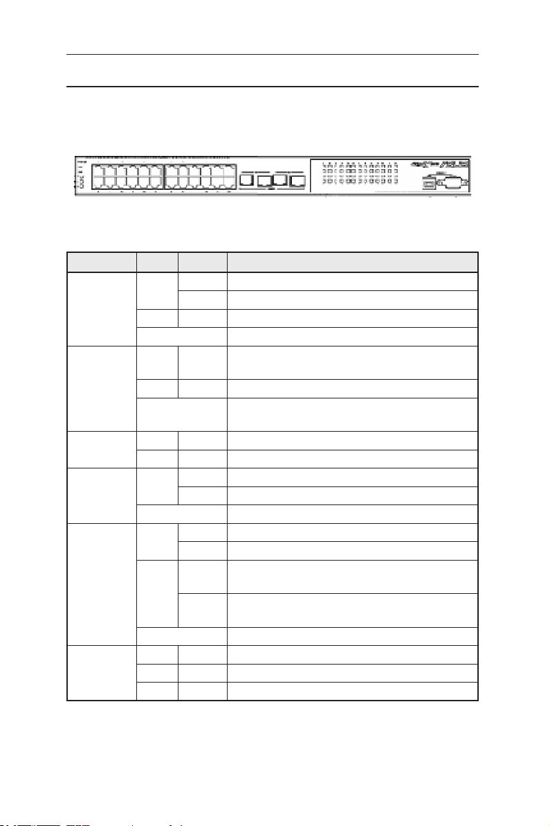
2.2 Front panel
The front panel includes 24 RJ-45 10/100Base-T ports, two 10/100/1000Base-T
ports, two SPF GBIC port and LED indicators that show the status of the system,
RPS, fan, and ports.
Figure 2. Front panel
Table 1. Front panel labels and LEDs
Label Color Status Description
SYSTEM Green ON Unit is powered on
Flashing Self-test, initiating, or downloading
Amber ON Abnormal temperature or voltage
OFF No power
RPS Green ON The Power Supply Unit (PSU) is working properly
and the switch has a good redundant power supply
Amber ON The PSU is abnormal and the switch is powered by RPS
OFF No power (system LED is also off); RPS does not work
properly or not installed (system LED is on)
FAN Green ON Both fans are working properly
Amber ON Both or either one of the fans stopped
10/100 ports Green ON Ethernet link is established
Flashing Data is being transmitted/received
OFF No Ethernet link
10/100/1000
port status
10/100/1000
port speed
Green ON Link (RJ-45 or SFP) is present; port is enabled
Flashing Data is being transmitted/received
Amber ON Link is present, but port is disabled either manually or
by spanning tree
Flashing Port is in one of the STP blocking, listening and
learning state
OFF No Ethernet link
Green ON 1000Mbps
Amber ON 100Mbps
OFF 10Mbps
4
Page 17
GigaX2024B L2 Managed Switch User Manual
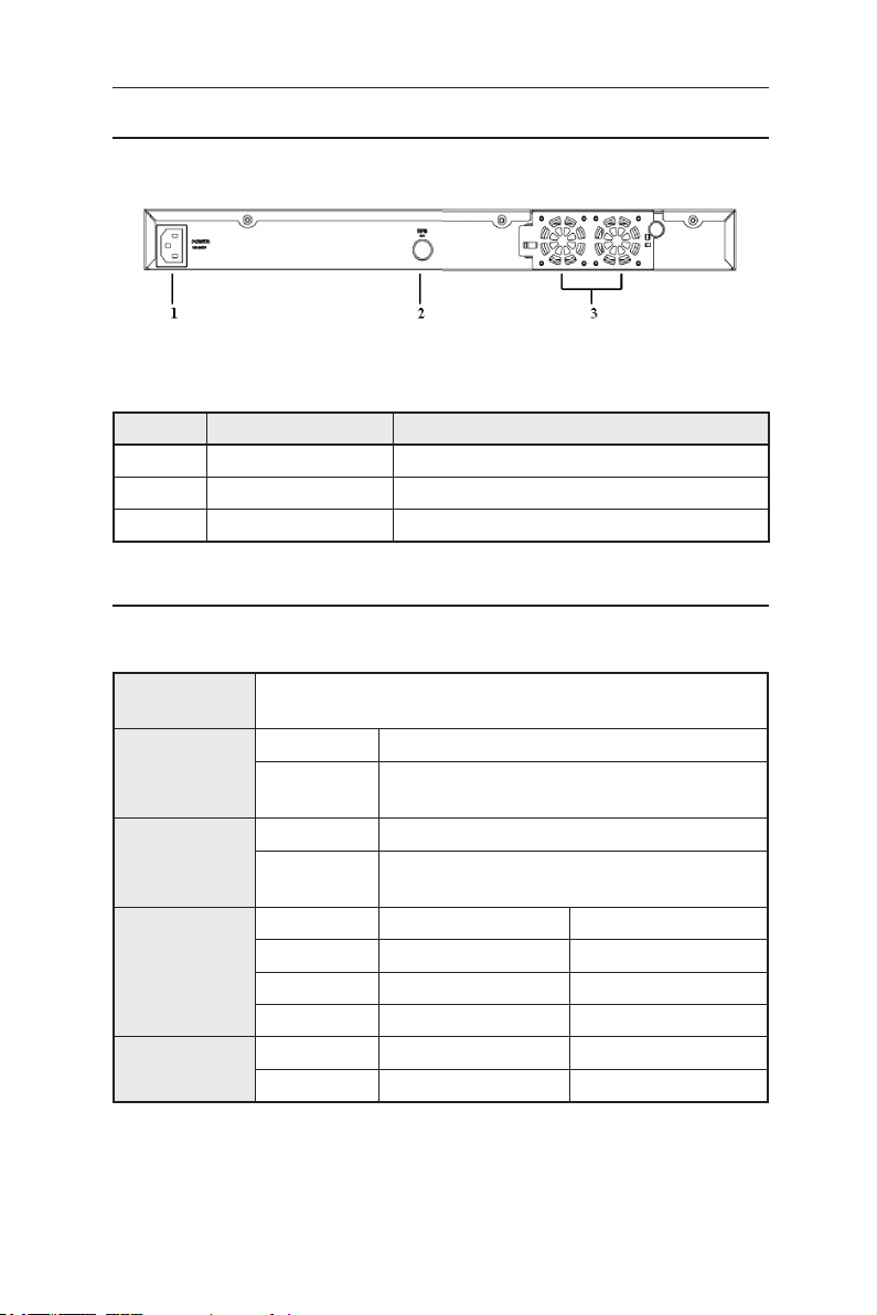
2.3 Rear panel
The switch rear panel contains the fan modules, a power connector and one RPS port.
Figure 3. Rear panel
Table 2. Rear panel labels
No. Item Description
1 Power Connector Connects to the supplied power cord
2 FAN1-FAN2 Replaceable system fans
3 RPS Redundant Power Supply connector
2.4 Technical specifications
Table 3. Technical specifications
Physical
Dimensions
Power
Redundant
Power Supply
(RPS)
Environmental
Ranges
Replaceable
Fans
43.5mm(H) x 444 mm(W) x 322mm(D)
Input Consumption
100-240V AC/
2.5A 50-60Hz
Input Output
100-240V AC/
1.8A 50-60Hz
Temperature 0 to 40°C (32 to 122°F) -25 to 70°C (-40 to 158°F)
Humidity 15 to 90% 0 to 95%
Altitude up to 10,000ft (3,000m) up to 40,000 ft (12,000m)
Dimensions Voltage and Current Speed
40 x 40 x 20 mm 12VDC, 0.13A 8200RPM
< 50 watts
12V DC/12.5A
Operating Storage
5
Page 18

GigaX2024B L2 Managed Switch User Manual
3 Quick start guide
This section provides the basic instructions to set up the switch environment.
Refer also to the GigaX2024B Installation Guide.
Part 1 shows how to install the GigaX2024B on a flat surface or on a rack.
Part 2 provides instructions to set up the hardware.
Part 3 shows how to configure basic settings on the GigaX2024B switch.
Before start, obtain the following information from your network administrator:
IP address for the switch
Default gateway for the network
Network mask for this network
3.1 Part 1 — Installing the hardware
3.1.1 Installing the switch on a flat surface
The switch must be installed on a level surface that can support the weight of
the switch and its accessories. Attach four rubber pads on the marked location
on the bottom of the switch.
3.1.2 Mounting the switch on a rack
1. Position the bracket posts with the holes on both sides of the switch.
2. Use three screws to secure the bracket to the switch.
3. Repeat the above steps for the other side of the switch.
4. Use four rack-mount screws to mount the switch to the rack (The rack-mount
screws are not provided in the package).
3.2 Part 2 — Setting up the switch
3.2.1 Connect the console port
For console management, use an RS232 (DB9) or a USB cable (requiring
installation of the USB driver included in the support CD) to connect the switch.
If you want to use Web interface, connect your PC to the switch using an
Ethernet cable.
6
Page 19
GigaX2024B L2 Managed Switch User Manual
3.2.2 Connect to the computers or a LAN
You can use Ethernet cable to connect computers, hubs and other switches to
the switch ports. Either crossover or straight-through Ethernet cable can apply
for connecting these devices.
Use a twisted-pair Category 5 Ethernet cable to connect the
1000BASE-T port. Otherwise, the link speed can not reach
1Gbps.
3.2.3 Attach the RPS module
Connect your Redundant Power Supply (RPS) module (optional) to the RPS jack on
the rear panel of the switch and make sure the other end of the RPS is connected to
the power cord. Connect to the power cord to a grounded power outlet.
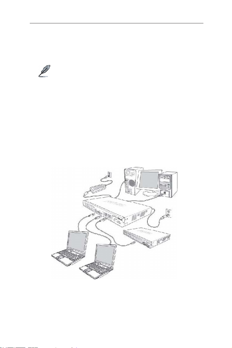
3.2.4 Attach the power adapter
1. Connect the AC power cord to the POWER receptacle on the back of the switch
and plug the other end of the power cord into a wall outlet or a power strip.
2. Check the front LED indicators with the description in Table 4. If the LEDs
light up as described, the switch hardware is working properly.
Figure 4. Overview of Hardware Connections
7
Page 20

GigaX2024B L2 Managed Switch User Manual
Table 4. LED Indicators
No. LED Description
1 System Solid green indicates that the switch is turned on. If this
light is off, check if the power adapter if attached to the
switch and plugged into a power source.
2 Switch ports
[1] to [26]
3 RPS Solid green indicates that an RPS module is successfully
4 Fan Solid green indicates that all fans are working properly
Solid green indicates that the connection between the
switch and other devices is built. Flashing means the
switch is transmitting data .
installed.
3.3 Part 3 — Basic switch setting for management
After completing the hardware connections, configure the basic settings for your
switch. You can manage the switch using the following methods:
•
Web interface:
management via Java®-enabled IE5.0 or higher version.
•
Command Line Interface:
3.3.1 Setting up through the console port
1. Use the supplied crossover RS-232 cable to connect to the console port on
the back of the switch. This port is a male DB-9 connector, implemented as a
data terminal equipment (DTE) connection. Tighten the retaining screws on
the cable to secure it on the connector. Connect the other end of the cable to
a PC running terminal emulation software. e.g Hyper Terminal.
2. Use the supplied USB cable to connect to a PC. You have to install the USB
driver from the switch CD-ROM before connection. The USB driver simulates
an additional COM port under Windows Me/2K/XP OS.
3. Make sure the settings of your terminal emulation software as follows:
a) Choose the appropriate serial port number
b) Set the data baud rate to 9600
c) Set the data format to no parity, 8 data bits and 1 stop bit
d) No flow control
e) Set VT1000 for emulation mode
4. After setting up the terminal, you can see the prompt “(ASUS)%” on the
terminal.
the switch features a set of web pages which enable easy
using console port to configure the switch.
8
Page 21

5. Type “login” to access the command line interface. The default user name is
“admin”. Skip the password by pressing
GigaX2024B L2 Managed Switch User Manual
<Enter>
.
You can change the password at any time through CLI (see
section 5.3.1). To protect your switch from unauthorized access,
you must change the default password as soon as possible.
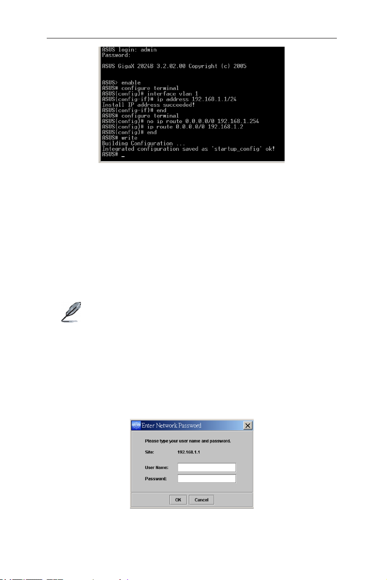
6. Follow these steps to assign an IP address to the switch:
Follow these steps to assign an IP address to the switch:
a) Type “enable”.
b) Type “configure terminal”, new prompt is “ASUS(config)#”.
c) Type “interface vlan 1”, the prompt is “ASUS (config-if)#”.
d) Type “ip address <your ip address> <your network mask>”. For example, if
your switch IP is 192.168.1.1 and the network mask is 255.255.255.0. Then
you should type “ip address 192.168.1.1/24”.
e) Type “end”, it will return to previous level with prompt “ASUS#”.
f) Type “write”, the changes will be applied and written to configuration file.
g) Type “reboot”.
If the switch has to be managed across networks, then a default gateway
or a static route entry is required. Follow these steps to assign a default
gateway or static route entry to the switch:
a) Entering “ASUS#”.
b) Type “ show run ning -con figu rati on” to vie w cur rent con figu rati on. If
incorrect route entry has been set, you should type “no ip route 0.0.0.0/0
192.168.1.254” to remove it.
c) Type “configure terminal”, new prompt is “ASUS(config)#”.
d) Type “no ip route 0.0.0.0/0 192.168.1.254” to clear default route.
e) Type “ip route 0.0.0.0/0 192.168.1.2” to set your default route.
f) Type “end”
g) Type “write”.
9
Page 22
GigaX2024B L2 Managed Switch User Manual
Figure 5. Console setup
3.3.2 Setting up through the Web interface
To connect your PC to the switch, your PC must have a valid IP in your network.
Contact your network administrator to obtain a valid IP for the switch. If you wish
to change the default IP address of the switch, follow section 3.3.1 to change the
IP address.
1. If Java Runtime Environment is not installed on your PC, Your PC will
automatically download and installs it. It means that your PC should be able
to reach the web site. If the Internet is not available, you should prepare it on
diskette and install it.
Java Runtime Environment is necessary to install on you PC
to access Web configuration manager. You can install it from
support CD packed with the main device.
2. At any PC connected to the network that the switch can access, open your
Web browser (Internet Explorer), and type the following URL in the address/
location box, and press
This is the factory default IP address of the switch.
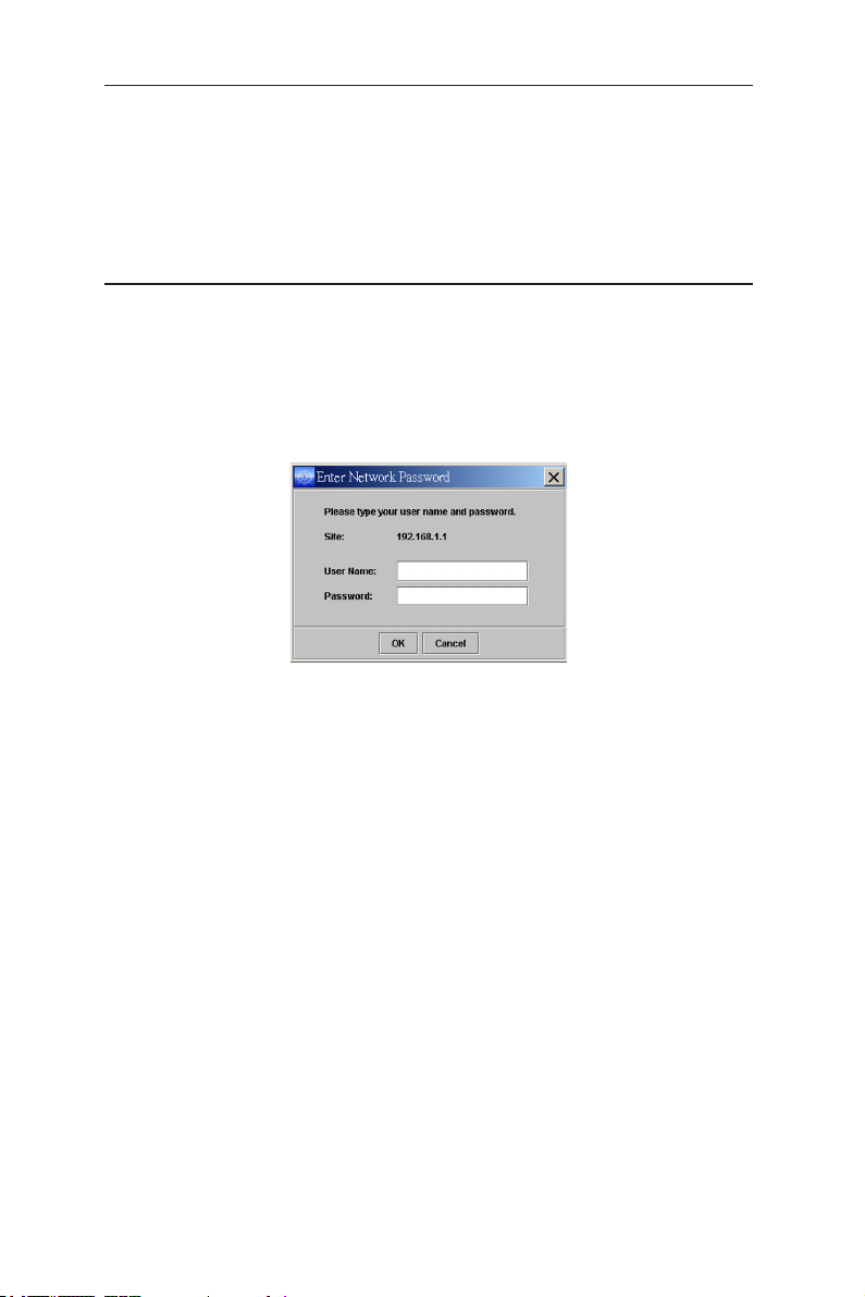
A login screen appears, as shown in Figure 6.
<Enter>
:
http://192.168.1.1
10
Figure 6. Login
Page 23
Enter your user name and password, and then click OK to enter the configuration
Manager. Use the following defaults the first time you log into this interface:
Default User Name: admin
Default Password: (no password)
GigaX2024B L2 Managed Switch User Manual
You can change the password at any time (see section 6.3.1
System Commands.
The browser will download java applet from the switch and this
will take several seconds.
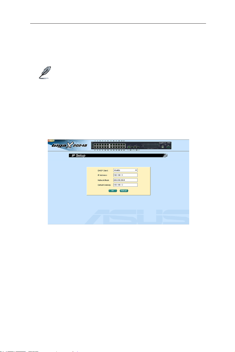
3. To setup a new IP address, click
address, network mask and default gateway, then click OK.
4. When the new address is applied to the switch, the browser can no longer
update the switch status window or retrieve any page. You need to retype
the new IP address in the address/location box, and press
Web link returns.
System
, then
IP Setup
<Enter>
. Fill in the IP
, then the
Figure 7. IP setup
11
Page 24
GigaX2024B L2 Managed Switch User Manual
4 Management with the Web Interface
The switch provides Web pages that allow switch management through the
Internet. The program is designed to work best with Microsoft Internet Explorer®
6.0, or later versions with Java® enabled.
4.1 Log into Web user interface
1. Open the web browser (IE) on your computer, type the following in the web
address (or location) box, and press
http://192.168.1.1
This is the factory default IP address for the switch. A login screen displays as
shown in Figure 8.
Figure 8. Configuration manager login screen
2. Enter your user name and password, then click OK.
Use the following defaults the first time you log into the system. You can
change the password at any time through CLI interface (see section 6.3.1 on
page 57).
Default User Name: admin
Default Password: <no password>
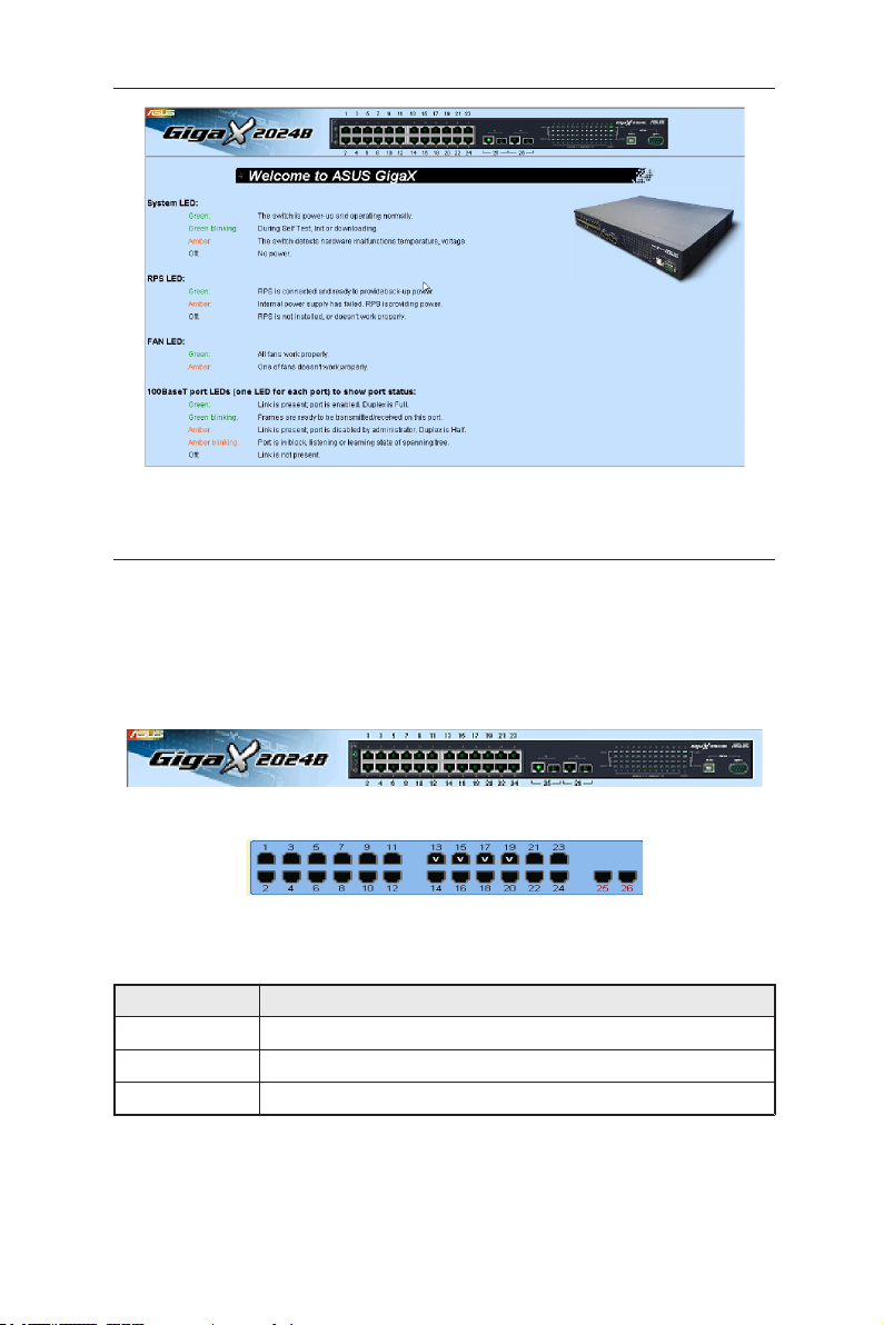
The home page appears each time you log into the program. See Figures 11
and 12).
<Enter>
:
12
Page 25
GigaX2024B L2 Managed Switch User Manual
Figure 9. Home page
4.2 Functional layout
The web-based configuration page consists of three separate frames. The top
frame has a switch logo and front panel as shown in Figures 13 and 14. This
frame remains on the top of the browser window all the times and updates the
LED status periodically. See Table 4 for the LED definitions. See Table 5 for the
color status description.
Figure 10. Top frame
Figure 11. Port selection panel
Table 5. Port color description
Port Color Description
Green Ethernet link is established
Amber Link is present but port is disabled manually or by spanning tree
OFF
Clicking on the port icon of the switch displays the port configuration in the lower
right frame.
No Ethernet link
13
Page 26
GigaX2024B L2 Managed Switch User Manual
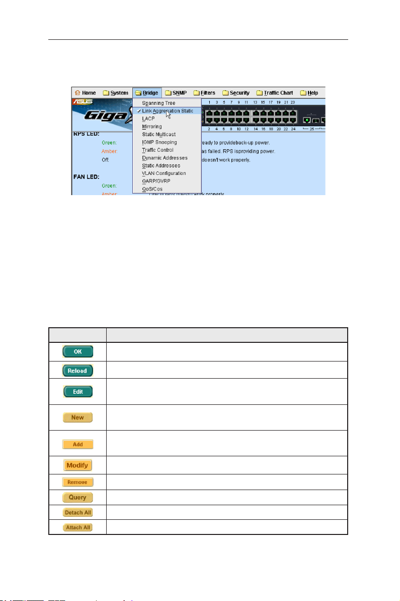
The menu items, as shown in Figure 12, contains all the features available for
switch configuration. These features are grouped into categories, e.g. System,
Bridge. You can click on any of these to display a specific configuration page.
Figure 12. Menu items
4.2.1 Menu navigation tips
To open a specifc configuration page, click on the desired menu item.
4.2.2 Commonly used buttons and icons
The following table describes the function for each button and icon used in the
application.
Table 6. Commonly used buttons and icons
Button/Icon Description
14
Stores any changes you have made on the current page.
Re-displays the current page with updated statistics or settings.
Modifies the existing configuration in the system, e.g. a static route or
a filter ACL rule and etc.
Adds the existing configuration to the system, e.g. a static MAC address
or a firewall ACL rule and etc.
Adds the existing configuration to the system, e.g. a static MAC address
or a firewall ACL rule and etc.
Modifies an existing entry
Deletes the selected item, e.g. a static route or a filter ACL rule and etc.
Find status of a certain item
Detach the feature from all ports on selcetion panel
Attach the feature from all ports on selcetion panel
Page 27
GigaX2024B L2 Managed Switch User Manual
4.3 System pages
System pages include management, IP setup, administration, reboot, and
firmware update function.
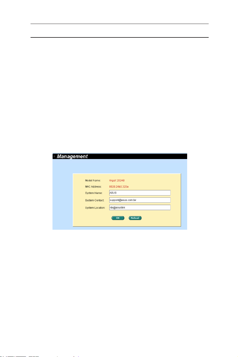
4.3.1 Management
The Management page contains the following information:
Model Name:
MAC Address:
System Name:
System Contact
System Location
Click on OK to make the setting effective immediately. Click on
refresh the setting to current value, as shown in Figure 13.
product name
switch MAC address
user assigned name to identify the system (editable).
(editable).
(editable).
Reload
to
Figure 13. Management
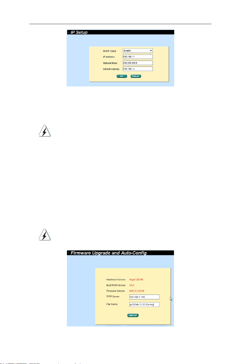
4.3.2 IP setup
The IP Setup page contains the following editable information:
DHCP Client:
IP Address:
Network Mask
Default Gateway
To save the changes and make them effective immediately, click OK. Use
to refresh the settings to current value.
Reload
Enables or disables DHCP.
Assigns a static IP address to the switch.
15
Page 28
GigaX2024B L2 Managed Switch User Manual
Figure 14. IP Setup
4.3.3 Reboot
The Reboot page contains a
Rebooting the system stops the network traffic and terminates
the Web interface connection.
button. Clicking the button to reboot the system.
Reboot
4.3.5 Firmware upgrade
The Firmware Upgrade and Auto-config page contains the following information:
Hardware Version:
Boot ROM Version:
Firmware Version:
number renews automatically after firmware update is complete.
Enter the TFTP server IP address and firmware name. Click
the switch firmware. See Figure 15 for reference.
For example: TFTP Server: 192.168.1.155 File name: gx2024b-3.2.02.0a.img
Click the upload button to load the assigned firmware to the
switch. Reboot the switch when upgrade completes. You need to
login again to the web interface.
shows the hardware revision number.
shows the version of the boot code
shows the current running firmware version. This
Upgrade
to update
Figure 15. Firmware Upgrade
16
Page 29
GigaX2024B L2 Managed Switch User Manual
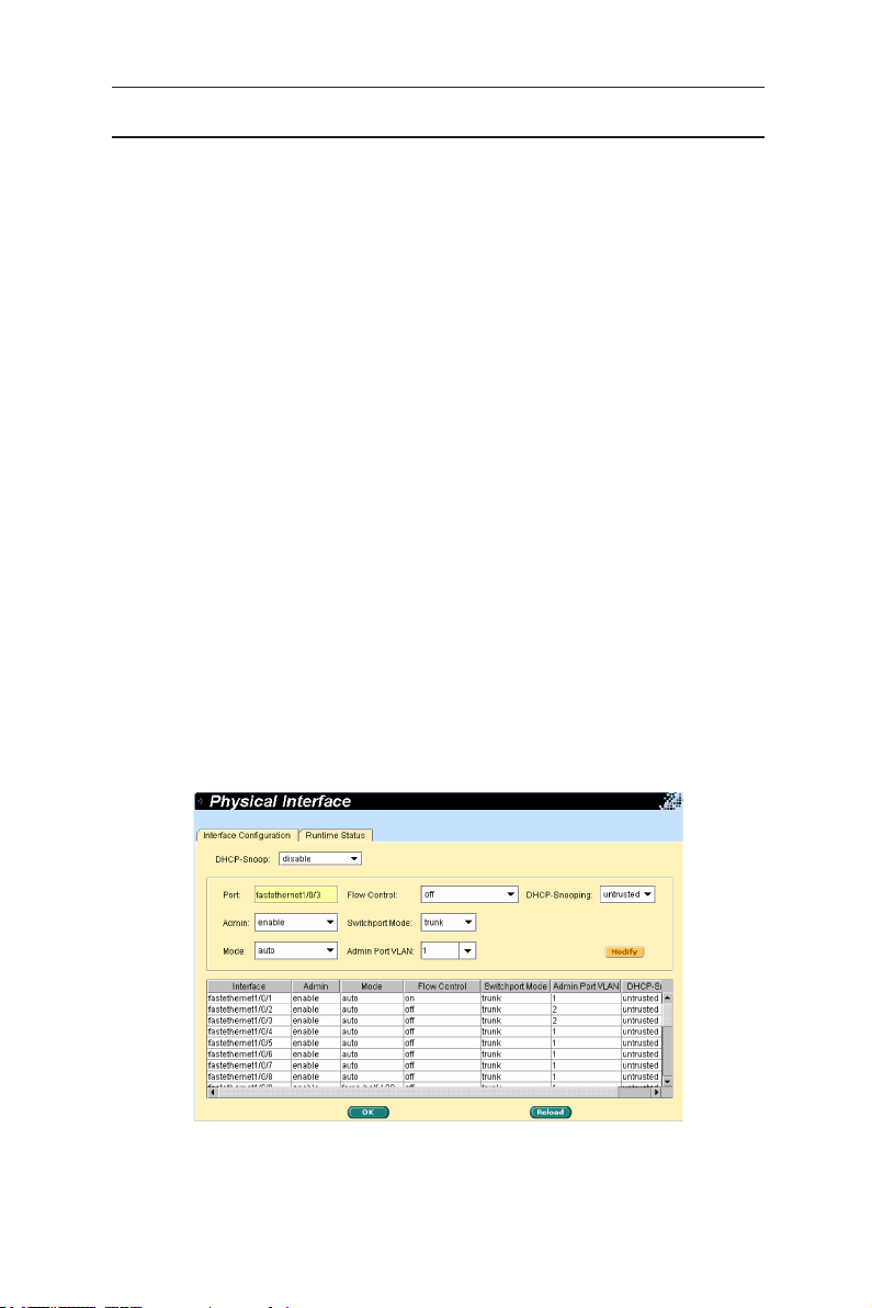
4.4 Physical interface
The Physical Interface shows the realtime Ethernet port status. You can configure
the port in following fields:
selects the port to configure
Port:
enables/disables the port
Admin:
set sthe speed and duplex mode
Mode:
Flow Control:
Switchport Mode:
Admin port VLAN:
DHCP-Snoop:
DHCP-Snooping:
Select the corresponding port number and configure the port setting, then
click on the
display window. However, the new settings do not take effect until the “Save
Configuration” is executed.
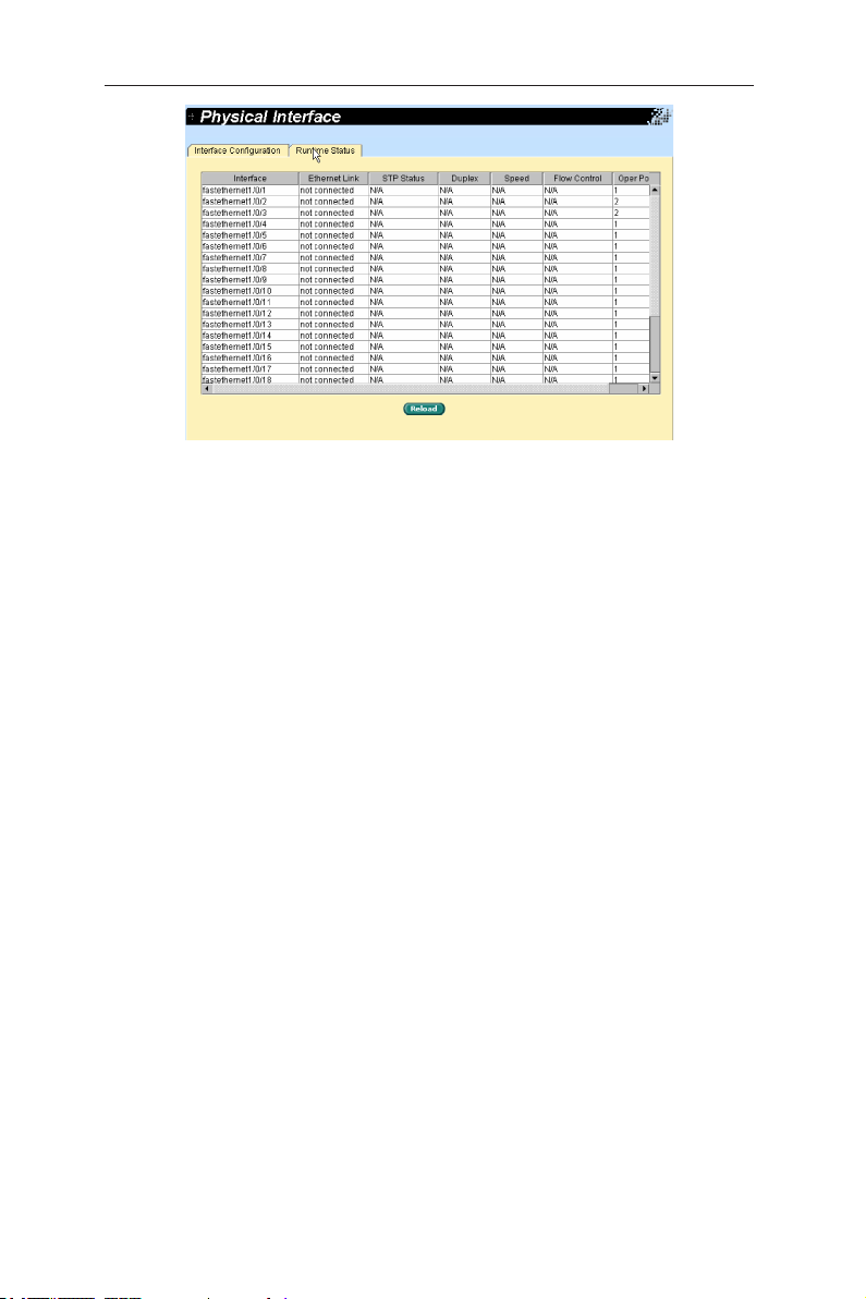
Runtime Status Window:
Ethernet Link:
STP Status:
Duplex:
Speed:
Flow Control:
mechanism.
enables/disables 802.3x flow control mechanism
sets port to trunk mode or access mode
assign the selected port to specific PVID
enable/disable DHCP snooping function
assign the selected port to be untrusted or trusted port
button. The field you change will update the content of the
Modify
displays the following information for each port
the link is connected or not connected.
the STP status
the duplex mode
link speed
the setting value to enable or disable 802.3x flow control
Figure 16. Physical interface - configuration
17
Page 30
GigaX2024B L2 Managed Switch User Manual
Figure 17. Physical interface - runtime status
18
Page 31

GigaX2024B L2 Managed Switch User Manual
4.5 Bridge
The Bridge page group contains layer 2 configurations, like link aggregation, STP.
4.5.1 Spanning tree
The page configures three types of Spanning Tree Protocol.
4.5.1.1 STP status
The first page “STP Status” can disable or enable STP. There are three modes
STP, RSTP and MSTP can be enabled. If MSTP is enabled, the following four
attributes are enabled at the same time:
Region Name:
Revision:
Instance ID:
map multiple VLANs into a single STP instance.
VLAN Group:
given instance
An alphanumeric configuration name
A configuration revision number
A STP instance, you can configure MSTP on your switch to
A group associates each of the potential 4094 VLANs to the
Figure 18. Spanning Tree- status
19
Page 32

GigaX2024B L2 Managed Switch User Manual
4.5.1.2 Current roots
It shows the information of current root bridge which include
• Instance ID
• The VLAN group belong to which instance ID
• MAC Address of root bridge
• Priority of root bridge
• Maximum age of root bridge
• Hello timer of root bridge
• Forwarding delay timer of root bridge
• Path cost of root bridge
• Root port of the bridge
20
Figure 19. Spanning tree - current roots
Page 33

GigaX2024B L2 Managed Switch User Manual
4.5.1.3 Bridge parameters
The spanning-tree parameters of BPDU transmission can be configured on this
panel:
Hello Time:
Max Age:
Forward Delay:
Bridge Priority:
Transmission Limit:
M-record) with a cost of 0 and the transmission limit set to the maximum value.
the interval between the generation of configuration BPDU
a timeout value to be used by all Bridges in the LAN
a timeout value to be used by all bridges in the LAN
the switch priority in the LAN
The root switch of the instance always sends a BPDU (or
Figure 20. Spanning tree - bridge parameters
21
Page 34

GigaX2024B L2 Managed Switch User Manual
4.5.1.4 Port parameters
This page contains a display window to show the current configuration for each
port. You can select a port then edit it. Click
for spanning-tree. The following fields are available:
Instance ID(MSTP Only):
MSTP on your switch to map multiple VLANs into a single STP instance.
Priority:
high priority. The port with lower priority is more likely to be blocked by STP
if a network loop is detected. The valid value is from 0 to 240.
Path Cost:
cost is more likely to be blocked by STP if a network loop is detected.
Link Type:
of the interface: a full-duplex port is considered to have a point-to-point
connection; a half-duplex port is considered to have a shared connection.
Edge Port:
should enable it only on ports that connect to a single end station.
Click OK to effect the settings. Click
sets the port priority in the switch. Low numeric value indicates a
the valid value is from 1 to 65535(RSTP:200000000). The higher
By default, the link type is determined from the duplex mode
An edge port is the same as a Port Fast-enabled port, and you
a spanning-tree instance, you can configure
to refresh the settings to current value.
Reload
to change the port setting
Modify
22
Figure 21. Spanning tree - port parameters
Page 35

GigaX2024B L2 Managed Switch User Manual
4.5.1.5 Runtime status
This page contains a display window to show the current status for each port.
Figure 22. Spanning tree - runtime status
4.5.2 Link aggregation static
The page configures the link aggregation static group (port trunking). The switch
provides maximum 32 link aggregation groups. This maximum can be achieved
on stacking configuration.
Port Selection Criterion:
ports of the link aggregation group according to source MAC address,
destination MAC address, source and destination MAC address, source IP
address, destination IP address, or source and destination IP address.
Trunk ID:
Port:
have to click on the icon to select the group members. The port can be
removed from the group by clicking the selected port again.
Click OK to make the setting send to the connected switch. Click
refresh the settings to current value. To make the configuration effective, go to
“Save Configuration” page, and click
You have to check the runtime link speed and duplex mode to make sure the
trunk is physically active. Go to Physical Interface and check the link mode in
the runtime status window for the trunk ports. If all the trunk members are in the
same speed and full duplex mode, then the trunk group is set up successfully.
If one of the members is not in the same speed or full duplex mode, the trunk
is not set correctly. Check the link partner and change the settings to have the
same speed and full duplex mode for all the members of your trunk group.
a number to identify the trunk group besides the group name
these port icons are listed the same way as on the front panel. You
the algorithm to distribute packets among the
to
Reload
.
Save
23
Page 36

GigaX2024B L2 Managed Switch User Manual
All the ports in the link aggregation group MUST operate in full
duplex mode at the same speed.
All the ports in the link aggregation group MUST be configured
in auto-negotiation mode or full duplex mode. This configuration
will make the full duplex link possible. If you set the ports in full
duplex force mode, then the link partner MUST have the same
setting. Otherwise the link aggregation could operate abnormally.
All the ports in the link aggregation group MUST have the same
VLAN setting.
All the ports in the link aggregation group are treated as a single
logical link. That is, if any member changes an attribute, the
others will change also. For example, a trunk group consists of
port 1 and 2. If the VLAN of port 1 changes, the VLAN of port 2
also changes with port 1.
24
Figure 23. Link aggregation
Page 37

GigaX2024B L2 Managed Switch User Manual
4.5.3 LACP
The page configures the LACP group (port trunking). The switch provides
maximum 32 link aggregation groups and up to 8 ports per group. This maximum
can be achieved on stacking configuration. For standalone GX3112 or GX3112F,
the maximum group is 6 since it supplies 12 ports only.The feature supplies five
statistics for verification.
Port Selection Criterion:
ports of the link aggregation group according to source MAC address,
destination MAC address, source and destination MAC address, source IP
address, destination IP address, or source and destination IP address.
Trunk ID:
Port:
have to click on the icon to select the group members. The port can be
removed from the group by clicking the selected port again.
a number to identify the trunk group besides the group name
these port icons are listed the same way as on the front panel. You
the algorithm to distribute packets among the
Figure 24. LACP
25
Page 38

GigaX2024B L2 Managed Switch User Manual
4.5.4 Mirroring
Mirroring, together with a network traffic analyzer, helps you monitor network
traffics. You can monitor the selected ports for egress or ingress packets.
Selects the mirror group. Each group consists of 24 Fast Ethernet
Mirror:
ports and one gigabit port. (for GigaX 2024B only)
Mirror Mode:
Monitor Port:
ports.
Click OK to make the setting send to the switch (HTTP server). Click
refresh the settings to current value.
Enables or disables the mirror function for the selected group.
Receives the copies of all the traffics in the selected mirrored
The monitor port can not belong to any link aggregation group.
The monitor port can not belong to any Private VLAN.
The monitor port can not operate as a normal switch port. It does
not switch packets or do address learning.
Reload
to
26
Figure 25. Mirroring page
Page 39

GigaX2024B L2 Managed Switch User Manual
4.5.5 Static multicast
This page can add multicast addresses into the multicast table. The switch
can hold up to 256 multicast entries. All the ports in the group will forward the
specified multicast packets to other ports in the group.
selects the port from selection panel. Or select an existing group
Port:
address from list panel to display
selects the VLAN group, it is VLAN-based feature
VLAN:
MAC Address:
assigns the priority for Class of Service
CoS:
Click OK to make the setting effective. Click
current value.
assigns the multicast address
Reload
to refresh the settings to
Figure 26. Static Multicast
27
Page 40

GigaX2024B L2 Managed Switch User Manual
4.5.6 IGMP snooping
IGMP snooping helps reduce the multicast traffics on the network by allowing
the IGMP snooping function to be turned on or off.
The first part provides the following settings,
Enable IGMP Snooping:
VLAN interfaces. By default, IGMP snooping is globally enabled on the
switch. When globally enabled or disabled, it is also enabled or disabled in
all existing VLAN interfaces.
If global snooping is disabled, you cannot enable VLAN snooping. If global
snooping is enabled, you can enable or disable VLAN snooping.
Last Member Query Interval:
receives an IGMP leave message from a subscriber on a receiver port, it
sends out an IGMP query on that port and waits for IGMP group membership
reports. If no reports are received in a configured time period, the receiver
port is removed from multicast group membership.
The second part provides the following settings,
If global snooping is enabled, you can enable or disable VLAN
Status:
snooping.
Immediate leave:
switch immediately removes a port when it detects an IGMP version 2 leave
message on that port. You should use the Immediate-Leave feature only
when there is a single host present on every port in the VLAN. Immediate
Leave is supported with only IGMP version 2 hosts.
However, if the static entries occupy all 256 spaces, the IGMP snoop does not
work normally. The switch only allows 256-layer 2 multicast groups.
When you enable IGMP Immediate-Leave processing, the
Globally enable IGMP snooping in all existing
Without Immediate Leave, when the switch
28
Figure 27. IGMP Snooping
Page 41

GigaX2024B L2 Managed Switch User Manual
4.5.7 Traffic control
Traffic control prevents the switch bandwidth from flooding packets including
broadcast packets, multicast packets and the unicast packets because of destination
address lookup failure. The limit number is a threshold to limit the total number of the
checked type packets. For example, if broadcast and multicast are enabled, the total
traffic amount for those two types will not exceed the limit value.
Selects an interface and assigns desirable settings, then click
Click OK to save the new configuration. To make the configuration effective, go to
“Save Configuration” page, then click
Reload
.
Modify
.
Figure 28. Traffic Control
4.5.8 Dynamic addresses
This page displays the result of dynamic MAC address lookup by port, VLAN ID, or
specified MAC address. The dynamic address is the MAC address learned by switch,
it will age out from the address table if the address is not learned again during the
age time. User can set the age time by entering a valid number from 10 to 1,000,000
in seconds. Then click on OK to save the new age value. To make the configuration
effective, please go to “Save Configuration” page, then click on
You can look up MAC addresses by checking the port, VLAN ID, or/and MAC address,
then click on the
. The address window will display the result of the query.
Query
Reload
.
Figure 30. Dynamic Address
29
Page 42

GigaX2024B L2 Managed Switch User Manual
4.5.9 Static addresses
You can add a MAC address into the switch address table. The MAC address
added by this way will not age out from the address table. We call it static
address. The switch only allows 1024 static addresses.
MAC Address:
VLAN ID:
Port Selection:
Click on the
information. Then you will see the new added entry shows in the address
window. You can remove the existed address by selecting the entry with the
mouse, then clicking on
address entries. You can look up a static address entry by MAC address and
VLAN ID, then click on the
switch (HTTP server). Click
make the configuration effective, please go to
click
Save
.
enter the MAC address
enter the VLAN ID that the MAC belongs
select the port which the MAC belongs
when you create a new static MAC address by the above
Add
Remove
Query
Reload
. The
. Click OK to make the setting send to the
to refresh the settings to current value. To
button updates the existed MAC
Modify
Save Configuration
page, then
30
Figure 30.Static Address
Page 43

GigaX2024B L2 Managed Switch User Manual
4.5.10 VLAN configuration
You can set up to 254 VLAN groups and show VLAN group in this page. VLAN1
is a default VLAN, which is created by system. It cannot be removed at all. This
feature prevents the switch from malfunctions. You can remove any existed
VLAN except the VLAN1.
You can assign the port to be a tagged port or an untagged port by toggling the
port button. There are three types of button in port selection panel:
“U” type:
packets.
“T” type:
“blank” type:
If one untagged port belongs to two or more VLAN groups at the same time, it
will confuse the switch and cause flooding traffics. To prevent it, the switch only
allows one untagged port belongs to one VLAN at the same time.
If you want to assign an untagged port from one VLAN to another, you have to
remove it from the original VLAN, or change it to be tagged in the original VLAN first.
VLAN ID:
created
Name:
DHCP-Snooping:
Click OK to save the configuration. To make the configuration effective, go to the
“Save Configuration” page, then click
untagged port that will remove VLAN tags from the transmitted
All packets transmitted from this port will be tagged.
This port is not a member of the VLAN group.
this field requires user to enter the VLAN ID when a new VLAN is
this field requires user to assign a name for the VLAN
enable/disable DHCP-Snooping function for the VLAN
.
Save
Figure 31. Tagged VLAN
31
Page 44

GigaX2024B L2 Managed Switch User Manual
4.5.11 GVRP
Generic Attribute Registration Protocol (GARP) VLAN Registration Protocol
(GVRP) is an application defined in the IEEE 802.1Q standard that allows for the
control of VLANs.
GVRP will run only on 802.1Q trunk ports and is used primarily to prune traffic
from VLANs that does not need to be passed between trunking switches. There
are some parameters to configure GVRP:
GVRP Enable:
enable GVRP on the switch before you can configure the 802.1Q ports for
GVRP operation.
Port Mode:
GVRP must be configured on both sides of the trunk to work correctly.
Registration:
ports use GVRP join messages from neighboring switches to prune the
VLANs running across the 802.1Q trunk link. If the device on the other side
is not capable of sending GVRP messages, or if you do not want to allow the
switch to prune any of the VLANs, use the fixed mode. Fixed mode ports will
forward for all VLANs that exist in the switch database. Ports in forbidden
mode forward only for VLAN 1.
By default GVRP is not enabled for the switch. You must first
enables/disables GVRP on the individual 802.1Q trunk port.
By default GVRP ports are in normal registration mode. These
Edit the following attributes as needed:
Joint Timer:
Leave Timer:
LeaveAll Timer:
32
Set value in centiseconds.
Set value in centiseconds.
Set value in centiseconds.
Figure 32. GVRP
Page 45

GigaX2024B L2 Managed Switch User Manual
Figure 33. GARP timer
4.5.12 QoS and CoS
4.5.12.1 802.1p priority
Eight egress queues on all switch ports. These queues can either be configured
with the Weighted Round Robin (WRR) scheduling algorithm or configured with
one queue as a strict priority queue and the other queues for WRR. The strict
priority queue must be empty before the other queues are serviced. You can use
the strict priority queue for mission-critical and time-sensitive traffic. There are
three options:
First Come First Service:
High Priority First:
Weighted Round Robin (WRR):
the ratio of the weights is the ratio of frequency in which the WRR scheduler
de-queues packets from each queue.
Click OK to save the configuration. To make the configuration effective, go to
“Save Configuration” page, and click
the first come frame has the highest priority
Packetʼs priority depends on its CoS value
If WRR scheduling algorithm is enabled,
.
Save
33
Page 46

GigaX2024B L2 Managed Switch User Manual
Figure 34. 802.1p Priority
4.5.12.2 CoS queue mapping
The switch supports four egress queues for each port with a strict priority
scheduler. That is, each CoS value can map into one of the four queues. For
strict priority, the queue four has the highest priority to transmit the packets.
Click OK to save the configuration. To make the configuration effective, go to
“Save Configuration” page, and click
The CoS values range from 0 for low priority to 4 for high priority.
Save
.
34
Figure 35. CoS Queue Mapping
Page 47

GigaX2024B L2 Managed Switch User Manual
4.5.12.3 QoS bandwidth
Some VLAN tag related field settings for each port are included in this page. It
includes:
Select a port from list window to configure
Port:
Ingress Bandwidth:
Default CoS:
to this CoS value in the VLAN tagged
Click on
to save the configuration. To make the configuration effective, go to “Save
Configuration” page, and click
Modify
Maximum ingress bandwidth for selected port
every untagged packet received from this port will be assigned
to change the content in the port list window. Click on OK
.
Save
Figure 36. QoS Bandwidth
35
Page 48

GigaX2024B L2 Managed Switch User Manual
4.6 SNMP
This group offers the SNMP configuration including Community Table, Host
Table, and Trap Setting
4.6.1 Community table
You can type different community names and specify whether the community
has the privilege to do set action (write access) by checking the box. Click OK to
save the configuration permanently or
to refresh the page.
Reload
36
Figure 37. Community table
Page 49

GigaX2024B L2 Managed Switch User Manual
4.6.2 Host table
This page links host IP address to the community name that is entered in
Community Table page. Type an IP address and select the community name
from the drop-down list. Click OK to save the configuration permanently or
to refresh the page.
Reload
Figure 38. Host table
4.6.3 Trap setting
By setting trap destination IP addresses and community names, you can enable
SNMP trap function to send trap packets in different versions (v1 or v2c). Click
to save the configuration permanently or to refresh the page.
Figure 34. Trap setting
37
Page 50

GigaX2024B L2 Managed Switch User Manual
4.6.4 SNMPv3 VGU table
Thereʼre two articles presenting the new security features defined by SNMPv3.
The User-based Se cur ity Model (US M), which pro vid es authenti cat ion ,
encryption, and decryption of SNMPv3 packets. The View-based Access Control
Model (VACM), which provides access control. The followings are three related
pages. Click to save the configuration permanently or to refresh the page.
4.6.4.1 VACM view
VACM View is used to view the information of SNMPV3 VACM Group.
View Name:
View Type:
when View Subtree matches the Oid in the SNMPv3 message.
View Subtree:
the Oid to match the Oid in the SNMPv3 message. The match is good when
the subtree is shorter than the Oid in the SNMPv3 message.
Click on the
information. Then you will see the new added entry shows in the view window.
You can remove the existed views by selecting the entry with the mouse, then
clicking on
Click OK to save effective. Click
To make the configuration effective, please go to “Save Configuration” page,
then click on
enter the security group name.
enter the View Type that the View belongs. Included or Excluded
enter the View Subtree that the View belongs. The Subtree is
when you create a new VACM View entry by the above
Add
Remove
Save
. The
.
button updates the existed VACM View entries.
Modify
to refresh the settings to current value.
Reload
38
Figure 40. SNMPv3 VGU Table 1
Page 51

GigaX2024B L2 Managed Switch User Manual
4.6.4.2 VACM group
VACM Group is used to configure the information of SNMPV3 VACM Group.
Group Name:
Read View Name:
related SNMP messages are Get,GetNext,GetBulk.
Write View Name:
related SNMP message is Set.
Notify View Name:
related SNMP messages are Trap,Report..
Security Model:
Any is suitable for v1,v2,v3. USM is SNMPv3 related.
Security level:
NoAuth, AuthNopriv, AuthPriv can be chosen..
Click on the
information. Then you will see the new added entry shows in the group window.
You can remove the existed group by selecting the entry with the mouse, then
clicking on
entries. Click OK to save effective. Click Reload to refresh the settings to current
value. To make the configuration effective, please go to “Save Configuration”
page, then click on
enter the security group name.
enter the Read View Name that the Group belongs. The
enter the Write View Name that the Group belongs. The
enter the Notify View Name that the Group belongs. The
enter the Security Model Name that the Group belongs.
enter the Security level Name that the Group belongs. Only
when you create a new VACM group entry by the above
Add
Remove
. The
Save
.
button updates the existed VACM Group
Modify
Figure 41. SNMPv3 VGU Table 2
39
Page 52

GigaX2024B L2 Managed Switch User Manual
4.6.4.3 USM user
USM User is used to configure the information of SNMPV3 USM User.
User Name:
Group Name:
Auth Protocol:
belong. Only NoAuth ,MD5, SHA1 can be chosen. If the NoAuth is chosen,
there is no need to enter password.
Auth Password:
password needs at least 8 characters or digits.
Priv Protocol:
belong. Only NoPriv ,DES can be chosen. If the NoPriv is chosen, there is
no need to enter password.
Priv Password:
password needs at least 8 characters or digits.
Security level:
NoAuth, AuthNopriv, AuthPriv can be chosen.
Click on the
information. Then you will see the new added entry shows in the group window.
You can remove the existed group by selecting the entry with the mouse, then
clicking on
entries. Click OK to save effective. Click Reload to refresh the settings to current
value. To make the configuration effective, please go to “Save Configuration”
page, then click on
User name of a specific security group
enter the security group name
enter the Auth Protocol that SNMP User and Security Group
enter the password that the Auth Protocol belongs. The
enter the Priv Protocol that SNMP User and Security Group
enter the password that the Priv Protocol belongs. The
enter the Security level Name that the Group belongs. Only
when you create a new VACM group entry by the above
Add
Remove
. The
Save
.
button updates the existed VACM Group
Modify
40
Figure 42. SNMPv3 VGU Table 3
Page 53

GigaX2024B L2 Managed Switch User Manual
4.7 Filter pages
The switch can filter certain traffic types according to packet header information
from Layer 2 to Layer 4. Each filter set includes a couple of rules. You have to
attach the filter set to certain ports to make the filter work.
4.7.1 Filter set
The switch defines two modes of rules, one is MAC mode and the other is IP
mode. Only the same mode of rules can bundle together to form a filter set.
Each mode has different fields to configure. For example, you can use IP mode
rule to filter FTP packets.
You can check the MAC Filter and give a Name then add it. You also can check
the IP Filter and give an ID/Name then clicking on
configuration permanently or
editing.
Click on a filter set to select the set you want to edit or remove. Second, click
on
have to follow the rules to make a valid filter set.
One set consists of a type of rules. The rules having the same fields to filter
packets belong to one type. For example, two rules filter packets with two
destination IP addresses, then they are the same type. But a rule filtering source
IP address does not belong to the same type.
Four types of rules can apply to ports at the same time. If there are more than
four types, the system automatically disables the rules.
to enter the rule page, or click on
Edit
to refresh the page. Please click OK before
Reload
Remove
. Click OK to save the
Add
to remove the filter set. You
Figure 43. Filter Set
41
Page 54

GigaX2024B L2 Managed Switch User Manual
The Filter Rule page provides options for rule modes, one is MAC rule and the
other is IP rule. If you did not enter the MAC address in the blank box, it means
the rule donʼt care the MAC value. In IP rule setup, you can enter any of the 5
types: source IP, destination IP, protocol, source application port and destination
application port. The
field determines if the packet should be dropped or
Action
forwarding when it matches the rule. If a packet matches two rules with different
action, the packet will follow the rule showed first in the rule list.
Figure 44. Filter rule in MAC mode
Figure 45. Filter rule in IP mode
Two examples tell us about the how of IP provisioning:
1. Assign a dedicated IP , Type = subnet, IP = 10.10.1.2, Wildcard = 0.0.0.0
2. Assign a subnet (a group of IP), Type = subnet, IP = 10.10.1.0, Wildcard =
0.0.0.255
42
Page 55

GigaX2024B L2 Managed Switch User Manual
4.7.2 Filter attach
A filter set is idle if you did not attach it to any ingress port. Use the Filter Attach
page to attach a filter set to ingress ports.
Click OK to save the configuration. To make the configuration effective, go to
the “Save Configuration” page, then click
page.
To attach a filter set to ports:
Attach to all ports:
Attach to certain ports:
Detach from all ports:
the filter set applies to all the ports of the system.
you can specify the ingress ports to be applied.
remove all the filters from the attached ports.
You may not detach certain ports after issuing an “Attach All”
command. If you wish to detach ports, use the “Detach All”
command.
Once the filter set is attached to the ingress ports, it will filter the packets
according to the ingress port and the packet fields in the rules. For example, a
set with a single rule to filter out destination MAC address 00:10:20:30:40:50
is attached to ingress port 3. A packet with destination MAC 00:10:20:30:40:50
from port 3 is not permitted.
Save
, or click on
Reload
to refresh the
Figure 46. Filter attach
43
Page 56

GigaX2024B L2 Managed Switch User Manual
4.8 Security
The switch supports the 802.1x port-based security feature. Only authorized
hosts are allowed to access the switch port. Traffic will be blocked from
unauthenticated host. Authentication can be provided via a RADIUS server or
the local database in the switch.
The switc h also suppor t s dyna m ic VALN ass i gnment throug h 802.1 x
authentication process. The VLAN information for the users/ports should be
configured in the authentication server properly before enabling this feature.
4.8.1 Port access control
Port Access Control is used to configure various 802.1x parameters. 802.1x
uses either RADIUS server or local database to authenticate port users.
The first part is the Bridge (Global) settings:
Sys-Auth-Control:
Authentication Method:
authenticate the port user.
The second part is the port settings. Please click
the modifications:
Specify which port to configure from port list window.
Port:
Multi-host:
to use the port if ONE of the hosts passed the authentication. If disabled,
only ONE host is allowed to use the port.
Authentication Control:
port is forced authorized. Thus, traffic from all hosts is allowed to pass.
Otherwise, if “ForceUnauthorized” is selected, the selected port is blocked
and no traffic can go through. If “Auto” is selected, the behavior of the
selected port is controlled by 802.1x protocol. All ports should be set to “Auto”
under normal conditions.
Reauthentication:
user again when the re-authentication time is up.
ReAuthentication Time:
period the switch uses to re-send authentication request to the port user (see
above).
Quiet Period:
before sending another authentication request to the port user.
Retransmission Time:
checks it to enable the authentication
RADIUS or Local database can be used to
when youʼre done with
Modify
If enabled, ALL hosts connected to the selected port are allowed
If “ForceAuthorized” is selected, the selected
Once enabled, the switch will try to authenticate the port
If “Reauthentication” is enabled, this is the time
If authentication failed, the switch waits upon this time period
If the port user failed to respond to authentication
44
Page 57

GigaX2024B L2 Managed Switch User Manual
request from the switch, the switch waits upon this time period before
sending another authentication request to the port user.
Max Reauthent Attempt:
Retry count if the port user failed to respond to
authentication requests from the switch.
Guest Vlan:
Click OK to make the settings permanent. Click
Specify a guest VLAN to clients that are not 802.1x-capable.
to refresh the settings to
Reload
current value.
Figure 47. Port Access Control
45
Page 58

GigaX2024B L2 Managed Switch User Manual
4.8.2 Dial-in user
Dial-in User is used to define users in the local database of the switch.
User Name:
Password:
Confirm Password:
Vlan ID:
Please click
modifications. Click
to make the settings permanent. Click
OK
current value.
New user name.
Password for the new user.
Enter the password again.
Specify the VLAN ID assigned to the 802.1x-authenticated clients.
to add the new user. Click
Add
Remove
when you want to remove the selected user. Click
when youʼre done with the
Modify
to refresh the settings to
Reload
46
Figure 48. Dial-In user
Page 59

GigaX2024B L2 Managed Switch User Manual
4.8.3 RADIUS
In order to use external RADIUS server, the following parameters are required to
be setup:
Authentication Server IP:
Authentication Server Port:
listening to.
Authentication Server Key:
GigaX and the RADIUS server.
Confirm Authentication Key:
The VLAN of the RADIUS server connected to the switch must
be the same as the VLAN of the system management interface.
Please click OK to make the settings permanent. Click
settings to current value.
The IP address of the RADIUS server.
The port number for the RADIUS server is
The key is used for communications between
Re-type the key entered above.
to refresh the
Reload
Figure 49. RADIUS
47
Page 60

GigaX2024B L2 Managed Switch User Manual
4.8.4 Port security
Th e swit ch als o sup p orts por t secu rity feat ure. It enab l es a sys t emʼs
administrator to control who can connect to their network. You can use the
port security feature to restrict input to an interface by limiting and identifying
MAC addressed of the stations allowed to access the port. When you assign
secure MAC addresses to a secure port, the port does not forward with source
addresses outside the group of defined addresses. This decreases the possibility
that a non-authorized device can use our network for malicious purposes.
4.8.4.1 Port configuration
The page is used to configure port security configuration.
First, you must select a port by clicking it from the following table. Then, begin
to set the port configuration. Please click
modifications:
a) Admin: Enable or disable port security feature.
b) Violation Mode: It decides the port behavior when security violation happens.
If “Shutdown” is selected, the port becomes blocking state and system
logs a syslog message, and increments the violation counter. If “Restrict” is
selected, a syslog message is logged, and the violation counter increments.
If “Protect” is selected, you are not notified that a security violation has
occurred.
c) Max MAC Address: The maximum numbers of secure MAC addresses on
this port. It is between 1 and 132 and the total number in the system is 1024.
d) Aging Time: The aging time for this port. After the expiration of the time, the
corresponding dynamic secure MAC address will be removed from secure
MAC address table. The valid range is 0 to 1440(mins). If the time is equal
to 0, the aging mechanism is disabled for this port.
e) Aging Type: The aging type determines the action when the secure MAC
addresses are aged out. If “Absolute” is selected, the secure addresses on
the port are deleted after the specified aging time. If “Inactivity” is selected,
the secure addresses in the port are deleted only if there is no data traffic
from the secure source MAC address for the specified time period.
Click OK to make the settings permanent. Click
current value.
when youʼre done with the
Modify
to refresh the settings to
Reload
48
Page 61

GigaX2024B L2 Managed Switch User Manual
Figure 50. Port security
4.8.4.2 Port status
This page shows the current port status, MAC address counts, static MAC
address counts, and violation count.
Port has five statuses:
a)
NoOper:
b)
SecureUp:
c)
SecureDown:
when port security is configured to be enabled but could not be enabled due
to certain reasons such as conflict with other features.
d)
Restrict:
violation mode is ʻrestrictʼ.
e)
Shutdown:
violation when the violation mode is ʻshutdownʼ.
When some port status is “Shutdown”, you can click it and select “Re-Start”
to “Yes”. It will restart the port and change status to “SecureUp”. Please click
Modify
Click OK to make the settings permanent. Click
current value.
This indicates port security on the port is configured to disabled.
This indicates port security is operational.
This indicates port security is not operational. This happens
This indicates that the port occurs port security violation when the
This indicates that the port is shutdown due to port security
when youʼre done with the modification.
to refresh the settings to
Reload
49
Page 62

GigaX2024B L2 Managed Switch User Manual
Figure 51. Port status
4.8.4.3 Secure MAC address
Secure MAC Address offers three functions for user management:
a)
b)
c)
You can select a port by “Port Selection” field. After click “Query”
Query:
button, it will show all MAC addresses on this port.
User can select some port by “Port Selection” field, and input a MAC
Add:
address to add on “MAC Address” field. After push “Add” button, the MAC
address will add on the selected port and the type of the MAC is static.
Remove:
some port. Selecting a MAC from list and pushing “Remove” button, it will be
removed immediately.
You can use “Query” function to display all the MAC addresses on
50
Figure 52. Secure MAC Address
Page 63

GigaX2024B L2 Managed Switch User Manual
4.9 Traffic chart
The Statistics Chart pages provide network flow in different charts. You can
specify the period time to refresh the chart. You can monitor the network traffic
amount in different graphic chart by these pages. Most MIB-II counters are
displayed in these charts.
Click Refresh Rate to set the period for retrieving new data from the switch.
You can differentiate the statistics or ports by selecting Color. Finally, click on
Draw to let the browser to draw the graphic chart. Each new Draw will reset the
statistics display.
4.9.1 Traffic comparison
This page shows the one statistics item for all the ports in one graphic chart.
Specify the statistics item to display and click the Draw, the browser will show
you the update data and refresh the graphic periodically.
Figure 53. Traffic comparison
51
Page 64

GigaX2024B L2 Managed Switch User Manual
4.9.2 Error group chart
Selecting the Port and display Color, then clicking the Draw, the statistics
window shows you all the discards or error counts for the specified port. The
data is updated periodically.
Figure 54. Error group chart
4.9.3 Historical status
You can display information for different ports and statistics items in this chart.
Since this shows the history of the statistics information, the line chart keeps the
old data even it is refreshed.
52
Figure 55. Historical status
Page 65

GigaX2024B L2 Managed Switch User Manual
4.10 Cable diagnosis
To analysis the cabling plant for the common cable problems, such as open
circuits, short circuits and impedance mismatches.
Figure 56. Cable diagnosis
4.11 Save configuration
To save configuration permanently, you have to click
takes effective after a successful save.
Sometimes you may want to reset the switch configuration, you can click on
Restore
reboot will follow this restoration process.
to reset the configuration file to factory default. Of course, a system
You will lose all the configurations when you choose to restore
the factory default configurations.
Figure 57. Save configuration
. The setting also
Save
53
Page 66

GigaX2024B L2 Managed Switch User Manual
5 Console interface
This chapter describes how to use console interface to configure the switch. The
switch provides RS232 and USB connectors to connect your PC. Use a terminal
emulator on your PC such as HyperTerminal and command line interpreter to
configure the switch. You have to set up the terminal emulator with baud rate
9600, 8 bit data, no parity, and 1 stop bit, and no flow control.
Once you enter CLI mode, type “?” will display all available command help
messages. This is very useful when you are not familiar with the CLI commands.
All the CLI commands are case sensitive.
5.1 Power-on self test
POST is executing during the system booting time. It tests system memory, LED
and hardware chips on the switchboard. It displays system information as the
result of system test and initialization. You can ignore the information until the
prompt, “ASUS>:” appears.
Figure 58. CLI interface
5.1.1 Boot ROM command mode
During the POST process, you can enter a “Boot ROM Command” mode by
pressing <ENTER> key. Enter the “?” key to show the help messages for all
available commands.
Although the commands are h elpful in some situation, we
STRONGLY suggest users not to use them if you donʼt know the
command function.
54
Page 67

GigaX2024B L2 Managed Switch User Manual
Figure 59. Boot ROM command mode
5.1.2 Boot ROM commands
The followings are two types of boot ROM commands,
• command: The current settings will be displayed.
• command with new setting: The current setting will be replaced by specified
new setting.
Command Parameters Usage Notes
baudrate Baud rate 9600, 38400,
57600, 115200
ethaddr none none get MAC address
gatewayip IP address xxx.xxx.xxx.xxx set gateway IP address
go none none boot firmware image
? or help none none print online help
ipaddr IP address xxx.xxx.xxx.xxx set TFTP client IP address
xload none none load binary file over serial line (X
netmask mask xxx.xxx.xxx.xxx set network mask
ping host xxx.xxx.xxx.xxx send ICMP echo_request to host
pwd none none reset switch password
serverip IP address xxx.xxx.xxx.xxx set TFTP server IP address
slot slot 1, 2, auto select boot slot
tftpboot filename xxx.img load image via network with TFTP
version none none print monitor version
You need to set up the terminal
emulatror with the same baut rate
modem)
55
Page 68

GigaX2024B L2 Managed Switch User Manual
5.2 Login and logout
To enter the CLI mode, you have to give a valid user name and password. As
the first time login, you can enter “
For security reason, please change the user name and password after login.
Once you forget the use name and password, you may contact ASUS support
team or restore the default user account in the
“pwd”. If you take the second choice, the default user “admin” will be restored.
Type “exit” to leave the CLI mode safely. This action allows you to secure the
CLI mode. The next user has to do login again with authorized user name and
password.
” as the user name (without password).
admin
Boot ROM
Command mode –
5.3 CLI commands
The switch provides CLI commands for all managed functions. This way, you
can follow the instructions and set up the switch correctly as easily as using
WEB interface to configure the switch.
Always use “?” or “list” to get the available commands list and help.
Always use “end” to get back to the root directory(enable mode).
5.3.1 User account
5.3.1.1 Add user
Add a new user or modify an existing userʼs password.
CLI Syntax:
Example:
add user user-name password
ASUS# user add admin 123
5.3.1.2 Delete user
Delete an existing user.
CLI Syntax:
Example:
delete user user-name
ASUS# user delete admin
5.3.2 Backup and Restore
5.3.2.1 Backup start-up configuration file
Backup the start-up configuration file “ startup_config” of the switch to TFTP server.
56
Page 69

CLI Syntax: copy startup-config tftp: URL
Example: ASUS# copy startup-config tftp: 192.168.8.56/gx2024b.cfg
GigaX2024B L2 Managed Switch User Manual
5.3.2.2 Restore start-up configuration file
Restore the start-up configuration file “ startup_config” of the switch from TFTP
server.
CLI Syntax: copy tftp: URL startup-config
Example: ASUS# copy tftp: 192.168.1.2/gx2024b.cfg startup-config
5.3.3 System management configuration
5.3.3.1 Firmware upgrade
Upgrading new firmware into switch.
CLI Syntax: archive download-sw /overwrite tftp: ImageFile
Example: ASUS# archive download-sw /overwrite
tftp: 192.168.1.3/GX2024B-3.2.02.00-release.img
5.3.3.2 configure terminal
Use the write configuration command on the switch to configuration.
CLI Syntax: configure terminal
Example: ASUS# configure terminal
5.3.3.3 enable
Entering enable mode and turn on privileged mode command.
CLI Syntax: enable
Example: ASUS# enable
5.3.3.4 disable
Turning off privileged mode and back to user mode.
CLI Syntax: disable
Example: ASUS# disable
57
Page 70

GigaX2024B L2 Managed Switch User Manual
5.3.3.5 end
This command let user end current mode and down to enable mode.
CLI Syntax: end
Example: ASUS# end
5.3.3.6 exit
This command let user exit current mode and down to previous mode.
CLI Syntax: exit
Example: ASUS# exit
5.3.3.7 help
This command lists all of the command of the operation mode.
CLI Syntax: list
Example: ASUS# list
Example: ASUS# ?
5.3.3.8 host name
Displays the given name of the switch. This is an RFC-1213 defined MIB object
in System Group, and provides administrative information on the managed node.
CLI Syntax: hostname WORD
Example: (config)# hostname Switch
If you put a name in the name description field, the switch system name changes
to the new one.
5.3.3.9 System contact
Displays the detail information of contact about the switch. This is an RFC-1213
defined MIB object in System Group, and provides contact information on the
managed node.
CLI Syntax: snmp-server contact DWORD
Example: (config)# snmp-server contact fae@loop.com.tw
If you put the contact description in the contact description field, the switch
contact will change to the new one.
58
Page 71

GigaX2024B L2 Managed Switch User Manual
5.3.3.10 System Location
Displays the physical location of the switch. This is an RFC-1213 defined MIB
object in System Group, and provides the location information on the managed
node.
CLI Syntax: snmp-server location DWORD
Example: (config)# snmp-server location Loop-Taipei
Type in the location description in the location description field to change the
location.
Figure 60. SYS commands
5.3.3.11 IP address and network mask
Displays the IP address for the switch. This IP address is used for manageable
purpose, i.e.; network applications such as, http server, SNMP server, tftp server,
ssh and telnet server of the switch are all using this IP address in interface
vlan1.
CLI Syntax: ip address A.B.C.D/M
Example: (config)# interface vlan 1
(config-if)# ip address 192.168.20.121/24
5.3.3.12 Default gateway
Displays the IP address of the default gateway. This field is necessary if the
switch network contains one or more routers.
CLI Syntax: ip route A.B.C.D/M (A.B.C.D|INTERFACE)
Example: (config)# ip route 0.0.0.0/0 192.168.1.2
5.3.3.13 reboot
Use this command to reboot the system.
CLI Syntax: reboot
Example: reboot
59
Page 72

GigaX2024B L2 Managed Switch User Manual
5.3.3.14 reload default-config file
Use this command to copy a default-config file to replace the current one.
CLI Syntax: reload default-config file
Example: ASUS# reload default-config file
5.3.3.15 show running-config
To show running-config fule.
CLI Syntax: show running-config
Example: ASUS# show running-config
5.3.3.16 write
Use the write file configuration command on the switch stack or standalone
switch to write configuration to the file.
CLI Syntax: write
Example: ASUS# write
5.3.3.17 Assign a new user account
Add a user, which is named tony and its password is tony123456
CLI Syntax: user add WORD WORD
Example: user add tony tony123456
5.3.3.18 Delete a new user account
Delete a user account, which is named tony.
CLI Syntax: user delete WORD
Example: user delete tony
5.3.4 Physical interface commands
60
Page 73

GigaX2024B L2 Managed Switch User Manual
5.3.4.1 Interface mode
Use the auto-negotiation configuration command on the switch to set autonegotiation status of the port.
CLI Syntax: auto-negotiation
Example: (config)# interface fa1/0/2
(config-if)# auto-negotiation
This example shows how to use the auto-negotiation configuration command on
the switch to enable auto-negotiation mode.
5.3.4.2 Interface duplex
Use the duplex configuration command on the switch to set duplex status of the port.
CLI Syntax: duplex (full| half)
Example: (config)# interface fa1/0/2
(config-if)# duplex full
This example shows how to use the duplex configuration command on the
switch to set full-duplex on the interface.
5.3.4.3 Interface flow control
Use the flow control configuration command on the switch to set flow control
status of the port.
CLI Syntax: flowcontrol (rx| tx | both)
Example: (config)# interface fa1/0/2
(config-if)# flowcontrol both
This example shows how to use the flow control configuration command on the
switch to set flow control both on.
5.3.4.4 Show L2 interface
Use the show interface command on the switch to show interface status.
CLI Syntax: show interfaces IFNAME
Example: ASUS# show interface fa1/0/2
61
Page 74

GigaX2024B L2 Managed Switch User Manual
5.3.5 IP interface
5.3.5.1 show vlan name string
Use the show vlan user EXEC command to display the parameters for all
configured VLANs or one VLAN (if the VLAN ID or name is specified) on the
switch.
CLI Syntax: show vlan name string
Example: ASUS# show vlan name VLAN1
The vlan1 is for system purpose, for example, for firmware
upgrade, management, and so on.
5.3.5.2 Create a vlan entry
Use the vlan vid command to create vlan entry on the switch. Use the name
string command to create vlan entry with string on the switch.
CLI Syntax: vlan id
Example: (config)# vlan 3
(config-vlan)# name vlan3
5.3.5.3 interface vlan VLAN-ID
This command changes the operation to vlan interface command mode.
CLI Syntax: interface vlan VLAN-ID
Example: interface vlan 1
5.3.5.4 ip address
This command sets the ip address for indicated interface.
CLI Syntax: ip address A.B.C.D/M
Example: (config-if)# ip address 192.168.20.121/24
The interface name does not show up during configuration.
Please keep in mind what you are configuring.
62
Page 75

GigaX2024B L2 Managed Switch User Manual
5.3.5.5 ip dhcp client
This command set system interface to get ip via dhcp server.
CLI Syntax: ip dhcp client
Example: (config-if)#ip dhcp client
5.3.5.6 ip route
This command sets the ip route in this system.
CLI Syntax: ip route A.B.C.D A.B.C.D (A.B.C.D|INTERFACE)
Example: (config)# ip route 192.168.20.0 255.255.255.0 192.168.20.1
5.3.6 Spanning Tree
5.3.6.1 show spanning-tree summary
To show spanning-tree active.
CLI Syntax: show spanning-tree summary
Example: ASUS# show spanning-tree summary
5.3.6.2 spanning-tree enable and disable
Enable/Disable the spanning tree.
CLI Syntax: spanning-tree (enable|disable)
Example: ASUS# spanning-tree disable
5.3.7 Link aggregation
5.3.7.1 trunk aggregation group
Use the aggregation-link trunk group configuration command on the switch to
configure trunk aggregation group.
CLI Syntax: aggregation-link group <1-6> IFLIST
Example: ASUS#aggregation-link group 1 fa1/0/1-3
63
Page 76

GigaX2024B L2 Managed Switch User Manual
5.3.7.2 trunk load balancing
Use the aggregation-link trunk group configuration command on the switch to
configure trunk load balancing by using source-based or destination-based
forwarding methods.
CLI Syntax: aggregation-link group <1-6> load-balance (src-mac |dst-mac
|src-dst-mac |src-ip |dst-ip |src-dst-ip)
Example: ASUS#aggregation-link group 1 load-balance src-mac
5.3.7.3 show aggregation-link trunk
To show aggregation-link trunk status.
CLI Syntax: show aggregation-link group [GROUPID]
Example: ASUS# show aggregation-link group 1
5.3.8 LACP
5.3.8.1 lacp aggregation-link trunk
This command sets the Link Aggregation Control Protocol (LACP) operation
add/set for the trunk group ports on the switch.
CLI Syntax: lacp aggregation-link group <1-6> (add|set) IFLIST
Example: ASUS# lacp aggregation-link group1 add fa1/0/1-3
5.3.8.2 disable lacp aggregation-link trunk
This command sets the Link Aggregation Control Protocol (LACP) operation
add/set or disable for the trunk group ports on the switch.
CLI Syntax: no lacp aggregation-link group <1-6>
Example: ASUS# no lacp aggregation-link group 1
5.3.8.3 lacp system-priority
This command sets the system priority for the Link Aggregation Control Protocol
(LACP) on the switch.
CLI Syntax: lacp system-priority <1-65535>
Example: (config)# lacp system-priority 20000
64
Page 77

GigaX2024B L2 Managed Switch User Manual
5.3.9 Mirroring
5.3.9.1 Mirror setting
This command mirrors the source interface list traffic to the destination interface.
The mirror type support received traffic, Transmitted traffic, or both.
CLI Syntax: mirror session 1 source IFLIST (both/ rx/ tx)
mirror session 1 destination IFNAME
Example: (config)# mirror session 1 source fa1/0/1-4 both
(config)# mirror session 1 destination fa1/0/5
5.3.9.2 Show mirror
To show current mirror features.
CLI Syntax: Show mirror session
Example: ASUS# show mirror session
5.3.9.3 No mirror
This command disable the mirror function.
CLI Syntax: no mirror session 1
Example: (config)# no mirror session 1
5.3.9.4 No mirror
This command resets the source interfacesʼ received or transmitted traffic or
both the destination interface.
CLI Syntax: no mirror session 1 source IFLIST
Example: (config)# no mirror session 1 source fa1/01/-2
5.3.10 Static Multicast
5.3.10.1 mac-address-table multicast
Use the mac-address-table multicast configuration command on the switch to
add multicast static addresses to the MAC address table.
CLI Syntax: mac-address-table multicast MACADDR VLANID IFLIST
Example: (config)# mac-address-table multicast 0100.5e11.1111 2 fa1/01-3
65
Page 78

GigaX2024B L2 Managed Switch User Manual
5.3.10.2 no mac-address-table multicast
Use the no mac-address-table multicast configuration command on the switch
to remove multicast static port to the MAC address table.
CLI Syntax: no mac-address-table multicast MACADDR VLANID IFLIST
Example: (config)# no mac-address-table multicast 0100.5e11.1111 2
fa1/0/1-3
5.3.10.3 show mac-address-table multicast
Use the show mac-address-table multicast user EXEC command to display the
Layer 2 multicast entries for all VLANs. Use the command in privileged EXEC
mode to display specific multicast entries.
CLI Syntax: show mac-address-table multicast
Example: ASUS# show mac-address-table multicast
5.3.11 IGMP snooping
5.3.11.1 ip igmp snooping
This command sets the IGMP snooping function enabled globally.
CLI Syntax: ip igmp snooping
Example: (config)# ip igmp snooping
5.3.11.2 interval time
This command sets the interval time for the IGMP queries sent by switch.
CLI Syntax: ip igmp snooping last-member-query-interval TIMEVALUE
Example: (config)# ip igmp snooping last-member-query-interval 100
5.3.12 Traffic control
5.3.12.1 storm-control
Use the storm-control configuration command on the switch to set the limit rate
of the portʼs total bandwidth used by broadcast/dlf/multicast.
CLI Syntax: storm-control (broadcast|dlf|multicast) LIMIT_RATE
Example: (config)# storm-control broadcast 25
66
Page 79

GigaX2024B L2 Managed Switch User Manual
5.3.12.2 no storm-control
Use the no storm-control configuration command on the switch to disable the
limit rate of the portʼs total bandwidth used by broadcast/dlf/multicast.
CLI Syntax: no storm-control (broadcast|dlf|multicast)
Example: (config-if)# no storm-control broadcast
5.3.12.3 show storm-control
Use the show storm-control configuration command on the switchto show the
limit rate of the portʼs total bandwidth used by broadcast/dlf/multicast.
CLI Syntax: show storm-control (broadcast|dlf|multicast)
Example: ASUS# show storm-control broadcast
5.3.13 Dynamic addresses
5.3.13.1 clear dynamic mac-address
Use the write configuration command on the switch to clear dynamic L2 MAC
addresses in the database.
CLI Syntax: clear mac-address-table dynamic mac MAC_ADDR
Example: (config)# clear mac-address-table dynamic mac 0000.1111.2222
5.3.13.2 aging time
Use the mac-address-table aging-time configuration command on the switch
stack or on a standalone switch to set the length of time that a dynamic entry
remains in the MAC address table after the entry is used or updated.
The real aging-time is the triple of the command input radix number.
CLI Syntax: mac-address-table aging-time <10-1000000>
Example: (config)# mac-address-table aging-time 100
This example shows how to configure the mac-address-table aging-time to 300
seconds.
5.3.13.3 no aging time
Disables the age timer of the mac-address-table.
CLI Syntax: no mac-address-table aging-time
Example: (config)# no mac-address-table aging-time
67
Page 80

GigaX2024B L2 Managed Switch User Manual
5.3.13.4 show mac-address-table aging-time
CLI Syntax: show mac-address-table aging-time
Example: ASUS# show mac-address-table aging-time
5.3.14 Static addresses
5.3.14.1 add static mac-address
You can add a MAC address into the switch address table. The MAC address
added by this way will not age out from the address table. We call it static
address.
CLI Syntax: mac-address-table static MAC_ADDR VLANID IFNAME
Example: (config)# mac-address-table static 0000.1111.2222 1 fa1/0/2
5.3.14.2 show mac-address-table
It shows static and dynamic mac-address.
CLI Syntax: show mac-address-table
Example: ASUS# show mac-address-table
5.3.15 VLAN
5.3.15.1 show vlan name string
Use the show vlan user EXEC command to display the parameters for all
configured VLANs or one VLAN (if the VLAN ID or name is specified) on the
switch.
CLI Syntax: show vlan name string
Example: ASUS# show vlan name VLAN1
5.3.15.2 vlan vid
Use the vlan vid command to create vlan entry on the switch.
CLI Syntax: vlan vid
Example: (config)# vlan 2
68
Page 81

GigaX2024B L2 Managed Switch User Manual
5.3.15.3 name string
Use the name string command to create vlan entry with string on the switch.
CLI Syntax: name string
Example: (config-vlan)# name VLAN2
5.3.15.4 access vlan
Set access mode characteristics of all interfaces and Set Virtual LAN.
CLI Syntax: switchport access vlan <1-4094>
Example: (config)# interface fa1/0/2
(config-if)# switchport access vlan 1
5.3.15.5 allowed VLANs
Use the switchport trunk allowed vlan configuration command on the switch
to add or remove the allowed VLANs that can receive and send traffic on this
interface in tagged format when in trunking mode
CLI Syntax: switchport trunk allowed vlan (add|remove) VLANLIST
Example: (config)# interface fa1/0/2
(config-if)# switchport trunk allowed vlan add 1-10
5.3.16 GVRP
5.3.16.1 clear gvrp statistics
Use the clear gvrp statistics configuration command on the switch to clear all the
GVRP statistics information on one or all interfaces.
CLI Syntax: clear gvrp statistics [IFNAME]
Example: ASUS# clear gvrp statistics fa1/0/2
5.3.16.2 gvrp mode
This command sets the GVRP feature globally enable or disable on the switch.
CLI Syntax: gvrp (enable|disable)
Example: ASUS# gvrp enable
69
Page 82

GigaX2024B L2 Managed Switch User Manual
5.3.16.3 show gvrp configuration
To show gvrp configuration IFNAME status.
CLI Syntax: show gvrp interface IFNAME
Example: ASUS# show gvrp interface fa1/0/1
5.3.16.4 show gvrp statistics
To show gvrp statistics IFNAME status.
CLI Syntax: show gvrp statistics [IFNAME]
Example: ASUS# show gvrp statistics fa1/0/1
5.3.17 CoS/QoS
5.3.17.1 queue cos-map
Use the queue cos-map configuration command on the switch to set which Cos
queue a given priority should map into.
CLI Syntax: cos cos-map PRIORITY QUEUE
Example: ASUS# cos cos-map 3 3
5.3.17.2 show queue cos-map
This command sets the GVRP configuration to default.
CLI Syntax: show cos cos-map
Example: (config)# show cos cos-map
5.3.17.3 qos mode
This command sets qos mode to highfirst mode.
CLI Syntax: cos policy (fifo/ strict/ wrr-queue)
Example: (config)# cos policy fifo
5.3.17.4 show cos policy
This command shows the cos mode.
CLI Syntax: show cos policy
Example: (config)# show cos policy
70
Page 83

GigaX2024B L2 Managed Switch User Manual
5.3.17.5 qos ingress bandwidth
This command used to set the Qos bandwidth informational parameter for the
incoming packets.
CLI Syntax: qos ingress bandwidth LIMIT_RATE BURST_RATE
Example: (config)# interface fa1/0/2
(config-if)# qos ingress bandwidth 10
5.3.18 SNMP
5.3.18.1 show rmon statistics
To show rmon statistics IFNAME status.
CLI Syntax: show rmon statistics [IFNAME]
Example: ASUS# show rmon statistics fa1/0/1
5.3.18.2 show snmp-server community
To show snmp-server community.
CLI Syntax: show snmp-server community
Example: ASUS# show snmp-server community
5.3.18.3 snmp-server host
This command sets the SNMP host information.
CLI Syntax: snmp-server host A.B.C.D
Example: (config)# snmp-server host 192.168.8.31
5.3.19 Filter
5.3.19.1 deny any host
Use the deny MAC access list configuration command on the switch to prevent
non-IP traffic from being forwarded if the conditions are matched. Use the no
form of this command to remove a deny condition from the named MAC access
list.
CLI Syntax: deny any host MACADDR [IFNAME]
Example: (config-acl)# deny any host c2f3.220a.12f4 [fa1/0/2]
71
Page 84

GigaX2024B L2 Managed Switch User Manual
5.3.19.2 filter set
This command define an extended MAC access list using a name , and enter
access-list configuration mode.
CLI Syntax: mac access-list extended WORD
Example: (config)# mac access-list extended mac_acl_1
5.3.19.3 filter conditions
This command specify one or more conditions denied or permitted to decide if
the packet is forwarded or dropped.
CLI Syntax: (permit|deny) any any
Example: (config-acl)# permit any any
5.3.19.4 filter attach
This command define an extended MAC access list using a name , and enter
access-list configuration mode.
CLI Syntax: mac access-group WORD in
Example: (config-if)# mac access-group mac_acl_1 in
5.3.20 Port access control
5.3.20.1 dot1x guest-vlan
Use the dot1x guest-vlan interface configuration command on the switch to
specify an active VLAN as an 802.1X guest VLAN. Use the no form of this
command to return to the default setting.
CLI Syntax: dot1x guest-vlan <1-4094>
Example: (config)# interface fa1/0/1
(config-if)# dot1x guest-vlan 3
72
Page 85

GigaX2024B L2 Managed Switch User Manual
5.3.20.2 dot1x max-req
Use the dot1x max-req interface configuration command on the switch to set the
maximum number of times that the switch sends an Extensible Authentication
Protocol (EAP)-request/identity frame (assuming that no response is received)
to the client before restarting the authentication process. Use the no form of this
command to return to the default setting.
CLI Syntax: dot1x max-req <1-10>
Example: (config)# interface fa1/0/1
(config-if)# dot1x max-req 2
5.3.20.3 dot1x port-control
Use the dot1x port-control interface configuration command on the switch to
enable manual control of the authorization state of the port. Use the no form of
this command to return to the default setting.
CLI Syntax: dot1x port-control (auto|force-authorized| force-unauthorized)
Example: (config)# interface fa1/0/1
(config-if)# dot1x port-control force-authorized
5.3.21 Dial-in user
5.3.21.1 dot1x username password
Add user into local radius database.
CLI Syntax: dot1x user WORD WORD VLAN-ID
Example: (config)# dot1x user test 12345 3
5.3.21.2 show dot1x user
Show dot1x dial-in user.
CLI Syntax: show dot1x user
Example: ASUS# show dot1x user
73
Page 86

GigaX2024B L2 Managed Switch User Manual
5.3.22 RADIUS
5.3.22.1 RADIUS settings
This command sets the radius server ip, radius key, and radius port for 802.1X
configuration.
CLI Syntax: dot1x radius server A.B.C.D RADIUS_KEY [PORT]
Example: (config)# dot1x radius server 192.168.1.38 123456 1812
5.3.22.2 show dot1x radius
Show dot1x radius server ip, radius key, and radius port for 802.1X configuration.
CLI Syntax: show dot1x radius
Example: ASUS# show dot1x radius
5.3.23 Port security
5.3.23.1 show port security
This command used to show the port security configuration, status and MAC
addresses information.
CLI Syntax: show port-security [address] [interface IFNAME]
Example: ASUS# show port-security
ASUS# show port-security interface gi1/0/25
ASUS# show port-security address
ASUS# show port-security address gi1/0/25
5.3.23.2 clear port security
This command used to clear port security dynamic MAC addresses.
CLI Syntax: clear port-security dynamic [address MAC] | [interface IFNAME]
Example: ASUS# clear port-security dynamic
ASUS# clear port-security dynamic 0023.1313.2313
ASUS# clear port-security dynamic interface gi1/0/25
74
Page 87

GigaX2024B L2 Managed Switch User Manual
5.3.23.3 switchport port-security
This command used to set the port security configuration, and MAC addresses.
CLI Syntax: switchport port-security [mac-address MACADDR] | [maximum
VALUE] | [violation {protect | restrict | shutdown}] | [reup]
Example: (config)# interface gi1/0/25
(config-if)# switchport port-security
(config-if)# switchport port-security mac-address 0023.1313.2313
(config-if)# switchport port-security maximum 20
(config-if)# switchport port-security violation protect
(config-if)# switchport port-security reup
5.3.23.4 switchport port-security aging
This command used to set the port security aging configuration.
CLI Syntax: switchport port-security aging {time TIME | type {absolute |
inactivity}}
Example: (config)# interface gi1/0/1
(config-if)# switchport port-security aging-time 20
(config-if)# switchport port-security aging-type absolute
5.4 Miscellaneous commands
show private health: shows the environment variable, like temperature, fan
speed and voltage.
show private led: shows the three system LEDS – SYSTEM, RPS and FAN.
show private model: shows the model name of switch.
show version: shows the hardware, boot rom and firmware version.
ping: ping remote host
show ip route: display the entries in the routing table
75
Page 88

GigaX2024B L2 Managed Switch User Manual
6
IP Addresses, network masks, and
subnets
6.1 IP addresses
This section pertains only to IP addresses for IPv4 (version 4 of
the Internet Protocol). IPv6 addresses are not covered.
This section assumes basic knowledge of binary numbers, bits, and bytes. For
details on this subject, see Chapter 8.
IP addresses, the Internetʼs version of telephone numbers, are used to identify
individual nodes (computers or devices) on the Internet. Every IP address
contains four numbers, each from 0 to 255 and separated by dots (periods), e.g.
20.56.0.211. These numbers are called, from left to right, field1, field2, field3,
and field4.
This style of writing IP addresses as decimal numbers separated by dots is
called dotted decimal notation. The IP address 20.56.0.211 reads “twenty dot
fifty-six dot zero dot two-eleven.”
6.1.1 Structure of an IP address
IP addresses have a hierarchical design similar to that of telephone numbers.
For example, a 7-digit telephone number starts with a 3-digit prefix that identifies
a group of thousands of telephone lines, and ends with four digits that identify
one specific line in that group.
Similarly, IP addresses contain two kinds of information.
Network ID
Identifies a particular network within the Internet or intranet
Host ID
Identifies a particular computer or device on the network
The first part of every IP address contains the network ID, and the rest of the
address contains the host ID. The length of the network ID depends on the network
class (see following section). Table 7 shows the structure of an IP address.
Table 8. IP address structure
Field1 Field2 Field3 Field4
Class A Network ID Host ID
Class B Network ID Host ID
Class C Network ID Host ID
76
Page 89

Following are examples of valid IP addresses:
Class A: 10.30.6.125 (network = 10, host = 30.6.125)
Class B: 129.88.16.49 (network = 129.88, host = 16.49)
Class C: 192.60.201.11 (network = 192.60.201, host = 11)
GigaX2024B L2 Managed Switch User Manual
6.1.2 Network classes
The three commonly used network classes are A, B, and C. (There is also a
class D but it has a special use beyond the scope of this discussion.) These
classes have different uses and characteristics.
Class A networks are the Internetʼs largest networks, each with room for over 16
million hosts. Up to 126 of these huge networks can exist, for a total of over 2
billion hosts. Because of their huge size, these networks are used for WANs and
by organizations at the infrastructure level of the Internet, e.g. your ISP.
Class B networks are smaller but still quite large, each being able to hold over
65,000 hosts. There can be up to 16,384 class B networks in existence. A class
B network might be appropriate for a large organization such as a business or
government agency.
Class C networks are the smallest, only able to hold 254 hosts at most, but the
total possible number of class C networks exceeds 2 million (2,097,152 to be
exact). LANs connected to the Internet are usually class C networks.
Some important notes regarding IP addresses:
The class can be determined easily from field1:
field1 = 1-126: Class A
field1 = 128-191: Class B
field1 = 192-223: Class C
(field1 values not shown are reserved for special uses)
A host ID can have any value except all fields set to 0 or all fields set to 255, as
those values are reserved for special uses.
6.2 Subnet masks
A mask looks like a regular IP address, but contains a pattern of
bits that tells what parts of an IP address are the network ID and
what parts are the host ID: bits set to 1 mean “this bit is part of the
network ID” and bits set to 0 mean “this bit is part of the host ID.”
77
Page 90

GigaX2024B L2 Managed Switch User Manual
Subnet masks are used to define subnets (what you get after dividing a network
into smaller pieces). A subnetʼs network ID is created by “borrowing” one or
more bits from the host ID portion of the address. The subnet mask identifies
these host ID bits.
For example, consider a class C network 192.168.1. To split this into two
subnets, you would use the subnet mask:
255.255.255.128
Itʼs easier to see whatʼs happening if we write this in binary:
11111111. 11111111. 11111111.10000000
As with any class C address, all of the bits in field1 through field 3 are part of
the network ID, but note how the mask specifies that the first bit in field 4 is also
included. Since this extra bit has only two values (0 and 1), this means there
are two subnets. Each subnet uses the remaining 7 bits in field4 for its host IDs,
which range from 0 to 127 (instead of the usual 0 to 255 for a class C address).
Similarly, to split a class C network into four subnets, the mask is:
255.255.255.192 or 11111111. 11111111. 11111111.11000000
The two extra bits in Field 4 can have four values (00, 01, 10, 11), so there are
four subnets. Each subnet uses the remaining six bits in field4 for its host IDs,
ranging from 0 to 63.
Sometimes a subnet mask does not specify any additional
network ID bits, and thus no subnets. Such a mask is called a
default subnet mask. These masks are:
Class A: 255.0.0.0
Class B: 255.255.0.0
Class C: 255.255.255.0
These are called default because they are used when a network
is initially configured, at which time it has no subnets.
78
Page 91

GigaX2024B L2 Managed Switch User Manual
7 Troubleshooting
This section gives instructions for using several IP utilities to diagnose problems.
A list of possible problems with suggestion actions is also provided.
All the known bugs are listed in the release note. Read the release note before
you set up the switch. Contact Customer Support if these suggestions do not
solve the problem.
7.1 Diagnosing problems using IP utilities
7.1.1 ping
Ping is a command you can use to check whether your PC can recognize other
computers on your network and the Internet. A ping command sends a message
to the computer you specify. If the computer receives the message, it sends
messages in reply. To use it, you must know the IP address of the computer with
which you are trying to communicate.
On Windows-based computers, you can execute a ping command from the
. Click the
menu
statement such as the following:
Click OK. You can substitute any private IP address on your LAN or a public IP
address for an Internet site, if known.
If the target computer receives the message, a Command Prompt window
appears as shown in Figure 61.
button, and then click
Start
ping 192.168.1.1
. In the Open text box, type a
Run
Start
Figure 61. Using the ping utility
79
Page 92

GigaX2024B L2 Managed Switch User Manual
If the target computer cannot be located, you will receive the message “Request
timed out.”
Using the ping command, you can test whether the path to the switch is working
(using the pre-configured default LAN IP address 192.168.1.1) or another
address you assigned.
You can also test whether access to the Internet is working by typing an external
address, such as that for www.yahoo.com (216.115.108.243). If you do not
know the IP address of a particular Internet location, you can use the nslookup
command, as explained in the following section.
From most other IP-enabled operating systems, you can execute the same
command at a command prompt or through a system administration utility.
7.1.2 nslookup
You can use the nslookup command to determine the IP address associated
with an Internet site name. You specify the common name, and the nslookup
command looks up the name on your DNS server (usually located with your
ISP). If that name is not an entry in your ISPʼs DNS table, the request is then
referred to another higher-level server, and so on, until the entry is found. The
server then returns the associated IP address.
On Windows-based computers, you can execute the nslookup command from
the Start menu. Click the Start button, then click Run. In the Open text box, type
the following:
nslookup
Click OK. A Command Prompt window displays with a bracket prompt (>). At
the prompt, type the name of the Internet address you are interested in, such as
www.absnews.com.
The window displays the associate IP address, if known. See Figure 62.
80
Figure 62. Using the nslookup utility
Page 93

There may be several addresses associated with an Internet name. This is
common for web sites that receive heavy traffic; they use multiple, redundant
servers to carry the same information.
To exit from the nslookup utility, type exit and press <Enter> at the command
prompt.
GigaX2024B L2 Managed Switch User Manual
7.2 Replacing defective fans
Turn off the power of the switch when you remove the fan
module on the rear side of the switch.
When any one of the switch fans (located on the rear panel) becomes defective,
you can easily replace it following these steps.
1. Unlock the fan module by loosening the thumbscrew that secures it to the
rear panel.
Figure 63. Loosening the thumbscrew
2. Carefully pull the module out as shown.
Figure 64. Removing the fan module
81
Page 94

GigaX2024B L2 Managed Switch User Manual
3. Carefully pull the two power cables from the fan connectors.
4. Loosen the screws that secure the fan to the module. Remove the defective fan.
Figure 65. Detaching the fan from the module
5. Fasten the new fan with the screws that you removed earlier. Make sure that
the fan cable is near the bottom of the module.
Follow the same steps to replace the other fan.
6. Connect the fan cables to the PCB. Make sure that the fan cables are
connected to the correct fan connector. FAN 1 is on the left side when you
are facing the rear panel.
7. Insert the fan module to the switch chassis until it fits in place. Make sure that
the fan power cables are not caught between the fan module and chassis.
8. Secure the fan module to the chassis with the thumbscrew. Check around
the fan module to make sure no cable is caught between the chassis and
the fan module.
Fan specifications
Dimensions: 40 x 40 x 20 mm
Voltage and Current: 12VDC, 0.13A
Speed: 8200RPM
82
Page 95

GigaX2024B L2 Managed Switch User Manual
7.3 Simple fixes
The following table lists some common problems that you may encounter when
installing or using the switch, and the suggested actions to solve the problems.
Table 9. Troubleshooting
Problem Suggested Action
LEDs
SYSTEM LED does
not light up after the
switch is turned on.
RPS LED does not light
up after a redundant
power supply is attached.
FAN LED is
amber blinking
Ethernet Link LED
does not illuminate
after an Ethernet
cable is attached.
Network Access
PC cannot access
another host in the
same network
Verify if the power cord is securely connected to the switch
and a wall socket/power strip.
1. Verify if the RPS cable is securely connected to the
RPS connector and a wall socket/power strip.
2. Make sure that the RPS meets with the standards
provided in the RPS section.
Check the fans on the back of the switch. If any of the
fans is defective, refer to section 7.2 to replace the fan.
1.Verify if the Ethernet cable is securely connected to your
LAN switch/hub/PC and to the switch. Make sure the PC
and/or hub/switch is turned on.
2.Verify if your cable is sufficient for your network
requirements. A 1000 Mbps network (1000BaseTx)
should use cables labeled Cat 5. 10Mbit/sec
cables may tolerate lower quality cables.
1.Check the Ethernet cabling is good and the LED is green.
2.If the port LED is amber, check if this port is disabled.
You may experience a disconnected network in a short
period (around 1 minute) if you just turned on the STP.
83
Page 96

GigaX2024B L2 Managed Switch User Manual
Problem Suggested Action
PCs cannot display web
configuration pages.
1.The switch is powered up and the
connecting port is enabled. The factory
default IP for the switch is 192.168.1.1.
2.Verify your network setup in your PC for this information.
If your PC does not have a valid route to access the
switch, change the switch IP to an appropriate IP that your
PC can access.
3.Ping “switch IP” from the PC, if it still fails, repeat step 2.
4.If ping is successful but the web configuration still fails,
connecting PC through the console port by a RS232 or
USB, check if any filter rule or static MAC address is set to
block the WEB traffics.
Web Configuration Interface
You forgot/lost your WEB
Configuration Interface
user ID or password.
1.If you have not changed the password from the default,
try using “admin” as the user ID and bypassing password.
2.Login to console mode through RS232 or USB,
use “sys user show” to display the lost information
Some pages do not
display completely
1.Verify that you are using Internet Explorer v6.0
or later. Netscape is not supported. Support for
Javascript® must be enabled in your browser.
Support for Java® may also be required.
2.Ping the switch IP address to see if the link
is stable. If some ping packets fail, check your
network setup to make sure a valid setting.
Changes to Configuration
are not being retained.
Be sure to click on
Save
Configuration page to save any changes.
Console Interface
Cannot show the texts
on the terminal emulator.
1.The factory default baud rate is 9600, no flow control,
8 bit data, no parity check and stop bit is one.
2.Change your terminal emulator setup to
this number. If you are using USB to connect
the switch, install the USB driver first.
3.Check if the cable is good.
button in the Save
84
Page 97

8 Glossary
GigaX2024B L2 Managed Switch User Manual
10BASE-T
100BASE-T
1000BASE-T
binary
Short for “binary digit,” a bit is a number that can have two
bit
bps
CoS
DSCP
The six most significant bits of the DiffServ field in IP header
broadcast
download
Ethernet
filtering
filtering rule
A designation for th e t ype of wiring us ed by Ethernet
network s w ith a data rat e o f 1 0 M bps. Also known as
Category 3 (CAT 3) wiring. See also data rate, Ethernet.
A des ign ation for the ty pe of wir ing used b y Ethernet
networks with a data rate of 100 Mbps. Also known as
Category 5 (CAT 5) wiring. See also data rate, Ethernet.
A designation for th e t ype of wiring us ed by Ethernet
networks with a data rate of 1000 Mbps.
The “base two” system of numbers, that uses only two digits,
0 and 1, to represent all numbers. In binary, the number
1 is written as 1, 2 as 10, 3 as 11, 4 as 100, etc. Although
expressed as decimal numbers for convenience, IP addresses
in actual use are binary numbers; e.g., the IP address
209.191.4.240 is 11010001.10111111.00000100.11110000 in
binary. See also bit, IP address, network mask.
values, 0 or 1. See also binary.
bits per second
Class of Service. Defined in 802.1Q, the value range is from
0 to 7.
Differentiated Services Code Point.
is called as the DSCP. The available DSCP values in GigaX
are 0, 8, 10, 16, 18, 24, 26, 32, 34, 40, 46, 48, and 56.
To send data to all computers on a network.
To transfer data in the downstream direction, i.e., from the
Internet to the user.
The most commonly installed computer network technology,
usually using twisted pair wiring. Ethernet data rates are
10 Mbps and 100 Mbps. See also 10BASE-T, 100BASE-T,
twisted pair.
To screen out selected types of data, based on filtering rules.
Filtering can be applied in one direction (ingress or egress),
or in both directions.
A rule that specifies what kinds of data the a routing device
85
Page 98

GigaX2024B L2 Managed Switch User Manual
will accept and/or reject. Filtering rules are defined to operate
on an interface (or multiple interfaces) and in a particular
direction (upstream, downstream, or both).
File Transfer Protocol
FTP
A pro g ram u sed to tran sfer file s betwe en com p uter s
connected to the Internet. Common uses include uploading
new or updated files to a web server, and downloading files
from a web server.
A device (usually a computer) connected to a network.
host
Hyper-Text Transfer Protocol
HTTP
HTTP is the main protocol used to transfer data from web
sites so that it can be displayed by web browsers. See also
web browser, web site.
Internet Control Message Protocol
ICMP
An Internet protocol used to report errors and other network-
related information. The ping command makes use of ICMP.
Internet Group Management Protocol
IGMP
An Internet protocol that enables a computer to share
information about its membership in multicast groups with
adjacent routers. A multicast group of computers is one
whose members have designated as interested in receiving
specific content from the others. Multicasting to an IGMP
group can be used to simultaneously update the address
books of a group of mobile computer users or to send
company newsletters to a distribution list.
IGMP Snooping
Snoop the IGMP packets on each port and associate the
port with a layer 2 muticast group.
Internet
The global collection of interconnected networks used for
both private and business communications.
intranet
A private, company-internal network that looks like part of the
Internet (users access information using web browsers), but
is accessible only by employees.
See TCP/IP.
IP
IP address
Internet Protocol address
The address of a host (computer) on the Internet, consisting
of four numbers, each from 0 to 255, separated by periods,
e.g., 209.191.4.240. An IP address consists of a network ID
86
Page 99

GigaX2024B L2 Managed Switch User Manual
that identifies the particular network the host belongs to, and
a host ID uniquely identifying the host itself on that network.
A network mask is used to define the network ID and the
host ID. Because IP addresses are difficult to remember,
they usually have an associated domain name that can be
specified instead. See also domain name, network mask.
Internet Service Provider
ISP
A company that provides Internet access to its customers,
usually for a fee.
Local Area Network
LAN
A network limited to a small geographic area, such as a
home, office, or small building.
Light Emitting Diode
LED
An electronic light-emitting device. The indicator lights on the
front of the SL-1000 are LEDs.
MAC address
Media Access Control address
The permanent hardware address of a device, assigned by
its manufacturer. MAC addresses are expressed as six pairs
of characters.
See network mask.
mask
Multicast
Mbps
To send data to a group of network devices.
Abbreviation for Megabits per second, or one million bits per
second. Network data rates are often expressed in Mbps.
Monitor
Also called “Roving Analysis”, allow you to attach a network
analyzer to one port and use it to monitor the traffics of other
ports on the switch.
network
A group of computers that are connected together, allowing
them to communicate with each other and share resources,
such as software, files, etc. A network can be small, such as
a LAN, or very large, such as the Internet.
network mask
A network mask is a sequence of bits applied to an IP
address to select the network ID while ignoring the host
ID. Bits set to 1 mean “select this bit” while bits set to 0
mean “ignore this bit.” For example, if the network mask
255.255.255.0 is applied to the IP address 100.10.50.1,
the network ID is 100.10.50, and the host ID is 1. See also
binary, IP address, subnet, “IP Addresses Explained” section.
87
Page 100

GigaX2024B L2 Managed Switch User Manual
Network Interface Card
NIC
An adapter card that plugs into your computer and provides
the physical interface to your network cabling, which for
Ethernet NICs is typically an RJ-45 connector. See Ethernet,
RJ-45.
Data transmitted on a network c onsists of units calle d
packet
packets. Each packet contains a payload (the data), plus
overhead information such as where it came from (source
address) and where it should go (destination address).
Packet Internet (or Inter-Network) Groper
ping
A program used to verify whether the host associated with
an IP address is online. It can also be used to reveal the IP
address for a given domain name.
A physical access point to a device such as a computer or
port
router, through which data flows into and out of the device.
protocol
A set of rules governing the transmission of data. In order
for a data transmission to work, both ends of the connection
have to follow the rules of the protocol.
Private Virtual Local Area Network
PVLAN
Quality of Service.
QoS
Def i n e d in 802.1Q. For datac o m m u nicatio n network
performance, QoS characteristics are bandwidth, delay, and
reliability.
In a physically separate location. For example, an employee
remote
away on travel who logs in to the companyʼs intranet is a
remote user.
Registered Jack Standard-45
RJ-45
The 8-pin plug used in transmitting data over phone lines.
Ethernet cabling usually uses this type of connector.
Remote Monitoring
RMON
Extensio ns to SNM P, provide comprehens ive network
monitoring capabilities.
Forwarding data between your network and the Internet
routing
on the most efficient route, based on the dataʼs destination
IP address and current network conditions. A device that
performs routing is called a router.
88
 Loading...