

Page 1

GigaX Series L2 Managed Switch User Guide
GigaX Series
Layer 2 Managed Switch
User Guide
Page 2

E2064
Second Edition V2.2
April 2005
Copyright © 2005 ASUSTeK COMPUTER INC. All Rights Reserved.
No part of this manual, including the products and softw are described in it, may be reproduced,
transmitted, transcribed, stored in a retrieval system, or tran slated into any language in any form or
by any means, except documentation kept by the purcha ser for backup purpo ses, without the
express written permission of ASUSTeK COMPUTER INC. (ASUS) .
Product warranty or service will not be extended if: (1) the pr oduct is repaired, mod ified or altere d,
unless such repair, modification of alterat ion is author ized in writ ing by ASUS; or (2) the se rial
number of the product is defaced or missing.
ASUS provides this manual "as is" without warranty of any kind, either express or implied , including
but not limited to the implied warranties or conditi ons of merchantab ility or fitness for a par ticular
purpose. In no event shall ASUS, its directors, officer s, employees, or agents be liab le for any
indirect, special, incidental, or con sequential damages (in cluding damages for loss of profit s, loss of
business, loss of use or data, in terruption of business and the like), eve n if ASUS has b een advised
of the possibility of such damages arising from any defect or error in th is manual or produ ct.
Specifications and information contained in th is manua l are furnished for informat ional use only ,
and are subject to change at any time without notice, a nd should not be construed as a commitment
by ASUS. ASUS assumes no responsibility or liab ility for any errors or ina ccuracies that may
appear in this manual, including the products and software described in it.
Products and corporate names appearing in th is manual may or may not be regist ered trademar ks
or copyrights of their respective com panies, and are used only for iden tification or explanat ion and
to the owners' benefit, without intent to infrin ge.
Page 3

GigaX Series L2 Managed Switch User Guide
Federal Communications Commission Statement
This device complies with Part 15 of the FCC Rules. Operation is subject to the
following two conditions:
• This device may not cause harmful interference, and
• This device must accept any interference received including
interference that may cause undesired operation.
This equipment has been tested and found to comply with the limits for a Class
B digital device, pursuant to Part 15 of the FCC Rules. These limits are
designed to provide reasonable protection agai nst harmful interf erence in a
residential installation. This equipment generates, uses and can radiate radio
frequency energy and, if not installed and used in accordance with
manufacturer's instruction s, may cause harmful int erferen ce to radio
communications. However, there is no guara ntee that interfe rence will not
occur in a particular installation. If this equipment does cause harmful
interference to radio or telev ision re ception , which ca n be det ermined b y
turning the equipment off and on, the user is encourag ed to try to correct the
interference by one or more of the foll owing mea sures:
• Reorient or relocate the receiving antenna.
• Increase the separation between the equipment a nd receiver.
• Connect the equipment to an outlet on a circuit different from that to
which the receiver is connected.
• Consult the dealer or an experienced radio/TV technician for help.
WARNING! The use of shielded cables for connection of the monitor to the
graphics card is required to assure compliance with FCC regulations. Changes
or modifications to this unit not expressly approved by the party responsible for
compliance could void the user's aut hority to o perate t his equi pment.
Canadian Department of Communications Statement
This digital apparatus does not excee d the Class B li mits f or radio n oise
emissions from digital apparatus set out in the Radio Interference Regulations
of the Canadian Department of Communicati ons.
This class B digital apparatus complies with Canadian ICES-003.
Page 4

ASUS contact information
ASUSTeK COMPUTER INC. (Asia-Pacific)
Address: 150 Li-Te Road, Peitou, Taipei, Taiwan 112
General Tel: +886-2-2894-3447
General Fax: +886-2-2894-7798
Web Site: www.asus.com.tw
Technical Support
MB/Others (Tel): +886-2-2890-7121 (English)
Notebook (Tel): +886-2-2890-7122 (English)
Desktop/Server (Tel): +886-2-2890-7123 (English)
Support Fax: +886-2-2890-7698
ASUS COMPUTER INTERNATIONAL (America)
Address: 44370 Nobel Drive, Fremont, CA 94538, USA
General Fax: +1-502-933-8713
Web Site: usa.asus.com
Technical Support
Support Fax: +1-502-933-8713
General Support: +1-502-995-0883
Notebook Support: +1-510-739-3777 x5110
Online Support: http://vip .asus. com/eservice/te chserv.aspx
ASUS COMPUTER GmbH (Germany and Austria)
Address: Harkort Str. 25, D-40880 Ratingen, BRD, Germany
General Fax: +49-2102-9599-31
General Email:
Technical Support
Support Hotlines: (Components) +49-2102-95990
(Notebook PC) +49-2102-959910
Support Fax: +49-2102-959911
Support Email:
Web Site: www.asuscom.de
sales@asuscom.de (for marketing requests only)
www.asuscom.de/de/support (for online support)
Page 5

GigaX Series L2 Managed Switch User Guide
Table of Contents
1 Introduction...............................................................................13
1.1 L2 managed features.....................................................13
1.2 Conventions used in this document...............................14
1.2.1 Notations..........................................................14
1.2.2 Typography......................................................14
1.2.3 Symbols ...........................................................15
2 Getting to know the GigaX .......................................................16
2.1 Package contents...........................................................16
2.2 Front Panel.....................................................................17
2.3 Rear Panel.....................................................................19
2.4 Technical specifications.................................................20
3 Quick start guide ......................................................................21
3.1 Part 1 — Installing the hardware....................................21
3.1.1 Installing the switch on a flat surface................21
3.1.2 Mounting the switch on a rack ..........................21
3.2 Part 2 — Setting up the switch.......................................22
3.2.1 Connect the console port..................................22
3.2.2 Connect to the computers or a LAN..................22
3.2.3 Attach the RPS module.....................................22
3.2.4 Attach the power adapter..................................22
3.3 Part 3 — Basic switch setting for management.............24
3.3.1 Setting up through the console port..................24
3.3.2 Setting up through the Web interface ...............26
4 Management with the Web Interface .......................................29
4.1 Log into Web user interface...........................................29
4.2 Functional layout............................................................32
4.2.1 Menu navigation tips.........................................34
4.2.2 Commonly used buttons and icons...................34
4.3 System Pages................................................................35
Page 6

4.3.1 Management .....................................................35
4.3.2 IP Setup.............................................................37
4.3.3 Administration....................................................39
4.3.4 Reboot...............................................................40
4.3.5 Firmware Upgrade………………………………. 40
4.4 Physical Interface ..........................................................42
4.5 Bridge.............................................................................43
Spanning Tree................................................................43
4.5.1 Link Aggregation ...............................................45
4.5.2 Mirroring………………………………………….. 48
4.5.3 Static Multicast..................................................51
4.5.4 IGMP Snooping…………………………………. 52
4.5.5 Traffic Control....................................................53
4.5.6 Dynamic Addresses ..........................................54
4.5.7 Static Addresses ...............................................56
4.5.8 Tagged VLAN....................................................57
4.5.9 Default Port VLAN and CoS..………………….. 60
4.5.10 DHCP Snooping................................................61
4.6 SNMP.............................................................................62
4.6.1 Community Table..............................................62
4.6.2 Host Table.........................................................64
4.6.3 Trap Setting.......................................................65
4.6.4 VACM Group.....................................................65
4.6.5 VACM View.......................................................67
4.6.6 USM User..........................................................68
4.7 Filters..............................................................................70
4.7.1 Filter Set............................................................70
4.7.2 Filter Attach.......................................................73
4.8 Security...........................................................................75
4.8.1 Port Access Control...........................................75
4.8.2 Dial-In User .......................................................78
4.8.3 RADIUS.............................................................79
4.8.4 Port Security......................................................81
4.9 QoS ................................................................................86
4.9.1 Trust State.........................................................86
Page 7

GigaX Series L2 Managed Switch User Guide
4.9.2 Mapping ............................................................88
4.9.3 Class Set...........................................................89
4.9.4 Policy Set..........................................................91
4.9.4 Policy Attach .....................................................94
4.9.5 CoS...................................................................96
4.10 Statistics Chart...............................................................97
4.10.1 Traffic Comparison............................................98
4.10.2 Error Group ………………………………………100
4.10.3 Historical Status..............................................101
4.11 Save Configuration.......................................................102
5 Console Interface ...................................................................103
5.1 Power On Self Test......................................................103
5.1.1 Boot ROM Command Mode............................105
5.1.2 Boot ROM Commands....................................106
5.2 Login and Logout .........................................................108
5.3 CLI Commands............................................................108
5.3.1 System Commands.........................................108
5.3.2 Physical Interface Commands........................111
5.3.3 Bridge Commands……………………………... 112
5.3.4 SNMP…………………………………………… 122
5.3.5 Filters Commands...........................................130
5.3.6 Security Commands .......................................134
5.3.7 QoS Commands..............................................139
5.4 Miscellaneous Commands...........................................144
6 IP Addresses, Network Masks, and Subnets.........................145
6.1 IP Addresses................................................................145
6.1.1 Structure of an IP address..............................145
6.1.2 Network classes..............................................147
6.2 Subnet masks ..............................................................148
7 Troubleshooting......................................................................150
7.1 Diagnosing problems using IP utilities.........................150
7.1.1 ping .................................................................150
Page 8

7.1.2 nslookup..........................................................151
7.2 Replacing defective fans..............................................153
7.3 Simple fixes..................................................................155
8 Glossary..................................................................................157
9 Index.......................................................................................166
Page 9

GigaX Series L2 Managed Switch User Guide
List of Figures
Figure 1. GigaX L2 managed switch package contents................16
Figure 2. Front panel (GigaX 2048)...............................................17
Figure 3. Front panel (GigaX 2024)...............................................17
Figure 4. Rear panel......................................................................19
Figure 5. Overview of Hardware Connections ..............................23
Figure 6. Login and IP setup Screen.............................................25
Figure 7. Login Screen..................................................................26
Figure 8. IP Setup (GigaX 2048)...................................................28
Figure 9. IP Setup (GigaX 2024)...................................................28
Figure 10. Configuration manager login screen..............................29
Figure 11. Home page (GigaX 2048)..............................................30
Figure 12. Home page (GigaX 2024)..............................................31
Figure 13. Top frame (GigaX 2048)................................................32
Figure 14. Top frame (GigaX 2024)................................................32
Figure 15. Expanded Menu List ......................................................33
Figure 16. Management..................................................................36
Figure 17. IP Setup…......................................................................38
Figure 18. Administration ................................................................39
Figure 19. Reboot…........................................................................40
Figure 20. Firmware Upgrade .........................................................41
Figure 21. Physical Interface...........................................................43
Figure 22. Spanning Tree................................................................45
Figure 23. Link aggregation (GigaX 2048)......................................47
Figure 24. Link aggregation (GigaX 2024)......................................48
Figure 25. Mirroring page (GigaX 2048) .........................................49
Figure 26. Mirroring page (GigaX 2024) .........................................50
Figure 27. Static Multicast (GigaX 2048) ........................................51
Page 10

Figure 28. Static Multicast (GigaX 2024).........................................52
Figure 29. IGMP Snooping..............................................................53
Figure 30. Traffic Control.................................................................54
Figure 31. Dynamic Address...........................................................55
Figure 32. Static Address ................................................................57
Figure 33. Tagged VLAN (GigaX 2048) ..........................................59
Figure 34. Tagged VLAN (GigaX 2024) ..........................................59
Figure 35. Default Port VLAN and CoS...........................................60
Figure 36. DHCP Snooping (GigaX 2048).......................................61
Figure 37. DHCP Snooping (GigaX 2024).......................................62
Figure 38. Community Table...........................................................63
Figure 39. Host Table......................................................................64
Figure 40. Trap Setting....................................................................65
Figure 41. VACM Group..................................................................66
Figure 42. VACM View ....................................................................68
Figure 43. USM User.......................................................................69
Figure 44. Filter Set …………………………………………………….71
Figure 45. Filter Rule in MAC mode................................................72
Figure 46. Filter Rule in IP mode.....................................................72
Figure 47. Filter Attach (GigaX 2048)..............................................74
Figure 48. Filter Attach (GigaX 2024)..............................................74
Figure 49. Port Access Control........................................................77
Figure 50. Dial-In user.....................................................................78
Figure 51. RADIUS… ......................................................................80
Figure 52. Port Configuration ..........................................................82
Figure 53. Port Status......................................................................84
Figure 54. Secure MAC Address.....................................................85
Figure 55. Trust State......................................................................87
Figure 56. Mapping..........................................................................88
Figure 57. Class Set........................................................................90
Page 11

GigaX Series L2 Managed Switch User Guide
Figure 58. Policy Set .......................................................................91
Figure 59. Policy Edit ......................................................................93
Figure 60. Policy Attach ..................................................................95
Figure 61. CoS…….........................................................................97
Figure 62. Traffic comparison (GigaX 2048)...................................98
Figure 63. Traffic comparison (GigaX 2024)...................................99
Figure 64. Error group...................................................................100
Figure 65. Historical Status...........................................................101
Figure 66. Save Configuration.......................................................102
Figure 67. CLI interface.................................................................104
Figure 68 Boot ROM Command Mode.........................................106
Figure 69. SYS commands ...........................................................109
Figure 70. Using the ping utility.....................................................151
Figure 71. Using the nslookup utility .............................................152
Figure 72. Loosening the thumbscrew..........................................153
Figure 73. Removing the fan module............................................153
Figure 74. Detaching the fan from the module..............................154
Page 12

List of Tables
Table 1. Front panel labels and LEDs..........................................18
Table 2. Rear panel labels ...........................................................19
Table 3. Technical specifications .................................................20
Table 4. LED Indicators................................................................24
Table 5. Port color description......................................................32
Table 6. Commonly used buttons and icons................................34
Table 7. Boot ROM commands..................................................107
Table 8. IP address structure.....................................................146
Table 9. Troubleshooting............................................................155
Page 13

GigaX Series L2 Managed Switch User Guide
1 Introduction
Congratulations on becoming the owner of the ASUS GigaX L2 managed
switch! You may now manage your LAN (local area network) through a
friendly and powerful user interface.
This user guide tells you how to set up the GigaX L2 m anaged switch, and how
to customize its configuration to get the most out of this product.
1.1 L2 managed features
• (GigaX 2048) 48 10/100BASE-TX auto-sensing Fast Ethernet ports
• (GigaX 2024) 24 10/100BASE-TX auto-sensing Fast Ethernet ports
• Two 10/100/1000BASE-T auto-sensing Gigabit Ethernet switching
ports
• Two small form factor (SFP) Gigabit interface conve rter (GBIC) sl ots
• Automatic MDI/MDIX support for 10/100BASE-TX and
10/100/1000BASE-T ports
• Compliant with 802.3u, 802.3z and 802.3ab specifications
• 802.1D transparent bridge/spanning tree protocol
• 802.1w RSTP (Rapid Span ning T ree Prot ocol )
• 802.1X port-based network access control
• RADIUS remote authentication dial-in u ser service
• 8K MAC address cache with hardware-assisted aging
• 802.3x flow control
• 802.1Q-based tagged VLAN , up to 25 5 VLANs
• 802.1p class of service, 4 queues per port
• IGMP snooping support
• 802.3ad link aggregation (trunking), up to 6 trunk groups
• LACP (Link Aggregation Cont rol Protocol )
• Port Mirroring
• Access Control List
• RMON: support 4 groups (1, 2, 3, 9)
• SNMP v1, v2, v3
• MIB-II
Page 14

• Enterprise MIB for PSU, fan, and sy stem t emperature, v oltag e
• Telnet or SSH2 remote login
• FTP for firmware update and confi guratio n backup
• IEEE 802.1x authentication (with dynamic VLAN assignment)
• DHCP snooping
• Syslog
• Command Line Interpreter through consol e, telnet an d SSH
• Web GUI
• LEDs for port link status
• LEDs system, redundant power supply (RPS), and fan status
1.2 Conventions used in this document
1.2.1 Notations
• Acronyms are defined the first time they appear in text and in the
glossary.
• For brevity, the GigaX switch is referred to as “the switch.”
• The terms LAN and network are used interchangeably to refer to a
group of Ethernet-connected computers at one site.
• The illustrations and web interface screens refer to both the GigaX 2048
and GigaX 2024 models, except otherwis e indicated.
1.2.2 Typography
• Italics are used to present the parameters for the command line
interpreter.
• Boldface type text is used for items you select from menus and
drop-down lists, and text st rings y ou type when prompt ed by th e
program.
14
Page 15
GigaX Series L2 Managed Switch User Guide
1.2.3 Symbols
This document uses the following icons to call your attention to specific
instructions or explanations.
Provides clarification or additional information on the current
Note
Definition
WARNING
topic.
Explains terms or acronyms that may be unfamiliar to many
readers. These terms are also included in the Glossary.
Provides messages of high importance, including messages
relating to personal safety or system integrity.
Page 16
2 Getting to know the GigaX
2.1 Package contents
The GigaX switch package comes with the following items:
• GigaX 2048 (48-port) or GigaX 2024 (24-port) L2 managed switch
• AC Power cord
• Null modem cable for console interface (DB9)
• Rack installation kit (two brackets with six #6-32 screws)
• USB cable for console interface
• Installation CD-ROM
• Quick installation guide
16
Figure 1. GigaX L2 managed switch package contents
Page 17
GigaX Series L2 Managed Switch User Guide
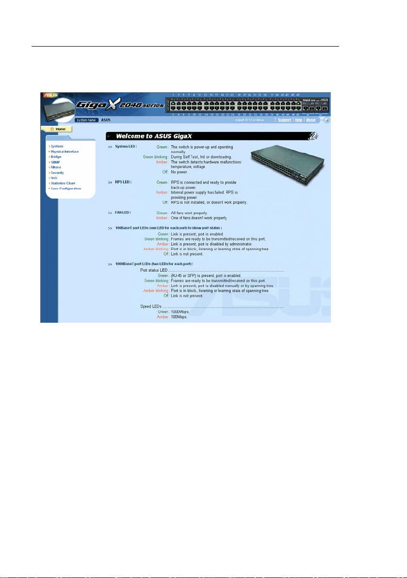
2.2 Front Panel
The front panel includes LE D indi cators that show t he syst em, RPS, fa n, and
port status.
Figure 2. Front panel (GigaX 2048)
Figure 3. Front panel (GigaX 2024)
Page 18

Table 1. Front panel labels and LEDs
Label Color Status Description
SYSTEM Green On Unit is powered on
RPS Green On
Amber On Abnormal temperature or voltage
Off
Amber On The PSU is abnormal and the switch is
Off
FAN Green On Both fans are working properly
10/100 ports Green On Ethernet link is established
Amber On Both or either one of the fans stopped
Off
Amber On Link is present, but port is disabled either
10/100/1000
port status
Green On
Off
Amber On Link is present, but port is disabled either
10/100/1000
port speed
Green On 1000Mbps
Amber On 100Mbps
Off
Flashing Self-test, INIT, or downloading
Flashing Data is being transmitted/received
Flashing Port is in one of the STP blocking, listening
Flashing Data is being transmitted/received
Flashing Port is in one of the STP blocking, listening
No power
The PSU is working properly and the switch
has a good redundant power supply
powered by RPS
No power at all (system LED is also off), RPS
does not work properly or not installed
(system LED is on)
No Ethernet link
manually or by spanning tree
and learning state
Link (RJ-45 or SFP) is present; port is
enabled
No Ethernet link
manually or by spanning tree
and learning state
10Mbps
18
Page 19
GigaX Series L2 Managed Switch User Guide
2.3 Rear Panel
The switch rear panel contains the ports for the data and power
connections.
Figure 4. Rear panel
Table 2. Rear panel labels
No. Label Description
1 Power Connector Connects to the supplied power cord
2 FAN1 – FAN2 Replaceable system fans
3 Console USB USB port for console management
4 Console RS232 RS-232 serial port for console management
5 RPS Redundant Power Supply connector
Page 20

2.4 Technical specifications
Table 3. Technical specifications
Physical Dimensions 43.5mm(H) X 444 mm (W) X 265mm(D)
Power Input Consumption
Redundant Power Input Output
Supply (RPS)
Environmental
Ranges
Replaceable Fans
100-240V AC/2.5A
50-60Hz
< 90 watts
100-240V AC/1.8A
50-60Hz
Temperature
Humidity 15 to 90% 0 to 95%
Altitude up to 10,000 ft 40,000 ft
Dimensions
40 x 40 x 20 mm 12VDC, 0.13A 8200RPM
12V DC/12.5A
Operating Storage
-10 to 50℃
122 ℉) (-40 to 158 ℉)
(3,000m) (12,000m)
Voltage and
Current
(14 to -40 – 70 ℃
Speed:
20
Page 21

GigaX Series L2 Managed Switch User Guide
3 Quick start guide
This section provides the basic instructions to set up the GigaX
environment. Refer also to the GigaX Series Installation Guide.
Part 1 shows you how to install the GigaX on a flat surface or on a
rack.
Part 2 provides instructions to set up the hardware.
Part 3 shows you how to configure basic settings on the GigaX.
Obtain the following inf orma tion fro m your net work ad ministrat or bef ore
proceeding:
IP address for the switch
Default gateway for the network
Network mask for this network
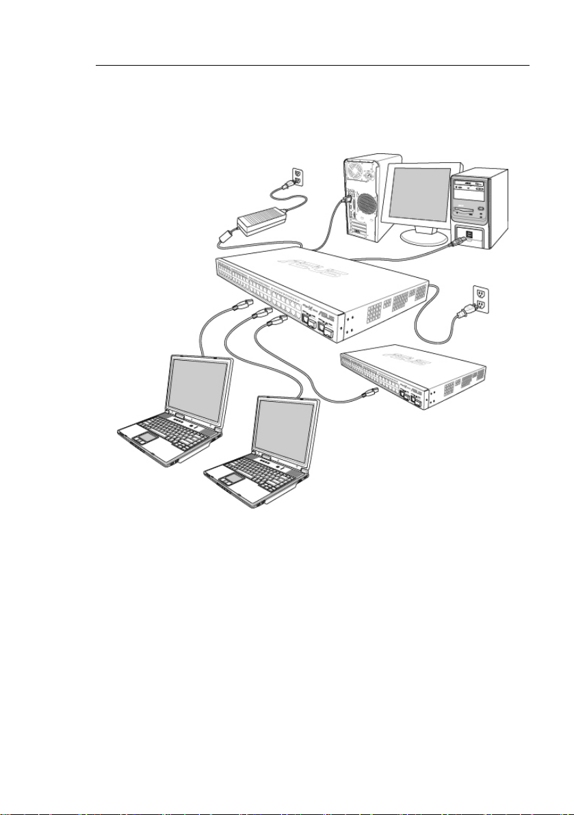
3.1 Part 1 — Installing the hardware
Connect the device to the power outlet, and your computer or network.
Figure 5 illustrates the hardware connections.
3.1.1 Installing the switch on a flat surface
The switch should be installed on a level surface that can supp ort the
weight of the switches and their accessories. Attach four rubber pads on
the marked location on the bottom of th e switch.
3.1.2 Mounting the switch on a rack
1. Attach brackets to each side of the switch and make the posts insert
to the switch.
2. Insert and tighten two screws to securely attach the bracket to the
rack on each side.
Page 22

GigaX Series L2 Managed Switch User’s Guide
3.2 Part 2 — Setting up the switch
Connect the device to the power outlet, and your computer or network. See
Figure 5.
3.2.1 Connect the console port
For console management, use an RS232 (DB9) or a USB cable to
connect the switch. If you want to use WEB interface, connect your PC
to the switch using the Ethernet cable.
3.2.2 Connect to the computers or a LAN
You can use Ethernet cable to connect computers dire ctly to the switch
ports. You can also conne ct hubs/ switche s to the swit ch port s by Ethe rnet
cables. You can use either the crossover or straight -through Ethernet cabl e
to connect computers, hubs, or switches.
Use a twisted-pair Category 5 Ethernet cable to connect the
1000BASE-T port. Otherwise, the link speed can not reach
1Gbps.
3.2.3 Attach the RPS module
Connect your RPS module to the RPS jack and make sure the other end of
the RPS is connected to the power cord. Connect to the power cord to a
grounded power outlet.
3.2.4 Attach the power adapter
1. Connect the AC power cord to the POWER receptacle on the ba ck
of the switch and plug the other end of the power cord into a wall
outlet or a power strip.
2. Check the front LED indicators with the descri ption in Table 4. If the
LEDs light up as described, the switch hardware is working
properly.
22
Page 23
GigaX Series L2 Managed Switch User Guide
Cat 5 Ethernet cables
LAN computers
Figure 5. Overview of Hardware Connections
RPS
RS-232
Console
Management
USB
Expansion
hub/switch
Page 24

GigaX Series L2 Managed Switch User’s Guide
Table 4. LED Indicators
No. LED Description
1 System Solid green indicates that the device is turned
2 Switch ports [1] to [50]
(2048) [1] to [26]
(2024)
3 RPS
4 Fan
on. If this light is off, check if the power
adapter if attached to the switch and plugged
into a power source.
Solid green indicates that the device can
communicate with the LAN, or flashing when
the device is sending or receiving data from
your LAN computer.
Solid green indicates that the device has
successfully installed an RPS module.
Solid green indicates that all fans work
properly
3.3 Part 3 — Basic switch setting for
management
After completing the hardware connections, configure the basic settings for
your switch. You can manage the switch using the following methods:
• Web interface: the switch has a set of pages to allow you to manage
it using Java
• Command Line Interface: use console port to manage the switch.
®
-enabled IE5.0 or higher version.
3.3.1 Setting up through the console port
1. Use the supplied crossover RS-232 cable to connect to the console
port on the back of the switch. This port is a male DB-9 connector,
implemented as a data terminal equipment (DTE) connection.
Tighten the retaining screws on the cable to secure it on the
connector. Connect the other end of the cable to a PC running
terminal emulation software. e.g Hyper Terminal.
2. Use the supplied USB cable to conn ect t o a PC. You have to install
the USB driver from the switch CD-ROM before the USB can work
properly. The USB drivers will simulate an additional COM port
under Windows Me/2K/XP OS.
24
Page 25

GigaX Series L2 Managed Switch User Guide
3. Make sure the settings of your terminal emulation software as
follows:
a) Choose the appropriate serial port number
b) Set the data baud rate to 115200 (or 9600 on some models)
c) Set the data format to no parity, 8 data bits and 1 stop bit
d) No flow control
e) Set VT1000 for emulation mode
4. After setting up the terminal, you can see the prompt “(ASUS)%” on
the terminal.
5. Type “login” to access the command line interface. The default u ser
name is “admin”. Skip the password by pressing <Enter>.
You can change the password at any time through CLI (see
section 5.3.1). To protect your switch from unauthorized
6. Follow these steps to assign an IP address to the switch:
a) Type “net interface ip sw0 <your ip address> <your network
mask>”. For example, if your switch IP is 192.168.10.1 and the
network mask is 255.255.255.0. Then you should type “net
interface ip sw0 192.168.10.1 255.255.255.0”.
access, you must change the default password as soon as
possible.
b) If the switch has to be managed across networks, then a
default gateway or a static route entry is required. Type “net
route static add 0.0.0.0 <your network gateway IP> 0.0.0.0 1”
as your default route entry, as shown in
Figure 6.
Figure 6. Login and IP setup Screen
Page 26
GigaX Series L2 Managed Switch User’s Guide
3.3.2 Setting up through the Web interface
To successfully connect your PC to the switch, your PC must a valid IP in
your network. Contact your network administrator to obtain a valid IP for the
switch. If you wish to change the def ault IP addres s of the swit ch, foll ow
section 3.3.1 to change the I P addre ss. Since th e switch does not support
DHCP client function, a valid static IP for the switch is necessary to use
Web interface.
1. It is not necessary to login Web interface at the first time to use Web
interface because the default configuration for Web access
authentication is disabled. To secure the system configuration,
please enable the authentication function at the “Administration”
page under “System” category. Skip step 2 if the authentication is
disabled.
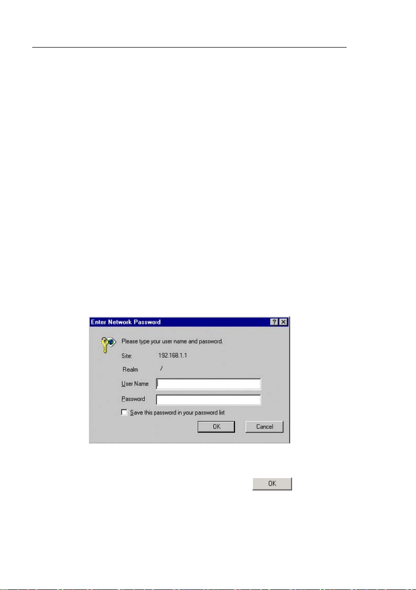
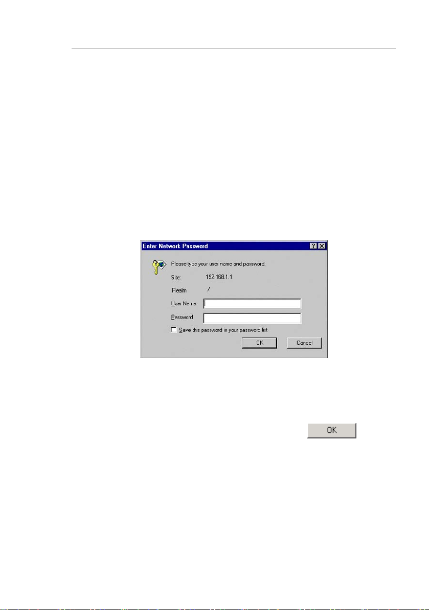
2. At any PC connected to the network that the switch can acce ss,
open your Web browser (Internet Explorer), and type the following
URL in the address/location box, and press <Enter>:
http://192.168.1.1
This is the factory defa ult IP address of the switch.
A login screen appears, as shown in Figure 7.
Figure 7. Login Screen
Enter your user name and password, a nd then click
Configuration Manager. Use the following defaults the first time you log into
this interface:
26
to enter the
Page 27

GigaX Series L2 Managed Switch User Guide
Default User Name: admin
Default Password: (no password)
You can change the password at any time (see section
5.3.1 System Commands).
3. To setup a new IP address, click “System”, then “IP Setup” (see
Figure 8). Fill in the IP address, network mask and default gateway,
then click
4. If your new address is different from the default, the browser can not
update the switch status window or retrieve any page. This is
normal. You have to retype the new IP address in the
address/location box, and press <Enter>. The WEB link returns.
5. To enable authentication for Web access, click “Administration” on
the menu list, then select “Enabled” to start the protection.
.
Note that the GigaX 2048 and 2024 models have the
same web interface, except for the front panel image on
top of the screen (see figures on the next page).
The following sections show only one screen image (that
of the GigaX 2048 model) if the screen contents for both
models are the same. Both the GigaX 2048 and 2024
screens are shown when the screen contents are
different.
A login window appears i mmedi ately afte r you click
figures on the next page.
. See the
Page 28
GigaX Series L2 Managed Switch User’s Guide
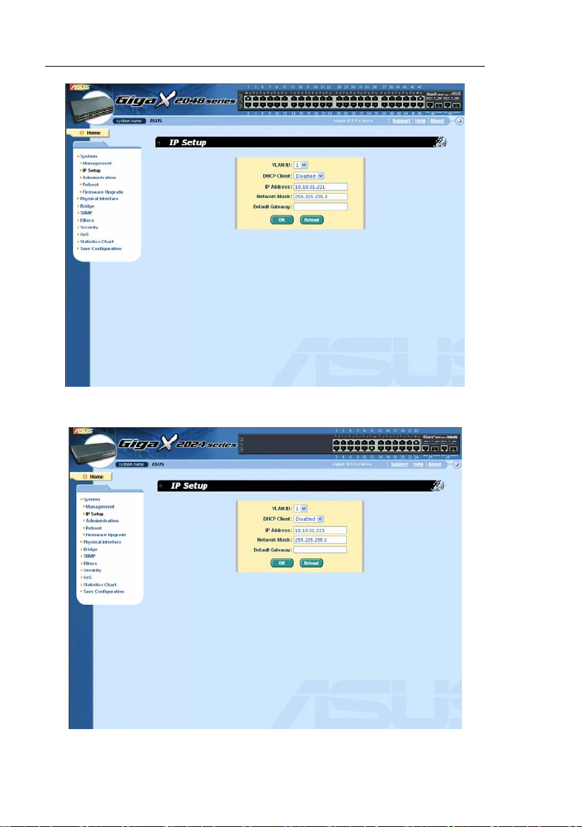
Figure 8. IP Setup (GigaX 2048)
28
Figure 9. IP Setup (GigaX 2024)
Page 29
GigaX Series L2 Managed Switch User Guide
4 Management with the W eb Interface
The switch provides Web pages that allow switch management through the
Internet. The program is designed to work best with Microsoft Internet
Explorer® 5.5, or later versions. NOTE: Netscape is not supported.
4.1 Log into Web user interface
1. From a PC, open your web browser, type the following in the web
address (or location) box, and press <Enter>:
http://192.168.1.1
This is the factory default IP address for the switch. A login screen displays,
as shown in
Figure 10.
Figure 10. Configuration manager login screen
Note: Log in is not required if you do not ena ble web access authenti cation
(see 3.3.2).
2. Enter your user name and password, then click
Use the following defaults the first time you log into the program.
You can change the password at any time through CLI interface
(see section 5.3.1on page 104).
Default User Name:
Default Password:
admin
<no password>
.
Page 30
GigaX Series L2 Managed Switch User’s Guide
The home page appears each ti me you lo g into th e prog ram. (S ee the
following figures.)
Figure 11. Home page (GigaX 2048)
30
Page 31

GigaX Series L2 Managed Switch User Guide
Figure 12. Home page (GigaX 2024)
Page 32

GigaX Series L2 Managed Switch User’s Guide
4.2 Functional layout
Typical web page consists of three separate frames. The top frame has a
switch logo and front panel as shown in Figure 13 and Figure 14. Thi s
frame remains on the top of the browser window all the times and updates
the LED status periodically. See Table 4 for the LED definit ions. See Table
5 for the color status description.
Figure 13. Top frame (GigaX 2048)
Figure 14. Top frame (GigaX 2024)
Table 5. Port color description
Port Color Description
Green port Ethernet link is established
Black No Ethernet link
Amber port Link is present but port is disabled manually or by spanning tree
Clicking on the port icon of t he switch display s the p ort conf iguratio n in the
lower right frame.
The left frame, a menu fram e as shown in
Figure 15, contains all the
features available for switch configurat ion. These features are groupe d into
categories, e.g. System, Bridge, etc. You can click on any of these to
display a specific configuration page.
32
Page 33

GigaX Series L2 Managed Switch User Guide
Figure 15. Expanded Menu List
The above frame displays configuration pages or graphics for the
statistics. See section
4.3 for details.
Page 34

GigaX Series L2 Managed Switch User’s Guide
4.2.1 Menu navigation tips
• To expand a group of related menus, click on the correspondi ng
group name. The
sign will change to after expansion.
• To contract a group of related menus: click on the corresponding
group name. The
sign will appear next to the group name.
• To open a specific configurat ion page, click on th e desire d menu
item.
4.2.2 Commonly used buttons and icons
The following table describes the function for each button and icon used in
the application.
Table 6. Commonly used buttons and icons
Button/Icon Function
Stores any changes you have made on the current page.
Adds the existing configuration to the system, e.g. a static MAC
address or a firewall ACL rule and etc.
Modifies an existing entry
Modifies the existing configuration in the system, e.g. a static route
or a filter ACL rule and etc.
Deletes the selected item, e.g. a static route or a filter ACL rule and
etc.
Re-displays the current page with updated statistics or settings.
34
Page 35

GigaX Series L2 Managed Switch User Guide
4.3 System Pages
System pages include management, IP setup, administration, reboot, and
firmware update function.
4.3.1 Management
The Management page contain s the foll owing i nformation:
Model Name: product name
MAC Address: switch MAC address
System Name: user assigned name to identify the system (editable)
System Contact (editable)
System Location (editable)
To save any changes and make it effective immediately, click
Use
to refresh the setting, as shown in Figure 16.
.
Page 36

GigaX Series L2 Managed Switch User’s Guide
Figure 16. Management
36
Page 37

GigaX Series L2 Managed Switch User Guide
4.3.2 IP Setup
The switch supports dynamic IP and static IP assignment. The dynamic IP
can be got from a DHCP server within the same VLAN. The IP Setup page
contains the following edita ble informat ion:
VLAN ID: Specify a VLAN ID to system management interface. It is
necessary to be within the same VLAN for management.
IP Address: Assign a static IP address to the switch management
interface.
Network Mask
Default Gateway
To save any changes and make it effective immediately, click
Use
to refresh the setting, as shown in Figure 17.
.
Page 38

GigaX Series L2 Managed Switch User’s Guide
Figure 17. IP Setup
38
Page 39

GigaX Series L2 Managed Switch User Guide
4.3.3 Administration
The Administration page al lows you t o enable or disa ble the
authentication for web user by password prot ection. The def ault setting fo r
web access does not require any authent ication.
To save any changes and make it effective immediately, click
Use
to refresh the setting, as shown in Figure 18. When you
enable the password protection, you have to login again immediately.
You can change the password at any time through the CLI
interface.
.
Figure 18. Administration
Page 40

GigaX Series L2 Managed Switch User’s Guide
4.3.4 Reboot
The Reboot page contains a button. Clicking the button to reboot
the system.
Figure 19. Reboot
Rebooting the system stops the network traffic and
terminates the Web interface connection.
4.3.5 Firmware Upgrade
The Firmware page contains the following information:
Hardware Version: shows the hardware revision number.
Boot ROM Version: shows the version of the boot code
40
Page 41

GigaX Series L2 Managed Switch User Guide
Firmware Version: shows the current running firmware version. Thi s
number will be updated after the firmware update.
Enter the firmware location into the firmware space directly, or cl ick
to choose the file name of the firmware from prompt window.
Click
to update the switch firmware. See Figure 20 for reference.
Clicking the upload button loads the assigned firmware to the
switch, then reboot system after a successful firmware
update. You have to re-login to Web interface again
Figure 20. Firmware Upgrade
Page 42

GigaX Series L2 Managed Switch User’s Guide
4.4 Physical Interface
The Physical Interface displays the Ethe rnet port statu s in real time. You
can configure the port in following fields:
Port: select the port to configure
Admin: disable/enable the port
Mode: set the speed and duplex mode
Flow Control: enable/disable 802.3x flow control mechanism
Port Status Window: displays the following information for each port
a) Link status: the link speed and duplex for an existing link,
otherwise link is down
b) State: the STP state
c) Admin: the setting value to disable or enable the port
d) Mode: the setting value for link speed and duplex mode
e) Flow Control: the setting value to enable or disable 802.3x
flow control mechanism
Select the corresponding port number and configure the port setting, then
click on the
of the display window. However, the new settings do not take effect until
the “Save Configuration” is executed.
42
button. The field you change will update t he conte nt
Page 43

GigaX Series L2 Managed Switch User Guide
Figure 21. Physical Interface
4.5 Bridge
The Bridge page group contains most layer 2 configurations, like link
aggregation, STP....etc..
Spanning Tree
The configuration page for S panning Tree Protocol can disable a nd enable
the feature in runtime. This p age consi sts of thre e part s.
The first part shows the root information. It tells user the STP setting a bout
the root switch.
The second part is the STP setting. The following options are avail able:
Disable/STP Enabled/RSTP Enabled: Turn the STP/RSTP off/on.
When you turn the STP/RSTP on, STP/RSTP will use the following
settings if the switch is the root switch.
Hello Time: the interval between the generation of configuration
BPDU
Page 44

GigaX Series L2 Managed Switch User’s Guide
Max Age: a timeout value to be used by all Bridges in the LAN
Forward Delay: a timeout value to be used by all bridges in the LAN
Bridge Priority: the switch priority in the LAN
The third part is the port sett ing. It conta ins a disp lay window t o show the
current configuration for each p ort. You cli ck
setting for STP/RSTP. The following fields are available:
Port: select the corresponding port to configure
Priority: the port priority in the switch. Low numeric value indicates a
high priority. The port with lower priority is more likely to be blocked
by STP if a network loop is detected. The valid value is from 0 to 240.
Path Cost: the valid value is from 1 to 200000000. The higher cost is
more likely to be blocked by STP if a network loop is detected.
Edge Port: All ports are set to be edge ports by default. Edge port
becomes STP port when BPDU is received. Also, it takes very short
time for an edge port to be in forwarding state.
Point to Point: Auto/Yes/No. A full duplex link is considered as a
point to point link. Otherwise, it is a shared link. Point to point link
may have less convergence time. Auto is recommended in most
cases.
Click
settings to the current value.
to make the settings effective. Click to refresh the
to change the port
44
Page 45

GigaX Series L2 Managed Switch User Guide
Figure 22. Spanning Tree
4.5.1 Link Aggregation
The page configures the link aggregation group (port trunking). The
switch can have 6 link aggregation groups.
Show Trunk: Select “Add a new Trunk” for a new created gro up. Or
select an existed group to display on the following fields and port
icons.
Port Selection Criterion: the algorithm to distribute packets among
the ports of the link aggregation group according to source MAC
address, destination MAC address, source and destination MAC
address, source IP address, destination IP address, or source and
destination IP address.
Name: the group name.
Page 46

GigaX Series L2 Managed Switch User’s Guide
Trunk ID: a number to identify the trunk group besides the group
name.
LACP: Enable/Disable LCAP on selected trunk. LACP mode is fixed
to be Active.
Remove Trunk: Remove the selected trunk.
Port Icons: these port icons are listed in a way like the front panel.
You have to click on the icon the select the group members. The
port can be removed from the group by clicking the selected port
again.
Click
to make the setting send to the switch (HTTP serv er). Cli ck
to refresh the settings to current value. To make the configuration
effective, go to “Save Configuration” page, then click
.
You have to check the runtime l ink spee d and du plex mod e to make sure
the trunk is physically active. Go t o Physical Interface and check the link
mode in the runtime statu s window f or the tru nk port s. If all the t runk
members are in the same speed and full duplex mode, then the trunk group
is set up successfully. If one of the members is not in the same speed or full
duplex mode, the trunk is not set correctly. Che ck the li nk part ner a nd
change the settings to have the same speed and full duplex mode fo r all
the members of your trunk group.
• All the ports in the link aggregation group MUST operate
in full-duplex mode at the same speed.
• All the ports in the link aggregation group MUST be
configured in auto-negotiation mode or full duplex mode.
This configuration will make the full duplex link possible. If
you set the ports in full duplex force mode, then the link
partner MUST have the same setting. Otherwise the link
aggregation could operate abnormally.
• All the ports in the link aggregation group MUST have the
same VLAN setting.
• All the ports in the link aggregation group are treated as a
single logical link. That is, if any member changes an
46
Page 47

GigaX Series L2 Managed Switch User Guide
attribute, the others will change too. For example, a trunk
group consists of port 1 and 2. If the VLAN of port 1
changes, the VLAN of port 2 also changes with port 1.
Figure 23. Link aggregation (GigaX 2048)
Page 48

GigaX Series L2 Managed Switch User’s Guide
Figure 24. Link aggregation (GigaX 2024)
4.5.2 Mirroring
Mirroring, together with a network traffic analyzer, helps you monitor
network traffics. You can monitor the sele cted ports for egress o r ingress
packets.
Mirror: Selects the mirror group. Each group consists of 24 Fast
Ethernet ports and one Gigabit port. (for GigaX 2048 only)
Mirror Mode: Enables or disables the mirror function for the
selected group.
Monitor Port: Receives the copies of all the traffics in the selected
mirrored ports.
GigaX 2048 has two monitor ports. Each port can monitor 24 Fast
Ethernet ports and one Gigabit port.
GigaX 2024X has only one monitor port. The port can monitor 24
Fast Ethernet ports and two Gigabit ports.
48
Page 49

GigaX Series L2 Managed Switch User Guide
The monitor port can not belong to any link aggregation group.
The monitor port can not operate as a normal switch port. It does
not switch packets or do address learning.
Click to make the setting send to the switch (HTTP serv er). Cli ck
to refresh the settings to cu rrent value.
Figure 25. Mirroring page (GigaX 2048)
Page 50

GigaX Series L2 Managed Switch User’s Guide
Figure 26. Mirroring page (GigaX 2024)
50
Page 51

GigaX Series L2 Managed Switch User Guide
4.5.3 Static Multicast
This page can add multicast addresses into the multicast table. The switch
can hold up to 256 multicast entries. All t he ports in the group will fo rward
the specified multicast packets to other ports in the group.
Show Group: selects “Add a new Group” to enter a new entry, or
select an existing group address to display
MAC Address: selects the multicast address
VLAN: selects the VLAN group
CoS: assigns the priority for Class of Service
Click
settings to current value.
to make the setting effective. Click to refresh the
Figure 27. Static Multicast (GigaX 2048)
Page 52

GigaX Series L2 Managed Switch User’s Guide
Figure 28. Static Multicast (GigaX 2024)
4.5.4 IGMP Snooping
IGMP snooping helps reduce the multicast traffics on the network by
allowing the IGMP snooping function to be turned on or off. When turned
on, the switch snoops the IGMP packets and puts the new group into the
multicast table. However, if the static e ntries o ccupy all 25 6 space s, the
IGMP snoop does not work normally. The swit ch only all ows 256-laye r 2
multicast group.
52
Page 53

GigaX Series L2 Managed Switch User Guide
Figure 29. IGMP Snooping
4.5.5 Traffic Control
Traffic control prevents the switch bandwidth from flooding packets
including broadcast packets, multicast packets and the unicast packets
because of destination address lookup failure. The limit number is a
threshold to limit the total n umber of t he checked typ e packet s. For
example, if broadcast and multicast a re enabled, the tota l traffic amount f or
those two types will not ex ceed the limit value. Cli ck
new configuration. To make the configuration eff ective, go to “Save
Configuration” page, then click
.
to save th e
Page 54

GigaX Series L2 Managed Switch User’s Guide
Figure 30. Traffic Control
4.5.6 Dynamic Addresses
This page displays the result of dynamic MAC address lookup by port,
VLAN ID, or specified MAC address. The dynamic address is the MAC
address learned by switch, it will age out from the address table if the
address is not learned again during the age time. User can set the age time
by entering a valid number from 10 to 1,000,000 in seconds. Th en click on
to save the new age value. To make the configuration effectiv e,
please go to “Save Configuration” page, then click on
You can look up MAC addresses by checking the port, VLA N ID, or/and
MAC address, then click on
the result of the query.
54
. The address window will display
.
Page 55

GigaX Series L2 Managed Switch User Guide
Figure 31. Dynamic Address
Page 56

GigaX Series L2 Managed Switch User’s Guide
4.5.7 Static Addresses
You can add a MAC address int o the swi tch address t able. T he MAC
address added by this way will not age out from the address table. We call
it static address.
MAC Address: enter the MAC address
VLAN ID: enter the VLAN ID that the MAC belongs
Port Selection: select the port to which the MAC belongs
Discard: you can do packet filtering when the MAC address appears
in the packets as destination address, source address, or either of
them.
56
Page 57

GigaX Series L2 Managed Switch User Guide
Click on the when you create a new static MAC address by the
above information. Then you will see the new added entry shows in the address
window. You can remove the existed address by selecting the entry with the
mouse, then clicking on
MAC address entries. Click
the settings to current value. To make the configuration effective, please go to
“save configuration” page, then click
. The button updates the existed
to save effective. Click to refresh
.
Figure 32. Static Address
4.5.8 Tagged VLAN
You can set up to 255 VLAN groups and show VLAN group in this page.
There is a default VLAN created by the switch. It cannot be removed at all.
This feature prevents the switch from malfunction. Yo u can remove any
existed VLAN except the def ault VLAN.
You can assign the port to be a tagged port or an untagged port by toggling
the port button. There are three typ es of butt on di splay as fo llows:
“U” type: untagged port that will remove VLAN tags from the
transmitted packets.
Page 58

GigaX Series L2 Managed Switch User’s Guide
“T” type: All packets transmitted from this port will be tagged.
“blank” type: This port is not a member of the VLAN group.
If one untagged port belongs to two or more VLAN groups at the same time,
it will confuse the switch and cause flooding traffics. To prevent it, the
switch only allows one untagged port belongs to one VLAN at the same
time. That is, the untagged port belongs to the VLAN group which is called
“PVID” and configured in the “Default Port VLAN & CoS ” page. If you want
to assign an untagged port from one VLAN to another, you have to remove
it from the original VLAN, or change it to be tagged in t he origin al VLAN
first.
Show VLAN: select the existed VLAN to display or select “Add a
new VLAN” to create a new VLAN group
Name: the VLAN name
DHCP Snoop: Enable or disable DHCP snooping on this VLAN.
VLAN ID: this field requires user to enter the VLAN ID when a new
VLAN is created
Remove VLAN: Remove an existed VLAN. This field disappears in
VLAN creation page.
Click on
effective, go to “Save Configuration” page, then click on
58
to save the configuration. To make the configuration
.
Page 59

GigaX Series L2 Managed Switch User Guide
Figure 33. Tagged VLAN (GigaX 2048)
Figure 34. Tagged VLAN (GigaX 2024)
Page 60

GigaX Series L2 Managed Switch User’s Guide
4.5.9 Default Port VLAN and CoS
Some VLAN tag related field settings fo r each port are included in thi s page.
It includes:
Port: select the port to configure
PVID: port-based VLAN ID. Every untagged packet received from
this port will be tagged with this VLAN group ID
CoS (Class of Service) value: every untagged packet received from
this port will be assigned to this CoS in the VLAN tagged
Click on
to save the configuration. To make the configur ation effectiv e, go
to “Save Configuration” page, then click
to change the content in the port list window. Click on
Figure 35. Default Port VLAN and CoS
.
60
Page 61

GigaX Series L2 Managed Switch User Guide
4.5.10 DHCP Snooping
DHCP snooping is a DHCP security feature that provides security by
filtering untrusted DHCP messages and by buildi ng and maintai ning a
DHCP binding table. You can assign some port s to be tr usted port s. The
selected (trusted) port forwards the DHCP packets as a normal port, but
the DHCP ACK packets will be dropped when the unsele cted (untrust ed)
port receives the packets.
DHCP Snooping: enable or disable DHCP snooping.
Figure 36. DHCP Snooping (GigaX 2048)
Page 62

GigaX Series L2 Managed Switch User’s Guide
Figure 37. DHCP Snooping (GigaX 2024)
4.6 SNMP
This group offers the SNMP conf iguratio n inclu ding Communi ty Table,
Host Table, and Trap Setting. To prov ide more secure mana gement and
access control, SNMPv3 is supported.
4.6.1 Community Table
You can type different community names and specify whether th e
community has the privilege to make setting (write access) by checking the
box. Click
to refresh the page.
62
to save the configuration permanently or
Page 63

GigaX Series L2 Managed Switch User Guide
Figure 38. Community Table
Page 64

GigaX Series L2 Managed Switch User’s Guide
4.6.2 Host Table
This page links host IP address to the community name that is entered in
Community Table page. Type an IP address and select the community
name from the drop-down list. Clic k
permanently or
to refresh the page.
Figure 39. Host Table
to save the configuration
64
Page 65

GigaX Series L2 Managed Switch User Guide
4.6.3 Trap Setting
By setting trap destination IP add resses and community names, y ou can
enable SNMP trap function to send trap packets in different versions (v1 or
v2c). Click
to refresh the page.
to save the configuration permanently or
Figure 40. Trap Setting
4.6.4 VACM Group
VACM (View-based Access Control Model) Group is used to configure the
information of SNMPV3 VACM Group.
Group Name: enter the security group name.
Read View Name: enter the Read View Name that the Group
belongs. The related SNMP messages are Get, GetNext, GetBulk.
Write View Name: enter the Write View Name that the Group
belongs. The related SNMP message is Set.
Page 66

GigaX Series L2 Managed Switch User’s Guide
Notify View Name: enter the Notify View Name that the Group
belongs. The related SNMP messages are Trap, Report.
Security Model: enter the Security Model Name that the Group
belongs. Any is suitable for v1, v2, v3. USM is SNMPv3 related.
Security level: enter the Security level Name that the Group belongs.
Only NoAuth, AuthNopriv, AuthPriv can be chosen.
Click on the
when you create a new VACM grou p entry by th e
above information. Then you will see the new added entry shows in the
group window. You can remove the existed group by selecting the entry
with the mouse, then clicking on
the existed VACM Group entries. Click
. The button updates
to save effectively. Click
to refresh the settings to current value. To make the
configuration effective, please go to "Sav e Configurati on" page, then cli ck
on
.
66
Figure 41. VACM Group
Page 67

GigaX Series L2 Managed Switch User Guide
4.6.5 VACM View
VACM (View-based Access Control Model) View is used to view the
information of SNMPV3 VACM Group.
View Name: enter the security group name.
View Type: Select the View Type that the view belongs. Included or
Excluded when View Subtree matches the Oid in the SNMPv3
message.
View Subtree: enter the View Subtree that the View belongs. The
Subtree is the Oid to match the Oid in the SNMPv3 message. The
match is good when the subtree is shorter than the Oid in the
SNMPv3 message.
View Mask: enter the View Mask that the View belongs. Each bit in
the mask represents the digit between the dots of View Subtree
from left side. Bit ‘0’ means ‘don’t care’.
Click on the
above information. Then you will see the new added entry shows in the
view window. You can remove the existe d views by selecting the e ntry with
the mouse, then clicking on
existed VACM View entries. Cli ck
to refresh the settings to current value. To make the
configuration effective, please go to "Sav e Configurati on" page, then cli ck
on
.
when you create a new VACM View entry by the
. The button updates the
to save effective. Click
Page 68

GigaX Series L2 Managed Switch User’s Guide
Figure 42. VACM View
4.6.6 USM User
USM (User-based Security Model) User is used to configure the
information of SNMPV3 USM User.
Engine Id: enter the Engine Id that should match the ID in the
Manager.
Name: enter Name combined with Engine ID that should match the
Name and Engine ID in the Manager.
Auth Protocol: enter the Auth Protocol that Engine ID and Name
belong. Only NoAuth, MD5, SHA1 can be chosen. If the NoAuth is
chosen, there is no need to enter password.
Auth Password: enter the password that the Auth Protocol belongs.
The password needs at least 8 characters or digits.
68
Page 69

GigaX Series L2 Managed Switch User Guide
Priv Protocol: enter the Priv Protocol that Engine ID and Name
belong. Only NoPriv, DES can be chosen. If the NoPriv is chosen,
there is no need to enter password.
Priv Password: enter the password that the Priv Protocol belongs.
The password needs at least 8 characters or digits.
Click on the
when you create a new USM User entry by the
above information. Then you will see the new added entry shows in the
User window. You can remove the existed User by selectin g the entry with
the mouse, then clicking on
existed USM User entries. Clic k
. The button updates the
to save effective. Click
to refresh the settings to current value. To make the
configuration effective, please go to "Sav e Configurati on" page, then cli ck
on
.
Figure 43. USM User
Page 70

GigaX Series L2 Managed Switch User’s Guide
4.7 Filters
The switch can filter certain traffic types accordi ng to packet header
information from Layer 2 to Layer 4. Each filter set includes a couple of
rules. You have to attach the filter set to certain port s to make the filter
work.
4.7.1 Filter Set
You can create a filter set by giving a name, ID and a mode of rules. The
switch defines two modes of rule s, one i s MAC m ode and t he oth er is IP
mode. Only the same mode of rules can bundle together to form a filter set.
Each mode has different fields to configure. F or exa mple, you can use IP
mode rule to filter FTP packets.
When you click on the Filter Set, the Filter Set page appears (Figure 44).
First, create a filter set by typing a name and ID, then clicking on
Second, click on the
Third, click on
to remove the filter set. You have to follow the rules to make a
valid filter set.
• One set consists of a type of rules. The rules having the same fields
to filter packets belong to one type. For example, two rules filt er
packets with two destination IP addresses, then they are the same
type. But a rule filtering source IP address does not belong to t he
same type.
• Four types of rules can apply to ports at the same time. If there are
more than four types, the system automatically di sables the rule s.
button to select the set you want to edit or remove.
to enter the rule page as Figure 45, or click on
.
70
Page 71

GigaX Series L2 Managed Switch User Guide
Figure 44. Filter Set
The Filter Rule page provides options for rule modes, one is MAC rule
(Figure 45) and the other i s IP rule (Figure 46). If you did not enter the MAC
address in the blank box, it means the rule doesn’t care the MAC value. In
IP rule setup, you can enter any of the 5 tuples, source IP, destinatio n IP,
protocol, source application port and de stinatio n applicatio n port. The
Action field determines if the packet should be dropped or forwarding
when it matches the rule. If a packet matches two rules with different action,
the packet will follow the rule showed first in the rule list.
Page 72

GigaX Series L2 Managed Switch User’s Guide
Figure 45. Filter Rule in MAC mode
72
Figure 46. Filter Rule in IP mode
Page 73

GigaX Series L2 Managed Switch User Guide
4.7.2 Filter Attach
A filter set is idle if you did not atta ch it to any in gress or egress port. Use
the Filter Attach page to attach a filter set to ingress and egress ports.
Click
effective, go to the “Save Configuration” page, the n click
on
to save the configuration. To make the configurati on
, or click
to refresh the page.
To attach a filter set to ports:
• Attach to all ports: the filter set applies to all the ports of the system.
• Attach to certain ports: you can specify the ingress ports and egress
port to be applied.
• Detach from all ports: remove all t he filters from the att ached ports.
You may not detach certain ports after issuing an "Attach All"
command. If you wish to detach ports, use the "Detach All"
command.
Once the filter set is attached to the ingress ports and egress ports, it will
filter the packets according to the ingress port, egress port, and the packet
fields in the rules. For examp le, a set with a sin gle rule to filter out
destination MAC addres s 00:10: 20:30:40: 50 is att ached to ingres s port 1
and egress port 2. A packet with destination MAC 00:10: 20:30:40: 50 from
port 1 is not switched to port 2, b ut it is pos sible t o go to oth er ports except
port 2 in flooding situation.
Page 74

GigaX Series L2 Managed Switch User’s Guide
Figure 47. Filter Attach (GigaX 2048)
74
Figure 48. Filter Attach (GigaX 2024)
Page 75

GigaX Series L2 Managed Switch User Guide
4.8 Security
The switch has the 802.1x port-based security feature. Only authorized
hosts are allowed to access the switch port. Traffic is blocked for hosts
failed to authenticate themselves. The authentication service is provided by
a RADIUS server or the local database (support MD5 authentication) in the
switch.
The switch also supports dynamic V LAN assign ment throu gh 802.1x
authentication process. The VLAN information for the users/ports should
be configured in the authentication server properly before enabling this
feature.
The switch has the port security feature. Users can use the port security
feature to restrict input to an interface by limiting and id entifying MAC
addressed of the stations allo wed to acce ss the p ort. When y ou assign
secure MAC addresses to a secure port, the port does not forward with
source addresses outside the group of defined addresses.
4.8.1 Port Access Control
Port Access Control is used to configure various 802.1x parameters.
802.1x uses either RADIUS server or local database to authenticate
port users.
The first part is the Bridge (Global) settings:
• Reauthentication: Once enabled, the switch will try to authenticate
the port user again when the re-authenti cation tim e is up.
• Reauthentication Time: If 'Reauthenti cation' i s enabled, t his is the
time period the switch uses to re-send aut henticati on reque st to the
port user. (See above)
• Authentication Method: RADIUS or Local database can be used to
authenticate the port user.
• Quiet Period: If authentication failed eith er from RADIUS or local
database, the switch waits upon this time period before sending
another authentication request to the port user.
• Retransmission Time: If the port user failed to respond to
authentication request from the switch, the switch waits upon this
time period before sending another authentication request to the port
user.
Page 76

GigaX Series L2 Managed Switch User’s Guide
• Max Reauthentication Attempts: Retry count if the port user failed to
respond to authentication requests from the switch.
The second part is the port settings. Please click
done with the modifications.
• Port: Specify which port to configure.
• Multi-host: If enabled, ALL hosts connected to the selected port are
allowed to use the port if ONE of the hosts pa ssed the authentication.
If disabled, only ONE host among other hosts passed the
authentication is allowed to use th e port.
• Authentication Control: If 'force_authorized' is selected, the sel ected
port is forced authorized. Thus, t raffic from all host s is allo wed to
pass. Otherwise, if 'force_unauthorized' is selected, the selected port
is blocked and no traffic can go thro ugh. If 'A uto' is sel ected, t he
behavior of the selected port is controlled by 802.1x protocol. All
ports should be set to 'Auto' under normal conditions.
• Guest VLAN: Specify a guest VLAN to clients that are not
802.1x-capable.
Click
refresh the settings to current value.
to make the settings permanent. Click to
when you're
76
Page 77

GigaX Series L2 Managed Switch User Guide
Figure 49. Port Access Control
Page 78

GigaX Series L2 Managed Switch User’s Guide
4.8.2 Dial-In User
Dial-in User is used to define users in the local database of the switch.
• User Name: New user name.
• Password: Password for the new us er.
• Confirm Password: Enter the password again.
• Dynamic VLAN: Specify the VLAN ID assigned to the
802.1x-authenticated clients.
Click
with the modifications. Click
selected user. Click
to add the new user. Click when you're done
to refresh the settings to current value.
when you want to remove the
to make the settings permanent. Click
78
Figure 50. Dial-In user
Page 79

GigaX Series L2 Managed Switch User Guide
4.8.3 RADIUS
In order to use external RADIUS server, the following parameters are
required to be setup:
• Authentication Server IP: The IP address of the RADIUS server.
• Authentication Server Port: The port number for the RADIUS server
is listening to.
• Authentication Server Key: The key is used for communications
between GigaX and the RADI US server.
• Confirm Authentication Key: Re-type the key e ntered above.
The VLAN of the RADIUS server connected to the switch must be
the same as the VLAN of the system management interface.
Click to make the settings permanent. Click to
refresh the settings to current value.
Page 80

GigaX Series L2 Managed Switch User’s Guide
Figure 51. RADIUS
80
Page 81

GigaX Series L2 Managed Switch User Guide
4.8.4 Port Security
Port security pages include port configurati on, port status, and secure MA C
addresses function.
4.8.4.1 Port Configuration
This page is used to configure various Port Security parameters. The total
number of available secure MAC addresses on the switch is 1024. Users
can configure the port in the following field:
• Port: select the port to make configuration.
• Admin: disable/enable port security feature on the port .
• Violation Mode: set the violation mode. This action will be taken
when a violation occurs. It is a security v iolation when the m aximum
numbers of secure MAC addresses have been added to the address
table, and a station whose MAC address is not in the addre ss table
attempts to access the interface. Yo u can conf igure t he interf ace for
one of three violation modes:
a) Protect: In this mode, you are not notified that a security
violation has occurred.
b) Restrict: In this mode, you are notified that a security violation
has occurred. Specifically, an SNMP trap is sent, a syslog
message is logged, and the violation counter increments.
c) Shutdown: In this mode, a port security violation causes the
interface to become blocking state immediately. It also sends
an SNMP trap, logs a syslog message, and increments the
violation counter.
• Max MAC Addresses: set the maximum numbers of secure MAC
addresses. The valid value i s from 1 to 132. The sum of this v alue for
all ports is less than or equal to the maximum number of secure
MAC address allowed in the switch.
• Aging Time: set the aging time. The valid value is from 0 to
1440(mins). The aging mechanis m is only effective f or d ynamic
secure MAC addresses. If the ti me is 0, th e aging m echani sm is
disabled for this port.
• Aging Type: set the aging type. To determine the action when the
dynamic secure MAC addresses are aged out. Two types of aging
are supported for each port:
Page 82

GigaX Series L2 Managed Switch User’s Guide
a) Absolute: the secure addresses on the port are deleted after
the specified aging time.
b) Inactivity: the secure addresses on the port are deleted only if
there is no data traffic from the secure source MAC address
for the specified time period.
Select the corresponding port number and configure the port setting, then
click on the
update automatically as you make changes. Click on
the setting effective. Click on
current value.
button. The content of the display window will
to make
to refresh the settings to the
Figure 52. Port Configuration
4.8.4.2 Port Status
This page displays the port secu rity info rmation of al l ports. T he security
information is as follows:
82
Page 83

GigaX Series L2 Managed Switch User Guide
• Port: port number.
• Status:
a) NoOper: this indicates port security of the port that is
configured to be disabled.
b) SecureUp: this indicates the port security is operational.
c) SecureDown: this indicates the port security is not operational.
This happens when the port security is configured to be
enabled but can not be operational due to some reasons su ch
as it conflicts with other features.
d) Restrict: this indicates that the port security violation occurs
when the violation mode is ‘restrict’.
e) Shutdown: this indicates that the port is shutdown due to port
security violation when the violation mode is ‘shutdown’.
• Restart: whether to restart the port in shutdown status(Yes/No).
• TotalMacAddrCount: the total numbers of current static and dy namic
secure MAC addresses.
• StaticMacAddrCount: the total numbers of current static secure MAC
addresses.
• ViolationCount: the total numbe rs of secu re violatio n.
Port security status on the port is ‘SecureDown’ when one of the
following situations occur:
• The port is link down.
• Administrative bridge port is disabled.
• The port is a trunk port.
• The port is a monitor port in port mi rroring.
• The port is running 802.1x and in the single-host mode .
If the status of a port is 'Shutdown', users can sele ct the corresponding port
number and set Restart to 'Yes', then click on th e
field you changed will update the content of the displ ay window. Click on
to make the setting effective. Click on to refresh the
settings to current value.
button. The
Page 84

GigaX Series L2 Managed Switch User’s Guide
Figure 53. Port Status
4.8.4.3 Secure MAC Addresses
Users can add a MAC address i nto the secure MAC addre ss table of one
port. The MAC address added in this way will not age out from th e secure
MAC address table. We call it static secure MAC address.
• MAC Address: enter the MAC address.
• Port Selection: select the port to which the MAC belongs.
84
Page 85

GigaX Series L2 Managed Switch User Guide
Click on after you create a new static MAC address in the
above way. Then you will see the newly added entry shown in the
address window.
Users can select one port from Port Selection, then click on
You will see the current total secure MAC addresses of the port shown
in the address window.
Users can remove the existed address by selecting the entries with the
mouse, then click on
to remove them. When you want to
select multi-entries, please press 'Shift' key on the keyboard and
selecting the entries with the mouse.
Click
or to make the configuration effective
immediately.
.
Figure 54. Secure MAC Address
Page 86

GigaX Series L2 Managed Switch User’s Guide
4.9 QoS
When you configure the QoS feat ure, you can select specifi c network traffic
to prioritize it according to its importance. It makes the network
performance more predictabl e and the bandwidth utilization more effective.
QoS pages include trust state, mapping, class set, policy set, policy attach,
and CoS function.
4.9.1 Trust State
This page is used to configure packets classif ication usi ng port trust states.
Users can configure the port in following field:
• Port: select the port to make configuration.
• State: set the trust state. Three types of state are supported fo r each
port.
a) No
No trust state to classify ingress packets
b) CoS
Classifies ingress packets with the packet CoS values.
For tagged IP packets -- the DSCP value of the packet is
modified based on the CoS-to-DSCP map.
For untagged IP packets -- the DSCP value of the packet is
modified based on the default port CoS-to-DSCP map.
c) DSCP
Classifies ingress packets with the packet DSCP values.
For tagged non-IP packets -- the packet CoS value is set to 0.
For untagged non-IP packets -- the packet CoS value is set to
default port CoS.
For IP packets -- the switch modifies the CoS value by using
the DSCP-to-CoS map.
86
Page 87

GigaX Series L2 Managed Switch User Guide
• CosOverride: disable/enable CoS Override on the port. Cos
Override only can be enabled when Trust State is 'No' trust. CoS
Override will override the previously configured trust state and apply
the default port CoS value to all incoming packets. If a port was
previously set to trust DSCP, this command overrides the previously
configured trust state, and all the incoming CoS values are assigned
to default port CoS value. If an incoming packet is tagged, the CoS
value of the packet is modified with the d efault po rt CoS.
Select the corresponding port number and configure the port setting, then
click on the
of the display window. Click on
button. The field you changed will update the conte nt
to save the configuration. Click on
to refresh the settings to current value. To make the configuration
effective, please go to "Save Configuration" page, then click on
.
Figure 55. Trust State
Page 88

GigaX Series L2 Managed Switch User’s Guide
4.9.2 Mapping
This page is used to configure CoS (Classification of Service) and DSCP
(Differentiated Services Code Point) mapping.
• Map CoS to DSCP: each CoS value can map into one of the DSCP
value. Users can use the CoS-to-DSCP map to map CoS values in
incoming packets to a DSCP value that QoS uses internally to
represent the priority of the traffic.
• Map DSCP to CoS: each DSCP value can map into one of the CoS
value. Users can use the DSCP-to-CoS map to map DS CP values in
incoming packets to a CoS value, whi ch is used t o sele ct one of th e
four egress queues.
Click on
refresh the settings to current value. To make the configuration effective,
please go to "Save Configuration" page, then click on
to save the configuration. Click on to
.
Figure 56. Mapping
88
Page 89

GigaX Series L2 Managed Switch User Guide
4.9.3 Class Set
This configuration page is used to create QoS cla sses. A class set is a
mechanism that you use to isolate a specif ic traffi c flow (or class) fr om all
other traffic. The class set defines the criteria (match m ode) used to match
a specific traffic flow to further classify it. The criteria can include matching
ACL rule in a Filter Set ID or DSCP list. Only one match mode and only one
ACL rule for each class set are supported. After a packet is matched
against the class-map criteria, it will be further classified through
corresponding policy set. The switch only can have 56 classes. The
following fields are available:
• Class Name: input a class name. The Class names can not be
duplicate.
• Match: select a match mode.
• Filter Set ID: if the match mode is ‘Filter’, users must select an
existed filter set ID.
• DSCP: if the match mode is ‘DSCP’, users must input DSCP values.
Click on
Then you will see the new added entry shows in the clas s list. Click on
to select the class that you want to modify. Editing the class, t hen click on
. You will see the modified entry shows in the class list. Click on
to select the class that you want to remove, then click on to
remove it. To make the configuration effective, please go to "Save
Configuration" page, then click on
after you create a new class by t he above informati on.
.
Page 90

GigaX Series L2 Managed Switch User’s Guide
Figure 57. Class Set
90
Page 91

GigaX Series L2 Managed Switch User Guide
4.9.4 Policy Set
A policy set specifies which class set is acted. Policy actions can include
setting a specific DSCP value in the traffic class or specifying traffic rate
limitation and the action to take when the traffi c is out of traffi c rate and
burst size.
Users can create a policy by giving a name. The policy names cannot be
duplicate. The switch only can have 56 policies and 256 policy rules.
Firstly, you have to create a policy by giving a name and click on
. Secondly, just click on to select the policy that you want to
edit or remove. And then click on
click on
actions.
to remove the policy. A policy only can have 6 policy
Figure 58. Policy Set
to enter the Policy Edit page or
Page 92

GigaX Series L2 Managed Switch User’s Guide
The Policy Edit page is used to create policy actions. The classes that
are added to a policy must have the same match type. A policy can only
have maximum 6 classes. The following fields are available:
• Class ID: select an existed Class ID.
• DSCP: select a DSCP value. Incoming packets that match the class
ID will be specified the DSCP value to the cla ss ID
• Traffic Rate: set the traffic rate. The valid value is from 1 to 125. For
Gigabit Ethernet ports, the value will be multiplied by 8. For example,
set traffic rate to 10. Then the traffic rate of Fast Ethernet ports is 10
Mbps, but for Gigabit Ethernet ports, the traffic rate is 80Mbps.
• Traffic Burst Size: select a traffic burst size. The minim um size of
Fast Ethernet ports is 4K. For Gigabit Ethernet ports, traffic burst
size will be multiplied by 8. For example, set traffic burst size to 4K.
Then the burst size of Fast Et hernet ports is 4K Byte s, but for Gigabit
Ethernet ports, the burst size is 32K Bytes.
• Exceed Action: select exceed action. If the exceed action is not
'None', user must enter or select a value for traffic rate and traffic
burst size.
• Exceed DSCP: if exceed action is ‘DSCP’, user must select an
exceed DSCP value.
92
Page 93

GigaX Series L2 Managed Switch User Guide
Click on after you create a new policy action by the above
information. Then you will see the new added entry shown in the policy
action list. Click on
Editing the policy action, then click on
entry shown in the policy action list. Click on
that you want to remove, then click on
configuration effective, please go to "Sa ve Configurati on" page, then cl ick
on
.
to select the policy action that you want to modify.
. You will see the modified
to select the policy action
to remove it. To make the
Figure 59. Policy Edit
Page 94

GigaX Series L2 Managed Switch User’s Guide
4.9.4 Policy Attach
A policy does nothing if you don't attach it to any ingress port. You can
use this page to attach a policy to ingress ports. A port only can attach
one policy.
Click on
refresh the settings to current value. T o make the conf iguration effective,
please go to "Save Configuration" page, then clic k on
There are a few ways to attach a policy to ports:
• Attach to all ports: the policy will apply to all the ports of the system.
• Attach to certain ports: you can specify the ingress ports to be
applied.
• Detach all: remove the policy from the attached ports.
to save the configuration. Click on to
.
94
Page 95

GigaX Series L2 Managed Switch User Guide
Figure 60. Policy Attach
Page 96

GigaX Series L2 Managed Switch User’s Guide
4.9.5 CoS
The switch supports four CoS queues for each egress port. For each
queue, you can specify the scheduling types as follows:
• Strict priority scheduling: each CoS value can map into one of the
four queues. The queue 4 has the highest priority to transmit the
packets. And packets in the low-priority queue do not transmit until
all the high-priority queues become empty. In strict priority
scheduling, weight settings are always zero.
• Weighted round-robin (WRR) scheduling: WRR scheduling requires
you to specify a number that indicates the importan ce (weight) of the
queue relative to other CoS queues. WRR scheduling prevents the
low-priority queues from being completely neglected during periods
of high-priority traffic. The WRR scheduling transmits some packets
from each queue in turn. The number of packets it sends
corresponds to the relative importance of the queue. For example, if
one queue has a weight of 3 and another has a weight of 4, three
packets are sent from the first queue for every four that are sent from
the second queue. By using this scheduling, low-priority queues
have the opportunity to send packets eve n throug h the hi gh-priority
queues that are not empty. The valid value of weight is from 1 to 255
and weight settings only effective for WRR scheduling.
Click on
refresh the settings to current value. T o make the conf iguration effective,
please go to "Save Configuration" page, then click on
96
to save the configuration. Click on to
.
Page 97

GigaX Series L2 Managed Switch User Guide
Figure 61. CoS
4.10 Statistics Chart
The Statistics Chart pages provide network flow in different charts. You
can specify the period time to refresh t he chart. Y ou ca n monit or the
network traffic amount in different graphic chart by these pages. Most
MIB-II counters are displayed in these charts.
Click Refresh Rate to set the period for retrieving new data from the switch.
You can differentiate the statisti cs or ports by selecting Color. Finally, click
on Draw to let the browser to draw the graphic chart. Each new Draw will
reset the statistics display.
Page 98

GigaX Series L2 Managed Switch User’s Guide
4.10.1 Traffic Comparison
This page shows the one sta tistics item for all t he ports in one grap hic chart.
Specify the statistics item to display and click Draw, the browser will show
you the update data and ref resh t he grap hic pe riodi cally.
98
Figure 62. Traffic comparison (GigaX 2048)
Page 99

GigaX Series L2 Managed Switch User Guide
Figure 63. Traffic comparison (GigaX 2024)
Page 100

GigaX Series L2 Managed Switch User’s Guide
4.10.2 Error Group
Selecting the Port and display Color, then clicking Draw, th e statistics
window shows you all the discards or error counts for the spe cified port.
The data is updated periodically.
100
Figure 64. Error group
 Loading...