

Page 1

Layer 2 Smart Plus Switch
GigaX1116i+
GigaX1124i+
User Manual
Page 2

E2491
First Edition V1
April 2006
Copyright © 2006 ASUSTeK COMPUTER INC. All Rights Reserved. No part
of this manual, including the products and software described in it, may be
reproduced, transmitted, transcribed, stored in a retrieval system, or translated
into any language in any form or by any means, except documentation kept by
the purchaser for backup purposes, without the express written permission of
ASUSTeK COMPUTER INC. (ASUS).
Product warranty or service will not be extended if: (1) the product is repaired,
modified or altered, unless such repair, modification of alteration is authorized in
writing by ASUS; or (2) the serial number of the product is defaced or missing.
ASUS provides this manual “as is” without warranty of any kind, either express
or implied, including but not limited to the implied warranties or conditions of
merchantability or fitness for a particular purpose. In no event shall ASUS,
its directors, officers, employees, or agents be liable for any indirect, special,
incidental, or consequential damages (including damages for loss of profits,
loss of business, loss of use or data, interruption of business and the like), even
if ASUS has been advised of the possibility of such damages arising from any
defect or error in this manual or product.
Specifications and information contained in this manual are furnished for
informational use only, and are subject to change at any time without notice,
and should not be construed as a commitment by ASUS. ASUS assumes no
responsibility or liability for any errors or inaccuracies that may appear in this
manual, including the products and software described in it.
Products and corporate names appearing in this manual may or may not be
registered trademarks or copyrights of their respective companies, and are used
only for identification or explanation and to the ownersʼ benefit, without intent to
infringe.
Page 3

Federal Communications Commission Statement
This device complies with Part 15 of the FCC Rules. Operation is subject to the
following two conditions:
• This device may not cause harmful interference, and
• This device must accept any interference received including interference that
may cause undesired operation.
This equipment has been tested and found to comply with the limits for a Class
B digital device, pursuant to Part 15 of the FCC Rules. These limits are designed
to provide reasonable protection against harmful interference in a residential
installation. This equipment generates, uses and can radiate radio frequency
energy and, if not installed and used in accordance with manufacturer ʼs
instructions, may cause harmful interference to radio communications. However,
there is no guarantee that interference will not occur in a particular installation. If
this equipment does cause harmful interference to radio or television reception,
which can be determined by turning the equipment off and on, the user is
encouraged to try to correct the interference by one or more of the following
measures:
• Reorient or relocate the receiving antenna.
• Increase the separation between the equipment and receiver.
• Connect the equipment to an outlet on a circuit different from that to which the
receiver is connected.
• Consult the dealer or an experienced radio/TV technician for help.
WARNING!
graphics card is required to assure compliance with FCC regulations. Changes
or modifications to this unit not expressly approved by the party responsible for
compliance could void the userʼs authority to operate this equipment.
The use of shielded cables for connection of the monitor to the
Canadian Department of Communications Statement
This digital apparatus does not exceed the Class B limits for radio noise
emissions from digital apparatus set out in the Radio Interference Regulations of
the Canadian Department of Communications.
This class B digital apparatus complies with Canadian ICES-003.
Page 4

ASUS contact information
ASUSTeK COMPUTER INC. (Asia-Pacific)
Address: 15 Li-Te Road, Peitou, Taipei 112, Taiwan
General Tel: +886-2-2894-3447
General Fax: +886-2-2894-7798
Web Site: www.asus.com.tw
Technical Support
MB/Others (Tel): +886-2-2890-7121 (English)
Notebook (Tel): +886-2-2890-7122 (English)
Desktop/Server (Tel): +886-2-2890-7123 (English)
Support Fax: +886-2-2890-7698
ASUS COMPUTER INTERNATIONAL (America)
Address: 44370 Nobel Drive, Fremont, CA 94538, USA
General Fax: +1-502-933-8713
General Email: tmd1@asus.com
Web Site: usa.asus.com
Technical Support
Support Fax: +1-502-933-8713
General Support: +1-502-995-0883
Notebook Support: +1-510-739-3777 x5110
Support Email: tsd@asus.com
ASUS COMPUTER GmbH (Germany and Austria)
Address: Harkort Str. 25, D-40880 Ratingen, BRD, Germany
General Fax: +49-2102-9599-31
General Email: sales@asuscom.de (for marketing requests only)
Technical Support
Support Hotlines: (Components) +49-2102-95990
(Notebook PC) +49-2102-959910
Support Fax: +49-2102-959911
Support Email: www.asuscom.de/de/support (for online support)
Web Site: www.asuscom.de
Page 5

GigaX Series L2 Smart Plus Switch User Manual
Table of contents
1 Introduction ............................................................................1
1.1 L2 managed features ................................................................. 1
1.2 Conventions used in this document ........................................... 2
1.2.1 Notations .......................................................................................2
1.2.2 Typography ....................................................................................2
1.2.3 Symbols .........................................................................................2
2 Getting to know GigaX1116i+/ GigaX1124i+ ................................. 3
2.1 Package contents .......................................................................3
2.2 Front Panel .................................................................................4
2.3 Rear Panel ................................................................................. 4
2.4 Technical specifications .............................................................. 5
3 Quick start guide ...................................................................6
3.1 Part 1 — Installing the hardware ................................................ 6
3.1.1 Installing the switch on a flat surface .............................................6
3.1.2 Mounting the switch on a rack .......................................................6
3.2 Part 2 — Setting up the switch ................................................... 6
3.2.1 Connect the console port ...............................................................7
3.2.2 Connect to the computers or a LAN ..............................................7
3.2.3 Attach the power adapter .............................................................7
3.3 Part 3 — Basic switch setting for management .......................... 8
3.3.1 Setting up through the console port ...............................................8
3.3.2 Setting up through the Web interface ............................................8
4 Management with the Web Interface .................................10
4.1 Log into Web user interface ..................................................... 10
4.2 Functional layout ...................................................................... 11
4.2.1 Commonly used buttons and icons .............................................12
4.3 Configuration Pages .................................................................13
i
Page 6

GigaX Series L2 Smart Plus Switch User Manual
4.3.1 System .........................................................................................13
4.3.2 Ports ............................................................................................14
4.3.3 PortBased VLAN Configuration ...................................................15
4.3.4 802.1Q VLANs Configuration ......................................................17
4.3.5 Advanced 802.1Q VLAN ............................................................18
4.3.6 Mirror ..........................................................................................19
4.3.7 MACs ..........................................................................................20
4.3.8 Aggregation .................................................................................22
4.3.9 RSTP ..........................................................................................23
4.3.10 802.1X ........................................................................................25
4.3.11 Quality of Service .......................................................................27
4.3.12 Filter ............................................................................................29
4.3.13 Rate Limit ...................................................................................30
4.4 Monitoring ................................................................................. 31
4.4.1 Statistics Overview ......................................................................31
4.4.2 Detailed Statistics ........................................................................31
4.4.3 RSTP Status ................................................................................32
4.4.4 VeriPHy ........................................................................................33
4.4.5 HW Monitor ..................................................................................33
4.5 Maintenance .............................................................................34
4.5.1 Warm Restart ..............................................................................34
4.5.2 Factory Default ............................................................................34
4.5.3 Firmware Upgrade .......................................................................34
4.5.4 Config File Transfer .....................................................................35
5 Console Interface ................................................................36
5.1 Password .................................................................................. 36
5.2 CLI Commands ........................................................................ 36
5.2.1 System Commands .....................................................................36
5.2.2 Console Commands ....................................................................37
ii
Page 7

GigaX Series L2 Smart Plus Switch User Manual
5.2.3 Port Commands ...........................................................................38
5.2.4 MAC Commands .........................................................................40
5.2.5 Vlan Commands ..........................................................................41
5.2.6 Aggr Commands ..........................................................................43
5.2.7 Rstp Commands ..........................................................................44
5.2.8 User Group Commands ...............................................................46
5.2.9 QoS Commands ..........................................................................47
5.2.10 Mirror Commands ........................................................................48
5.2.11 IP Commands ..............................................................................49
5.2.12 Dot1x Commands ........................................................................49
5.2.13 Filter Commands .........................................................................51
5.2.14 Debug Commands .......................................................................51
6 IP Addresses, Network Masks, and Subnets ....................53
6.1 IP Addresses ............................................................................ 53
6.1.1 Structure of an IP address ...........................................................53
6.1.2 Network classes ..........................................................................54
6.2 Subnet masks ........................................................................... 55
7 Troubleshooting ..................................................................56
7.1 Diagnosing problems using IP utilities ...................................... 56
7.1.1 ping ..............................................................................................56
7.1.2 nslookup ......................................................................................57
7.2 Simple fixes .............................................................................. 58
8 Glossary ...............................................................................60
iii
Page 8

iv
GigaX Series L2 Smart Plus Switch User Manual
Page 9

GigaX Series L2 Smart Plus Switch User Manual
1 Introduction
Congratulations on becoming the owner of the ASUS GigaX1116i+/ GigaX1124i+
L2 smart plus switch! You may now manage your LAN (local area network)
through a friendly and powerful user interface.
This user guide tells you how to set up the GigaX1116i+/ GigaX1124i+ smart
switch, and how to customize its configuration to get the most out of this product.
1.1 L2 managed features
• Complies with IEEE 802.3 (10Base-T), IEEE 802.3u (100Base-TX), IEEE
802.3ab (1000Base-T) standards
• Auto negotiation of speed (10/100/1000Mbps), and duplex mode. Note that
1000Mbps supports only full duplex mode.
• 8K MAC addresses with automatic address learning and aging.
• IEEE 802.3x flow control support for 10/100/1000Mbps full duplex.
• Back pressure flow control support for 10/100Mbps half duplex.
• Auto MDI/MDIX
• VLAN
• Port based VLAN
• 802.1Q tag based VLAN
• Quality of Service
• 802.1p tagging
• Port based priority
• Four priority queues per port
• 802.3ad Link Aggregation
• Manual
• Port mirroring
• Storming control
• Rapid Spanning Tree
• 802.1X
• SNMP V1,V2
• Simple ACL
• Support up to 9K bytes Jumbo frames
• Configuration backup & restore
• Cable Diagnostics
1
Page 10

GigaX Series L2 Smart Plus Switch User Manual
Note
Definition
Warning
1.2 Conventions used in this document
1.2.1 Notations
• Acronyms are defined the first time they appear in text and in the glossary.
• For brevity, the GigaX1116i+/ GigaX1124i+ switch is referred to as “the switch.”
• The terms LAN and network are used interchangeably to refer to a group of
Ethernet-connected computers at one site.
1.2.2 Typography
• Italics are used to present the parameters for the command line interpreter.
• Boldface type text is used for items you select from menus and drop-down
lists, and text strings you type when prompted by the program.
1.2.3 Symbols
This document uses the following icons to call your attention to specific
instructions or explanations.
Provides clarification or additional information on the current
topic.
Explains terms or acronyms that may be unfamiliar to many
readers. These terms are also included in the Glossary.
Provides messages of high importance, including messages
relating to personal safety or system integrity.
2
Page 11
GigaX Series L2 Smart Plus Switch User Manual
S
Y
S
T
E
M
R
P
S
F
A
N
C
O
N
S
O
L
E
R
S
2
3
2
8
4
2
1
7
5
3
6
8
4
2
1
7
5
3
6
2 Getting to know GigaX1116i+/ GigaX1124i+
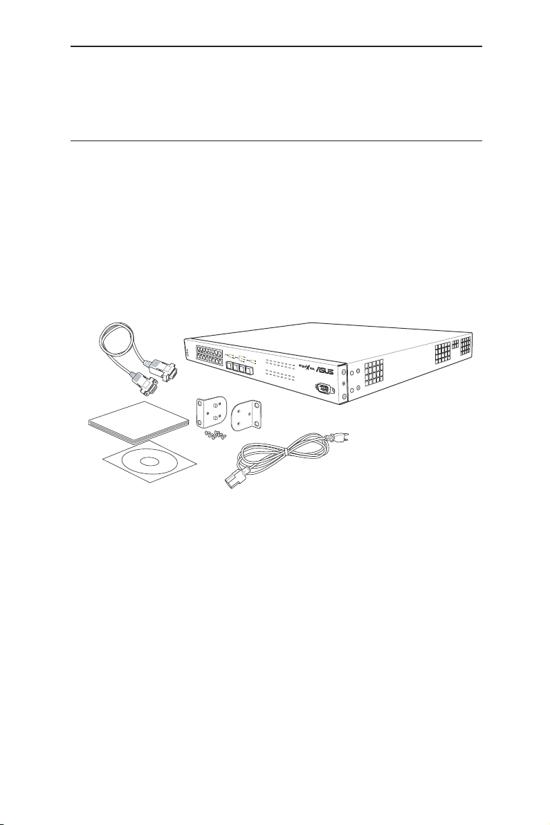
2.1 Package contents
The GigaX1116i+/ GigaX1124i+ switch package comes with the following items:
• GigaX1116i+ (16-port), or GigaX1124i+ (24-port) L2 smart plus switch
• AC Power cord
• Null modem cable for console interface (DB9)
• Rack installation kit (two brackets with six #6-32 screws)
• CD manual
• Quick installation guide
Figure 1. GigaX1116i+/ GigaX1124i+ smart switch package contents
3
Page 12
GigaX Series L2 Smart Plus Switch User Manual
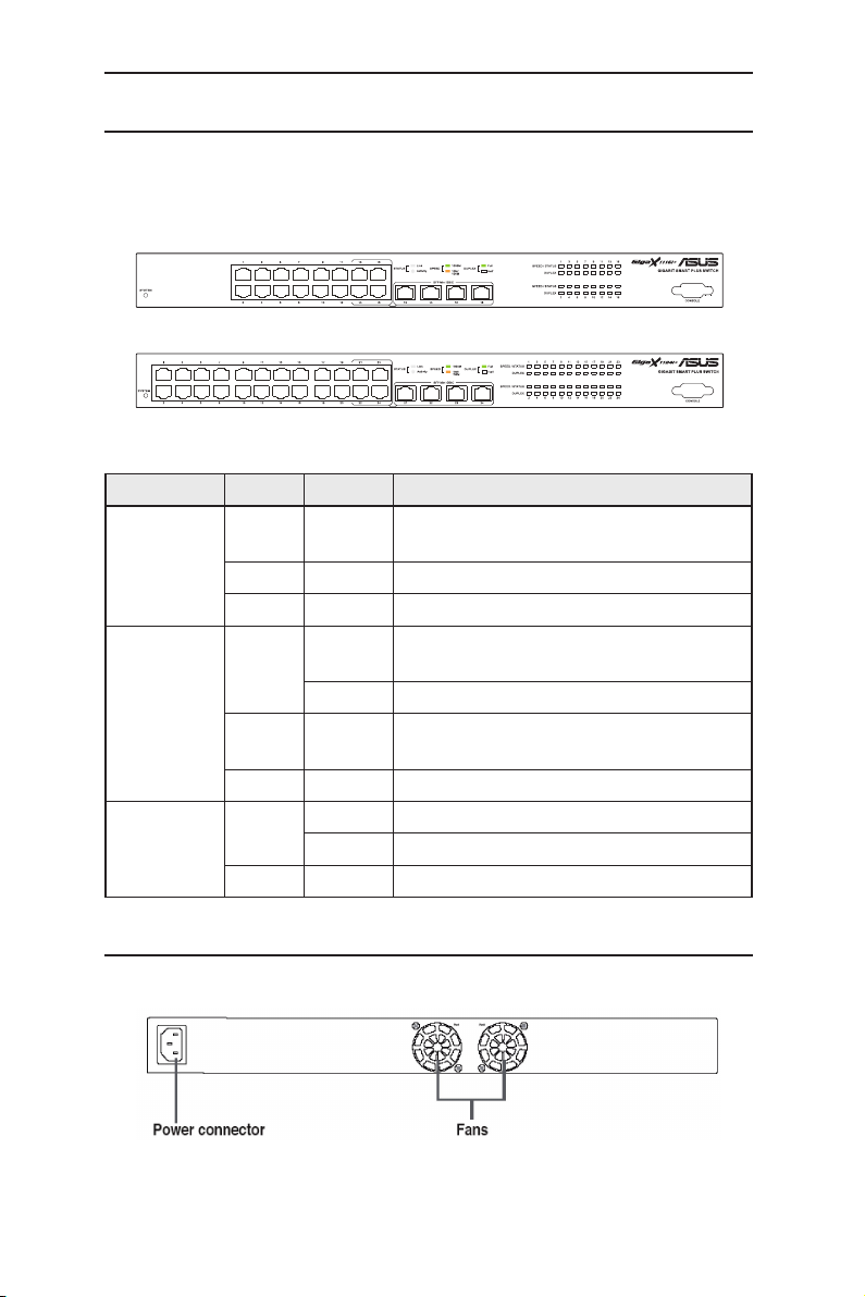
2.2 Front Panel
The front panel includes LED indicators that show the system, RPS, fan, and
port status.
GigaX 1116i+:
GigaX 1124i+:
Table 1. Front panel labels and LEDs
Label Color Status Description
SYSTEM Green ON The s witch i s power-up and oper ati ng
normally
Amber ON Abnormal temperature or voltage
OFF No power
10/100/1000
po r t sp ee d
and status
10/100/1000
port duplex
Green ON Link (RJ-45 or SFP) is present; port is
enabled ,port speed is 1000Mbps
Flashing Data is being transmitted/received
Amber ON Link (RJ-45 or SFP) is present; port is
enabled ,port speed is 100/10Mbps
OFF No Ethernet link
Green ON Full duplex
Flashing collision happens
OFF Half duplex
2.3 Rear Panel
The switch rear panel contains the fans and a power connector.
Figure 2. Rear panel
4
Page 13
GigaX Series L2 Smart Plus Switch User Manual
Table 2. Rear panel labels
No. Label Description
1 Power Connector Connects to the supplied power cord
2 FAN System fan
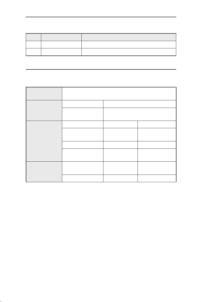
2.4 Technical specifications
Table 3. Technical specifications
Physical
Dimensions
Power
Environmental
Ranges
System Fan
43.5mm(H) x 444mm(W) x 265mm(D)
Input Consumption
100-240V AC/2.5A
50-60Hz
Operating Storage
Temperature
Humidity 15 to 90% 0 to 95%
Altitude
Dimensions
40 x 40 x 20 mm 12V DC/0.13A 8200RPM
-10 to 50°C (14
to 122°F)
up to 10,000ft
(3,000m)
Voltage and
Current
<90 watts
-40 to 70°C(-40 to
158°F)
40,000ft (12,000m)
Speed
5
Page 14

GigaX Series L2 Smart Plus Switch User Manual
3 Quick start guide
This se ction provides the basic instructions to set u p the GigaX1116i+/
GigaX1124i+ environment. Refer also to the GigaX1116 i+/ Giga X1124i+
Installation Guide.
Part 1 shows you how to install the switch on a flat surface or on a rack.
Part 2 provides instructions to set up the hardware.
Part 3 shows you how to configure basic settings on the switch.
Obtain the following i nform ation from your netw ork admini strat or be fore
proceeding:
IP address for the switch
Default gateway for the network
Network mask for this network
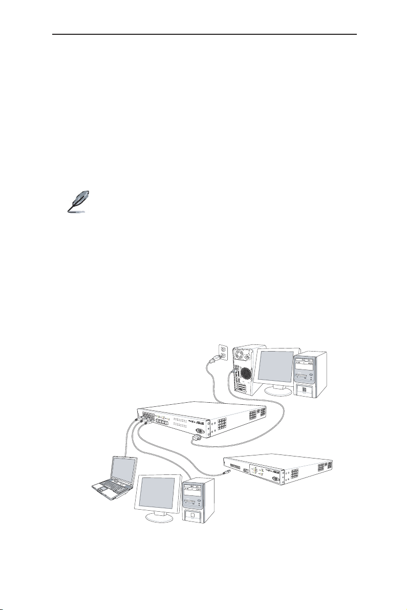
3.1 Part 1 — Installing the hardware
Connect the device to the power outlet, and your computer or network.
Figure 5 illustrates the hardware connections.
3.1.1 Installing the switch on a flat surface
The switch should be installed on a level surface that can support the weight
of the switches and their accessories. Attach four rubber pads on the marked
location on the bottom of the switch.
3.1.2 Mounting the switch on a rack
1. Attach brackets to each side of the switch and make the posts insert to the
switch.
2. Insert and tighten two screws to securely attach the bracket to the rack on
each side.
3.2 Part 2 — Setting up the switch
Connect the device to the power outlet, and your computer or network. See
Figure 5.
6
Page 15
GigaX Series L2 Smart Plus Switch User Manual
S
Y
S
T
E
M
R
P
S
F
A
N
C
O
N
S
O
L
E
R
S
2
3
2
8
4
2
1
7
5
3
6
8
4
2
1
7
5
3
6
S
Expansion Switch/Hub
Client
Client
Cat 5 (or better)
Network Cables
AC Power
RS232
Console
(RS232)
GigaX1116i+
S
Y
S
T
E
M
R
P
S
F
A
N
C
O
N
S
O
L
E
R
S
2
3
2
8
4
2
1
7
5
3
6
3.2.1 Connect the console port
For console management, use an RS232 (DB9) to connect the switch. If you
want to use WEB interface, connect your PC to the switch using the Ethernet
cable.
3.2.2 Connect to the computers or a LAN
You can use Ethernet cable to connect computers directly to the switch ports.
You can also connect hubs/switches to the switch ports by Ethernet cables.
You can use either the crossover or straight-through Ethernet cable to connect
computers, hubs, or switches.
Use a twisted-pair Category 5 Ethernet cable to connect the
1000BASE-T port. Otherwise, the link speed cannot reach
1Gbps.
3.2.3 Attach the power adapter
1. Connect the AC power cord to the POWER receptacle on the back of the
switch and plug the other end of the power cord into a wall outlet or a power
strip.
2. Check the front LED indicators with the description in Table 4. If the LEDs
light up as described, the switch hardware is working properly.
Figure 3. Overview of Hardware Connections
7
Page 16

GigaX Series L2 Smart Plus Switch User Manual
Table 4. LED Indicators
No. LED Description
Solid green indicates that the device is turned
1 SYSTEM
Switch ports
2
[1] to [16] (GigaX1116i+)
[1] to [24] (GigaX1124i+)
on. If this light is off, make sure the power cord is
attached to the Switch and plugged into a power
source.
Soli d green indicates that the device can
communicate with the LAN, or flashing when
the device is sending or receiving data from
your LAN computer.
3.3 Part 3 — Basic switch setting for management
After completing the hardware connections, configure the basic settings for your
switch. You can manage the switch using the following methods:
• Web interface: the switch has a set of pages to allow to you manage it using
Java®-enabled IE5.0 or higher version.
• Command Line Interface: use console port to manage the switch.
3.3.1 Setting up through the console port
1. Use the supplied crossover RS-232 cable to connect to the console port on
the front of the switch. This port is a male DB-9 connector, implemented as a
data terminal equipment (DTE) connection. Tighten the retaining screws on
the cable to secure it on the connector. Connect the other end of the cable
to a PC running terminal emulation software. e.g Hyper Terminal.
2. Make sure the settings of your terminal emulation software as follows:
a) Choose the appropriate serial port number
b) Set the data baud rate to 115200
c) Set the data format to no parity, 8 data bits and 1 stop bit
d) No flow control
3.3.2 Setting up through the Web interface
To successfully connect your PC to the switch, your PC must a valid IP in your
network. Contact your network administrator to obtain a valid IP for the switch.
If you wish to set up the IP address of the switch, follow section 4.3.1 to change
the IP address. Since the switch does not support DHCP client function, a valid
static IP for the switch is necessary to use Web interface.
8
Page 17
GigaX Series L2 Smart Plus Switch User Manual
1. At any PC connected to the network that the switch can access , open your
Web browser (Internet Explorer), and type the following URL in the address/
location box, and press <Enter>:
http://192.168.1.1
This is the factory default IP address of the switch.
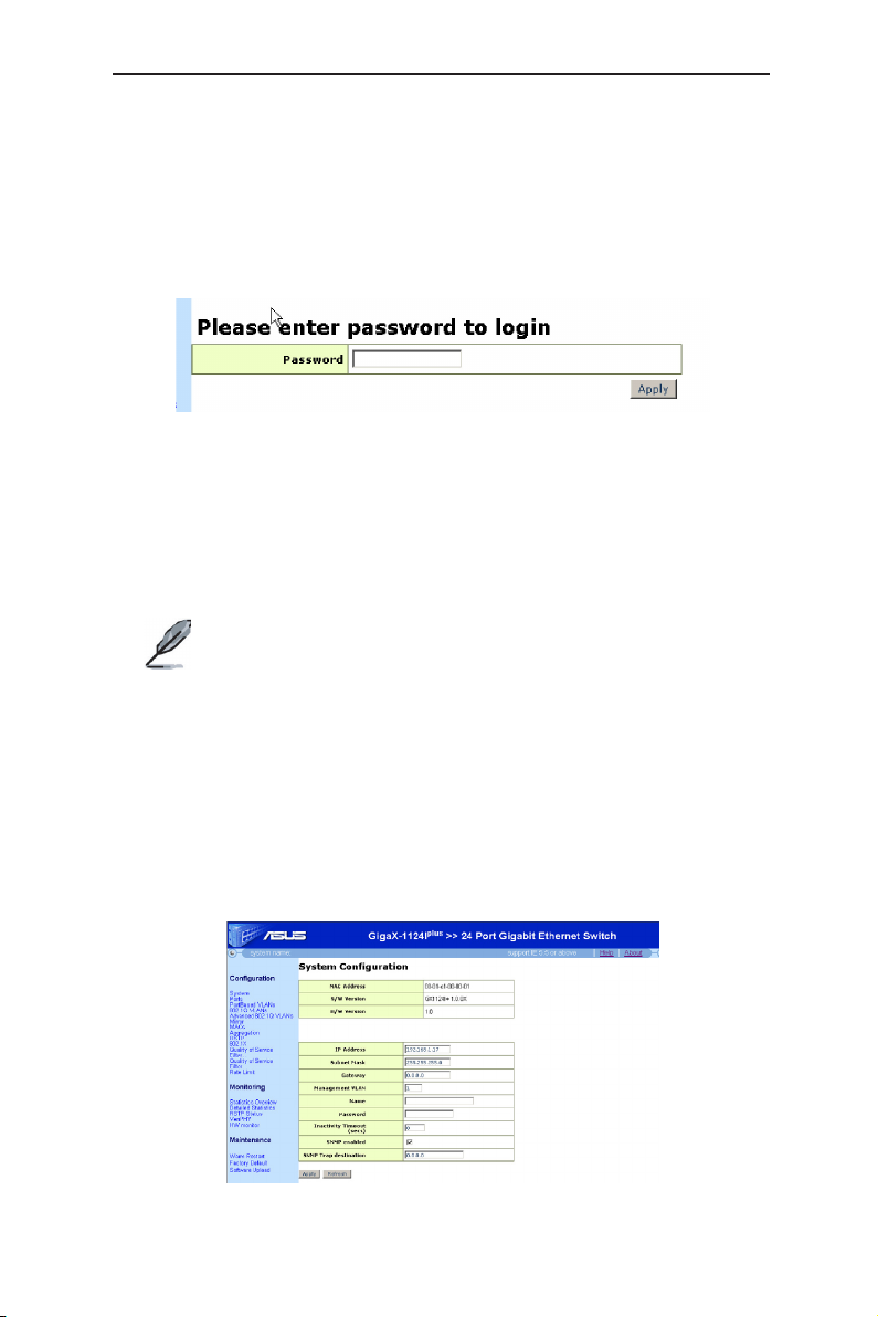
A login screen appears, as shown in Figure 4.
Figure 4. Login Screen
Enter your password or leave it blank, and then click
Manager. Use the following defaults the first time you log into this interface:
Default Password: (no password)
Default password is no password. No password means “accept all” and “disable
web login password”.
to enter the Configuration
Apply
You can change the password at any time. If you forgot the
password, the super password is “asus2357”. Super password
can only be used in console mode. After login to console, refer to
section 5.2.1 to restore factory default or to section 5.2.2 to set
new password
2. To setup a new IP address, click “System”, (see Figure 5). Fill in the IP
address, network mask and default gateway, then click
3. If your new address is different from the default, the browser cannot update
the switch status window or retrieve any page. This is normal. You have to
retype the new IP address in the address/location box, and press <Enter>.
The WEB link returns.
Apply
.
Figure 5. IP Setup
9
Page 18
GigaX Series L2 Smart Plus Switch User Manual
4 Management with the Web Interface
The switch provides Web pages that allow switch management through the
Internet. The program is designed to work best with Microsoft Internet Explorer®
5.5, or later versions. NOTE: Netscape is not supported.
The following sections show only one screen image (GigaX1124i+ model) since
GigaX1116i+ and GigaX1124i+ have the same configuration mechanism.
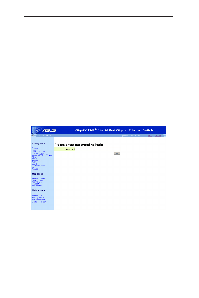
4.1 Log into Web user interface
1. From a PC, open your web browser, type the following in the web address (or
location) box, and press <Enter>:
http://192.168.1.1
This is the factory default IP address for the switch. A login screen displays,
as shown in Figure 6.
Figure 6. Configuration manager login screen
2. Enter your password, then click
Default Password: <no password>
The home page appears each time you log into the program. See Figure 7
10
Apply
.
Page 19
GigaX Series L2 Smart Plus Switch User Manual
Figure 7. Home page
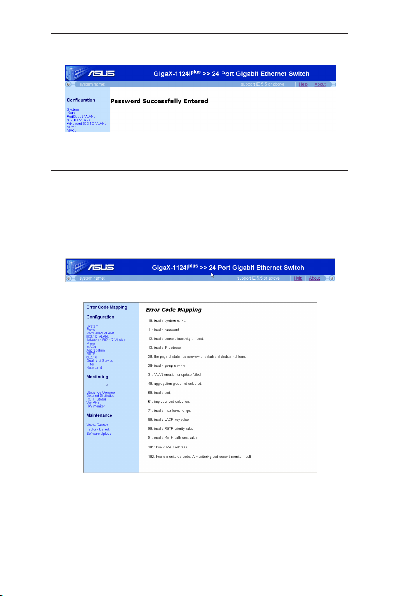
4.2 Functional layout
Typical web page consists of three separate frames, top frame, menu frame,
main frame. The top frame as shown in Figure 8 has a switch logo, help and
about page. Click on the Help. The help window is shown as Figure 9. The error
codes in the web page are listed. Click the item in the left menu, the individual
help page for this item will be shown. The about page will lead you to the ASUS
official Web site http://www.asus.com
Figure 8. Top frame
Figure 9. Help Page
11
Page 20
GigaX Series L2 Smart Plus Switch User Manual
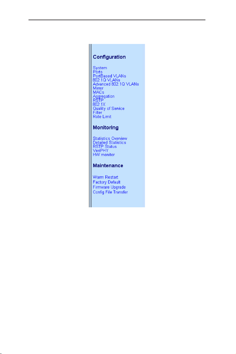
The left frame, a menu frame as shown in Figure 10, contains all the features
available for switch configuration.
Figure 10. Expanded Menu List
The right frame displays configuration pages or graphics for the statistics. See
section 4.3 for details.
4.2.1 Commonly used buttons and icons
The following table describes the function for each button and icon used in the
application.
12
Page 21
GigaX Series L2 Smart Plus Switch User Manual
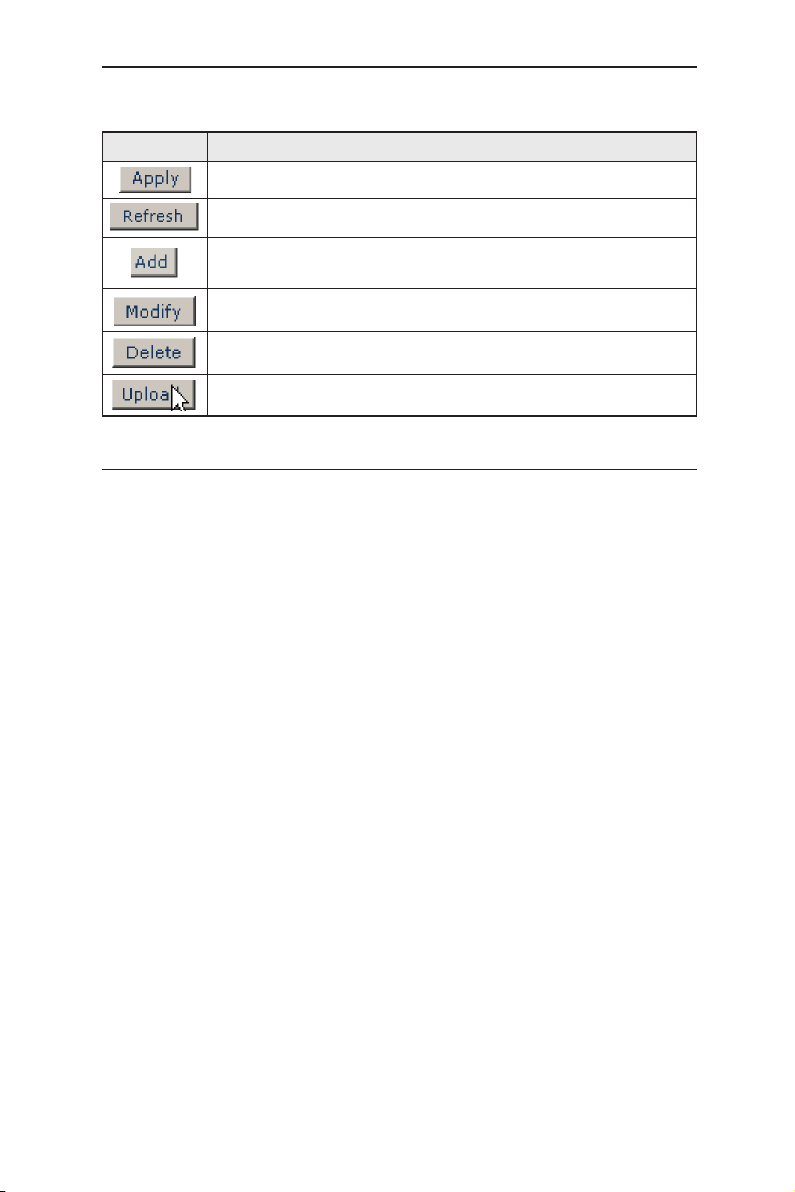
Table 5. Commonly used buttons and icons
Button/Icon Function
Stores any changes you have made on the current page.
Re-displays the current page with updated statistics or settings.
Adds the existing configuration to the system, e.g. portBased
VLAN, 802.1Q VLAN, MAC address ,etc.
Modifies an existing entry
Deletes the selected item, e.g. a VLAN, MAC address, etc.
Re-displays the current page with updated statistics or settings.
4.3 Configuration Pages
Configuration pages include System, Ports, PortBased VLANs, 802.1Q VLANs,
Advanced 802.1Q VLANs, Mirror, MACs, Aggregation, RSTP, 802.1X, Quality of
Service, Filter, Rate limit.
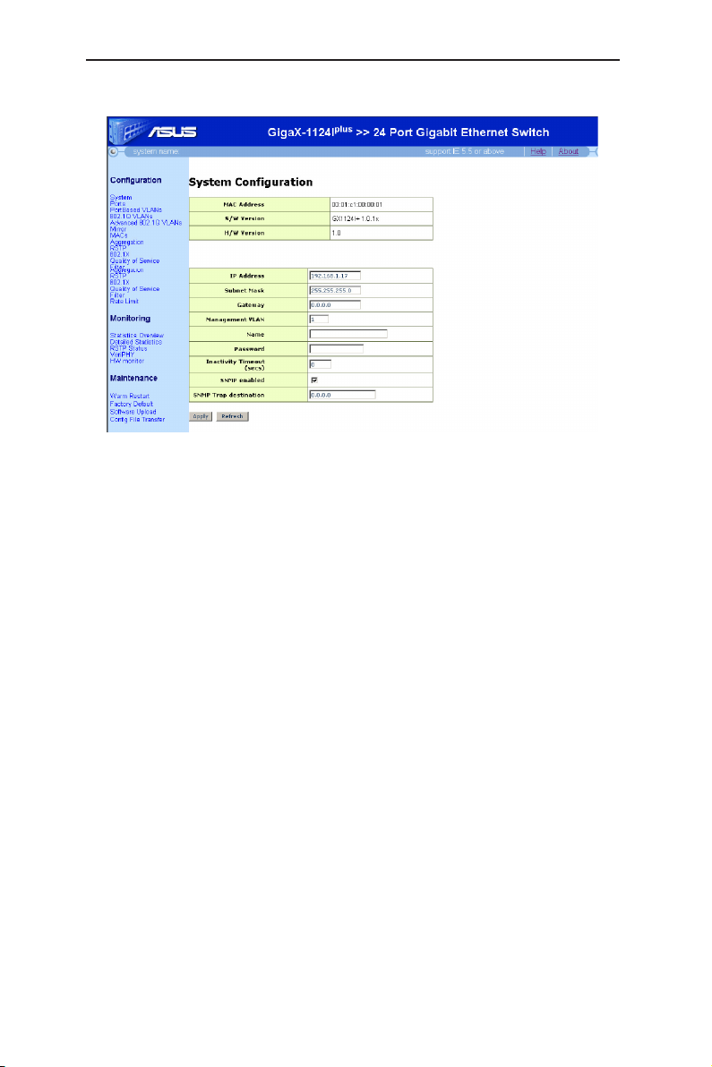
4.3.1 System
The System page contains the following information:
• IP Address: Setup or show IP configuration.
• Subnet Mask: Setup or show Subnet Mask.
• Gateway: Setup or show Gateway.
• Management VLAN: Setup or show Management VLAN(1-4095).
• Name: Setup or show system name.
• Password: Setup password. The empty string ("") disables the password
check. Only perform a factory default can set password blank.
• Inactivity Timeout (secs): Set or show the console inactivity timeout in
seconds. The range is 60-10000. The value zero disables timeout.
• SNMP enable: Check box for enable. Default Read Community name is
"public" and Write (Set) community name must be the same as the system
password.
• SNMP trap destination: Set or show the IP address SNMP trap sent to.
Click on the
button to refresh the setting to current value. as shown in Figure 11.
button to make the configuration effective, or the
Apply
Refresh
13
Page 22
GigaX Series L2 Smart Plus Switch User Manual
Figure 11. System Configuration
4.3.2 Ports
On this page, users know the ethernet port status in real time. On the other
hand, users can configure the port in the following fields:
On this page, users know the ethernet port status in real time. On the other
hand, users can configure the port in the following fields:
• Link: Show link up status or link down.
• Mode: Set or show the speed and duplex mode.
• Flow Control: Enable/disable 802.3x flow control mechanism.
• Max Frame: Set or show the maximum frame size in bytes (including FCS)
for frames received on the port. Tagged frames are allowed to be 4 bytes
longer than the maximum frame size. The range of valid maximum frame
size is between 1518 and 9600.
• Trunk: Show trunk information. Be sure the port attribute of the Trunk
member should be the same in the trunk group.
Click on the
button to refresh the setting to current value as shown in Figure 12.
button to make the configuration effective, or the
Apply
Refresh
14
Page 23

GigaX Series L2 Smart Plus Switch User Manual
Figure 12. Port Configuration
4.3.3 Port-Based VLAN Configuration
Port-Based VLANs provide another way than VLAN for making port grouping.
With port-based VLAN, it is possible to share a port between more groups.
Users can configure the group in the following ways:
• Add a new group: Fill in the new group ID and then click on the “Add” button.
On the next page, select the ports or trunks that need to be assigned to this
group. Click on the “Apply” button to make the configuration effective, or the
“Refresh” button to refresh the setting to current value.
• Modify a group: Select the group that needs to be modified and then click
on the “Modify” button. On the next page, select the ports or trunks that
need to be assigned to this group. Click on the “Apply” button to make
the configuration effective, or the “Refresh” button to refresh the setting to
current value.
15
Page 24

GigaX Series L2 Smart Plus Switch User Manual
• Delete a group: Select the group that needs to be deleted and then click on
the “Delete” button.
Click on the
button to make the configuration effective, or the
Apply
Refresh
button to refresh the setting to current value as shown in Figure 14.
Figure 13. Port-Based VLAN
16
Figure 14. Add a Port-Based VLAN group
Page 25

GigaX Series L2 Smart Plus Switch User Manual
4.3.4 802.1Q VLANs Configuration
There are up to 16 VLAN groups to be configured. Users can configure the
group in the following ways:
• Add a new VLAN: Fill in the new VLAN ID and then click on the “Add” button.
On the next page, select the ports or trunks that need to be assigned to this
VLAN. Click on the “Apply” button to make the configuration effective, or the
“Refresh” button to refresh the setting to current value.
• Modify a VLAN: Select the VLAN that needs to be modified and then click
on the “Modify” button. On the next page, select the ports or trunks that
need to be assigned to this VLAN. Click on the “Apply” button to make
the configuration effective, or the “Refresh” button to refresh the setting to
current value.
• Delete a VLAN: Select the VLAN that needs to be deleted and then click on
the “Delete” button.
Click on the
button to refresh the setting to current value as shown in Figure 15. Next page is
shown in Figure 16.
button to make the configuration effective, or the
Apply
Refresh
Figure 15. 802.1Q VLAN
17
Page 26

GigaX Series L2 Smart Plus Switch User Manual
Figure 16. Add a 802.1Q VLAN
4.3.5 Advanced 802.1Q VLAN
Users can configure the advanced attributes of each port related to 802.1Q
VLAN in the following fields:
• Aware--
Ingress: Keep tag value for tagged packets received. For untagged packets
received, insert tag with PVID on the incoming packets.
Egress: Compare egress port PVID with the tag value of outgoing packets. If
the same, remove the tag. If not the same, keep the tag.
Unaware--
Ingress - Always insert tag with PVID for incoming packets.
Egress - Always remove the tag for outgoing packets.
• Member Check: If enabled, the system will discard incoming frames for
VLANs which do not include this port in its member set.
• Accept Frame Type: Accept all frames (tagged or untagged) or tagged
frames only.
• PVID: Set or show the port VLAN ID. Untagged frames received on the port
will be classified to this VLAN ID. Frames classified to this VLAN ID will be
sent untagged on the port.
Click on the
button to refresh the setting to current value as shown in Figure 17.
button to make the configuration effective, or the
Apply
Refresh
18
Page 27

GigaX Series L2 Smart Plus Switch User Manual
Figure 17. Advanced 802.1Q VLANs
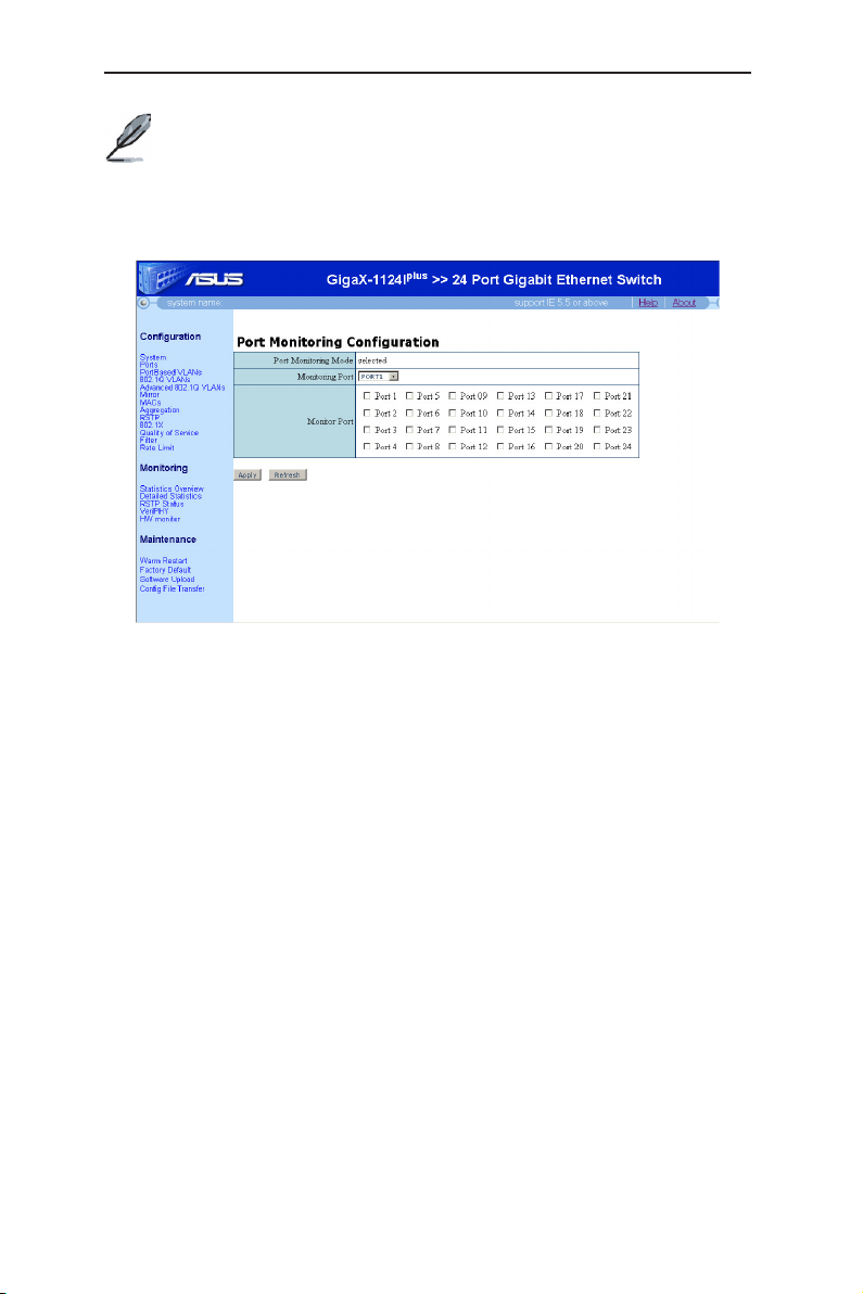
4.3.6 Mirror
Users can enable mirroring of frames received on selected ports by configuring
the monitored and monitoring ports in the following fields:
• Monitoring Port: Receive the copies of all the traffics in the selected mirrored port.
• Monitored Port: Select the ingress ports being mirrored.
Click on the
button to refresh the setting to current value as shown in Figure 18.
button to make the configuration effective, or the
Apply
Refresh
19
Page 28
GigaX Series L2 Smart Plus Switch User Manual
The monitor port cannot belong to any link aggregation group.
The monitor port cannot operate as a normal switch port. It does
not switch packets or do address learning.
If there is no monitored port selected, it means the function port
mirroring is disabled.
Figure 18. Mirror Configuration
4.3.7 MACs
Configure or show the permanently stored MAC table. Users can configure the
MAC entry in the following ways:
• Add a new MAC entry: Fill in the VLAN ID and MAC address. Then click
on the “Add” button. On the next page, select the ports that belong to this
entry. Click on the “Apply” button to make the configuration effective, or the
“Refresh” button to refresh the setting to current value.
• Modify a MAC entry: Select the entry that needs to be modified and then
click on the “Modify” button. On the next page, select the ports that belong to
this group. Click on the “Apply” button to make the configuration effective, or
the “Refresh” button to refresh the setting to current value.
• Delete a MAC entry: Select the entry that needs to be deleted and then click
on the “Delete” button.
Click on the
button to refresh the setting to current value as shown in Figure 19. Next page is
shown in Figure 20.
20
button to make the configuration effective, or the
Apply
Refresh
Page 29

GigaX Series L2 Smart Plus Switch User Manual
Figure 19. MAC Address Configuration
Figure 20. Add/Modify a MAC Address Entry
21
Page 30

GigaX Series L2 Smart Plus Switch User Manual
4.3.8 Aggregation
Configure or show the aggregation groups. Users can selcect the group
members in each aggregation group.
Click on the
button to refresh the setting to current value as shown in Figure 21.
If all the trunk members are in the same speed and full duplex mode, then the
trunk group is set up successfully. If one of the members is not in the same
speed or full duplex mode, the trunk is not set correctly. Check the link partner
and change the settings to have the same speed and full duplex mode for all the
members of your trunk group.
• All the ports in the link aggregation group MUST operate in full-duplex mode
at the same speed.
• All the ports in the link aggregation group MUST be configured in autonegotiation mode or full duplex mode. This configuration will make the full
duplex link possible. If you set the ports in full duplex force mode, then the
link partner MUST have the same setting. Otherwise the link aggregation
could operate abnormally.
• All the ports in the link aggregation group MUST have the same VLAN setting.
• All the ports in the link aggregation group are treated as a single logical
link. That is, if any member changes an attribute, the others will change too.
For example, a trunk group consists of port 1 and 2. If the VLAN of port 1
changes, the VLAN of port 2 also changes with port 1.
button to make the configuration effective, or the
Apply
Refresh
22
Figure 21. Aggregation Configuration
Page 31

GigaX Series L2 Smart Plus Switch User Manual
4.3.9 RSTP
Users can change the RSTP system configuration in the following fields:
• System Priority: Set or show the RSTP System Priority. Number between 0
- 61440 in increments of 4096. This provides for 16 distinct values: 0, 4096,
8192, 12288, 16384, 20480, 24576, 28672, 32768, 36864, 40960, 45056,
49152, 53248, 57344 and 61440.
• Hello Time: Set or show the RSTP System Hello time. Number is between 1
- 10 (default is 2).
• Max Age: Set or show the RSTP System Max Age. Number is between 6 40 (default is 20).
• Forward Delay: Set or show the RSTP System Forward delay. Number is
between 4 - 30 (default is 15).
• Force Version: Set or show the RSTP protocol version to use.
Normal - It will try to send out RSTP packets first. If there is no RSTP
devices in its neighbourhood, it will try to send out STP packets instead;
Compatible - It will send out STP packets only.
Users can change the RSTP port configuration in the following field:
• Protocol Enabled: Enable or disable the RSTP protocol on the port or
aggregation links.
• Edge: Enable to expect the port to be an edge port (an end station) or
disable to make the port have a link to another STP device (bridge).
• Path Cost: Set the RSTP pathcost on the port. Number is between 1 -
200000000. Auto means autogenerated pathcost.
Click on the
button to refresh the setting to current value as shown in Figure 22.
button to make the configuration effective, or the
Apply
Refresh
23
Page 32

GigaX Series L2 Smart Plus Switch User Manual
24
Figure 22. RSTP Configuration
Page 33

GigaX Series L2 Smart Plus Switch User Manual
4.3.10 802.1X
Users can change the 802.1X configuration in the following fields:
• Mode: Enable or disable 802.1X process for the switch.
• RADIUS IP: Set or show RADIUS server IP address.
• RADIUS UDP Port: Set up UDP Port for the external RADIUS server.
• RADIUS Secret: Set or show the secret shared with the RADIUS server.
• Admin State: Set or show the configured 802.1X state for the port.
Auto: Behavior of the port is controlled by 802.1X protocol.
Force Authorized: Traffic from all hosts to the port is allowed to pass.
Force Unauthorized: Port is blocked and no traffic can go through.
• Port State: Show the port real-time state. (802.1X Disabled, Link Down,
Unauthorized, or Authorized)
• Re-authenticate: Refresh (restart) 802.1X authentication process for the
port.
• Force Reinitialize: Reinitialize the port.
• Statistics: Click to show the Authenticator counters, Backend Authenticator
counters, dot1x MIB counters, and Last Supplicant identity of the port.
• Re-authenticate All: Refresh (restart) 802.1X authentication process for all
ports.
• Force Reinitialize All: Reinitialize all ports.
Click on the “Parameters” button to change 802.1X parametes in the following
field:
• Reauthentication Enabled : E nable or disable reauthentication. Once
enabled, the switch will try to authenticate the port user again in a predefined
period.
• Reauthentication Period: If reauthentication is enabled, this is the time
period to re-send authentication request to the port user. Number is between
1 - 3600.
• EAP timeout: Number is between 1 - 255.
Click on the
button to refresh the setting to current value as shown in Figure 23. The next
page for statistics is shown in Figure 24. The third page for parameter is shown
in Figure 25.
button to make the configuration effective, or the
Apply
Refresh
25
Page 34

GigaX Series L2 Smart Plus Switch User Manual
26
Figure 23. 802.1X Configuration
Figure 24. 802.1X Statistics
Page 35

GigaX Series L2 Smart Plus Switch User Manual
Figure 25. 802.1X Parameter
4.3.11 Quality of Service
Users can change the QoS configuration in the following fields:
• Mode: Set or show the QoS mode for the port. In Tag mode, it will retrieve
the priority in tagged packet as the priority. It will use the user priority for
untagged packet. In Port mode, it will use default priority (class) for tagged
and untagged packet.
• Port Priority: Set or show the default VLAN user priority of the port for
untagged frames.
Click on the
button to refresh the setting to current value.
Click on the
following field:
• Class: The switch supports 4 classes for each port. Select the class that the
priority maps into.
Click on the
button to refresh the setting to current value as shown in Figure 26. Next page
for Priority Mapping is shown in Figure 27.
button to make the configuration effective, or the
Apply
Priority Mapping
button to make the configuration effective, or the
Apply
button to change QoS priority mapping in the
Refresh
Refresh
27
Page 36

GigaX Series L2 Smart Plus Switch User Manual
Figure 26. QoS Configuration
28
Figure 27. QoS Priority Mapping
Page 37

GigaX Series L2 Smart Plus Switch User Manual
4.3.12 Filter
The function filters source IP only. Users can change the source IP filter
configuration in the following fields:
• Mode: Select “Disabled” to allow all IP addresses. Select “Manually” to allow
only the configured IP addresses.
• IP Address and IP Mask: When “Manually” mode is selected, these are the
IP addresses allowed.
Click on the
button to refresh the setting to current value as shown in Figure 28.
button to make the configuration effective, or the
Apply
Refresh
Figure 28. Filter Configuration
29
Page 38

GigaX Series L2 Smart Plus Switch User Manual
4.3.13 Rate Limit
Users can change the rate limit configuration in the following fields:
• ICMP Rate: Select the limited rate of ICMP frames.
• Broadcast Rate: Select the limited rate of broadcast frames.
• Multicast Rate: Select the limited rate of multicast frames.
• Flooded Unicast Rate: Select the limited rate of flooded unicast frames.
• Policer: Control maximum ingress bandwidth rate.
• Shaper: Control maximum egress bandwidth rate.
Click on the
button to refresh the setting to current value as shown in Figure 29.
button to make the configuration effective, or the
Apply
Refresh
30
Figure 29. Rate Limit Configuration
Page 39

GigaX Series L2 Smart Plus Switch User Manual
4.4 Monitoring
The Monitoring page group contains Statistics Overview, Detail Statistics, RSTP
Status, VeriPHY, HW Monitor.
4.4.1 Statistics Overview
This page shows Tx Bytes, Tx Frames, Rx Bytes, Rx Frames, Tx Errors, and Rx
Errors of each port. Show Trunk: Select “Add a new Trunk” for a new created
group. Or select an existed group to display on the following fields and port
icons.
Click on the
button to refresh the setting to current value as shown in Figure 30.
button to make the configuration effective, or the
Apply
Refresh
Figure 30. Statistics Overview
4.4.2 Detailed Statistics
This page shows Receive Total, Transmit Total, Receive Size Counters, Transmit
Size Counters, Receive Error Counters, and Transmit Error Counters of each
port.
Click on the Port number on the top of the page to see the statistics of that port.
Click on the
button to refresh the setting to current value as shown in Figure 31.
button to make the configuration effective, or the
Apply
Refresh
31
Page 40

GigaX Series L2 Smart Plus Switch User Manual
Figure 31. Detailed Statistics
4.4.3 RSTP Status
This page shows RSTP VLAN bridge overview and RSTP port status
Click on the
Figure 32.
Refresh
button to refresh the setting to current value as shown in
Figure 32. RSTP Status
32
Page 41

GigaX Series L2 Smart Plus Switch User Manual
4.4.4 VeriPHy
Users can perform cable diagnostics by determining the parameters in the
following fields:
• Port: Select the port to be performed cable diagnostics.
• Mode: Type of diagnostics, default is
full anomaly check.
without X-pair
between pairs.
Click on the
button to refresh the setting to current value as shown in Figure 33.
Apply
Anomaly
comprises anomaly check without check for coupling
button to make the configuration effective, or the
Full. Full
comprises full anomaly check.
comprises cable length and
Anomaly
Refresh
Figure 33. VeryPHY
4.4.5 HW Monitor
This page shows the temperature, fan speed and voltage of hardware, as shown
in Figure 34.
Figure 34. HW Monitor
33
Page 42

GigaX Series L2 Smart Plus Switch User Manual
4.5 Maintenance
The Maintenance page group contains Warm Restart, Factory Default, Software
Upload and Config file transfer.
4.5.1 Warm Restart
• Click on the
button to perform a warm restart as shown in Figure 35.
Yes
Figure 35. Warm Restart
4.5.2 Factory Default
IP will be reset to 192.168.1.1.
Click on the
button to perform factory default as shown in Figure 36.
Yes
Figure 36. Factory Default
4.5.3 Firmware Upgrade
Use the function to update the current firmware version. Select the firmware file
and click on the
34
button to upload the firmware as shown in Figure 37.
Upload
Figure 37. Firmware Upload
Page 43

GigaX Series L2 Smart Plus Switch User Manual
4.5.4 Config File Transfer
Backup and restore the configuration file. Click on the
collect the current configuration as a configuration file to local disk or select a
configuration file from local disk and click on the
configuration file as shown in Figure 38.
Download
button to restore the
Upload
button to
Figure 38. Config file Transfer
35
Page 44

GigaX Series L2 Smart Plus Switch User Manual
5 Console Interface
This chapter describes how to use console interface to configure the switch. The
switch provides RS232 connectors to connect your PC. Use a terminal emulator
on your PC such as HyperTerminal and command line interpreter to configure
the switch. You have to set up the terminal emulator with baud rate 115200, 8 bit
data, no parity, and 1 stop bit, and no flow control.
Once you enter CLI mode, type “?” will display all available command help
messages. The “?” is valid for the root and sub-directory command tree. This is
very useful when you are not familiar with the CLI commands.
In order to make them easier to use, you can enter into different category by
typing the full command, then this category becomes your working category.
Thereafter, you donʼt have to type “system” before any sub-commands. For
example, “system” is a command category including a lot of sub-commands.
You donʼt have to type “system” for the sub-commands once you change your
working category to “sys” by typing “sys”. The prompt will become “system>”
when your working category is “sys”.
5.1 Password
After rebooting, you need to type password to enter the CLI mode. The default
password is no password.
5.2 CLI Commands
The switch provides CLI commands for all managed functions.
Always use “?” to get the available commands list and help. Put
“?” after the CLI commands to get the help.
Always use “/” to get back to the root directory.
5.2.1 System Commands
[System Configuration ]
Show system name, software version, hardware version and management MAC
address. Optionally show the full configuration
[all]: Show the total switch configuration (default: System configuration only)
CLI command : System Configuration [all]
If you put a name in the name description field, the switch system name changes
to the new one.
36
Page 45

GigaX Series L2 Smart Plus Switch User Manual
[System Restore Default]
Restore factory default configuration.
[keepIP]: Preserve IP configuration (default: Not preserved).
CLI command : System Restore Default [keepIP]
[System Name]
Set or show the system name.
[<name>]: String of up to 16 characters (default: Show system name).
CLI command : System Name [<name>]
[System Reboot]
Reboot the switch.
[<name>]: String of up to 16 characters (default: Show system name).
CLI command : System Reboot
[System SNMP]
Activate or deactivate the SNMP.
[enable|disable]: Enable/disable SNMP (default: Show SNMP mode).
CLI command : System SNMP [enable|disable]
[System Trap]
Set or show SNMP traps destination.
<IP Address>: IP address to send traps to. (default: Show trap configuration)
CLI command : System Trap [<IP Address>]
5.2.2 Console Commands
[Console Configuration]
Show configured console password and timeout.
CLI command : Console Configuration
37
Page 46

GigaX Series L2 Smart Plus Switch User Manual
[Console Password]
Set or show the console password. The empty string (“”) disables the password
check.
[<password>]: Password string of up to 16 characters..
CLI command : Console Password [<password>]
[Console Timeout]
Set or show the console inactivity timeout in seconds. The value zero
disables timeout.
[<timeout>]: Timeout value in seconds, 0,60-10000.
CLI command : Console Timeout [<timeout>]
[Console Prompt]
Set or show the console prompt string.
[<prompt_string>]: Command prompt string of up to 10 characters.
CLI command : Console Prompt [<prompt_string>]
5.2.3 Port Commands
[Port Configuration]
Show the configured and current speed, duplex mode, flow control
mode and state for the port.
[<portlist>]: Port list (Default: All ports).
CLI command : Port Configuration [<portlist>]
[Port Mode]
Set or show the speed and duplex mode for the port.
[<portlist>]: Port list (Default: All ports).
[<mode>]: Port speed and duplex mode (Default: Show configured and current
mode).
10hdx : 10 Mbit/s, half duplex.
10fdx : 10 Mbit/s, full duplex.
100hdx : 100 Mbit/s, half duplex.
38
Page 47

GigaX Series L2 Smart Plus Switch User Manual
100fdx : 100 Mbit/s, full duplex.
1000fdx: 1 Gbit/s, full duplex.
auto : Auto negotiation of speed and duplex.
CLI command : Port Mode [<portlist>] [<mode>]
[Port Flow Control]
Set or show flow control mode for the port.
[<portlist>] : Port list (default: All ports).
[enable|disable]: Enable/disable flow control (default: Show flow control
mode).
CLI command : Port Flow Control [<portlist>] [enable|disable]
[Port State ]
Set or show the state for the port.
[<portlist>] : Port list (default: All ports).
[enable|disable]: Enable or disable port state (default: Show state).
CLI command : Port State [<portlist>] [enable/disable]
[Port MaxFrame]
Set or show the maximum frame size in bytes (including FCS) for frames
received on the port. Tagged frames are allowed to be 4 bytes longer than the
maximum frame size. Use the reset option to return to default setting.
[<portlist>]: Port list (default: All ports).
[<framesize>|reset]: Maximum frame size [1518-9600] or reset to 1518 bytes
(default: Show maximum frame size).
CLI command : Port MaxFrame [<portlist>] [<framesize>|reset]
[Port Statistics ]
Show or clear statistics for the port.
[<portlist>]: Port list (default: All ports).
[clear] : Clear port statistics (default: Show statistics).
CLI command : Port Statistics [<portlist>] [clear]
39
Page 48

GigaX Series L2 Smart Plus Switch User Manual
[Port Excessive Collisions Drop]
Enable or disable drop of frames when excessive collisions occur in half duplex
mode.
[enable|disable]: Enable/disable frame drop (default: Show Excessive
Collisions Drop mode)..
CLI command : Port Excessive Collisions Drop [enable|disable]
[VeriPHY]
Perform VeriPHY cable diagnostics on the specified port(s).
[<portlist>]: Port list (Default: All ports).
[full|anomaly|termination]: Type of diagnostics. Full comprises cable
length and full anomaly check, anomaly comprises full anomaly check and
termination comprises anomaly check without check for coupling between
pairs. (default: full).
CLI command : VeriPHY [<portlist>] [full|anomaly|termination]
5.2.4 MAC Commands
[MAC Configuration]
Show the permanently stored MAC table and the MAC ageing timer.
CLI command : MAC Configuration
[MAC Add]
Add permanent MAC address and VLAN ID on ports.
<macaddress>: MAC address, 12 digit hex string, optionally separated with
dashes or colons (e.g. 010203ABCDEF or 01-02-03-AB-CD-EF or 01:02:03:
AB:CD:EF).
<portlist> : Port list. Use “none” to specify no ports.
[<vid>] : VLAN ID, 1-4095 (default: 1).
CLI command : MAC Add <macaddress> <portlist>|none [<vid>]
[MAC Delete]
Delete MAC address and VLAN ID.
<macaddress>: MAC address, 12 digit hex string, optionally separated with
dashes or colons (e.g. 010203ABCDEF or 01-02-03-AB-CD-EF or 01:02:03:
AB:CD:EF).
40
Page 49

GigaX Series L2 Smart Plus Switch User Manual
[<vid>] : VLAN ID (default: All).
CLI command : MAC Delete <macaddress> [<vid>]
[MAC Lookup]
Lookup MAC address and VLAN ID.
<macaddress>: MAC address, 12 digit hex string, optionally separated with
dashes or colons (e.g. 010203ABCDEF or 01-02-03-AB-CD-EF or 01:02:03:
AB:CD:EF).
[<vid>]: VLAN ID, 1-4095 (default: 1).
CLI command : MAC Lookup <macaddress> [<vid>]
[MAC Table]
Show the MAC address table for VLAN ID list.
<vidlist> : VLAN ID list.
CLI command : MAC table <vidlist>
[MAC Flush]
Removes non-locked entries from the switch MAC table.
CLI command : MAC Flush
[MAC Agetime]
Set or show the MAC age timer in seconds. The value zero disables ageing.
[<agetime>]: Age timer in seconds, 0 or 10-65535 (default: Show timer)..
CLI command : MAC Agetime [<agetime>]
5.2.5 Vlan Commands
[VLAN Configuration]
Show the VLAN aware mode, port VLAN ID and accepted frame type for the
port and the permanently stored VLAN table.
[<portlist>]: Port list (default: All ports).
CLI command : VLAN Configuration [<portlist>]
41
Page 50

GigaX Series L2 Smart Plus Switch User Manual
[VLAN Add]
Add VLAN entry and include ports in member set.
<vidlist> : VLAN ID list.
[<portlist>]: Port list (default: All ports)..
CLI command : VLAN Add <vidlist> [<portlist>]
[VLAN Delete]
Delete VLAN entry (all ports excluded from member set).
<vidlist> : VLAN ID list.
CLI command : VLAN Delete <vidlist>
[VLAN Lookup]
Lookup VLAN entry and show port list.
<vidlist> : VLAN ID list.
CLI command : VLAN Lookup <vidlist>
[VLAN Aware]
Set or show the VLAN awareness mode for the port. VLAN aware ports will strip
the VLAN tag from received frames and insert the tag in transmitted frames
(except PVID). VLAN unaware ports will not strip the tag from received frames
or insert the tag in transmitted frames.
[<portlist>]: Port list (default: All ports).
[enable|disable]: Enable/disable VLAN awareness (default: Show
awareness).
CLI command : VLAN Aware [<portlist>] [enable|disable]
[VLAN PVID]
Set or show the port VLAN ID. Untagged frames received on the port will
be classified to this VLAN ID. Frames classified to this VLAN ID will be sent
untagged on the port.
[<portlist>]: Port list (default: All ports).
[<vid>|none]: Port VLAN ID, 1-4095 (default: Show PVID). The ʻnoneʼ option
can be used for trunk links.
CLI command : VLAN PVID [<portlist>] [<vid>|none]
42
Page 51

GigaX Series L2 Smart Plus Switch User Manual
[VLAN Frame Type]
Set or show the accepted frame type for the port.
[<portlist>]: Port list (default: All ports).
[all|tagged]: Accept all or only tagged (default: Show frame type).
CLI command : VLAN Frame Type [<portlist>] [all|tagged]t>
[VLAN Member Check]
Set or show the member check for the port.
[<portlist>]: Port list (default: All ports).
[enable|disable]: Enable or disable member check (default: Show member
check).
CLI command : VLAN Member Check [<portlist>] [enable/disable]
5.2.6 Aggr Commands
[Aggr Configuration]
Shows the aggregation groups and the aggregation mode.
CLI command : Aggr Configuration
[Aggr Add]
Add link aggregation group including ports.
<portlist>: Aggregation port list.
CLI command : Aggr Add <portlist>
[Aggr Delete]
Delete link aggregation group.
<portlist>: Port list. Aggregations including any of the ports will be deleted.
CLI command : Aggr Delete <portlist>
[Aggr Lookup]
Lookup and display link aggregation group.
<portlist>: Port list. Aggregations including any of the ports will be shown.
CLI command : Aggr Lookup <portlist>
43
Page 52

GigaX Series L2 Smart Plus Switch User Manual
[Aggr Mode]
Set or show link aggregation traffic distribution mode.
[smac|dmac|xor]: Aggregation mode, SMAC, DMAC or XOR (default: Show
mode).
CLI command : Aggr Mode [smac|dmac|xor]
5.2.7 Rstp Commands
[Rstp Configuration]
Show RSTP configuration.
[<portlist>]: Port list (Default: All ports).
CLI command : Rstp Configuration [<portlist>]
[Rstp Sysprio]
Set or show the RSTP System Priority.
[<sysprio>]: Number between 0 - 61440 in increments of 4096. This provides
for 16 distinct values: 0, 4096, 8192, 12288, 16384, 20480, 24576, 28672,
32768, 36864, 40960, 45056, 49152, 53248, 57344 and 61440.
CLI command : Rstp sysprio [<sysprio>]
[Rstp Hellotime]
Set or show the RSTP System Hello time.
[<secs>]: Number between 1 - 10 (default is 2)
CLI command : Rstp hellotime [<secs>]
[Rstp Maxage]
Set or show the RSTP System Max Age.
[<hops>]: Number between 6 - 40 (default is 20)
CLI command : Rstp maxage [<hops>]
[Rstp Fwddelay]
Set or show the RSTP System Forward delay.
[<secs>]: Number between 4 - 30 (default is 15)
CLI command : Rstp fwddelay [<secs>]
44
Page 53

GigaX Series L2 Smart Plus Switch User Manual
[Rstp Version]]
Set or show the RSTP protocol version to use.
[<version>]: normal - use RSTP, compat - compatible with old STP
CLI command : Rstp version [normal|compat]
[Rstp Mode]
Enable or disable the rstp protocol on ports <portlist>.
[<portlist>]: Port list (Default: All ports).
[enable|disable]: Enable or disable.
CLI command : Rstp Mode [<portlist>] [enable|disable]
[Rstp Aggr]
Enable or disable the RSTP protocol on aggregated links.
[enable|disable]: Enable or disable.
CLI command : Rstp aggr [enable|disable]
[Rstp Edge]
Expect the port to be an edge port (an end station) or a link to another STP device.
[enable|disable]: End-station or bridge.
CLI command : Rstp edge [enable|disable]
[Rstp Pathcost]
Set the rstp pathcost on ports <portlist>.
[<portlist>]: Port list (Default: All ports).
[<pathcost>]: Number between 1 - 200000000. Auto means autogenerated
pathcost
CLI command : Rstp pathcost [<portlist>] [<pathcost>|auto]
[Rstp Mcheck]
Force a recheck of the RSTP protocol on the ports in <portlist>.
<portlist>: List of ports.
CLI command : Rstp mcheck <portlist>
45
Page 54

GigaX Series L2 Smart Plus Switch User Manual
[Rstp Status]
Show RSTP bridge instances and port states.
CLI command : Rstp Status
[Rstp Statistics]
Show RSTP bridge instance and port statistics.
CLI command : Rstp Statistics
5.2.8 User Group Commands
[User Group Configuration]
Show the user groups.
CLI command : User Group Configuration
[User Group Add]
Add user group entry including the ports.
<grouplist> : User group ID list.
CLI command : User Group Add <grouplist> [<portlist>]
[User Group Delete]
Delete user group entry.
<grouplist>: User group ID list.
CLI command : User Group Delete <grouplist>
[User Group Lookup]
Lookup user group entry and show port members.
<grouplist>: User group ID list.
CLI command : User Group Lookup <grouplist>
46
Page 55

GigaX Series L2 Smart Plus Switch User Manual
5.2.9 QoS Commands
[QoS Configuration]
Show the configured QoS mode, VLAN user priority mapping, default class,
default VLAN user priority for the port.
[<portlist>]: Port list (default: All ports).
CLI command : QoS Configuration [<portlist>]
[QoS Mode]
Set or show the QoS mode for the port.
[<portlist>]: Port list (default: All ports).
[tag|port]: Enable tag, port services class of service for the port (default:
Show mode).
CLI command : QoS Mode [<portlist>] [tag|port]
[QoS Default]
Set or show the default class. In tag mode, the default class is used for untagged
frames. In port mode, the default class is used as the port priority. In diffserv
mode, the default class is used for non-IP frames.
[<portlist>]: Port list (default: All ports).
[<class>] : Internal class of service (default: Show default class).
CLI command : QoS Default [<portlist>] [<class>]
[QoS Tagprio]
Set or show the VLAN user priority mapping.
[<portlist>] : Port list (default: All ports).
[<tagpriolist>]: VLAN user priority list, 0-7 (default: All user priorities).
[<class>] : Internal class of service (default: Show class).
CLI command : QoS Tagprio [<portlist>] [<tagpriolist>] [<class>]
[QoS Userprio]
Set or show the default VLAN user priority for received untagged frames.
[<portlist>]: Port list (default: All ports).
[<tagprio>] : VLAN tag user priority, 0-7 (default: Show user priority).
CLI command : QoS Userprio [<portlist>] [<tagprio>]
47
Page 56

GigaX Series L2 Smart Plus Switch User Manual
[QoS Shaper]
Set or show the shaper configuration.
[<portlist>] : Port list (default: All ports).
[disable | <rate>] : Disable or set leaky bucket rate in Kbit/s [0-3968k] (default:
Show shaper rate).
CLI command : QoS Shaper [<portlist>] [disable | <rate>]
[QoS Policer]
Set or show the policer configuration.
[<portlist>] : Port list (default: All ports).
[disable | <rate>]: Disable or set leaky bucket rate in Kbit/s [0-3968k] (default:
Show policer rate).
CLI command : QoS Policer [<portlist>] [disable | <rate>]
[QoS Storm Control]
Set or show the storm control configuration. The allowed frame rates for ICMP
frames, learn frames, multicasts, broadcasts and flooded unicasts are controlled
using a central storm controller.
<traffic type>: Storm controller to set. Can be one of: [ICMP|Learn|Broadcast|
Multicast|Flood Unicast] (default: Show all).
[disable | <rate>]: Disable storm controller or set the rate in kiloframes.
Allowed values are 1k, 2k, 4k, 8k, 16k, 32k, 64k, 128k, 256k, 512k, 1024k,
2048k, 4096k, 8192k, 16384k, 32768k
CLI command : QoS Storm Control <traffic type> [disable | <rate>]
5.2.10 Mirror Commands
[Mirror Configuration]
Show the mirror destination port and mirror mode for source ports.
CLI command : Mirror Configuration
[Mirror Port]
Set or show the mirror destination port.
[<port>]: Mirror destination port (default: Show mirror port).
CLI command : Mirror Port [<port>]
48
Page 57

GigaX Series L2 Smart Plus Switch User Manual
[Mirror Source]
Set or show the source port mirror mode.
[<portlist>]: Source port list (default: All ports).
[enable|disable]: Enable/disable mirroring of frames received on port (default:
Show mirror mode).
CLI command : Mirror Source [<portlist>] [enable|disable]
5.2.11 IP Commands
[IP Configuration]
Show IP configured IP address, mask, gateway, VLAN ID and mode.
CLI command : IP Configuration
[IP Setup]
Setup or show IP configuration.
[<ipaddress>]: IP address. (default: Show IP configuration)
[<ipmask>]: IP subnet mask (default: Subnet mask for address class).
[<ipgateway>]: Default IP gateway, (default: 0.0.0.0).
[<vid>]: VLAN ID, 1-4095 (default: 1).
CLI command : IP Setup [<ipaddress> [<ipmask> [<ipgateway>]]] [<vid>]
[IP Mode]
Activate or deactivate the IP configuration.
[enable|disable]: Enable/disable IP (default: Show IP mode).
CLI command : IP Mode [enable|disable]
[Arp]: Show ARP table in the switch.
CLI command : arp
5.2.12 Dot1x Commands
[Dot1x Configuration]
Show current 802.1X configuration.
CLI command : Dot1x Configuration
49
Page 58

GigaX Series L2 Smart Plus Switch User Manual
[Dot1x Mode]
Enable or disable 802.1X process for the switch.
[enable|disable]: new mode (default: Show current configuration).
CLI command : Dot1x Mode [enable|disable]
[Dot1x State]
Set or show the 802.1X state for the port.
[<portlist>]: Port list (default: All ports).
[Auto|ForceAuthorized|ForceUnauthorized]: Set 802.1X state for the ports.
(default: Show mode).
CLI command: Dot1x State [<portlist>] [Auto|ForceAuthorized|ForceUnauthorized]
[Dot1x Server]
Set or show RADIUS server IP address.
[<IP Address>]: IP address of external RADIUS server. (default: Show current
configuration)
CLI command : Dot1x Server [<IP Address>]
[Dot1x UDP Port]
Set up UDP Port for the external RADIUS server.
[<value>]: The UDP port the RADIUS server listens to (default: Show current
configuration).
CLI command : Dot1x UDP Port [<value>]
[Dot1x Secret]
Set or show the secret shared with the RADIUS server.
[<Shared Secret>]: Shared secret shared with external RADIUS server.
(default: Show current configuration)
CLI command : Dot1x Secret [<Shared Secret>]
[Dot1x Statistics]
Show 802.1X statistics for the port.
[<portlist>]: Port list (default: All ports).
CLI command : Dot1x Statistics [<portlist>]
50
Page 59

GigaX Series L2 Smart Plus Switch User Manual
[Dot1x Reauthenticate]
Refre sh (restart ) 802.1 X au thentic atio n proce ss f or t he port by settin g
reAuthenticate TRUE.
[<portlist>]: Port list (default: All ports).
[now]: if specified, force re-authentication immediately.
CLI command : Dot1x Reauthenticate [<portlist>] [now]
[Dot1x Parameters]
Set up advanced 802.1X parameters.
[<parameter>]: Parameter to change.
[<value>]: New value for the given parameter.
CLI command : Dot1x Parameters [<parameter>] [<value>]
5.2.13 Filter Commands
[Filter Configuration]
Show the configured valid IP address filter for the port.
[<portlist>]: Port list (Default: All ports).
CLI command : Filter Configuration
[Filter Source-IP]
Set or show the valid source IP address for the port.
[<portlist>] : Port list (default: All ports).
[all|<ipaddress> [<ipmask>]]: Allow all IP addresses or the IP address from
manual IP address configuration (default: Show Filter source-IP).
CLI command : Filter Source-IP [<portlist>] [all|<ipaddress> [<ipmask>]]
5.2.14 Debug Commands
[Debug Read Register]
Read register address.
<block>: Block identifier, 0-7 or 0x0-0x7.
<subblock>: Sub block identifier: 0-15 or 0x0-0xf.
<address>: Register address within block, 0-255 or 0x00-0xff.
CLI command: Debug Read Register <block> <subblock> <address>
51
Page 60

GigaX Series L2 Smart Plus Switch User Manual
[Debug Write Register]
Write value to register address.
<block>: Block identifier, 0-7 or 0x0-0x7.
<subblock>: Sub block identifier: 0-15 or 0x0-0xf.
<address>: Register address within block, 0-255 or 0x00-0xff.
<value>: Register value, 0-4294967295 or 0x00000000-0xffffffff.
CLI command: Debug Write Register <block> <subblock> <address> <value>
[Debug PHY Read]
Read PHY register for port.
<portlist>: Port list.
[<address>]: Register address, 0-31 or 0x00-0x1f (default: Read all registers).
CLI command: Debug PHY Read <portlist> [<address>]
[Debug PHY Write]
Write value to PHY register for port.
<portlist>: Port list.
<address>: Register address, 0-31 or 0x00-0x1f.
<value>: Register value to write, 0-65535 or 0x0000-0xffff.
CLI command: Debug PHY Write <portlist> <address> <value>
[Monitor Show]
Show hardware Temperature, Fan speed, Voltage.
CLI command: monitor show
[Debug Loopback]
Perform internal or external loopback test.
[int|ext]: Internal or external loopback (default: Internal).
CLI command: Debug Loopback [int|ext]
52
Page 61

GigaX Series L2 Smart Plus Switch User Manual
6 IP Addresses, Network Masks, and Subnets
6.1 IP Addresses
This section pertains only to IP addresses for IPv4 (version 4 of
the Internet Protocol). IPv6 addresses are not covered.
This section assumes basic knowledge of binary numbers, bits, and bytes. For
details on this subject, see Appendix 6.
IP addresses, the Internetʼs version of telephone numbers, are used to identify
individual nodes (computers or devices) on the Internet. Every IP address
contains four numbers, each from 0 to 255 and separated by dots (periods), e.g.
20.56.0.211. These numbers are called, from left to right, field1, field2, field3,
and field4.
This style of writing IP addresses as decimal numbers separated by dots is
called dotted decimal notation. The IP address 20.56.0.211 is read “twenty dot
fifty-six dot zero dot two-eleven.”
6.1.1 Structure of an IP address
IP addresses have a hierarchical design similar to that of telephone numbers.
For example, a 7-digit telephone number starts with a 3-digit prefix that identifies
a group of thousands of telephone lines, and ends with four digits that identify
one specific line in that group.
Similarly, IP addresses contain two kinds of information.
Network ID
Identifies a particular network within the Internet or intranet
Host ID
Identifies a particular computer or device on the network
The first part of every IP address contains the network ID, and the rest of the
address contains the host ID. The length of the network ID depends on the
networkʼs class (see following section). Table 7 shows the structure of an IP
address.
53
Page 62

GigaX Series L2 Smart Plus Switch User Manual
Table 6. IP address structure
Field1 Field2 Field3 Field4
Class A Network ID Host ID
Class B Network ID Host ID
Class C Network ID Host ID
Following are examples of valid IP addresses:
Class A: 10.30.6.125 (network = 10, host = 30.6.125)
Class B: 129.88.16.49 (network = 129.88, host = 16.49)
Class C: 192.60.201.11 (network = 192.60.201, host = 11)
6.1.2 Network classes
The three commonly used network classes are A, B, and C. (There is also a
class D but it has a special use beyond the scope of this discussion.) These
classes have different uses and characteristics.
Class A networks are the Internetʼs largest networks, each with room for over 16
million hosts. Up to 126 of these huge networks can exist, for a total of over 2
billion hosts. Because of their huge size, these networks are used for WANs and
by organizations at the infrastructure level of the Internet, e.g. your ISP.
Class B networks are smaller but still quite large, each being able to hold over
65,000 hosts. There can be up to 16,384 class B networks in existence. A class
B network might be appropriate for a large organization such as a business or
government agency.
Class C networks are the smallest, only able to hold 254 hosts at most, but the
total possible number of class C networks exceeds 2 million (2,097,152 to be
exact). LANs connected to the Internet are usually class C networks.
Some important notes regarding IP addresses:
The class can be determined easily from field1:
field1 = 1-126: Class A
field1 = 128-191: Class B
field1 = 192-223: Class C
(field1 values not shown are reserved for special uses)
A host ID can have any value except all fields set to 0 or all fields set to 255, as
those values are reserved for special uses.
54
Page 63

GigaX Series L2 Smart Plus Switch User Manual
6.2 Subnet masks
A mask looks like a regular IP address, but contains a pattern of
bits that tells what parts of an IP address are the network ID and
what parts are the host ID: bits set to 1 mean “this bit is part of
the network ID” and bits set to 0 mean “this bit is part of the host
ID.”
Subnet masks are used to define subnets (what you get after dividing a network
into smaller pieces). A subnetʼs network ID is created by “borrowing” one or
more bits from the host ID portion of the address. The subnet mask identifies
these host ID bits.
For example, consider a class C network 192.168.1. To split this into two
subnets, you would use the subnet mask:
255.255.255.128
Itʼs easier to see whatʼs happening if we write this in binary:
11111111. 11111111. 11111111.10000000
As with any class C address, all of the bits in field1 through field 3 are part of
the network ID, but note how the mask specifies that the first bit in field 4 is also
included. Since this extra bit has only two values (0 and 1), this means there
are two subnets. Each subnet uses the remaining 7 bits in field4 for its host IDs,
which range from 0 to 127 (instead of the usual 0 to 255 for a class C address).
Similarly, to split a class C network into four subnets, the mask is:
255.255.255.192 or 11111111. 11111111. 11111111.11000000
The two extra bits in Field 4 can have four values (00, 01, 10, 11), so there are
four subnets. Each subnet uses the remaining six bits in field4 for its host IDs,
ranging from 0 to 63.
Sometimes a subnet mask does not specify any additional
network ID bits, and thus no subnets. Such a mask is called a
default subnet mask. These masks are:
Class A: 255.0.0.0
Class B: 255.255.0.0
Class C: 255.255.255.0
These are called default because they are used when a network
is initially configured, at which time it has no subnets.
55
Page 64

GigaX Series L2 Smart Plus Switch User Manual
7 Troubleshooting
This section gives instructions for using several IP utilities to diagnose problems.
A list of possible problems with suggestion actions is also provided.
All the known bugs are listed in the release note. Read the release note before
you set up the switch. Contact Customer Support if these suggestions do not
resolve the problem.
7.1 Diagnosing problems using IP utilities
7.1.1 ping
Ping is a command you can use to check whether your PC can recognize other
computers on your network and the Internet. A ping command sends a message
to the computer you specify. If the computer receives the message, it sends
messages in reply. To use it, you must know the IP address of the computer with
which you are trying to communicate.
On Windows-based computers, you can execute a ping command from the Start
menu. Click the Start button, and then click Run. In the Open text box, type a
statement such as the following:
ping 192.168.1.1
Click OK. You can substitute any private IP address on your LAN or a public IP
address for an Internet site, if known.
If the target computer receives the message, a Command Prompt window
appears as shown in Figure 39.
Figure 39. Using the ping utility
If the target computer cannot be located, you will receive the message “Request
timed out.”
56
Page 65

GigaX Series L2 Smart Plus Switch User Manual
Using the ping command, you can test whether the path to the switch is working
(using the pre-configured default LAN IP address 192.168.1.1) or another
address you assigned.
You can also test whether access to the Internet is working by typing an external
address, such as that for www.yahoo.com (216.115.108.243). If you do not
know the IP address of a particular Internet location, you can use the nslookup
command, as explained in the following section.
From most other IP-enabled operating systems, you can execute the same
command at a command prompt or through a system administration utility.
7.1.2 nslookup
You can use the nslookup command to determine the IP address associated
with an Internet site name. You specify the common name, and the nslookup
command looks up the name on your DNS server (usually located with your
ISP). If that name is not an entry in your ISPʼs DNS table, the request is then
referred to another higher-level server, and so on, until the entry is found. The
server then returns the associated IP address.
On Windows-based computers, you can execute the nslookup command from
the Start menu. Click the Start button, then click Run. In the Open text box, type
the following:
nslookup
Click OK. A Command Prompt window displays with a bracket prompt (>). At
the prompt, type the name of the Internet address you are interested in, such as
www.absnews.com.
The window displays the associate IP address, if known. See Figure 40.
Figure 40. Using the nslookup utility
There may be several addresses associated with an Internet name. This is
common for web sites that receive heavy traffic; they use multiple, redundant
servers to carry the same information.
To exit from the nslookup utility, type exit and press <Enter> at the command
prompt.
57
Page 66

GigaX Series L2 Smart Plus Switch User Manual
7.2 Simple fixes
The following table lists some common problems that you may encounter when
installing or using the switch, and the suggested actions to solve the problems.
Table 7. Troubleshooting
Problem Suggested Action
LEDs
SYSTEM LED does
not light up after the
switch is turned on.
G i g a bi t Et h e r n e t
Link LED does not
il lumi nate after a n
Eth e r net ca b le is
attached.
Network Access
PC can n ot access
another host in the
same network
PCs cannot display
web co n figuration
pages.
Web Configuration Interface
You forgot/lost your
WEB Configuration
Interface password.
Verify if the power cord is securely connected to the switch
and a wall socket/power strip.
1.Verify if the Ethernet cable is securely connected to your
LAN switch/hub/PC and to the switch. Make sure the PC and/
or hub/switch is turned on.
2. Ver i f y if yo u r cable is su fficien t for your ne t work
requirements. A 100/1000 Mbps network (1000BaseTX)
should use cables labeled Cat 5 or Cat6. 10Mbit/sec cables
may tolerate lower quality cables.
1.Check the Ethernet cabling is good and the LED is green.
2.If the port LED is amber, check if this port is disabled. You
may experience a disconnected network in a short period
(around 1 minute) if you just turned on the STP.
1.The switch is powered up and the connecting port is
enabled. The factory default IP for the switch is 192.168.1.1.
2.Verify your network setup in your PC for this information.
If your PC does not have a valid route to access the switch,
change the switch IP to an appropriate IP that your PC can
access.
3.Ping “switch IP” from the PC, if it still fails, repeat step 2.
4.If ping is successful but the web configuration still fails,
connecting PC through the console port by a RS232 or USB,
check if any filter rule or static MAC address is set to block the
WEB traffics.
1.Use super password "asus2357" to enter the console mode.
2.After login to console, refer to section 5.2.1 to restore
factory default or section 5.2.2 to set new password
58
Page 67

GigaX Series L2 Smart Plus Switch User Manual
Problem Suggested Action
Some pages do not
display completely
1.Verify that you are using Internet Explorer v5.5 or later.
Netscape is not supported.
2.Ping the switch IP address to see if the link is stable. If some
ping packets fail, check your network setup to make sure a
valid setting.
Console Interface
Ca n no t sh o w th e
texts on the terminal
emulator.
1.The factory default baud rate is 9600, no flow control, 8 bit
data, no parity check and stop bit is one.
2.Check if the cable is good.
59
Page 68

GigaX Series L2 Smart Plus Switch User Manual
8 Glossary
10BASE-T A d esig nation for th e type o f wirin g used by Ethern et
networks wi th a d ata ra te o f 10 Mbps. Als o known as
Category 3 (CAT 3) wiring. See also data rate, Ethernet.
100BASE-T A designat ion for th e type of wiring us ed b y Et hernet
networks with a data rate of 100 Mbps. Also known as
Category 5 (CAT 5) wiring. See also data rate, Ethernet.
1000BASE-T A d esig nation for th e type o f wirin g used by Ethern et
networks with a data rate of 1000 Mbps.
binary The “base two” system of numbers, that uses only two
digits, 0 and 1, to represent all numbers. In binary, the
number 1 is written as 1, 2 as 10, 3 as 11, 4 as 100, etc.
Although expressed as decimal numbers for convenience,
IP addresses in actual use are binary numbers; e.g., the IP
address 209.191.4.240 is 11010001.10111111.00000100.111
10000 in binary. See also bit, IP address, network mask.
bit Short for “binary digit,” a bit is a number that can have two
values, 0 or 1. See also binary.
bps bits per second
CoS Class of Service. Defined in 802.1Q, the value range is from
0 to 7. Due to 4 internal traffic class mapping to 8 priority,
Only Cos value 0,2,5,7 are valid according to Cos Queue
Mapping.
broadcast To send data to all computers on a network.
download To transfer data in the downstream direction, i.e., from the
Internet to the user.
Ethernet The most commonly installed computer network technology,
usually using twisted pair wiring. Ethernet data rates are
10 Mbps and 100 Mbps. See also 10BASE-T, 100BASE-T,
twisted pair.
filtering To screen out selected types of data, based on filtering rules.
Filtering can be applied in one direction (ingress or egress),
or in both directions.
filtering rule A rule that specifies what kinds of data the a routing device
will accept and/or reject. Filtering rules are defined to operate
on an interface (or multiple interfaces) and in a particular
direction (upstream, downstream, or both).
60
Page 69

GigaX Series L2 Smart Plus Switch User Manual
FTP File Transfer Protocol
A pr o g ram us e d to trans f er file s bet w een com p uters
connected to the Internet. Common uses include uploading
new or updated files to a web server, and downloading files
from a web server.
host A device (usually a computer) connected to a network.
HTTP Hyper-Text Transfer Protocol
HTTP is the main protocol used to transfer data from web
sites so that it can be displayed by web browsers. See also
web browser, web site.
ICMP Internet Control Message Protocol
An Internet protocol used to report errors and other networkrelated information. The ping command makes use of ICMP.
Internet The global collection of interconnected networks used for
both private and business communications.
intranet A private, company-internal network that looks like part of the
Internet (users access information using web browsers), but
is accessible only by employees.
IP See TCP/IP.
IP address Internet Protocol address
The address of a host (computer) on the Internet, consisting
of four numbers, each from 0 to 255, separated by periods,
e.g., 209.191.4.240. An IP address consists of a network ID
that identifies the particular network the host belongs to, and
a host ID uniquely identifying the host itself on that network.
A network mask is used to define the network ID and the
host ID. Because IP addresses are difficult to remember,
they usually have an associated domain name that can be
specified instead. See also domain name, network mask.
ISP Internet Service Provider
A company that provides Internet access to its customers,
usually for a fee.
LAN Local Area Network
A network limited to a small geographic area, such as a
home, office, or small building.
LED Light Emitting Diode
An electronic light-emitting device. The indicator lights on the
front of the SL-1000 are LEDs.
61
Page 70

GigaX Series L2 Smart Plus Switch User Manual
MAC address Media Access Control address
The permanent hardware address of a device, assigned by
its manufacturer. MAC addresses are expressed as six pairs
of characters.
mask See network mask.
Multicast To send data to a group of network devices.
Mbps Abbreviation for Megabits per second, or one million bits per
second. Network data rates are often expressed in Mbps.
Monitor Also called “Roving Analysis”, allow you to attach a network
analyzer to one port and use it to monitor the traffics of other
ports on the switch.
network A group of computers that are connected together, allowing
them to communicate with each other and share resources,
such as software, files, etc. A network can be small, such as
a LAN, or very large, such as the Internet.
network mask A network mask is a sequence of bits applied to an IP
address to select the network ID while ignoring the host
ID. Bits set to 1 mean “select this bit” while bits set to 0
mean “ignore this bit.” For example, if the network mask
255.255.255.0 is applied to the IP address 100.10.50.1,
the network ID is 100.10.50, and the host ID is 1. See also
binary, IP address, subnet, “IP Addresses Explained” section.
NIC Network Interface Card
An adapter card that plugs into your computer and provides the
physical interface to your network cabling, which for Ethernet
NICs is typically an RJ-45 connector. See Ethernet, RJ-45.
packet Data tran smitted on a network cons ists of uni ts called
packets. Each packet contains a payload (the data), plus
overhead information such as where it came from (source
address) and where it should go (destination address).
ping Packet Internet (or Inter-Network) Groper
A program used to verify whether the host associated with
an IP address is online. It can also be used to reveal the IP
address for a given domain name.
policer The policer can operate in drop mode or flow control mode,
either by dropping frames exceeding the configured rate or
by issuing pause frames
port A physical access point to a device such as a computer or
router, through which data flows into and out of the device.
62
Page 71

GigaX Series L2 Smart Plus Switch User Manual
protocol A set of rules governing the transmission of data. In order
for a data transmission to work, both ends of the connection
have to follow the rules of the protocol.
remote In a physically separate location. For example, an employee
away on travel who logs in to the companyʼs intranet is a
remote user.
RJ-45 Registered Jack Standard-45
The 8-pin plug used in transmitting data over phone lines.
Ethernet cabling usually uses this type of connector.
routing Forwarding data between your network and the Internet
on the most efficient route, based on the dataʼs destination
IP address and current network conditions. A device that
performs routing is called a router.
shaper The shaper holds back traffic exceeding the configured rate.
subnet A subn e t is a po rti o n of a ne two r k . Th e su bne t is
distinguished from the larger network by a subnet mask
wh i ch se l ects some of the comp u ters of th e net w ork
and excludes all others. The subnetʼs computers remain
physically connected to the rest of the parent network, but
they are treated as though they were on a separate network.
See also network mask.
subnet mask A mask that defines a subnet. See also network mask.
TCP See TCP/IP.
TCP/IP Transmission Control Protocol/Internet Protocol
Th e bas i c pr o toc o ls us ed on th e In t ern e t. TC P is
responsible for dividing data up into packets for delivery and
reassembling them at the destination, while IP is responsible
for delivering the packets from source to destination. When
TCP and IP are bundled with higher-level applications such
as HTTP, FTP, Telnet, etc., TCP/IP refers to this whole suite
of protocols.
Telnet An interactive, character-based program used to access a
remote computer. While HTTP (the web protocol) and FTP
only allow you to download files from a remote computer,
Telnet / allows you to log into and use a computer from a
remote location.
TFTP Trivial File Transfer Protocol
A protocol for file transfers, TFTP is easier to use than File
Transfer Protocol (FTP) but not as capable or secure.
63
Page 72

GigaX Series L2 Smart Plus Switch User Manual
Trunk Two or more ports are combined as one virtual port, also
called as Link Aggregation.
TTL Time To Live
A field in an IP packet that limits the life span of that packet.
Originally meant as a time duration, the TTL is usually
represented instead as a maximum hop count; each router
that receives a packet decrements this field by one. When
the TTL reaches zero, the packet is discarded.
twisted pair The ordinary copper telephone wiring long used by telephone
companies. It contains one or more wire pairs twisted together
to reduce inductance and noise. Each telephone line uses
one pair. In homes, it is most often installed with two pairs.
For Ethernet LANs, a higher grade called Category 3 (CAT
3) is used for 10BASE-T networks, and an even higher grade
called Category 5 (CAT 5) is used for 100BASE-T networks.
See also 10BASE-T, 100BASE-T, Ethernet.
upstream The direction of data transmission from the user to the
Internet.
VLAN Virtual Local Area Network
WAN Wide Area Network
Any network spread over a large geographical area, such as
a country or continent. With respect to the SL-1000, WAN
refers to the Internet.
Web browser A software program that uses Hyper-Text Transfer Protocol
(HTTP) to download information from (and upload to) web
sites, and displays the information, which may consist of text,
graphic images, audio, or video, to the user. Web browsers
use Hyper-Text Transfer Protocol (HTTP). Popular web
browsers include Netscape Navigator and Microsoft Internet
Explorer. See also HTTP, web site, WWW.
Web page A web site fil e ty pica lly con tain ing t ext, gra phic s an d
hyperlinks (cross-references) to the other pages on that web
site, as well as to pages on other web sites. When a user
accesses a web site, the first page that is displayed is called
the home page. See also hyperlink, web site.
Web site A computer on the Internet that distributes information to (and
gets information from) remote users through web browsers.
A web site typically consists of web pages that contain text,
graphics, and hyperlinks. See also hyperlink, web page.
WWW World Wide Web
Also called (the) Web. Collective term for all web sites
64
anywhere in the world that can be accessed via the Internet.
 Loading...