

Page 1
ROG Front Base
REPUBLIC OF
GAMERS
E8699
First Edition
December 2013
Copyright © 2013 ASUSTeK COMPUTER INC.
All Rights Reserved
User Manual
15060-27610000
1
Page 2

Contents
Specications summary ...................................................................... 3
Overview................................................................................................4
Installing the ROG Front Base ............................................................7
Installing the driver .............................................................................10
The ROG Front Base LCD panel ........................................................12
Using the ROG Front Base ................................................................. 13
Appendix .............................................................................................. 17
Contact Info ..........................................................................................18
Hardware Overview ............................................................................5
Overclocking with the CPU Level Up OC button ...............................13
Adjusting system fan’s duty cycle ......................................................14
Using the Escape mode button ........................................................15
Activating the USB Charger mode ...................................................15
Selecting an audio equalization mode ...............................................16
Adjusting the system volume ............................................................16
Understanding the Debug mode .......................................................16
2
Page 3

Specications summary
Display
4-inch LCD
1 x USB 2.0 port
1 x Headphone out port
I/O Ports
1 x Microphone in port
1 x SATA power connector
1 x 18-1 pin ROG_EXT connector
1 x AAFP connector
Power
Voltage : +12 V, +5 V, +5 VSB
Power consumption : 3 A
Dimensions 148.5 mm x 85 mm x 62 mm
Installation
requirements
Compatibility
Operating Systems
Supported
CPU / Chassis Fan
Support
ROG Unique
Features
2 x 5.25-inch drive bays required for installation
1 x SATA power cable from system power supply
ROG Maximus VI series, Rampage IV Black
Edition, and other motherboards with ROG_EXT
port
• Visit the ASUS website at www.asus.com for the
latest motherboard support and compatibility lists.
• Visit the ASUS Support site at
http://support.asus.com to check and download the
latest ROG Front Base rmware.
• Update the motherboard BIOS to the latest version
for better compatibility with your ROG Front Base.
Windows® 7, Windows® 8, and Windows® 8.1
4-pin PWM fan
3-pin DC fan
Easy EQ-switch, CPU Level Up, Escape mode,
USB Charger mode, and fan controls and system
monitoring
3
Page 4

Overview
The ASUS ROG Front Base is a stylish 2-bay front casing accessory that let you
perform overclocking on the y, control the duty cycle settings of installed system
fans, and monitor your system’s status on its bright 4-inch LCD display.
It also features an Escape mode button that instantly hide the gaming screen, mute
the volume, and return to the desktop. It comes with ve audio equalization (EQ)
mode and a USB 2.0 port that can charge your smart devices even when your PC is
powered off.
This compact and versatile device also has a debug mode that conveniently displays
the status of your system on the device’s LCD during the boot-up process.
4
Page 5
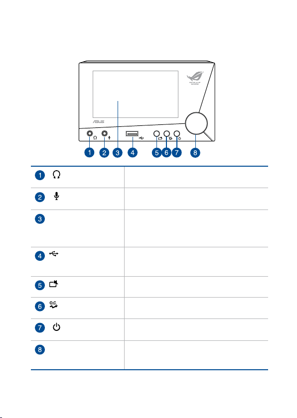
Hardware Overview
Front view
Headphone out
port
Microphone in
port
LCD panel Displays the system time, CPU speed,
USB 2.0 port Charges your smart device when in soft-off
Escape mode
button
CPU Level Up
OC button
LCD panel power
button
Selection knob Rotates to go to the desired item or adjust the
Supports headphones and speakers.
Connects to a microphone.
temperature of motherboard and CPU, system
fan duty cycles, audio EQ modes, and the
current mode or status of the device.
mode. Functions as a normal USB 2.0 port
when system is on.
Hides the current screen, mute the sound, and
display the desktop.
Performs overclocking.
Turns the LCD panel display of the ROG Front
Base on/off.
values. Conrms changes or selection when
pressed.
5
Page 6
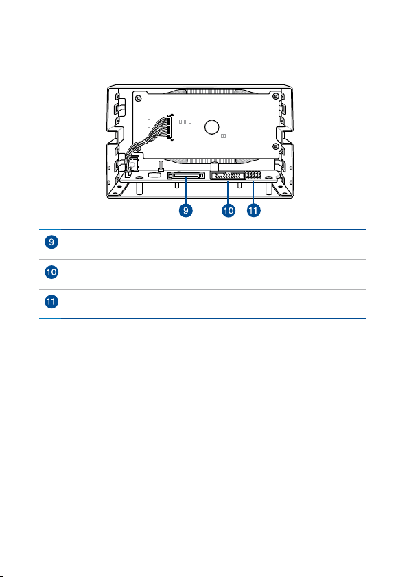
Rear view
SATA power
connector
ROG_EXT
connector
AAFP connector Connects with the motherboard’s Front panel audio
6
Connects to a SATA power cable from the Power
supply for additional power source.
Connects with the motherboard’s ROG_EXT
connector.
connector (AAFP) for high-denition audio support.
Page 7

Installing the ROG Front Base
IMPORTANT! Allot two (2) empty 5.25-inch drive bays for ROG Front Base
installation.
To install the ROG Front Base:
1. Connect the ROG_EXT cable and the AAFP cable to their respective
connectors on the ROG Front Base.
ROG_EXT cable AAFP cable
2. Insert the other end of the ROG_EXT cable and the AAFP cable through the
two empty 5.25-inch drive trays.
two (2) empty 5.25-inch drive bays
7
Page 8

3. Align and place the ROG Front Base with its connected cable to the two (2)
AAFP
ROG_EXT
empty 5.25-inch drive bays.
NOTE: Ensure that the screw holes on the ROG Front Base matches the screw
holes on the PC chassis.
4. Secure the ROG Front Base to the PC chassis using the bundled set of
screws.
5. Connect the other end of the ROG_EXT cable and the AAFP cable to their
respective connectors on the motherboard.
AAFP
ROG_EXT
8
Page 9

6. Connect a SATA power cable from the power supply and to the SATA power
REPUBLIC OF
GAMERS
connector on the ROG Front Base.
PC chassis
SATA power cable
7. Turn on the computer.
9
Page 10

Installing the driver
The support DVD that comes with your ROG Front Base contains drivers to ensure
compatibility between the ROG Front Base device and the motherboard.
NOTES:
• The contents of the support DVD are subject to change at any time without
notice. Visit the ASUS website at www.asus.com for the latest updates.
• Update your motherboard to the latest BIOS. Refer to your motherboard
manual on how to update your BIOS.
To install the ROG Front Base driver:
1. Place the support DVD into the optical drive.
NOTE: If you are running Windows® 8 or Windows® 8.1, launch the Desktop.
2. Browse the content then double-click or tap Setup.exe.
3. From the ASUS InstAll window, click the
Drivers tab then click ASUS InstAll.
10
Page 11

4. Select the Install drivers and recommended tools automatically from
InstAll (recommended) option button then click OK.
5. From the ASUS InstAll window, tick the ROG Front Base and Realtek Audio
Driver check boxes then click Go.
Do not turn off your computer during the installation process.
6. When done, follow onscreen instructions to complete the installation.
11
Page 12

GHz
The ROG Front Base LCD panel
The 4-inch LCD of the ROG Front Base provides at-a-glance view of all the
information about your system whether your system is on or powered off.
To turn off/on the LCD, press the LCD panel power button on the front panel.
The LCD panel displays the following information:
Clock Displays system time.
Fan speed gauge Displays the duty cycles of CPU fans 1 and 2,
Mode/Status indicator Displays the current status of ROG Front
Temperature gauge Displays the CPU and motherboard (MB)
CPU Level Up OC icon Appears when the CPU Level Up OC button
Audio Equalization bar Shows the current audio EQ mode in use.
Chassis fans 1, 2, and 3.
Base. The information displayed vary
depending on the mode of the device.
temperature.
is pressed.
CPU Frequency gauge Displays the current CPU Frequency or speed.
12
Page 13

Using the ROG Front Base
Overclocking with the CPU Level Up OC button
To perform overclocking, press the CPU Level Up OC button on the front panel of the
device for an instant CPU performance boosts.
NOTES:
• The following shows the cycle when your press the CPU Level Up OC button
repeatedly:
(Normal mode)
• The overclocking values of LV1 and LV2 depend on the CPU type or
motherboard installed.
• Restore the system to its default settings if the system becomes unstable. For
more details, refer to the BIOS section of your motherboard’s user manual.
13
Page 14

Adjusting system fan’s duty cycle
Depending on the system fan installed on your system, ROG Front Base allows you
to adjust the individual duty cycle of the installed fans.
NOTES:
To control and monitor an installed 3-pin DC control fan or a 4-pin PWM fan
using the ROG Front Base, enable each of the fan rst in your BIOS.
• To enable the 4-pin PWM fan, go to BIOS > Monitor > Fan Speed
Control
• To enable the 3-pin DC control fan, go to BIOS > Monitor > Fan Speed
Contro
To manually adjust a fan’s duty cycle setting:
1. Press and hold the Selection knob until
Mode/Status Indicator.
2. Rotate the Selection knob to select a fan.
3. Press the knob to conrm your selection.
4. Rotate the knob to adjust the value of the fan’s duty cycle.
NOTE: ROG Front Base allows duty cycle adjustments in percentage (from 0%
to 100%) instead of the actual fan speed.
5. Press the Selection knob to conrm the changes.
then set CPU Q-Fan Control to [Auto].
l then set CPU Q-Fan Control to [Advance Mode].
is displayed on the
14
Page 15

Using the Escape mode button
The Escape Mode button located on the front panel of the ROG Front Base is a great
privacy tool. When pressed, it instantly hides the current screen, mutes the system
sound, and displays the desktop.
NOTES:
• To unmute or enable the sound, press the Selection knob repeatedly
until is displayed on the Mode/Status indicator then
rotate the Selection knob to adjust the volume to the desired level.
• When the Escape button is pressed, it minimizes the screen of the
application to the taskbar. To restore the screen, click the application’s
icon on the taskbar.
Activating the USB Charger mode
The USB Charger mode allows the USB 2.0 port on the front panel to charge smart
devices such as mobile phones and tablets when the system is on the soft-off mode
(S5).
To activate the USB Charger mode:
1. While the system is on a soft-off mode (S5), rotate the Selection knob until
2. Press the Selection knob to conrm your selection.
3. Connect the device to charge to the USB 2.0 port.
NOTES:
•
USB Charger mode automatically switches to the normal mode when the
system is turned on. In normal mode, the USB 2.0 port supports data or digital
transmission.
• For more information on the list of supported devices, visit www.asus.com.
is displayed on the Mode/Status Indicator.
15
Page 16

Selecting an audio equalization mode
The ROG Front Base has four audio equalization (EQ) modes specically designed
for gaming and a music mode for listening to your favorite audio les.
To select an audio EQ mode, press and hold the Selection knob until
is displayed on the Mode/Status Indicator then rotate the Selection knob to select a
mode.
Adjusting the system volume
To adjust the system volume, press the Selection knob repeatedly until
adjust the volume level.
is displayed on the Mode/Status Indicator then rotate the knob to
Understanding the Debug mode
The debug mode provides instant information about the status of your system. It is
automatically activated, and only active, during the booting process.
In debug mode, the 2-digit error code of the motherboard’s Q-Code LED is directly
displayed on the device’s Mode/Status indicator in real-time during the bootup
process.
The debug mode automatically switches to the normal mode after a successful boot
and the system is in the Operating System (OS).
NOTE: Refer to your motherboard manual for the complete list of the 2-digit
error codes.
16
Page 17

EC Declaration of Conformity
We, the undersigned,
Manufacturer:
ASUSTeK COMPUTER INC.
Address, City:
4F, No. 150, LI-TE Rd., PEITOU, TAIPEI 112, TAIWAN
Country:
TAIWAN
Authorized representative in Europe:
ASUS COMPUTER GmbH
Address, City:
HARKORT STR. 21-23, 40880 RATINGEN
Country:
GERMANY
declare the following apparatus:
Product name : Front panel
Model name : Pront Base
conform with the essential requirements of the following directives:
2004/108/EC-EMC Directive
EN 55022:2010+AC:2011
EN 61000-3-2:2006+A2:2009
EN 55013:2001+A1:2003+A2:2006
EN 55024:2010
EN 61000-3-3:2008
EN 55020:2007+A11:2011
1999/5/EC-R &TTE Directive
EN 300 328 V1.7.1(2006-10)
EN 300 440-1 V1.6.1(2010-08)
EN 300 440-2 V1.4.1(2010-08)
EN 301 511 V9.0.2(2003-03)
EN 301 908-1 V5.2.1(2011-05)
EN 301 908-2 V5.2.1(2011-07)
EN 301 893 V1.6.1(2011-11)
EN 302 544-2 V1.1.1(2009-01)
EN 302 623 V1.1.1(2009-01)
EN 50360:2001
EN 62479:2010
EN 50385:2002
EN 62311:2008
EN 301 489-1 V1.9.2(2011-09)
EN 301 489-3 V1.4.1(2002-08)
EN 301 489-4 V1.4.1(2009-05)
EN 301 489-7 V1.3.1(2005-11)
EN 301 489-9 V1.4.1(2007-11)
EN 301 489-17 V2.2.1(2012-09)
EN 301 489-24 V1.5.1(2010-09)
EN 302 326-2 V1.2.2(2007-06)
EN 302 326-3 V1.3.1(2007-09)
EN 301 357-2 V1.4.1(2008-11)
EN 302 291-1 V1.1.1(2005-07)
EN 302 291-2 V1.1.1(2005-07)
2006/95/EC-LVD Directive
EN 60950-1 / A12:2011 EN 60065:2002 / A12:2011
2009/125/EC-ErP Directive
Regulation (EC) No. 1275/2008
Regulation (EC) No. 642/2009
Regulation (EC) No. 278/2009
Regulation (EC) No. 617/2013
2011/65/EU-RoHS Directive
Ver. 130816
CE marking
Declaration Date: 16/08/2013
Year to begin affixing CE marking:2013
Position : CEO
Name : Jerry Shen
Signature :
__________
(EC conformity marking)
DECLARATION OF CONFORMITY
Per FCC Part 2 Section 2. 1077(a)
Responsible Party Name: Asus Computer International
Address: 800 Corporate Way, Fremont
, CA 94539.
Phone/Fax No: (510)739-3777/(510)608-4555
hereby declares that the product
Product Name : Front Panel
Model Number : Front Base
Conforms to the following specifications:
FCC Part 15, Subpart B, Unintentional Radiators
Supplementary Information:
This device complies with part 15 of the FCC Rules. Operation is subject to
the following two conditions: (1) This device may not cause harmful
interference, and (2) this device must accept any interference received,
including interference that may cause undesired operation.
Representative Person’s Name : Steve Chang / President
Signature :
Date : Jun. 16, 2013
Ver. 120601
Appendix
17
Page 18

Contact Info
ASUSTeK COMPUTER INC.
Address 15 Li-Te Road, Peitou, Taipei, Taiwan 11259
Telephone +886-2-2894-3447
Fax +886-2-2890-7798
E-mail info@asus.com.tw
Web site http://www.asus.com
Technical Support
Telephone +86-21-3842-9911
Fax +86-21-5866-8722, ext. 9101#
Online support http://support.asus.com/techserv/techserv.aspx
ASUS COMPUTER INTERNATIONAL (America)
Address 800 Corporate Way, Fremont, CA 94539, USA
Telephone +1-510-739-3777
Fax +1-510-608-4555
Web site http://usa.asus.com
Technical Support
Support fax +1-812-284-0883
General support +1-812-282-2787
Online support http://support.asus.com/techserv/techserv.aspx
ASUS COMPUTER GmbH (Germany and Austria)
Address Harkort Str. 21-23, D-40880 Ratingen, Germany
Fax +49-2102-959931
Web site http://www.asus.com/de
Online contact http://eu-rma.asus.com/sales
Technical Support
Telephone +49-2102-5789555
Support Fax +49-2102-959911
Online support http://support.asus.com/techserv/techserv.aspx
18
 Loading...