

Page 1

Wireless Cable Modem
User's Manual
Page 2

Copyright
Copyright © 2001 This Company. All Rights Reserved.
SPECIFICA TIONS AND INFORMA TION CONT AINED IN THIS DOCUUMENT ARE FURNISHED FOR INFORMA TIONAL
USE ONL Y , AND ARE SUBJECT T O CHANGE A T ANY TIME WITHOUT NOTICE, AND SHOULD NOT BE CONSTRUED
AS A COMMITMENT BY THIS COMPANY. THIS COMPANY ASSUMES NO RESPONSIBILITY OR LIABILITY FOR
ANY ERRORS OR INACCURACIES THAT MAY APPEAR IN THIS DOCUMENT, INCLUDING THE PRODUCTS AND
SOFTWARE DESCRIBED IN IT.
Product Name: Wireless Cable Modem
Manual Revision: 1.00 E742
Release Date: July 2001
2
Wireless Cable Modem User’s Manual
Page 3

Contents
Contents
Contents.......................................................................................................... 3
Overview.....................................................................................................................5
Features .....................................................................................................................5
Package Contents ......................................................................................................5
Introduction .................................................................................................... 5
Preparations ................................................................................................... 6
System Requirements ................................................................................................6
Installing a Network Card ...........................................................................................6
Preparations ................................................................................................... 7
TCP/IP Settings ..........................................................................................................7
Front Panel ................................................................................................................. 8
Front Panel Indicators ................................................................................................9
Using the Wireless Cable Modem................................................................. 9
Rear Panel................................................................................................................10
Installing the Wireless Cable Modem ....................................................................... 11
Using the Wireless Cable Modem............................................................... 12
Connecting the Wireless Cable Modem ...................................................................12
Rear Panel Connections ........................................................................................12
Cable Service Connections....................................................................................12
Wireless Settings......................................................................................................13
WEP Settings ...........................................................................................................15
Wireless Advanced Setting.......................................................................................16
Product Specifications ................................................................................ 20
Wireless Cable Modem User’s Manual
3
Page 4

4
Wireless Cable Modem User’s Manual
Page 5

Introduction
Overview
Features
Thank you for purchasing this DOCSIS-compliant wireless cable modem. This wireless cable
modem delivers the highest performance in data over cable technology. Ideal for home and
small business users, this easy-to-use communication device offers reliable connectivity as well
as remarkable data transfer rates—100 times faster than a 56K dial-up modem. Once the cable
modem is powered up, you are online to enjoy real-time 3D animation, video conferencing, and
perform other data intensive operations.
• MCNS DOCSIS 1.0 compliant
• Support for 6MHz downstream and 200K-3200KHz upstream cable channel bandwidth
• Autodetection of 64QAM or 256QAM
• Network management protocol support for SNMPv1/v2c and DOCSIS 1.0 MIBs
• Data Encryption Standard (DES) and Baseline Privacy Interface (BPI) compliant
• 4 port 10/100 Integrated Switch
• Wireless LAN IEEE 802.11b
• Supports MDI/MDI-X auto crossover
• Self-diagnoses available through front panel LEDs
Package
Contents
• Software upgradeable
(1) Wireless Cable Modem (1) CAT.5 Ethernet cable (RJ-45)
(1) AC power adapter (1) User’s Manual
Wireless Cable Modem User’s Manual
5
Page 6
Preparations
System
Requirements
Installing a
Network Card
Before connecting the wireless cable modem to your PC, make sure your system is equipped
with a LAN controller or wireless LAN module and supports the TCP/IP protocol.
If your system does not have an embedded LAN controller , you must install a network interface
card as instructed below (assuming that you are using an Ethernet card under the operating
system of Windows 98):
1. Install an Ethernet card on your motherboard.
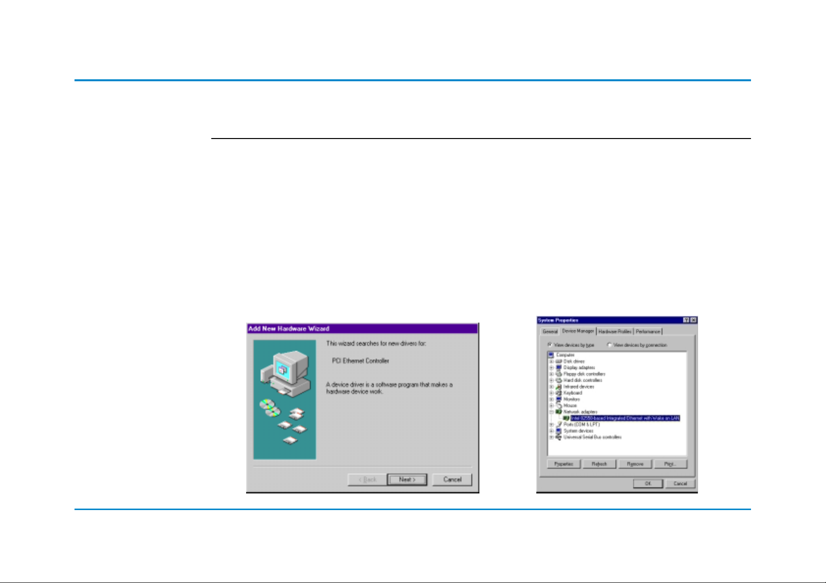
2. Power up your PC and follow the Add New
Hardware Wizard’s instructions to install the
driver . When asked to restart your computer
at the end of the installation, click Yes.
3. After restarting the system, right-click
My Computer on the desktop, select
Properties, click the Device Man-
ager tab, and then double-click
Network adapters to confirm that the
Ethernet driver is properly installed.
6
Wireless Cable Modem User’s Manual
Page 7

Preparations
TCP/IP Settings
After the TCP/IP protocol is installed, restart your computer and consult the installation guide
provided by your cable operator to complete TCP/IP configurations.
Wireless Cable Modem User’s Manual
7
Page 8

Using the Wireless Cable Modem
Front Panel
12345
POWER STATUS USBCABLE PC
8
Wireless Cable Modem User’s Manual
Page 9

Using the Wireless Cable Modem
Front Panel
Indicators
LED Indicator State Description
1. ON Wireless LAN Card is ready
Flashing Data transmitting between cable modem and wireless network
OFF ———
2. ON Modem is powered ON
OFF Modem is powered OFF (if adapter connected, use correct adpater.)
3. ON Ethernet link is ready
Flashing Data transmitting between cable modem and ethernet network
OFF ———
4. ON Full duplex
OFF Half duplex
5. 100 ON 100 BaseTX
OFF 10 BaseT
6. ON No traffic
Flashing Data transmitting between cable modem and cable operator’s network
ON Downstream channel has been locked
Flashing Searching for Downstream channel
7. ON Modem successfully registered on cable operator’s network
Flashing Modem is registering on cable operator’s network
OFF ———————-
8. ON Error (Try resetting modem; if still error, contact customer support)
OFF Normal operation
Wireless Cable Modem User’s Manual
9
Page 10

Using the Wireless Cable Modem
Rear Panel
1 2 3 4 65
DC +5V/2.5A
1. DC +5V/2.5A Power Input Jack
The provided power adapter converts AC power to DC power for use with this jack.
Power supplied through this jack will supply power to the cable modem.
2. RF Connector
The connector may be located right next to the power input jack or the serial port. The
F-Type female connector allows cable data communication between the cable modem
and the cable service provider through a coaxial cable.
3. Reset Switch
The reset button, when pressed, resets the cable modem without the need to unplug
the power cord.
ResetCable Console USB 10/100-BaseT
10
4. Serial Port
The 9-pin D-sub serial port supports the RS-232 terminal interface for advanced cable
modem management.
5. 10/100-BaseT LAN Ports
The LAN ports support 10Base-T or 100Base-TX networks. These ports allow your PC or
Ethernet hub to be connected to the cable modem through a CA T.5 twisted pair LAN cable.
Wireless Cable Modem User’s Manual
Page 11

Using the Wireless Cable Modem
Installing the
Wireless
Cable Modem
Take the following steps to accomplish the installation procedure:
1. Connect the cable TV coaxial cable to the input connector of a signal splitter.
2. Connect a coaxial cable from one of the output connectors on the splitter to the input
connector of your TV set.
3. Use another coaxial cable to connect the other output connector on the splitter and the
RF connector on the rear panel of the wireless cable modem.
4. Connect the LAN cable from the LAN port on your computer to the LAN port on the rear
panel of the wireless cable modem. You can also connect to a PC with wireless PC
card (see “Configuring Wireless Settings”)
5. Connect the AC power adapter to the DC +5V/2.5A input jack on the rear panel of the
wireless cable modem. Plug in the AC power adapter to an electrical outlet.
6. Powering Up: When all connections have been properly made and the power is ON,
the wireless cable modem will automatically start the self-test and search for the active
cable channel provided by your cable operator.
NOTES:
• If you are not using a television on the cable line, you may skip steps 1 to 3 and
connect the cable TV coaxial cable directly to the RF connector on the rear panel of the
cable modem.
• Install the Wiireless cable modem as high as possible.
Wireless Cable Modem User’s Manual
11
Page 12

Using the Wireless Cable Modem
Connecting
the Wireless
Cable Modem
DC +5V/2.5A
To Electrical Outlet
Rear Panel Connections
ResetCable Console USB 10/100-BaseT
Step 3
T o Splitter or Cable
Network
Step 4Step 5
To PC
Wireless
To Cable
Network
2-Way
Splitter
Cable
Modem
Splitter
Cable Modem
TV
Cable Service Connections
Computer
12
Wireless Cable Modem User’s Manual
Page 13

Wireless Settings
Wireless
Settings
Configuring the PC’s IP Address Using a WEB Browser
1) Setup your PC’s IP address to be
assigned dynamically
2) Connect the Ethernet cable to the
modem
3) Power on the modem without connect
to the CATV cable
4) Use “ipconfig” or “winipcfg” windows
command to get the IP address for
your LAN adapter
5) Check if your IP address is assigned
in the domain 192.168.100.x
6) Open a browser and connect to the IP
address 192.168.100.1
7) You can see the Wireless setup
manual
Wireless Cable Modem User’s Manual
13
Page 14

Wireless Settings
Click Wireless you can change ESSID/Channel/WEP Type/AP mode/WLAN Enable.
ESSID: ESS stands for “Extended Service Set”. The ESS ID is the name shared among all
points in a wireless network system. The ESSID must be identical for all points in the system
and must not exceed over 30 characters. After changing, please click “Apply” button for setup.
Domain: Domain indicates the channel number for each country which is allowed to be used.
For Example, “Japanese All” is the domain for the Japan for which the user can have 14 channels for his application.
Channel: The value of channel can be selected from channel 1 to 11 for the FCC domain and
between channels 1 to 13 for ETSI domain, as well as channel 1 to 14 for Japanese domain.
WEP: Wired Equivalent Privacy is a data privacy security mechanism based on a 40 bit shared
key algorithm. There are the options for “Disable” to disable the WEP function or enable the
WEP with “64Bit” or “128Bit”. Enable the WEP and click the “Apply” will guide you another page
for WEP key setting.
AP Mode: “Enable” means the Wireless cable modem works only as an Access Point without
cable modem function. To have the communication with CMTS, please click the “Disable”
14
WLAN Enable: “Disable” means the Wireless cable modem works only as a normal cable
modem without active the wireless functions. To have the communication with Wireless station,
please click the “Enable”
If you want to save the configuration data, please click Apply button and afterwards it will
become default configuration. After change the new parameters to the W ireless Cable modem,
you need to reset the modem to active the new settings.
Wireless Cable Modem User’s Manual
Page 15

Wireless Settings
WEP Settings
WEP Manual: “Automatic”
Passphrase:To generate the key, if
the WEP is enabled. This is the code
used while a wireless
point is to log on to the network thru
the WEP encryption function. All
points in the Wireless Network system have to have the same key
shared which is set with a maximum
of 32 alphanumeric characters.
WEP Key Setting: This setting key is
to configure the WEP encryption in the
wireless network
system. To generate the key, please
insert the same PassPhrase in the
field and click the “Done” to create the
encryption key which must be same
as the every points on the Wireless
Network system. Then Click the “Apply” to store the setting keys.
Wireless Cable Modem User’s Manual
15
Page 16

Wireless Settings
Wireless
Advanced
Setting
Click Wireless Advanced Setting for setting up some other wireless functions.
16
Default password: 12345
Push button: Apply then the screen will show the as below stated web page
Wireless Cable Modem User’s Manual
Page 17

Wireless Settings
Wireless Cable Modem User’s Manual
17
Page 18

Wireless Settings
Beacon Interval: The Beacon Interval specifies the duration between the beacon packets. The AP shall
periodically transmit special frames called beacons that contain information for synchronization between
the participating stations. The range for the Beacon Interval is between 20-1000 with a typical value of 100.
RTS Threshold: The value should remain on its default setting 2432 bytes. If you encounter any date flow,
only minor modifications are recommended.
Fragmentation Threshold: The value indicates how much of the network resources devoted to recovering
packet errors. The value should remain at its default setting of 2432 bytes. If you have decreased this value
and experience high packet error rates, you can increase it again, but will likely decrease overall network
performance.
Authentication T ype: It can be selected for “Open System”, “Shared Key” or “Both” for the indication of an
authentication algorithm. “Shared Key” is to be selected while the WEP for PC card and Access Point are
both enabled and setup with the same passphrase key. And “Open System” is for disabled WEP in Wireless Network system.
DTIM Interval: DTIM is always a multiple of the beacon Period and determines how often a beacon contains a Delivery Traf fic Indicator Message (DTIM). This message informs stations in power-save mode that
a packet is waiting for them. Suggested value is 2.
18
Preamble Type: There is the “Long” or “Short” selection to ensure that systems receiving the information
correctly interpret when the data transmission starts. To select “long” Preamble may be used to minimize
overhead and “Long” to maximize the network data throughput. The default value will be set for “Long”.
Basic Rate: The basic transfer rate is to set based on the speed of the wireless network system. For slower
network system is to be selected 1-2 Mbps and faster network 1-2-5.5-11 Mbps.
Auto Rate Fall Back setting allows you to have flexible automatic data rate adjustment according to the
connection situation.
Wireless Cable Modem User’s Manual
Page 19

Product Certifications
Wireless Cable Modem User’s Manual
19
Page 20

Product Specifications
Software Specifications
Protocol Support • MCNS DOCSIS 1.0, TCP/IP, UDP , ARP, ICMP, SNMP, TFTP, TOD, BOOTP, SYSLOG, R7 Interface
RF Interface • F-Type female 75ohm connector
Bridging • Support for unicast, broadcast, and multicast IP packets
• Variable-length packet cable Meida Access Control (MAC) transport layer
• Mix of contention and reservation-based upstream transmission
Management Operations
QoS • Quality of Service of Mac Layer
MIBs Support • RFC 1907: System group, SNMP group, SNMPv2 group
• SNMPv1/v2c
• RFC 1902: SMIv2
• RFC 1903: Texture conventions
• RFC 2011: IP group, ICMP group
• RFC 2013: UDP group
• RFC 2233: Interface group
• RFC 2358: Ethernet-like Interface group
• RFC 2571: Architecture for describing SNMP management frameworks
• RFC 1493: Bridge
• RFC 2669: MCNS Cable Device
• RFC 2670: MCNS Radio Frequency Interface
• IETF Draft: MCNS Baseline Privacy Interface
20
Wireless Cable Modem User’s Manual
Page 21

Product Specifications
RF Receiver/Transmitter Specifications
Downstream (Receiver) Upstream (Transmitter)
Frequency Range • 88 to 860 MHz • 5 to 42 MHz
Modulation • 64QAM • QPSK
• 256QAM • 16QAM
Signal Rate • 30Mbps/64QAM • QPSK 320Kps to 5.12Mbps
• 42.8Mbps/256QAM • 16QAM 640Kbps to 10.24Mbps
Channel Bandwidth • 6MHz • 200K, 400K, 800K 1.6M, 3.2MHz
FEC • RS (128, 122) Trellis • Reed Solomon
Receive Level • -15 — +15dBmV • QPSK: +8 — +58dBmV
(Digital Signal) • 16QAM: +8 — +55dBmV
Security • DES decryption: DOCSIS Baseline Privacy (BPI), 56-bit DES and 168-bit triple-DES en-
cryption, as controlled by the headend and configuration files
Wireless Cable Modem User’s Manual
21
Page 22

Product Specifications
Wireless LAN IEEE8.2.11b Specifications
Emission Type Direct Sequence Spectrum (DSSS)
RF Frequency Japan Band : 2471MHz - 2497MHz
America, Europe and extended Japan Brand : 2400MHz – 2483.5MHz
Spain : 2455MHz – 2475MHz
France : 2446.5MHz – 2483.5MHz
Operating Channel FCC 1-11, ETSI 1-13, France 10-13, Spain 10-11, Japan 1-14
Radio Chipset Intersil PRISM II
Media Access CSMA/CA ( Collision Avoidance ) with ACK
Transmitter Power 12 dBm min.
Data Modulation Type BPSK, QPSK and CCK
Data Rate 11 / 5.5 / 2 / 1Mbps with auto fallback
Security 64/128bit Wired Equivalent Privacy ( WEP ) Data Encryption
Receiver Sensitivity -80 dBm ( Typically )
22
Wireless Cable Modem User’s Manual
 Loading...