

ASUS E45m1-M Pro User Manual

E45M1-M PRO
Motherboard

E8018
Second Edition (V2)
December 2012
Copyright © 2012 ASUSTeK Computer Inc. All Rights Reserved.
No part of this manual, including the products and software described in it, may be reproduced,
transmitted, transcribed, stored in a retrieval system, or translated into any language in any form or by any
means, except documentation kept by the purchaser for backup purposes, without the express written
permission of ASUSTeK Computer Inc. (“ASUS”).
Product warranty or service will not be extended if: (1) the product is repaired, modied or altered, unless
such repair, modication of alteration is authorized in writing by ASUS; or (2) the serial number of the
product is defaced or missing.
ASUS PROVIDES THIS MANUAL “AS IS” WITHOUT WARRANTY OF ANY KIND, EITHER EXPRESS
OR IMPLIED, INCLUDING BUT NOT LIMITED TO THE IMPLIED WARRANTIES OR CONDITIONS OF
MERCHANTABILITY OR FITNESS FOR A PARTICULAR PURPOSE. IN NO EVENT SHALL ASUS, ITS
DIRECTORS, OFFICERS, EMPLOYEES OR AGENTS BE LIABLE FOR ANY INDIRECT, SPECIAL,
INCIDENTAL, OR CONSEQUENTIAL DAMAGES (INCLUDING DAMAGES FOR LOSS OF PROFITS,
LOSS OF BUSINESS, LOSS OF USE OR DATA, INTERRUPTION OF BUSINESS AND THE LIKE),
EVEN IF ASUS HAS BEEN ADVISED OF THE POSSIBILITY OF SUCH DAMAGES ARISING FROM ANY
DEFECT OR ERROR IN THIS MANUAL OR PRODUCT.
SPECIFICATIONS AND INFORMATION CONTAINED IN THIS MANUAL ARE FURNISHED FOR
INFORMATIONAL USE ONLY, AND ARE SUBJECT TO CHANGE AT ANY TIME WITHOUT NOTICE,
AND SHOULD NOT BE CONSTRUED AS A COMMITMENT BY ASUS. ASUS ASSUMES NO
RESPONSIBILITY OR LIABILITY FOR ANY ERRORS OR INACCURACIES THAT MAY APPEAR IN THIS
MANUAL, INCLUDING THE PRODUCTS AND SOFTWARE DESCRIBED IN IT.
Products and corporate names appearing in this manual may or may not be registered trademarks or
copyrights of their respective companies, and are used only for identication or explanation and to the
owners’ benet, without intent to infringe.
Offer to Provide Source Code of Certain Software
This product may contain copyrighted software that is licensed under the General Public License (“GPL”)
and under the Lesser General Public License Version (“LGPL”). The GPL and LGPL licensed code in this
product is distributed without any warranty. Copies of these licenses are included in this product.
You may obtain the complete corresponding source code (as dened in the GPL) for the GPL Software,
and/or the complete corresponding source code of the LGPL Software (with the complete machinereadable “work that uses the Library”) for a period of three years after our last shipment of the product
including the GPL Software and/or LGPL Software, which will be no earlier than December 1, 2011, either
(1) for free by downloading it from http://support.asus.com/download;
or
(2) for the cost of reproduction and shipment, which is dependent on the preferred carrier and the location
where you want to have it shipped to, by sending a request to:
ASUSTeK Computer Inc.
Legal Compliance Dept.
15 Li Te Rd.,
Beitou, Taipei 112
Taiwan
In your request please provide the name, model number and version, as stated in the About Box of the
product for which you wish to obtain the corresponding source code and your contact details so that we
can coordinate the terms and cost of shipment with you.
The source code will be distributed WITHOUT ANY WARRANTY and licensed under the same license as
the corresponding binary/object code.
This offer is valid to anyone in receipt of this information.
ASUSTeK is eager to duly provide complete source code as required under various Free Open Source
Software licenses. If however you encounter any problems in obtaining the full corresponding source code
we would be much obliged if you give us a notication to the email address gpl@asus.com, stating the
product and describing the problem (please do NOT send large attachments such as source code archives
etc to this email address).
ii

Contents
Notices ......................................................................................................... vi
Safety information ..................................................................................... vii
About this guide ....................................................................................... viii
E45M1-M PRO specications summary ................................................... ix
Chapter 1: Product introduction
1.1 Welcome! ...................................................................................... 1-1
1.2 Package contents ......................................................................... 1-1
1.3 Special features ............................................................................ 1-1
1.3.1 Product highlights ........................................................... 1-1
1.3.2 Innovative ASUS features ............................................... 1-2
1.4 Before you proceed ..................................................................... 1-4
1.5 Motherboard overview ................................................................. 1-5
1.5.1 Placement direction ........................................................ 1-5
1.5.2 Screw holes .................................................................... 1-5
1.5.3 Motherboard layout ......................................................... 1-6
1.5.4 Layout contents ............................................................... 1-6
1.6 Accelerated Processing Unit (APU) ........................................... 1-7
1.6.1 Installing the CPU fan ..................................................... 1-7
1.6.2 Uninstalling the CPU fan ................................................. 1-8
1.7 System memory ........................................................................... 1-8
1.7.1 Overview ......................................................................... 1-8
1.7.2 Memory congurations .................................................... 1-9
1.8 Expansion slots .......................................................................... 1-10
1.8.1 Installing an expansion card ......................................... 1-10
1.8.2 Conguring an expansion card ..................................... 1-10
1.8.3 PCI slots ........................................................................ 1-10
1.8.4 PCI Express x1 slot ....................................................... 1-10
1.8.5 PCI Express x16 slot ..................................................... 1-10
1.9 Jumpers ...................................................................................... 1-11
1.10 Connectors ................................................................................. 1-12
1.10.1 Rear panel connectors .................................................. 1-12
1.10.2 Internal connectors ....................................................... 1-14
1.11 Onboard switches ...................................................................... 1-20
1.12 Onboard LEDs ............................................................................ 1-21
iii

Contents
1.13 Software support ........................................................................ 1-22
1.13.1 Installing an operating system ...................................... 1-22
1.13.2 Support DVD information .............................................. 1-22
Chapter 2: BIOS information
2.1 Managing and updating your BIOS ............................................ 2-1
2.1.1 ASUS Update utility ........................................................ 2-1
2.1.2 ASUS EZ Flash 2 ............................................................ 2-2
2.1.3 ASUS CrashFree BIOS 3 utility ...................................... 2-3
2.1.4 ASUS BIOS Updater ....................................................... 2-4
2.2 BIOS setup program .................................................................... 2-7
2.3 Main menu .................................................................................. 2-11
2.3.1 System Language [English] ...........................................2-11
2.3.2 System Date [Day xx/xx/xxxx] ........................................2-11
2.3.3 System Time [xx:xx:xx] ..................................................2-11
2.3.4 Security ..........................................................................2-11
2.4 Ai Tweaker menu ........................................................................ 2-13
2.4.1 Ai Overclock Tuner [Auto] ............................................. 2-14
2.4.2 Memory Frequency [Auto] ............................................. 2-14
2.4.3 EPU Power Saving Mode [Disabled] ............................ 2-14
2.4.4 OC Tuner ...................................................................... 2-14
2.4.5 DRAM Timing Control ................................................... 2-14
2.4.6 CPU Offset Mode Sign [+] ............................................. 2-14
2.4.7 VDDNB Offset Mode Sign [+] ........................................ 2-15
2.4.8 DRAM Voltage [Auto] .................................................... 2-15
2.4.9 SB 1.1V Voltage [Auto] ................................................. 2-15
2.4.10 APU 1.8V Voltage [Auto] ............................................... 2-15
2.4.11 APU 1.05V Voltage [Auto] ............................................. 2-15
2.4.12 APU Spread Spectrum [Auto] ....................................... 2-15
2.5 Advanced menu ......................................................................... 2-16
2.5.1 CPU Conguration ........................................................ 2-16
2.5.2 SATA Conguration ....................................................... 2-17
2.5.3 USB Conguration ........................................................ 2-17
2.5.4 NB Conguration ........................................................... 2-18
2.5.5 Onboard Devices Conguration .................................... 2-18
2.5.6 APM .............................................................................. 2-19
iv

Contents
2.6 Monitor menu ............................................................................. 2-21
2.6.1 CPU Temperature / MB Temperature [xxxºC/xxxºF] ...... 2-21
2.6.2 CPU / Chassis Fan Speed ............................................ 2-21
2.6.3 CPU Q-Fan Control [Enabled] ...................................... 2-22
2.6.4 Chassis Q-Fan Control [Enabled] ................................. 2-23
2.6.5 CPU Voltage, 3.3V Voltage, 5V Voltage, 12V Voltage .. 2-23
2.6.6 Anti Surge Support [Disabled] ....................................... 2-23
2.7 Boot menu .................................................................................. 2-24
2.7.1 Bootup NumLock State [On] ......................................... 2-24
2.7.2 Full Screen Logo [Enabled] ........................................... 2-24
2.7.3 Wait for ‘F1’ If Error [Enabled] ....................................... 2-24
2.7.4 Option ROM Messages [Force BIOS] ........................... 2-25
2.7.5 Setup Mode [EZ Mode] ................................................. 2-25
2.7.6 Boot Option Priorities .................................................... 2-25
2.7.7 Boot Override ................................................................ 2-25
2.8 Tools menu ................................................................................. 2-26
2.8.1 ASUS EZ Flash 2 Utility ................................................ 2-26
2.8.2 ASUS O.C. Prole ......................................................... 2-26
2.9 Exit menu .................................................................................... 2-27
v

Notices
Federal Communications Commission Statement
This device complies with Part 15 of the FCC Rules. Operation is subject to the following two
conditions:
• This device may not cause harmful interference, and
• This device must accept any interference received including interference that may cause
undesired operation.
This equipment has been tested and found to comply with the limits for a Class B digital
device, pursuant to Part 15 of the FCC Rules. These limits are designed to provide
reasonable protection against harmful interference in a residential installation. This
equipment generates, uses and can radiate radio frequency energy and, if not installed
and used in accordance with manufacturer’s instructions, may cause harmful interference
to radio communications. However, there is no guarantee that interference will not occur
in a particular installation. If this equipment does cause harmful interference to radio or
television reception, which can be determined by turning the equipment off and on, the user
is encouraged to try to correct the interference by one or more of the following measures:
•
Reorient or relocate the receiving antenna.
•
Increase the separation between the equipment and receiver.
•
Connect the equipment to an outlet on a circuit different from that to which the receiver is
connected.
•
Consult the dealer or an experienced radio/TV technician for help.
The use of shielded cables for connection of the monitor to the graphics card is required
to assure compliance with FCC regulations. Changes or modications to this unit not
expressly approved by the party responsible for compliance could void the user’s authority
to operate this equipment.
Canadian Department of Communications Statement
This digital apparatus does not exceed the Class B limits for radio noise emissions from
digital apparatus set out in the Radio Interference Regulations of the Canadian Department
of Communications.
This class B digital apparatus complies with Canadian ICES-003.
ASUS Recycling/Takeback Services
ASUS recycling and takeback programs come from our commitment to the highest standards
for protecting our environment. We believe in providing solutions for you to be able to
responsibly recycle our products, batteries, other components as well as the packaging
materials. Please go to http://csr.asus.com/english/Takeback.htm for the detailed recycling
information in different regions.
vi

REACH
Complying with the REACH (Registration, Evaluation, Authorisation, and Restriction of
Chemicals) regulatory framework, we published the chemical substances in our products at
ASUS REACH website at http://csr.asus.com/english/REACH.htm.
DO NOT throw the motherboard in municipal waste. This product has been designed to
enable proper reuse of parts and recycling. This symbol of the crossed out wheeled bin
indicates that the product (electrical and electronic equipment) should not be placed in
municipal waste. Check local regulations for disposal of electronic products.
DO NOT throw the mercury-containing button cell battery in municipal waste. This symbol
of the crossed out wheeled bin indicates that the battery should not be placed in municipal
waste.
Safety information
Electrical safety
• To prevent electric shock hazard, disconnect the power cable from the electric outlet
before relocating the system.
• When adding or removing devices to or from the system, ensure that the power cables
for the devices are unplugged before the signal cables are connected. If possible,
disconnect all power cables from the existing system before you add a device.
• Before connecting or removing signal cables from the motherboard, ensure that all
power cables are unplugged.
• Seek professional assistance before using an adapter or extension cord. These devices
could interrupt the grounding circuit.
• Ensure that your power supply is set to the correct voltage in your area. If you are not
sure about the voltage of the electrical outlet you are using, contact your local power
company.
• If the power supply is broken, do not try to x it by yourself. Contact a qualied service
technician or your retailer.
Operation safety
•
Before installing the motherboard and adding devices on it, carefully read all the manuals
that came with the package.
•
Before using the product, ensure that all cables are correctly connected and the power
cables are not damaged. If you detect any damage, contact your dealer immediately.
•
To avoid short circuits, keep paper clips, screws, and staples away from connectors,
slots, sockets and circuitry.
•
Avoid dust, humidity, and temperature extremes. Do not place the product in any area
where it may become wet.
•
Place the product on a stable surface.
•
If you encounter technical problems with the product, contact a qualied service
technician or your retailer.
vii
About this guide
This user guide contains the information you need when installing and conguring the
motherboard.
How this guide is organized
This guide contains the following parts:
• Chapter 1: Product introduction
This chapter describes the features of the motherboard and the new technology it
supports.
• Chapter 2: BIOS information
This chapter tells how to change system settings through the BIOS Setup menus.
Detailed descriptions of the BIOS parameters are also provided.
Conventions used in this guide
To ensure that you perform certain tasks properly, take note of the following symbols used
throughout this manual.
DANGER/WARNING: Information to prevent injury to yourself when trying to
complete a task.
CAUTION: Information to prevent damage to the components when trying to
complete a task.
IMPORTANT: Instructions that you MUST follow to complete a task.
NOTE: Tips and additional information to help you complete a task.
Where to nd more information
Refer to the following sources for additional information and for product and software
updates.
1. ASUS websites
The ASUS website provides updated information on ASUS hardware and software
products. Refer to the ASUS contact information.
2. Optional documentation
Your product package may include optional documentation, such as warranty yers,
that may have been added by your dealer. These documents are not part of the
standard package.
Typography
Bold text Indicates a menu or an item to select.
Italics
Used to emphasize a word or a phrase.
<Key> Keys enclosed in the less-than and greater-than sign means
that you must press the enclosed key.
Example: <Enter> means that you must press the Enter or
Return key.
<Key1>+<Key2>+<Key3> If you must press two or more keys simultaneously, the key
names are linked with a plus sign (+).
Example: <Ctrl>+<Alt>+<D>
viii

E45M1-M PRO specications summary
APU Integrated AMD® Dual-Core Processor E-450 with AMD®
Chipset AMD® FCH A50M (Hudson M1)
System Bus Up to 2.5GT/s; UMI Link
Memory 2 x DIMM, maximum 8GB, DDR3 1600(O.C.)/1333/1066 MHz,
Expansion slots 1 x PCI Express 2.0 x16 slot (at x4 mode)
Graphics Integrated AMD® Radeon™ HD 6320 Discrete-Class graphics
Storage AMD® A50M:
LAN Realtek® 8111E PCIe Gigabit LAN controller
Audio Realtek® ALC887 3-jack 8-channel* High Denition Audio CODEC
USB ASMedia® USB 3.0 controller:
Radeon™ HD 6320 Discrete-Class graphics
Supports AMD® Tubo Core technology
non-ECC, un-buffered memory
Single-channel memory architecture
* Refer to www.asus.com for the latest Memory QVL (Qualied
Vendors List).
** When you install a total memory of 4GB capacity or more,
Windows® 32-bit operating system may only recognize less
than 3GB. We recommend a maximum of 3GB system
memory if you are using a Windows® 32-bit operating system.
1 x PCI Express 2.0 x1 slot
2 x PCI slots
Multi-VGA output support: HDMI/DVI/RGB ports
Supports DVI with max. resolution up to 1920 x 1200 @60Hz
Supports HDMI with max. resolution up to 1920 x 1080 @60HZ
Supports D-Sub with max. resolution up to 2560 x 1600 @60Hz
Supports Microsoft® DirectX 11
- 5 x Serial ATA 6.0 Gb/s connectors
- 1 x eSATA 6.0Gb/s connector
- Supports Optical S/PDIF out port at back I/O
- Supports Multi-Streaming, Anti-pop function, Front Panel
Retasking
* Use a chassis with HD audio module in the front panel to
support an 8-channel audio output.
- 2 x USB 3.0 ports (blue, at the back panel)
AMD® A50M:
- 12 x USB 2.0 ports (8 ports at the mid-board, 4 ports at the
back panel)
(continued on the next page)
ix

E45M1-M PRO specications summary
ASUS special
features
Rear panel ports 1 x PS/2 Keyboard / Mouse combo port
Internal connectors/
switches
BIOS features 32 Mb Flash ROM, UEFI BIOS, PnP, DMI 2.0, WfM 2.0, ACPI 2.0a,
Accessories 2 x Serial ATA 6.0Gb/s cables
Support DVD Drivers
Form factor
ASUS EPU
ASUS Turbo Key II
ASUS AI Suite II
ASUS Turbo V
ASUS Turbo Key
Ai Charger+
ASUS Low EMI
ASUS UEFI BIOS EZ Mode featuring graphics user interface
ASUS Anti-Surge protection
ASUS Fan Xpert
ASUS CrashFree BIOS 3
ASUS EZ Flash 2
ASUS MyLogo 2
1 x DVI-D port
1 x HDMI port
1 x D-Sub port
1 x eSATA 6.0Gb/s port
1 x LAN (RJ-45) port
4 x USB 2.0 ports
2 x USB 3.0 ports
1 x Optical S/PDIF out port
1 x IEEE 1394 port
3 x Audio jacks (8-channel)
4 x USB 2.0 connectors support additional 8 USB 2.0 ports
1 x CPU fan connector
1 x Chassis fan connector
5 x SATA 6.0Gb/s connectors
1 x S/PDIF Out connector
1 x IEEE 1394 connector
1 x COM connector
1 x LPT connector
1 x System panel connector
1 x Front panel audio connector
1 x 24-pin EATX power connector
1 x 4-pin ATX 12V power connector
1 x Turbo Key II switch
SM BIOS 2.6
1 x I/O shield
1 x CPU Fan
1 x User Manual
1 x Support DVD
ASUS utilities
ASUS Update
Anti-virus software (OEM version)
uATX form factor: 9.6 in x 7.2 in (24.4 cm x 18.3 cm)
* Specications are subject to change without notice.
x
Chapter 1
Product introduction
1.1 Welcome!
Thank you for buying an ASUS® E45M1-M PRO motherboard!
The motherboard delivers a host of new features and latest technologies, making it another
standout in the long line of ASUS quality motherboards!
Before you start installing the motherboard, and hardware devices on it, check the items in
your package with the list below.
1.2 Package contents
Check your motherboard package for the following items.
Motherboard ASUS E45M1-M PRO motherboard
Cables 2 x Serial ATA 6.0Gb/s cables
Accessories 1 x I/O shield
1 x CPU Fan
Application DVD ASUS motherboard support DVD
Documentation User Manual
If any of the above items is damaged or missing, contact your retailer.
1.3 Special features
1.3.1 Product highlights
Integrated AMD® Dual-Core Processor E-450 with AMD®
Radeon™ HD 6320 Discrete-Class graphics
This motherboard supports integrated AMD Dual-Core Processor
E-450 with AMD Radeon™ HD 6320 Discrete-Class graphics. This
revolutionary APU (Accelerated Processing Unit) combines processing
power and advanced DirectX® 11 graphics in one small, energy-efcient
design to enable accelerated performance and an industry-leading
visual experience. It features single-channel DDR3 memory support and
accelerates data transfer rate up to 2.5GT/s.
1-1Chapter 1: Product introduction
AMD® FCH A50M (Hudson M1)
Easy & Flexible
UEFI BIOS
AMD® FCH A50M (Hudson M1) is designed to support up to 2.5GT/s
interface speed and PCI Express 2.0 x 16 (at x4 speed) graphics. It
supports 6 x SATA 6.0Gb/s ports and 12 x USB 2.0 ports.
True Serial ATA 6Gb/s support
The AMD® Hudson M1 chipset natively supports the Serial ATA (SATA)
interface, delivering up to 6.0 Gb/s data transfer. ASUS provides extra
SATA 6.0Gb/s ports with enhanced scalability, faster data retrieval, and
double the bandwidth of current bus systems.
USB 3.0 support
Experience ultra-fast data transfer at 4.8Gbps with USB 3.0 – the latest
connectivity standard. Built to connect easily with next-generation
components and peripherals, USB 3.0 transfers data 10x faster and is
also backward compatible with USB 2.0 components.
S/PDIF out connector at the back I/O
This motherboard provides convenient connectivity to external home
theater audio systems via the optical S/PDIF (SONY-PHILIPS Digital
Interface) out connecor at the back I/O. The S/PDIF transfers digital audio
without converting it to analog format and keeps the best signal quality.
Gigabit LAN solution
The onboard LAN controller is a highly integrated Gb LAN controller. It is
enhanced with an ACPI management function to provide efcient power
management for advanced operating systems.
1.3.2 Innovative ASUS features
ASUS UEFI BIOS
ASUS UEFI BIOS offers a user-friendly interface that goes beyond
traditional keyboard-only BIOS control to enable more exible and
convenient input with quick scrolling. Users can easily navigate the
UEFI BIOS with the smoothness of their operating system. Quick and
simple overclocking and setup sharing is facilitate by the F12 hotkey
BIOS snapshot feature. The exclusive EZ Mode displays frequentlyaccessed setup information, while the Advanced Mode is for experienced
performance enthusiasts that demand far more intricate system control,
including detailed DRAM information.
ASUS TurboV
Feel the adrenaline rush of real-time OC-now a reality with the ASUS
TurboV. This easy OC tool allows you to overclock without exiting or
rebooting the OS; and its user-friendly interface makes overclock with just
a few clicks away. Moreover, the ASUS OC proles in TurboV provides
the best O.C. settings in different scenarios.
ASUS E45M1-M PRO1-2
ASUS Anti-Surge Protection
This special design prevents expensive devices and the motherboard
from damage caused by power surges from switching power supply
(PSU).
AI Suite II
With its fast user-friendly interface, ASUS AI Suite II consolidates all the
exclusive ASUS features into one simple to use software package. It
allows you to supervise overclocking, energy management, fan speed
control, and voltage and sensor readings. This all-in-one software offers
diverse and ease to use functions, with no need to switch back and forth
between different utilities.
Ai Charger+
ASUS Ai Charger+, the latest Ai Charger* version, brings you to a new
level of USB3.0 fast charging experience. With its easy and user-friendly
interface, you can not only easily charge iPod, iPhone and iPad, but also
BC 1.1** standard mobile devices three times*** as fast as before.
* Ai Charger is ASUS unique fast-charging software which supports iPod, iPhone and
iPad.
** Check your USB mobile device manufacturer if it fully supports the BC 1.1 function.
*** The actual charging speed may vary with your USB device’s conditions.
Fan Xpert
ASUS Fan Xpert intelligently allows you to adjust the CPU and chassis
fan speeds according to different ambient temperatures caused by
different climate conditions in different geographic regions and your PC’s
loading. The built-in variety of useful proles offer exible controls of fan
speed to achieve a quiet and cool environment.
ASUS MyLogo2™
This feature allows you to convert your favorite photo into a 256-color
boot logo for a more colorful and vivid image on your screen.
ASUS CrashFree BIOS 3
ASUS CrashFree BIOS 3 is an auto-recovery tool that allows you to
restore a corrupted BIOS le using the bundled support DVD or USB
ash disk that contains the latest BIOS le.
ASUS EZ Flash 2
ASUS EZ Flash 2 is a utility that allows you to update the BIOS without
using an OS-based utility.
1-3Chapter 1: Product introduction
C.P.R. (CPU Parameter Recall)
The BIOS C.P.R. feature automatically restores the CPU default settings
when the system hangs due to overclocking failure. C.P.R. eliminates the
need to open the system chassis and clear the RTC data. Simply shut
down and reboot the system, and the BIOS automatically restores the
CPU parameters to their default settings.
ErP ready
The motherboard is European Union´s Energy-related Products (ErP)
ready, and ErP requires products to meet certain energy efciency
requirements in regards to energy consumptions. This is in line with
ASUS vision of creating environment-friendly and energy-efcient
products through product design and innovation to reduce carbon
footprint of the product and thus mitigate environmental impacts.
1.4 Before you proceed
Take note of the following precautions before you install motherboard components or change
any motherboard settings.
• Unplug the power cord from the wall socket before touching any component.
• Before handling components, use a grounded wrist strap or touch a safely grounded
object or a metal object, such as the power supply case, to avoid damaging them due to
static electricity.
• Hold components by the edges to avoid touching the ICs on them.
• Whenever you uninstall any component, place it on a grounded antistatic pad or in the
bag that came with the component.
• Before you install or remove any component, ensure that the ATX power supply is
switched off or the power cord is detached from the power supply. Failure to do so may
cause severe damage to the motherboard, peripherals, or components.
ASUS E45M1-M PRO1-4
E45M1-M PRO
1.5 Motherboard overview
Before you install the motherboard, study the conguration of your chassis to ensure that the
motherboard ts into it.
Ensure that you unplug the power cord before installing or removing the motherboard.
Failure to do so can cause you physical injury and damage motherboard components.
1.5.1 Placement direction
When installing the motherboard, ensure that you place it into the chassis in the correct
orientation. The edge with external ports goes to the rear part of the chassis as indicated in
the image below.
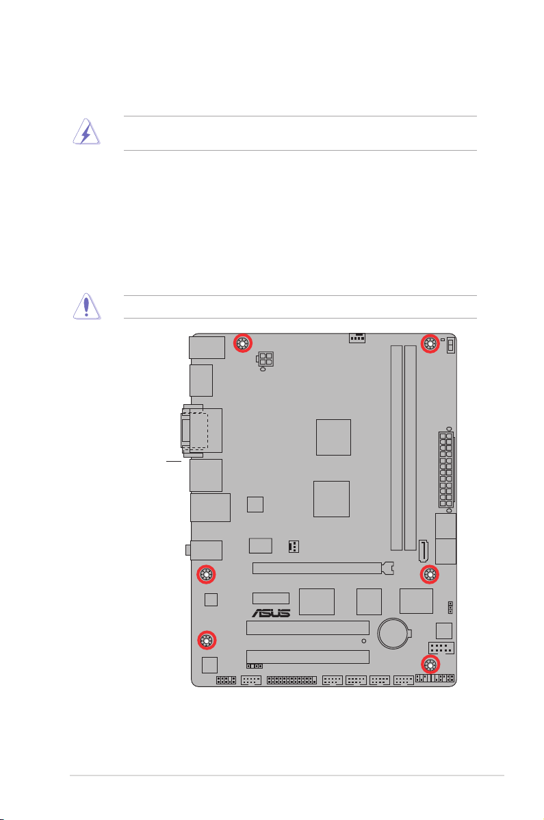
1.5.2 Screw holes
Place six screws into the holes indicated by circles to secure the motherboard to the chassis.
Do not overtighten the screws! Doing so can damage the motherboard.
Place this side towards
the rear of the chassis
1-5Chapter 1: Product introduction
E45M1-M PRO
PCIEX16
PCIEX1_1
PCI2
PCI1
LPT
COM1
USB910
USB1112
USB78
USB1314
IE1394_1
C
LR
T
C
AAFP
EATXPWR
CPU_FAN
CHA_FAN
Lithium Cell
CMOS Power
SB_PWR
Super
I/O
VIA
VT6308P
ALC
887
RTL
8111E
32Mb
BIOS
Asmedia
1042
Asmedia
ASM1083
SPDIF_OUT
18.3cm(7.2in)
24.4cm(9.6in)
DDR3 DIMM_A1 (64bit, 240-pin module)
DDR3 DIMM_A2 (64bit, 240-pin module)
SATA6G_5
SATA6G_1
SATA6G_2
SATA6G_3
SATA6G_4
PANEL
AUDIO
KB_USB56
LAN1_USB12
SPDIFO
_HDMI
F_ESATA
_USB34
DVI_VGA
ATX12V
AMD® A50M
(Hudson M1)
AMD® Dual-Core
Processor E-450
with RadeonTM
HD 6320
Discrete-Class
Graphics
TURBO_KEY_II
02LED2
ICS
9LRPS483
21 43 2 5
1
6
9
10
8
7
1113 12141516
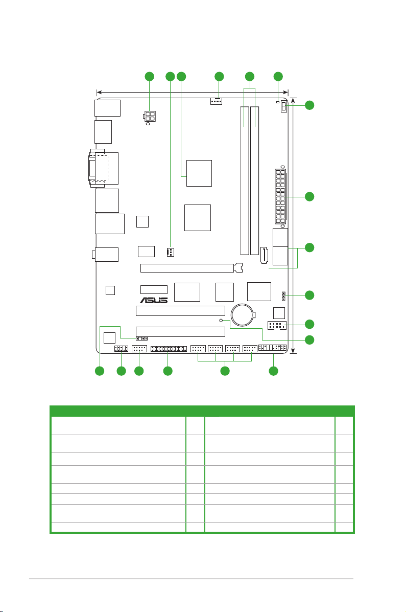
1.5.3 Motherboard layout
1.5.4 Layout contents
Connectors/Jumpers/Slots/LED Page Connectors/Jumpers/Slots/LED Page
1. ATX power connectors (24-pin EATXPWR,
4-pin ATX12V)
2. CPU and chassis fan connectors (4-pin
CPU_FAN, 3-pin CHA_FAN)
3. Integrated AMD® Dual-Core E-450 APU 1-7 11. System panel connector (20-8 pin PANEL) 1-17
4. DDR3 DIMM sockets 1-8 12. USB 2.0 connector (10-1 pin USB78,
5. Turbo Key II LED 1-21 13. LPT connector (26-1 pin LPT) 1-17
6. Turbo Key II switch 1-20 14. IEEE 1394a connector (10-1 pin IE1394_1) 1-18
7. Serial ATA 6.0Gb/s connectors (7-pin
SATA6G_1~5)
8. Clear RTC RAM (3-pin CLRTC) 1-11 16. Digital audio connector (4-1 pin SPDIF_OUT) 1-16
1-14 9. Serial port connectors (10-1 pin COM1) 1-19
1-15 10. Standby Power LED 1-21
USB910, USB1112, USB1314)
1-16 15. Front panel audio connector (10-1 pin AAFP) 1-15
ASUS E45M1-M PRO1-6
1-18
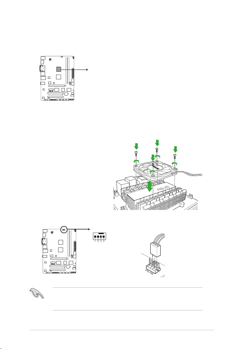
1.6 Accelerated Processing Unit (APU)
E45M1-M PRO
E45M1-M PRO Integrated AMD® Dual-Core Processor E-450
Integrated AMD® Dual-Core Processor E-450 with
AMD® RadeonTM HD 6320 Discrete-Class graphics
CPU_FAN
CPU FAN PWM
CPU FAN IN
CPU FAN PWR
GND
E45M1-M PRO
E45M1-M PRO CPU fan connector
The motherboard comes with an integrated AMD® Dual-Core Processor E-450 with AMD®
Radeon™ HD 6320 Discrete-Class graphics and a specially designed CPU heatsink.
1.6.1 Installing the CPU fan
To install the CPU fan:
1. Place the CPU fan on top of the CPU
heatsink.
2. Secure the fan on the heatsink with
the four screws.
3. Connect the CPU fan cable to the connector on the motherboard labeled CPU_FAN.
• Do not forget to connect the CPU fan connector! Hardware monitoring errors can occur
if you fail to plug this connector.
• Ensure that the CPU fan is installed properly when overclocking.
1-7Chapter 1: Product introduction
E45M1-M PRO
E45M1-M PRO 240-pin DDR3 DIMM sockets
DIMM_A1
DIMM_A2
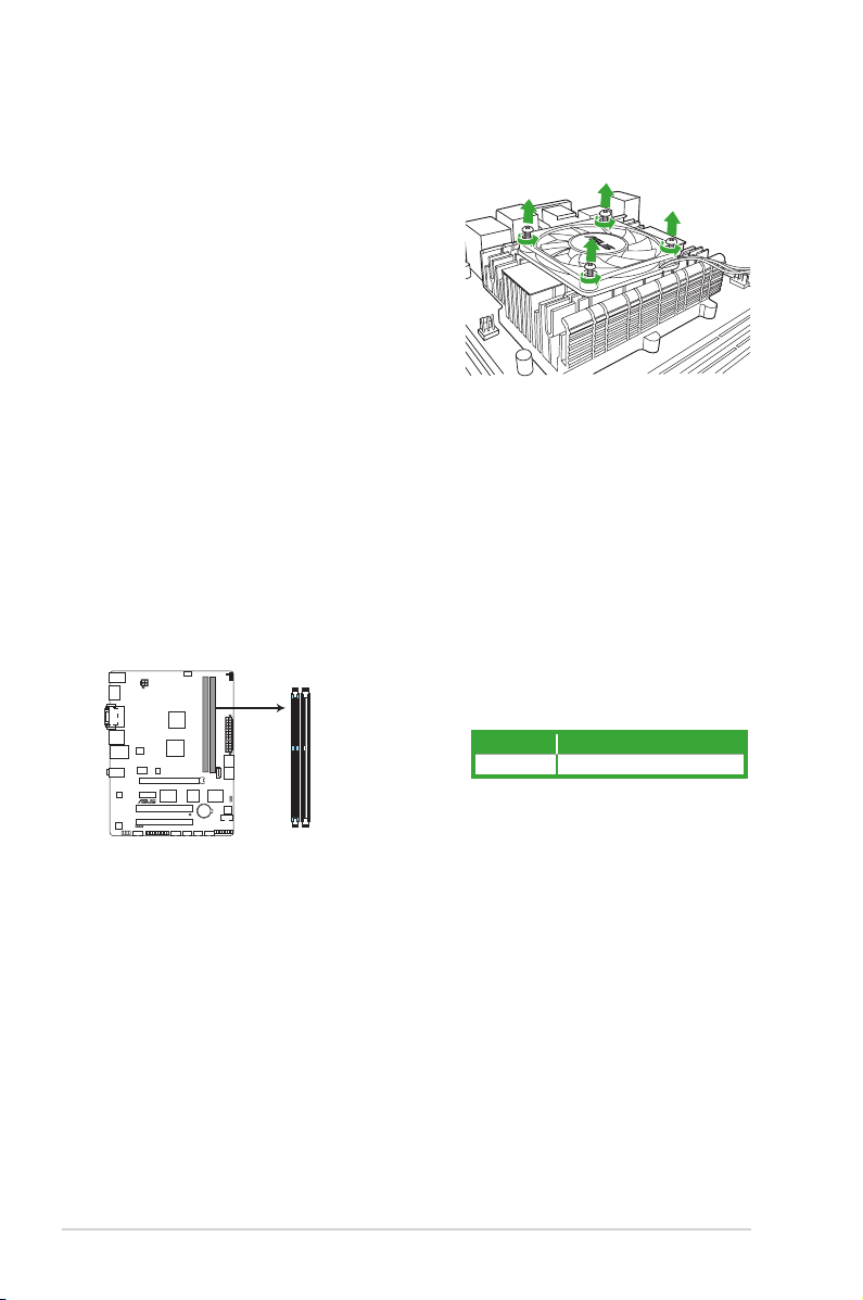
1.6.2 Uninstalling the CPU fan
To uninstall the CPU fan:
1. Disconnect the CPU fan cable from the
connector on the motherboard.
2. Remove the four screws from the CPU fan.
3. Remove the CPU fan from the CPU
heatsink.
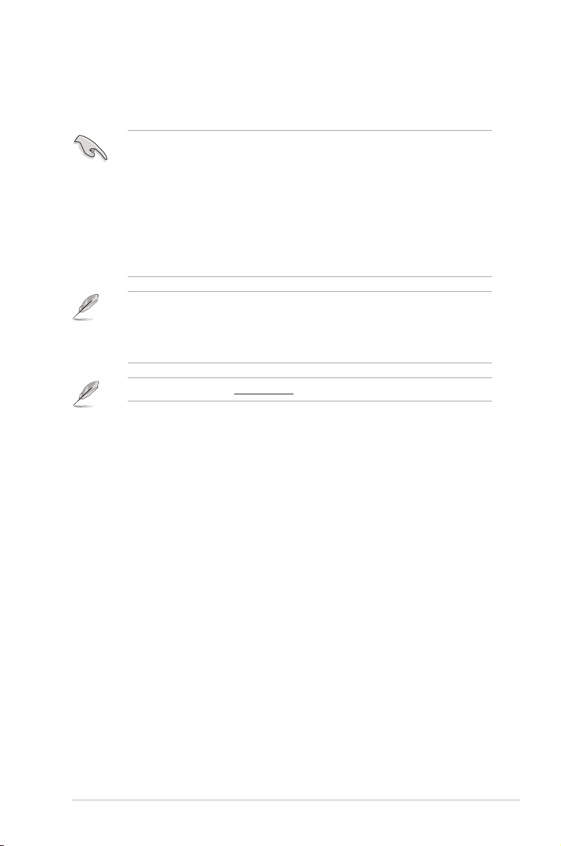
1.7 System memory
1.7.1 Overview
The motherboard comes with two Double Data Rate 3 (DDR3) Dual Inline Memory Modules
(DIMM) sockets.
A DDR3 module has the same physical dimensions as a DDR2 DIMM but is notched
differently to prevent installation on a DDR2 DIMM socket. DDR3 modules are developed for
better performance with less power consumption.
The gure illustrates the location of the DDR3 DIMM sockets:
Channel Sockets
Channel A DIMM_A1 DIMM_A2
ASUS E45M1-M PRO1-8
1.7.2 Memory congurations
You may install 1GB, 2GB, and 4GB unbuffered non-ECC DDR3 DIMMs into the DIMM
sockets.
• We recommend that you install the memory modules from the blue slots for better
overclocking capability.
• Due to the memory address limitation on 32-bit Windows® OS, when you install 4GB
or more memory on the motherboard, the actual usable memory for the OS can be
about 3GB or less. For effective use of memory, we recommend that you do any of the
following:
- Use a maximum of 3GB system memory if you are using a 32-bit Windows
- Install a 64-bit Windows® OS when you want to install 4GB or more on the
motherboard.
• This motherboard does not support DIMMs made up of 512Mb (64MB) chips or less.
The default memory operation frequency is dependent on its Serial Presence Detect (SPD),
which is the standard way of accessing information from a memory module. Under the
default state, some memory modules for overclocking may operate at a lower frequency
than the vendor-marked value. To operate at the vendor-marked or at a higher frequency,
refer to section 2.4 Ai Tweaker menu for manual memory frequency adjustment.
Visit the ASUS website at www.asus.com for the latest QVL.
®
OS.
1-9Chapter 1: Product introduction
 Loading...