

Asus E3374 User Manual

Maximus Formula
(Special Edition)/
Maximus Formula
Motherboard

E3374
First Edition V1
September 2007
Copyright © 2007 ASUSTeK COMPUTER INC. All Rights Reserved.
No part of this manual, including the products and software described in it, may be reproduced,
transmitted, transcribed, stored in a retrieval system, or translated into any language in any form or by any
means, except documentation kept by the purchaser for backup purposes, without the express written
permission of ASUSTeK COMPUTER INC. (“ASUS”).
Product warranty or service will not be extended if: (1) the product is repaired, modied or altered, unless
such repair, modication of alteration is authorized in writing by ASUS; or (2) the serial number of the
product is defaced or missing.
ASUS PROVIDES THIS MANUAL “AS IS” WITHOUT WARRANTY OF ANY KIND, EITHER EXPRESS
OR IMPLIED, INCLUDING BUT NOT LIMITED TO THE IMPLIED WARRANTIES OR CONDITIONS OF
MERCHANTABILITY OR FITNESS FOR A PARTICULAR PURPOSE. IN NO EVENT SHALL ASUS, ITS
DIRECTORS, OFFICERS, EMPLOYEES OR AGENTS BE LIABLE FOR ANY INDIRECT, SPECIAL,
INCIDENTAL, OR CONSEQUENTIAL DAMAGES (INCLUDING DAMAGES FOR LOSS OF PROFITS,
LOSS OF BUSINESS, LOSS OF USE OR DATA, INTERRUPTION OF BUSINESS AND THE LIKE),
EVEN IF ASUS HAS BEEN ADVISED OF THE POSSIBILITY OF SUCH DAMAGES ARISING FROM ANY
DEFECT OR ERROR IN THIS MANUAL OR PRODUCT.
SPECIFICATIONS AND INFORMATION CONTAINED IN THIS MANUAL ARE FURNISHED FOR
INFORMATIONAL USE ONLY, AND ARE SUBJECT TO CHANGE AT ANY TIME WITHOUT NOTICE,
AND SHOULD NOT BE CONSTRUED AS A COMMITMENT BY ASUS. ASUS ASSUMES NO
RESPONSIBILITY OR LIABILITY FOR ANY ERRORS OR INACCURACIES THAT MAY APPEAR IN THIS
MANUAL, INCLUDING THE PRODUCTS AND SOFTWARE DESCRIBED IN IT.
Products and corporate names appearing in this manual may or may not be registered trademarks or
copyrights of their respective companies, and are used only for identication or explanation and to the
owners’ benet, without intent to infringe.
ii

Contents
Contents ...................................................................................................... iii
Notices ........................................................................................................ vii
Safety information .................................................................................... viii
About this guide ......................................................................................... ix
Maximus Formula (Special Edition) / Maximus Formula specications
summary ...................................................................................................... xi
Chapter 1: Product introduction
1.1 Welcome! ...................................................................................... 1-1
1.2 Package contents .........................................................................
1.3 Special features ............................................................................
1.3.1 Product highlights ...........................................................
1.3.2 ROG Intelligent Performance & Overclocking features ...
1.3.3 ROG unique features ......................................................
1.3.4 ASUS special features ....................................................
Chapter 2: Hardware information
2.1 Before you proceed ..................................................................... 2-1
2.2 Motherboard overview .................................................................
2.2.1 Placement direction ........................................................
2.2.2 Screw holes ....................................................................
2.2.3 Motherboard layout .........................................................
2.2.4 Audio card layout ............................................................
2.2.5 Layout contents ...............................................................
2.3 Central Processing Unit (CPU) ...................................................
2.3.1 Installing the CPU ...........................................................
2.3.2 Installing the CPU heatsink and fan ...............................
2.3.3 Uninstalling the CPU heatsink and fan .........................
2.3.4 Installing the optional fans ............................................
2.4 System memory .........................................................................
2.4.1 Overview .......................................................................
2.4.2 Memory congurations ..................................................
2.4.3 Installing a DIMM ..........................................................
2.4.4 Removing a DIMM ........................................................
2.5 Expansion slots ..........................................................................
2.5.1 Installing an expansion card .........................................
1-1
1-2
1-2
1-4
1-6
1-7
2-4
2-4
2-4
2-5
2-5
2-6
2-8
2-9
2-11
2-13
2-15
2-16
2-16
2-17
2-20
2-20
2-21
2-21
iii

Contents
2.5.2 Conguring an expansion card ..................................... 2-21
2.5.3 Interrupt assignments ...................................................
2.5.4 PCI slots ........................................................................
2.5.5 PCI Express x1 slots .....................................................
2.5.6 PCI Express x16 slots ...................................................
2.6 Switch ..........................................................................................
2.7 Audio card, I/O shield, and LCD Poster installation ...............
2.7.1 Audio card Installation ...................................................
2.7.2 I/O shield and LCD Poster Installation ..........................
2.8 Connectors .................................................................................
2.8.1 Rear panel connectors ..................................................
2.8.2 Internal connectors .......................................................
2.8.3 Onboard switches .........................................................
2.8.4 Installing Fusion Block System accessory ....................
Chapter 3: Powering up
3.1 Starting up for the rst time ........................................................ 3-1
3.2 Turning off the computer .............................................................
3.2.1 Using the OS shut down function ....................................
3.2.2 Using the dual function power switch ..............................
2-22
2-23
2-23
2-23
2-24
2-25
2-25
2-26
2-27
2-27
2-29
2-38
2-39
3-2
3-2
3-2
Chapter 4: BIOS setup
4.1 Managing and updating your BIOS ............................................ 4-1
4.1.1 ASUS Update utility ........................................................
4.1.2 Creating a bootable oppy disk .......................................
4.1.3 ASUS EZ Flash 2 utility ...................................................
4.1.4 AFUDOS utility ................................................................
4.1.5 ASUS CrashFree BIOS 3 utility ......................................
4.2 BIOS setup program ....................................................................
4.2.1 BIOS menu screen ........................................................
4.2.2 Menu bar .......................................................................
4.2.3 Navigation keys .............................................................
4.2.4 Menu items ....................................................................
4.2.5 Sub-menu items .............................................................
4.2.6 Conguration elds ........................................................
4.2.7 Pop-up window ..............................................................
iv
4-1
4-4
4-5
4-6
4-8
4-9
4-10
4-10
4-10
4-11
4-11
4-11
4-11

Contents
4.2.8 Scroll bar ........................................................................4-11
4.2.9 General help ..................................................................
4.3 Main menu ..................................................................................
4.3.1 System Time .................................................................
4.3.2 System Date .................................................................
4.3.3 Legacy Diskette A .........................................................
4.3.4 Language ......................................................................
4.3.5
4.3.6 SATA Conguration .......................................................
4.3.7 AHCI Conguration .......................................................
4.3.8 System Information .......................................................
4.4 Extreme Tweaker menu .............................................................
4.4.1 Congure System Performance Settings ......................
Advanced menu ......................................................................... 4-23
4.5
4.5.1 CPU Conguration ........................................................
4.5.2 Chipset ..........................................................................
4.5.3 OnBoard Devices Conguration ...................................
4.5.4 USB Conguration ........................................................
4.5.5 PCI PnP ........................................................................
4.6 Power menu ................................................................................
4.6.1 Suspend Mode ..............................................................
4.6.2 Repost Video on S3 Resume ........................................
4.6.3 ACPI Version .................................................................
4.6.4 ACPI APIC Support .......................................................
4.6.5 APM Conguration ........................................................
4.6.6 Hardware Monitor .........................................................
4.7 Boot menu ..................................................................................
4.7.1 Boot Device Priority ......................................................
4.7.2 Boot Settings Conguration ..........................................
4.7.3 Security .........................................................................
4.8 Tools menu .................................................................................
4.8.1 ASUS EZ Flash 2 ..........................................................
4.8.2 ASUS O.C. Prole .........................................................
4.8.3 AI Net 2 .........................................................................
4.9 Exit menu ....................................................................................
SATA 1-6 ..........................................................................................4-13
4-11
4-12
4-12
4-12
4-12
4-12
4-14
4-15
4-16
4-17
4-17
4-24
4-25
4-26
4-27
4-28
4-29
4-29
4-29
4-29
4-29
4-30
4-31
4-34
4-34
4-35
4-36
4-38
4-38
4-39
4-40
4-41
v

Contents
Chapter 5: Software support
5.1 Installing an operating system ................................................... 5-1
5.2 Support DVD information ............................................................
5.2.1 Running the support DVD ...............................................
5.2.2 Drivers menu ...................................................................
5.2.3 Utilities menu ..................................................................
5.2.4 Make Disk menu .............................................................
5.2.5 Manuals menu ................................................................
5.2.6 Video menu .....................................................................
5.2.7 ASUS Contact information ..............................................
5.2.8 Other information ............................................................
5.3 Software information ...................................................................
™
5.3.1 ASUS MyLogo 3
5.3.2 AI NET 2
.........................................................................5-11
5.3.3 AI Audio 2 (SoundMAX
5.3.4 ASUS PC Probe II .........................................................
5.3.5 ASUS AI Suite ...............................................................
5.3.6 ASUS EPU Utility—AI Gear 3 .......................................
5.3.7 ASUS AI Nap ................................................................
5.3.8 ASUS Q-Fan 2 ..............................................................
5.3.9 ASUS AI Booster ...........................................................
5.4 RAID congurations ..................................................................
5.4.1 RAID denitions ............................................................
5.4.2 Installing Serial ATA hard disks .....................................
®
5.4.3 Intel
RAID congurations ............................................. 5-34
5.5 Creating a RAID driver disk .......................................................
5.5.1 Creating a RAID driver disk without entering the OS ....
5.5.2 Creating a RAID/SATA driver disk in Windows
........................................................... 5-9
®
High Denition Audio utility) ... 5-12
®
............ 5-42
5-1
5-1
5-2
5-3
5-5
5-6
5-6
5-7
5-7
5-9
5-21
5-27
5-29
5-30
5-31
5-32
5-33
5-33
5-34
5-42
5-42
Appendix: CPU features
A.1 Intel® EM64T ..................................................................................A-1
®
A.2 Enhanced Intel SpeedStep
A.2.1 System requirements ......................................................
A.2.2 Using the EIST ................................................................
®
A.3 Intel
Hyper-Threading Technology ...........................................A-3
Using the Hyper-Threading Technology ........................................ A-3
A.4 Debug Code Table ........................................................................
vi
Technology (EIST) ........................A-1
A-1
A-2
A-4

Notices
Federal Communications Commission Statement
This device complies with Part 15 of the FCC Rules. Operation is subject to the
following two conditions:
•
This device may not cause harmful interference, and
•
This device must accept any interference received including interference that
may cause undesired operation.
This equipment has been tested and found to comply with the limits for a
Class B digital device, pursuant to Part 15 of the FCC Rules. These limits are
designed to provide reasonable protection against harmful interference in a
residential installation. This equipment generates, uses and can radiate radio
frequency energy and, if not installed and used in accordance with manufacturer’s
instructions, may cause harmful interference to radio communications. However,
there is no guarantee that interference will not occur in a particular installation. If
this equipment does cause harmful interference to radio or television reception,
which can be determined by turning the equipment off and on, the user is
encouraged to try to correct the interference by one or more of the following
measures:
•
Reorient or relocate the receiving antenna.
•
Increase the separation between the equipment and receiver.
•
Connect the equipment to an outlet on a circuit different from that to which the
receiver is connected.
•
Consult the dealer or an experienced radio/TV technician for help.
The use of shielded cables for connection of the monitor to the graphics card is
required to assure compliance with FCC regulations. Changes or modications
to this unit not expressly approved by the party responsible for compliance
could void the user’s authority to operate this equipment.
Canadian Department of Communications Statement
This digital apparatus does not exceed the Class B limits for radio noise emissions
from digital apparatus set out in the Radio Interference Regulations of the
Canadian Department of Communications.
This class B digital apparatus complies with Canadian ICES-003.
vii

Safety information
Electrical safety
•
To prevent electrical shock hazard, disconnect the power cable from the
electrical outlet before relocating the system.
•
When adding or removing devices to or from the system, ensure that the
power cables for the devices are unplugged before the signal cables are
connected. If possible, disconnect all power cables from the existing system
before you add a device.
•
Before connecting or removing signal cables from the motherboard, ensure
that all power cables are unplugged.
•
Seek professional assistance before using an adpater or extension cord.
These devices could interrupt the grounding circuit.
•
Make sure that your power supply is set to the correct voltage in your area.
If you are not sure about the voltage of the electrical outlet you are using,
contact your local power company.
•
If the power supply is broken, do not try to x it by yourself. Contact a
qualied service technician or your retailer.
Operation safety
•
Before installing the motherboard and adding devices on it, carefully read all
the manuals that came with the package.
•
Before using the product, make sure all cables are correctly connected and the
power cables are not damaged. If you detect any damage, contact your dealer
immediately.
•
To avoid short circuits, keep paper clips, screws, and staples away from
connectors, slots, sockets and circuitry.
•
Avoid dust, humidity, and temperature extremes. Do not place the product in
any area where it may become wet.
•
Place the product on a stable surface.
•
If you encounter technical problems with the product, contact a qualied
service technician or your retailer.
viii
This symbol of the crossed out wheeled bin indicates that the product (electrical
and electronic equipment, and mercury-containing button cell battery) should
not be placed in municipal waste. Check local regulations for disposal of
electronic products.

About this guide
This user guide contains the information you need when installing and conguring
the motherboard.
How this guide is organized
This guide contains the following parts:
• Chapter 1: Product introduction
This chapter describes the features of the motherboard and the new
technology it supports.
• Chapter 2: Hardware information
This chapter lists the hardware setup procedures that you have to perform
when installing system components. It includes description of the switches,
jumpers, and connectors on the motherboard.
• Chapter 3: Powering up
This chapter describes the power up sequence and ways of shutting down
the system.
• Chapter 4: BIOS setup
This chapter tells how to change system settings through the BIOS Setup
menus. Detailed descriptions of the BIOS parameters are also provided.
• Chapter 5: Software support
This chapter describes the contents of the support DVD that comes with the
motherboard package and the software.
• Appendix: CPU features
The Appendix describes the CPU features and technologies that the
motherboard supports as well as the debug code table for the LCD Poster.
Where to nd more information
Refer to the following sources for additional information and for product and
software updates.
1. ASUS websites
The ASUS website provides updated information on ASUS hardware and
software products. Refer to the ASUS contact information.
2. Optional documentation
Your product package may include optional documentation, such as warranty
yers, that may have been added by your dealer. These documents are not
part of the standard package.
ix

Conventions used in this guide
To make sure that you perform certain tasks properly, take note of the following
symbols used throughout this manual.
DANGER/WARNING: Information to prevent injury to yourself
when trying to complete a task.
CAUTION: Information to prevent damage to the components
when trying to complete a task.
IMPORTANT: Instructions that you MUST follow to complete a
task.
NOTE: Tips and additional information to help you complete a
task.
Typography
Bold text Indicates a menu or an item to select.
Italics
Used to emphasize a word or a phrase.
<Key> Keys enclosed in the less-than and greater-than sign
means that you must press the enclosed key.
Example: <Enter> means that you must press the
Enter or Return key.
<Key1+Key2+Key3> If you must press two or more keys simultaneously, the
key names are linked with a plus sign (+).
Example: <Ctrl+Alt+D>
Command Means that you must type the command exactly as
shown, then supply the required item or value enclosed
in brackets.
Example: At the DOS prompt, type the command line:
afudos /i[lename]
afudos /iFormula.ROM
x

Maximus Formula (Special Edition) /
Maximus Formula specications summary
CPU LGA775 socket for Intel® Core™2 Quad /
Chipset Intel® X38 / ICH9R with Intel® Fast Memory Access
System Bus 1333/1066/800 MHz
Memory Dual-channel memory architecture
Expansion Slots 2 x PCIe x16 slots (@ full x16, x16 speed)
CrossFire™ Technology Supports ATI CrossFire™ graphics cards
Storage Southbridge
LAN Dual Gigabit LAN controllers, both featuring AI NET 2
High Denition Audio SupremeFX II Audio Card
IEEE 1394 2 x IEEE 1394a ports (one at midboard; one at back
USB 12 x USB 2.0 ports (6 ports at midboard, 6 ports at back
Core™2 Extreme / Core™2 Duo / Pentium® Extreme /
Pentium® D / Pentium® 4 processors
Supports Intel® next-generation 45nm multi-core CPUs
Compatible with Intel® 06/05B/05A processors
* Refer to www.asus.com for Intel CPU support list
Technology
- 4 x 240-pin DIMM sockets support unbuffered ECC /
non-ECC DDR2 1066*/800/667MHz memory
modules
- Supports up to 8 GB system memory
* The chipset ofcially supports the memory frequency up
to DDR2 800MHz. Tuned by the ASUS Super Memspeed
Technology, this motherboard natively supports up to
DDR2 1066MHz.
Refer to www.asus.com or this user manual for the
Memory QVL (Qualied Vendors Lists).
3 x PCIe x1 (PCIEX1_1 (black) is compatible with the
audio slot.)
2 x PCI 2.2 slots
- 6 x SATA 3.0 Gb/s ports
- Intel® Matrix Storage Technology supports RAID 0,
1, 5, and 10
JMicron® JMB368 PATA controller
- 1 x UltraDMA 133/100/66 for up to 2 PATA devices
Supports Teaming Technology
- ADI 1988B 8-channel High Denition Audio CODEC
- Noise Filter
Coaxial / Optical S/PDIF Out ports at back I/O
panel)
panel)
(continued on the next page)
xi
Maximus Formula (Special Edition) /
Maximus Formula specications summary
ROG Exclusive
Overclocking features
ROG Special Features LCD Poster
Back Panel I/O Ports 1 x PS/2 Keyboard (purple)
Internal I/O Connectors 3 x USB connectors support additional 6 USB ports
Fusion Block System
Extreme Tweaker
2-Phase DDR2
Loadline Calibration
Intelligent overclocking tools:
- CPU Level Up
- AI Gear 3
- AI Overclocking (intelligent CPU frequency tuner)
- AI Booster Utility
- O.C. Prole
Overclocking protection:
- COP EX (Component Overheat Protection -EX)
- Voltiminder LED
- ASUS C.P.R. (CPU Parameter Recall)
Onboard Switches: Power / Reset / Clr CMOS (at rear
panel)
ASUS Q-Connector
ASUS Q-Fan 2
ASUS EZ Flash 2
ASUS CrashFree BIOS 3
ASUS MyLogo 3™
1 x S/PDIF Out (Coaxial + Optical)
1 x IEEE1394a port
2 x LAN (RJ45) ports
6 x USB 2.0/1.1 ports
1 x Clr CMOS switch
1 x Floppy disk drive connector
1 x IDE connector for two devices
6 x SATA connectors
8 x Fan connectors (1 x CPU / 1 x Power / 3 x Chassis /
3 x Optional)
3 x Thermal sensor connectors
1 x IEEE1394a connector
1 x S/PDIF Out connector
1 x Chassis Intrusion connector
24-pin ATX Power connector
8-pin ATX 12V Power connector
1 x En/Dis-able Clr CMOS
1 x LCD Poster connector
1 x System panel connector
1 x Power-on switch
1 x Reset switch
(for Special Edition only)
(continued on the next page)
xii
Maximus Formula (Special Edition) /
Maximus Formula specications summary
BIOS Features 16 Mb Flash ROM, AMI BIOS, PnP, DMI2.0, WfM2.0,
Manageability WOL by PME, WOR by PME, Chassis Intrusion, PXE
Accessories Fusion Block System Accessory
Software The hottest 3D game: S.T.A.L.K.E.R.
Form Factor ATX Form Factor, 12”x 9.6” (30.5 cm x 24.4 cm)
*Specications are subject to change without notice.
SM BIOS 2.4, ACPI 2.0a Multi-Language BIOS
(for Special Edition only)
LCD Poster
ASUS Optional Fan
SupremeFX II Audio Card
3 in 1 ASUS Q-connector kit
UltraDMA 133/100/66 cable
Floppy disk drive cable
Serial ATA cables
Serial ATA power cables
2-port USB2.0 + IEEE 1394a module
I/O Shield
Cable ties
User's manual
Support DVD:
Drivers
ASUS PC Probe II
ASUS Update
ASUS AI Suite
Futuremark® 3DMark® 06 Advanced Edition
Kaspersky® Anti-virus software
xiii

xiv

This chapter describes the motherboard
features and the new technologies
it supports.
Product
1
introduction

Chapter summary
1
1.1 Welcome! ...................................................................................... 1-1
1.2 Package contents .........................................................................
1.3 Special features ............................................................................
1-1
1-2
ROG Maximus Formula (Special Edition) / Maximus Formula

1.1 Welcome!
Thank you for buying an ASUS® Maximus Formula (Special Edition) / Maximus
Formula motherboard!
The motherboard delivers a host of new features and latest technologies, making it
another standout in the long line of ASUS quality motherboards!
Before you start installing the motherboard, and hardware devices on it, check the
items in your package with the list below.
1.2 Package contents
Check your motherboard package for the following items.
Motherboard ROG Maximus Formula (Special Edition) /
Maximus Formula
I/O module USB 2.0 + IEEE 1394a module
Cables Ultra DMA 133/100/66 cable
Floppy disk drive cable
Serial ATA cables
Serial ATA power cables
Accessories I/O shield
ASUS Optional Fan
Fusion Block System Accessory (for Special Edition
only)
LCD Poster
SupremeFX II Audio Card
3-in-1 ASUS Q-Connector Kit
Cable ties
Application DVD/CD ROG motherboard support DVD
The hottest game: S.T.A.L.K.E.R.
Documentation User guide
If any of the above items is damaged or missing, contact your retailer.
ROG Maximus Formula (Special Edition) / Maximus Formula 1-1
1.3 Special features
1.3.1 Product highlights
Republic of Gamers
The Republic of Gamers consists only the best of the best. We offer the best
hardware engineering, the fastest performance, the most innovating ideas, and we
welcome the best gamers to join in. In the Republic of Gamers, mercy rules are
only for the weak, and bragging rights means everything. We believe in making
statements and we excel in competitions. If your character matches our trait, then
join the elite club, make your presence felt, in the Republic of Gamers.
Intel® Quad-core Processor ready
This motherboard supports the latest Intel® Quad-core processors in the LGA775
package and Intel’s next-generation 45nm multi-core processors. It is excellent for
multi-tasking, multi-media and enthusiastic gamers with 1333/1066/800 MHz FSB.
Intel® Quad-core processor is one of the most powerful CPU in the world. See
page 2-8 for details.
Intel® Core™2 Duo/ Intel® Core™2 Extreme CPU support
This motherboard supports the latest Intel® Core™2 processor in the LGA775
package and Intel’s next-generation 45nm multi-core processors. With the new
Intel® Core™ microarchitecture technology and 1333/1066/800 MHz FSB, the
Intel® Core™2 is one of the most powerful and energy efcient CPUs in the world.
See page 2-8 for details.
Intel® X38 Chipset
The Intel® X38 Express Chipset is the latest chipset designed to support 8GB of
dual-channel DDR2 1066/800/677 architecture, 1333/1066/800 FSB (Front Side
Bus), dual PCI Express 2.0 x16 graphics, and multi-core CPUs. With the specially
included Intel® Fast Memory Access technology, available memory bandwidth
usage is optimized and memory access latency is reduced—allowing faster
memory speed.
ATI CrossFire™ Technology
ATI’s CrossFire™ boosts image quality along with rendering speed, eliminating
the need to scale down screen resolution to get high quality images. CrossFire™
allows higher antialiasing, anisotropic ltering, shading, and texture settings. Adjust
your display congurations, experiment with the advanced 3D settings, and check
the effects with a real-time 3D-rendered previews within ATI Catalyst™ Control
Center.
1-2 Chapter 1: Product Introduction

Native DDR2 1066 memory support
To attain top performance, ASUS engineers have successfully unleashed the
true potential of DDR2 memory. While in DDR2 1066 mode, ASUS’s exclusive
technology offers a choice of FSB 1333, providing great performance for 3D
graphics and other memory demanding applications. See page 2-16 for details.
Dual-channel DDR2 800 memory support
The motherboard supports DDR2 memory that features data transfer rates of
800/667 MHz to meet the higher bandwidth requirements of the latest 3D graphics,
multimedia, and Internet applications. The dual-channel DDR2 architecture
doubles the bandwidth of your system memory to boost system performance,
eliminating bottlenecks with peak bandwidths of up to 12.8 GB/s. Furthermore, this
motherboard does not restrict the memory size across two channels. Users may
install different memory size DIMMs into the two channels and enjoy dual-channel
and single-channel functions at the same time. This new feature optimizes the use
of available memory size. See page 2-16 for details.
ASUS Super Memspeed Technology
To attain top performance, ASUS has managed to break through current FSB
and DRAM ratio proportions by utilizing Super Memspeed Technology–the latest
technology that provides even more precise overclocking options to unleash the
true potential of DDR2 memory. The DDR2 Mode maximizes system performance
by eliminating the bottleneck when overclocking both the CPU and memory–
providing great performance for 3D graphics and other memory demanding
applications. See page 2-16 for details.
Serial ATA 3.0 Gb/s technology
This motherboard supports the next-generation hard drives based on the Serial
ATA (SATA) 3Gb/s storage specication, delivering enhanced scalability and
doubling the bus bandwidth for high-speed data retrieval and saves. See page
2-30 for details.
Dual Gigabit LAN
The integrated dual Gigabit LAN design allows a PC to serve as a network
gateway for managing trafc between two separate networks. This capability
ensures rapid transfer of data from WAN to LAN without any added arbitration or
latency. See page 2-27 for details.
ROG Maximus Formula (Special Edition) / Maximus Formula 1-3

IEEE 1394a support
The IEEE 1394a interface provides high speed digital interface for audio/video
appliances such as digital television, digital video camcorders, storage peripherals
& other PC portable devices. See pages 2-28 and 2-32 for details.
High Denition Audio
Enjoy high-end sound quality on your PC! The onboard 8-channel HD audio (High
Denition Audio, previously codenamed Azalia) CODEC enables high-quality
192KHz/24-bit audio output, jack-sensing feature, retasking functions, and multi-
streaming technology that simultaneously sends different audio streams to different
destinations. You can now talk to your partners on the headphones while playing
multi-channel network games. See pages 2-28 for details.
Green ASUS
This motherboard and its packaging comply with the European Union’s Restriction
on the use of Hazardous Substances (RoHS). This is in line with the ASUS vision
of creating environment-friendly and recyclable products/packaging to safeguard
consumers’ health while minimizing the impact on the environment.
1.3.2 ROG Intelligent Performance & Overclocking features
Fusion Block System
The Fusion Block System is a more efcient thermal solution compared to
competing followers with complicated looks. It is a hybrid thermal design that
combines the ROG’s renowned heatpipe design with the additional ability to
connect to a water cooling system. By taking the entire integrated solution into
design considerations, the user can enjoy exceptional thermal improvement
to the northbridge and southbridge with a single connection. The Fusion Block
System is the most veratile, efcient, and advanced thermal system there is on a
motherboard.
(for Special Edition only)
CPU Level Up
Ever wish that you could have a more expansive CPU? Upgrade your CPU at no
additional cost with ROG’s CPU Level Up! Simply choose a processor you want to
OC to, and the motherboard will do the rest for you. See the new CPU speed and
enjoy the performance instantly! Overclocking is never as easy as this. See pages
4-17 and 4-18 for details.
1-4 Chapter 1: Product Introduction
ASUS EPU
The ASUS EPU utilizes innovative technology to digitally monitor and tune the
CPU power supply with improved VR responses in heavy or light loadings. It
automatically provides power for higher performance or improve efciency by 7%
when the PC is running low intensity applications. Working together with AI Gear 3,
this can help you attain the best possible power efciency and energy savings up
to 20% to help save the environment. See page 5-29 for details.
2-Phase DDR2
With the embedded 2-Phase DDR2, this motherboard allows users to reach higher
memory frequencies and enjoy better performance. Compared with only one phase
solutions, this motherboard ensures longer power component lifespans and higher
overclockability due to cooler temperatures and better efciency.
Extreme Tweaker
Extreme Tweaker is the one stop shop to ne-tune your system to optimal
performance. No matter if you are looking for frequency adjustment, over-voltage
options, or memory timing settings, they are all here! See page 4-17 for details.
Voltiminder LED
In the persuit of extreme performance, overvoltage adjustment is critical but risky.
Acting as the “red zone” of a tachometer, the Voltiminder LED displays the voltage
status for CPU, NB, SB, and Memory in a intuitive color-coded fashion. The
Voltiminder LED allows quick voltage monitoring for overclockers. See pages 2-1
to 2-3 for details.
Component Overheat Protection -EX (COP EX)
The COP EX allows overclockers to increase chipset voltages without the worries
of overheating. It can also be used to monitor and save an overheating GPU.
The COP EX allows more freedom and less constraint for maximum performance
achievement.
AI Booster
The ASUS AI Booster allows you to overclock the CPU speed in Windows
environment without the hassle of booting the BIOS. See page 5-32 for details.
ASUS O.C. Prole
The motherboard features the ASUS O.C. Prole that allows users to conveniently
store or load multiple BIOS settings. The BIOS settings can be stored in the
CMOS or a separate le, giving users freedom to share and distribute their favorite
settings. See page 4-39 for details.
ROG Maximus Formula (Special Edition) / Maximus Formula 1-5

C.P.R. (CPU Parameter Recall)
When the system hangs due to overclocking failure, there is no need to open the
system chassis to clear CMOS data. Simply reboot the system, and the BIOS
automatically restores the CPU default settings for each parameter.
Due to the chipset behavior, AC power off is required before using C.P.R.
function.
1.3.3 ROG unique features
Supreme FX II features
Supreme FX II delivers an excellent high denition audio experience to the gamers
of ROG. The SupremeFX II features unique audio innovations for gamers to spot
enemies in 3D environment during game play. SupremeFX II also provides a
special tool to emphasize human voices in games to help make dialogues clearer.
Noise Filter
This feature detects repetitive and stationary noises (non-voice signals) like
computer fans, air conditioners, and other background noises then eliminates
it in the incoming audio stream while recording.
External LCD Poster
The new LCD Poster now posts critical POST information in an ever friendly
and exible external display. When system malfunction occurs, the LCD Poster
automatically detects device failure and translates the errors on the LCD during
POST. Unlike other competing 2 digit displays, users do not need to read
“gibberish” to nd out what is wrong. See page 2-26 for details.
Onboard Switches
With an easy press during overclocking, this exclusive onboard switch allows
gamers to effortlessly ne-tune the performance without having to short the pins or
moving jumpers. See page 2-38 for details.
ASUS Quiet Thermal Solution
ASUS Quiet Thermal solution makes system more stable and enhances the
overclocking capability.
1-6 Chapter 1: Product Introduction
Fanless Design–Heat-pipe
The ASUS fanless design allows multi-directional heat ow from major
thermal sources in the motherboard to lower overall system temperature,
resulting in quieter operation and longer system life. ASUS has devoted
special efforts to address the thermal issues across the motherboard, and
most notably in the following areas: CPU, power, VGA, Northbridge and
Southbridge. The heat pipe, heatsink, and strategic board layout were tailor
made to dissipate heat in the most efcient manner.
Fanless Design–Stack Cool 2
ASUS Stack Cool 2 is a fan-less and zero-noise cooling solution that lowers
the temperature of critical heat generating components. The motherboard
uses a special design on the printed circuit board (PCB) to dissipate heat
these critical components generate.
1.3.4 ASUS special features
AI Gear 3
With a manual or automatic mode, AI Gear 3 allows users to choose from
four proles to adjust CPU frequency and vCore voltage—“Turbo Mode,”
“High Performance Mode,” “Medium Power Saving Mode,” and “Max Power
Saving Mode.” As a digital solution, AI Gear 3 is very precise and can
automatically detect current CPU loading, dynamically overclocking the CPU
speed in real time and lowering the voltage for power saving during light
loading. With this power saving mode, users can make real-time changes in
the operating system and can save up to 62% CPU power in light loading.
See page 5-29 for details.
AI Nap
With AI Nap, the system can continue running at minimum power and noise
when you are temporarily away. To wake the system and return to the OS
environment, simply click the mouse or press a key. See page 5-30 for
details.
ASUS Q-Fan 2
ASUS Q-Fan 2 technology intelligently adjusts both CPU fan and chassis fan
speeds according to system loading to ensure quiet, cool and efcient operation.
See pages 4-31, 4-32, and 5-31 for details.
ROG Maximus Formula (Special Edition) / Maximus Formula 1-7
Optional Fan
The optional fan is specically designed to provide sufcient airow over the
CPU power modules and chipset area when water-cooling or passive-cooling
is utilized, ensuring effective heat dissipation for the entire system. See
pages 2-15 and 2-33 for details.
ASUS MyLogo 3
ASUS MyLogo 3 is a new feature present in the motherboard that allows you
to personalize and add style to your system with customizable and animated
boot logos. See page 5-9 for details.
ASUS Multi-language BIOS
The multi-language BIOS allows you to select the language of your choice
from the available options. The localized BIOS menus allow easier and faster
conguration. See page 4-12 for details.
(for water-cooling/passive-cooling only)
ASUS EZ DIY
ASUS EZ DIY feature collection provides you easy ways to install computer
components, update the BIOS or back up your favorite settings.
ASUS Q-Connector
The ASUS Q-Connector allows you to connect or disconnect chassis front
panel cables in one easy step with one complete module. This unique
adapter eliminates the trouble of plugging in one cable at a time, making
connection quick and accurate. See pages 2-37 for details.
ASUS EZ Flash 2
EZ Flash 2 is a user-friendly BIOS update utility. Simply launch this tool and
update BIOS using a USB ash disk without entering the OS. You can update
your BIOS in a few clicks without preparing an additional oppy diskette or
using an OS-based ash utility. See pages 4-5 and 4-38 for details.
ASUS CrashFree BIOS 3
The ASUS CrashFree BIOS 3 allows users to restore corrupted BIOS data
from a USB ash disk containing the BIOS le. See page 4-8 for details.
1-8 Chapter 1: Product Introduction

This chapter lists the hardware setup
procedures that you have to perform
when installing system components. It
includes description of the jumpers and
connectors on the motherboard.
information
Hardware
2

Chapter summary
2
2.1 Before you proceed ..................................................................... 2-1
2.2 Motherboard overview .................................................................
2.3 Central Processing Unit (CPU) ...................................................
2.4 System memory .........................................................................
2.5 Expansion slots ..........................................................................
2.6 Switch ..........................................................................................
2.7 Aduio card, I/O shield, and LCD Poster Installation ...............
2.8 Connectors .................................................................................
2-4
2-8
2-16
2-21
2-22
2-25
2-27
ROG Maximus Formula (Special Edition) / Maximus Formula
2.1 Before you proceed
MAXIMUS FORMULA
®
MAXIMUS FORMULA(Special Edition)/
MAXIMUS FORMULA CPU LED
CPU_CRAZY
CPU_HIGH
CPU_NORMAL
Take note of the following precautions before you install motherboard components
or change any motherboard settings.
• Unplug the power cord from the wall socket before touching any
component.
• Use a grounded wrist strap or touch a safely grounded object or a metal
object, such as the power supply case, before handling components to
avoid damaging them due to static electricity.
• Hold components by the edges to avoid touching the ICs on them.
• Whenever you uninstall any component, place it on a grounded antistatic
pad or in the bag that came with the component.
• Before you install or remove any component, ensurethat the ATX power
supply is switched off or the power cord is detached from the power
supply. Failure to do so may cause severe damage to the motherboard,
peripherals, and/or components.
Onboard LEDs
The motherboard comes with LEDs that indicate the voltage conditions of CPU,
memory, northbridge, and southbridge. You may adjust the voltages in BIOS. There
are also an LED for hard disk drive activity and an onboard switch for power status.
For more information about voltage adjustment, refer to 4.4 Extreme Tweaker
menu.
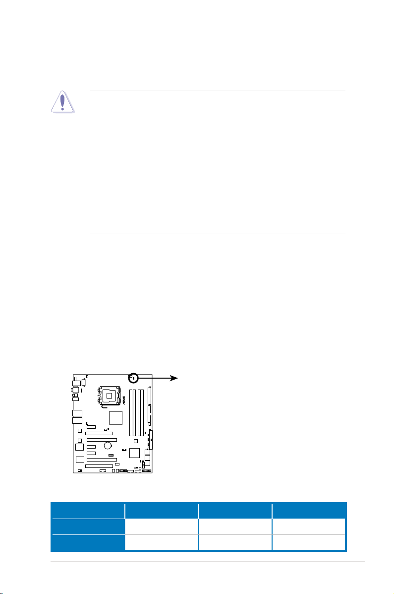
1. CPU LED
The CPU LED has two voltage displays: CPU Voltage and CPU PLL Voltage;
you can select the voltage to display in BIOS. Refer to the illustration below
for the location of the CPU LED and the table below for LED denition.
Normal (green) High (yellow) Crazy (red)
CPU Voltage
CPU PLL Voltage
1.10000~1.50000 1.50625~1.69375 1.70000~
1.50000~1.60000 1.62000~1.80000 1.82000~
ROG Maximus Formula (Special Edition) / Maximus Formula 2-1
2. Memory LED
MAXIMUS FORMULA
®
MAXIMUS FORMULA(Special Edition)/
MAXIMUS FORMULA DDR LED
DDR_CRAZY
DDR_HIGH
DDR_NORMAL
MAXIMUS FORMULA
®
MAXIMUS FORMULA(Special Edition)/
MAXIMUS FORMULA North/South Bridge LED
NB_CRAZY
NB_HIGH
NB_NORMAL
SB_CRAZY
SB_HIGH
SB_NORMAL
Refer to the illustration below for the location of the memory LED and the
table below for LED denition.
Normal (green) High (yellow) Crazy (red)
DRAM Voltage
1.80~2.20 2.22~2.60 2.62~
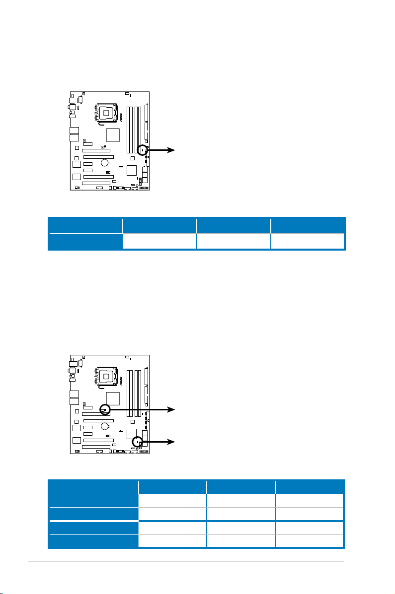
3. Northbridge/Southbridge LEDs
The northbridge and southbridge LEDs each have two different voltage
displays. The northbridge LED displays either the North Bridge Voltage or
the FSB Termination Voltage. The southbridge LED shows either the South
Bridge Voltage or the SB 1.5V Voltage. You can select the voltage to display
in BIOS. Refer to the illustration below for the location of the northbridge/
southbridge LEDs and the table below for LED denition.
North Bridge Voltage
FSB Termination Voltage
South Bridge Voltage
SB 1.5V Voltage
2-2 Chapter 2: Hardware information
Normal (green) High (yellow) Crazy (red)
1.25~1.49 1.51~1.73 1.73~
1.20~1.40 1.42~1.60 1.62~
1.050~1.125 1.150~1.175 1.200~
1.50~1.60 1.65~1.85 1.90~
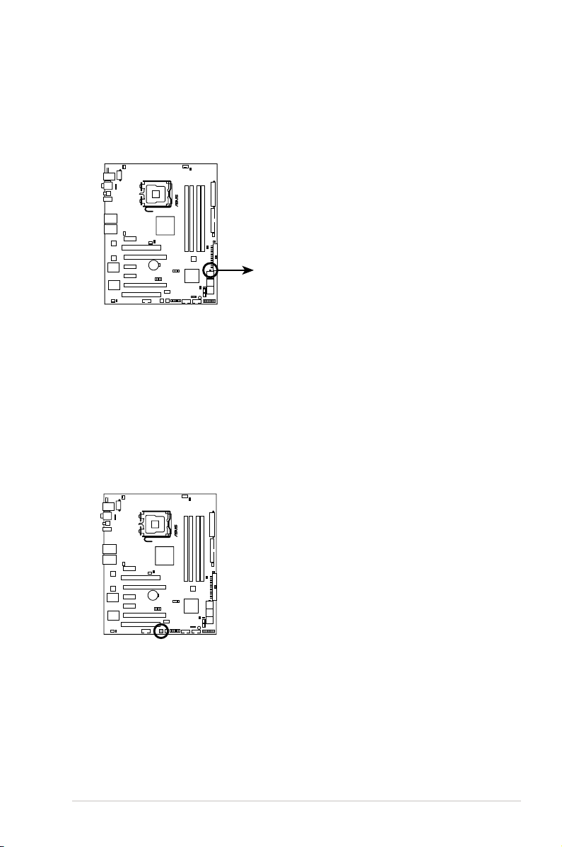
4. Hard Disk LED
MAXIMUS FORMULA
®
MAXIMUS FORMULA(Special Edition)/
MAXIMUS FORMULA Hard Disk LED
HD_LED
MAXIMUS FORMULA
®
MAXIMUS FORMULA(Special Edition)/
MAXIMUS FORMULA Power on switch
The hard disk LED is designed to indicate the hard disk activity. It blinks when
data is being written into or read from the hard disk drive. The LED does not
light up when there is no hard disk drive connected to the motherboard or
when the hard disk drive does not function.
5. Power LED
The motherboard comes with a power-on switch that lights up to indicate
that the system is ON, in sleep mode, or in soft-off mode. This is a reminder
that you should shut down the system and unplug the power cable before
removing or plugging in any motherboard component. The illustration below
shows the location of the onboard power-on switch.
ROG Maximus Formula (Special Edition) / Maximus Formula 2-3
MAXIMUS FORMULA
®
2.2 Motherboard overview
Before you install the motherboard, study the conguration of your chassis to
ensure that the motherboard ts into it.
Make sure to unplug the power cord before installing or removing the
motherboard. Failure to do so can cause you physical injury and damage
motherboard components.
2.2.1 Placement direction
When installing the motherboard, make sure that you place it into the chassis in the
correct orientation. The edge with external ports goes to the rear part of the chassis
as indicated in the image below.
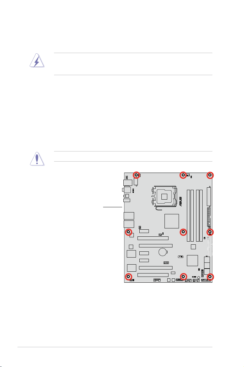
2.2.2 Screw holes
Place nine (9) screws into the holes indicated by circles to secure the motherboard
to the chassis.
DO NOT overtighten the screws! Doing so can damage the motherboard.
Place this side towards
the rear of the chassis
2-4 Chapter 2: Hardware information
 Loading...