

Page 1
®
Quick Start Guide
E1670
Page 2
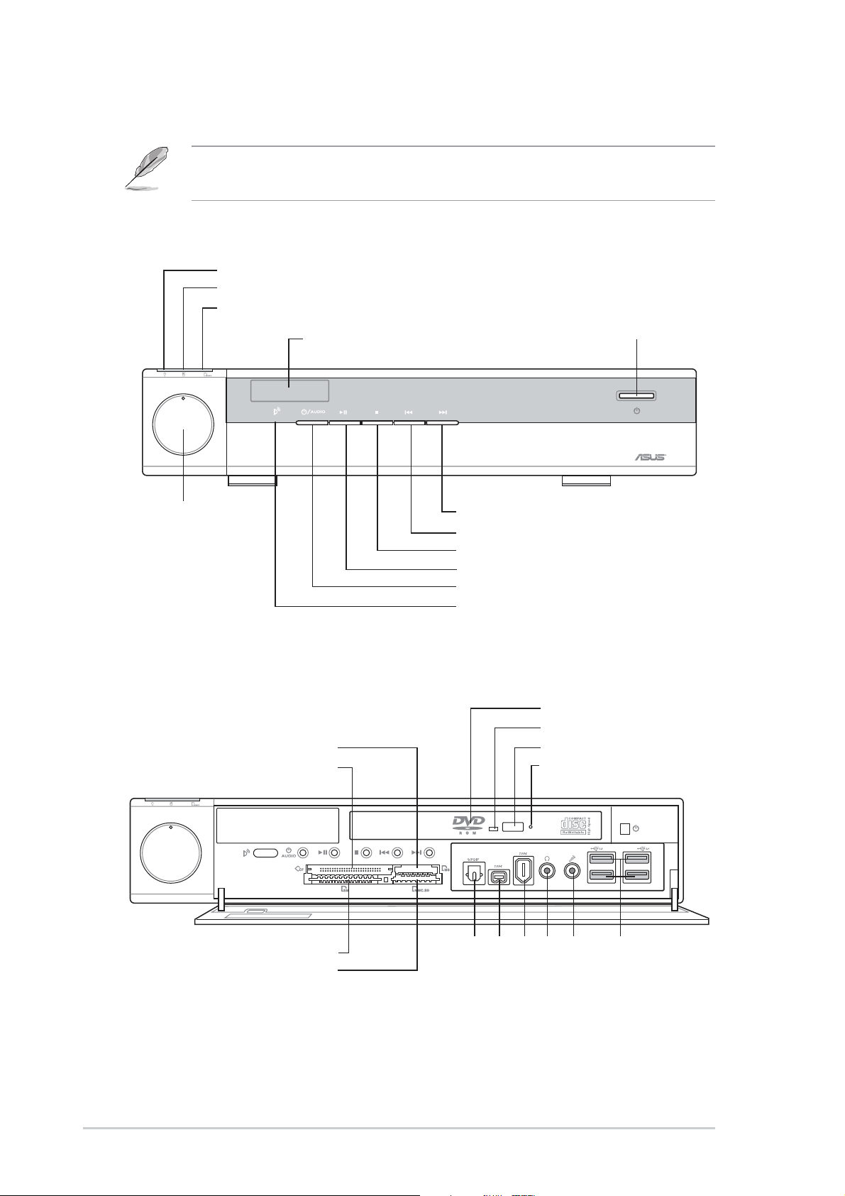
Front panel features
NOTE. The illustrations in this guide are for reference only. For detailed
information on your system’s specifications, refer to the user guide.
External
Power LED
HDD LED
Card reader LED
LED panel
— VOLUME +
System power button
System volume
dial
Internal
®
/MS Pro™ card slot
MS
CF®/Microdrive™ card slot
— VOLUME +
NEXT button
PREVIOUS button
STOP button
PLAY/PAUSE button
Audio DJ power button
Remote sensor
Slim optical drive
Drive activity LED
STOP/EJECT button
Emergency eject pinhole
SM® card slot
SD™/MMC card slot
Optical S/PDIF port
6-pin IEEE 1394 port
4-pin IEEE 1394 port
2
USB ports
Mic port
Headphone port
Quick Start Guide
Page 3
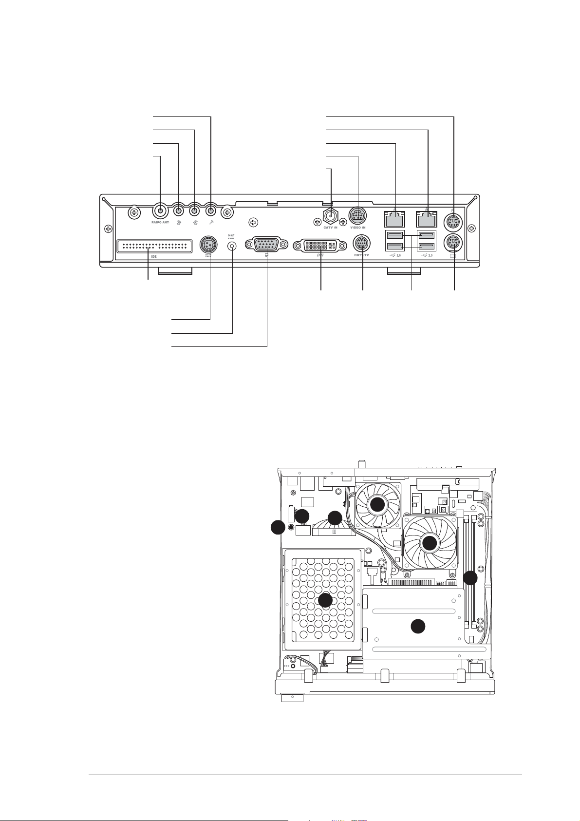
Rear panel features
Mic port
Line Out port
Line In port
Antenna port
Secondary IDE
connector
DC In socket
DC Out socket
VGA port
PS/2 mouse port
Gigabit LAN port
Ethernet LAN port
Video In port
Cable TV connector
DVI port
USB ports
HDTV/TV port
PS/2 keyboard port
Internal components
1. Standby power LED
2. HDD power plug
(to HDD power connector)
3. IDE cable (to HDD
connector)
4. Chassis fan
5. CPU fan
6. DIMM sockets
7. HDD metal tray
8. Optical drive shield
4
2
1
3
5
6
7
8
ASUS DiGiMatrix (AB-V10)
3
Page 4

Removing the top cover
2
1
Installing a hard disk drive
3
2
1
3
4
Insert the tray metal tacks into the
drive screw holes (two on the side
and two at the bottom)
7
5
Disengage the side
hooks from the HDD
tray and optical drive
shield
6
Align the side hooks with
the tray rail and optical
drive shield. Slide the
metal cover toward the
front panel until it fits in
place
Hand slot
Slide the metal
cover toward
the rear panel
4
Quick Start Guide
Page 5
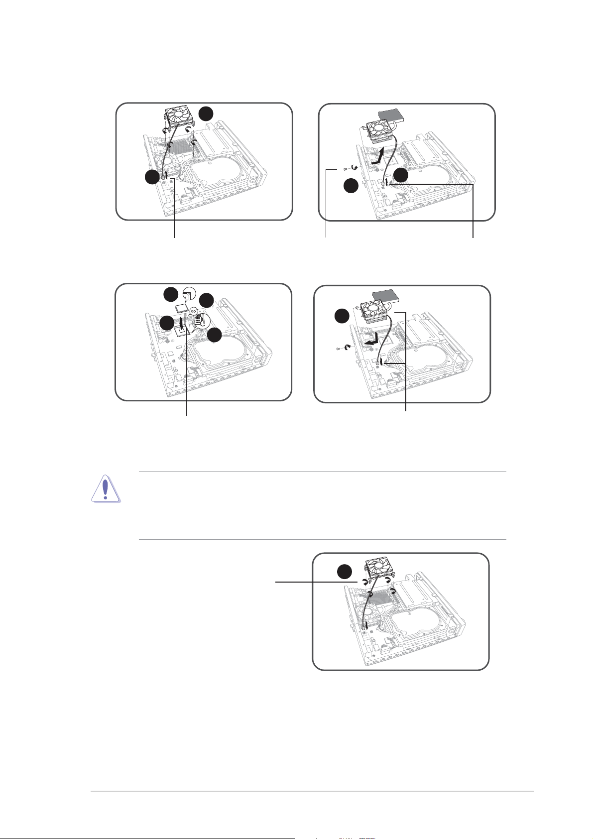
Installing a CPU
1
2
Disconnect the CPU fan cable
6
7
Unlock the socket by pressing the
lever sideways then lifting it up to a
90° angle
5
8
4
3
Remove the
bracket screw
9
Re-install the chassis fan and
heatsink assembly
Disconnect the
chassis fan cable
CAUTION! Make sure that the gold mark on the CPU matches the base
of the socket lever. The CPU fits only in one correct orientation. DO NOT
force the CPU into the socket to prevent bending the pins and damaging
the CPU
Re-install the CPU fan
10
ASUS DiGiMatrix (AB-V10)
5
Page 6

Installing a DIMM
1
1
2
Press the retaining
clips outward
Firmly insert the DIMM to
the socket until the
retaining clips snap back
in place and the DIMM is
properly seated.
CAUTION! A DDR DIMM is keyed with a notch so that it fits in only one
direction. DO NOT force a DIMM into a socket to avoid damaging the
DIMM.
Replacing the top cover
Align a DIMM on the socket such
that the notch on the DIMM
matches the break on the socket
3
3
Tabs
3
1
4
2
Fit the top cover tabs
with the chassis rail and
the front panel cover
tabs
6
4
Quick Start Guide
3
Page 7

Connecting cables
Power adapter and cable
3
DC in socket
DC in power plug
2
1
Power adapter
Power cable
Power outlet
Audio/Video cable
1
Audio/Video
cable plug
2
S-Video
port
Radio antenna
Audio out cable
Antenna
port
2
1
Audio I/O
ports
HDTV cable
HDTV cable plug
2
NOTE. You may also connect a regular TV set using the HDTV cable by
connecting the blue jack to the video input port of the TV set. The TV set
only receives video signals from the DiGiMatrix system.
Video out cable
1
HDTV
port
HDTV
RCA
input
ports
ASUS DiGiMatrix (AB-V10)
7
Page 8

Connecting external devices
To the front panel
— VOLUME +
To the rear panel
Audio Devices
Camera
HDD
Headphone
Mic
Scanner
Line OutLine In Mic
DiGiMatrix subsystem
Cable TV
VGA USB MouseDVI
RJ-45
PS/2 Mouse
PS/2 KB
8
Quick Start Guide
 Loading...