

ASUS CUBX-E, CUBX-L User Manual

®
CUBX-L/CUBX-E
Socket 370 ATX Motherboard
USER’S MANUAL
Special Features
CUBX-L
• UltraDMA/33 Support
• 2 USB Ports
CUBX-E
• UltraDMA/100 Support
• 5 USB Ports (2 standard, 3 upgradeable)

USER'S NOTICE
No part of this manual, including the products and software described in it, may be reproduced, transmitted, transcribed, stored in a retrieval system, or translated into any language in
any form or by any means, except documentation kept by the purchaser for backup purposes,
without the express written permission of ASUSTeK COMPUTER INC. (“ASUS”).
ASUS PROVIDES THIS MANUAL “AS IS” WITHOUT WARRANTY OF ANY KIND,
EITHER EXPRESS OR IMPLIED, INCLUDING BUT NOT LIMITED T O THE IMPLIED
WARRANTIES OR CONDITIONS OF MERCHANT ABILITY OR FITNESS FOR A PARTICULAR PURPOSE. IN NO EVENT SHALL ASUS, ITS DIRECTORS, OFFICERS,
EMPLOYEES OR AGENTS BE LIABLE FOR ANY INDIRECT, SPECIAL, INCIDENTAL, OR CONSEQUENTIAL DAMAGES (INCLUDING DAMAGES FOR LOSS OF
PROFITS, LOSS OF BUSINESS, LOSS OF USE OR DATA, INTERRUPTION OF BUSINESS AND THE LIKE), EVEN IF ASUS HAS BEEN ADVISED OF THE POSSIBILITY
OF SUCH DAMAGES ARISING FROM ANY DEFECT OR ERROR IN THIS MANUAL
OR PRODUCT.
Product warranty or service will not be extended if: (1) the product is repaired, modified or
altered, unless such repair, modification of alteration is authorized in writing by ASUS; or (2)
the serial number of the product is defaced or missing.
Products and corporate names appearing in this manual may or may not be registered trademarks or copyrights of their respective companies, and are used only for identification or
explanation and to the owners’ benefit, without intent to infringe.
• Adobe and Acrobat are registered trademarks of Adobe Systems Incorporated.
• Intel, LANDesk, and Pentium are registered trademarks of Intel Corporation.
• Trend and ChipAwayVirus are trademarks of Trend Micro, Inc.
• Windows and MS-DOS are registered trademarks of Microsoft Corporation.
The product name and revision number are both printed on the product itself. Manual revi-
sions are released for each product design represented by the digit before and after the period
of the manual revision number. Manual updates are represented by the third digit in the manual
revision number.
For previous or updated manuals, BIOS, drivers, or product release information, contact ASUS
at http://www.asus.com.tw or through any of the means indicated on the following page.
SPECIFICATIONS AND INFORMATION CONTAINED IN THIS MANUAL ARE FURNISHED FOR INFORMATIONAL USE ONLY, AND ARE SUBJECT TO CHANGE AT
ANY TIME WITHOUT NOTICE, AND SHOULD NOT BE CONSTRUED AS A COMMITMENT BY ASUS. ASUS ASSUMES NO RESPONSIBILITY OR LIABILITY FOR
ANY ERRORS OR INACCURACIES THAT MA Y APPEAR IN THIS MANUAL, INCLUDING THE PRODUCTS AND SOFTWARE DESCRIBED IN IT.
Copyright © 2000 ASUSTeK COMPUTER INC. All Rights Reserved.
Product Name: ASUS CUBX-L/CUBX-E
Manual Revision: 1.00 E606
Release Date: September 2000
2 ASUS CUBX-L/CUBX-E User’s Manual

ASUS CONTACT INFORMATION
ASUSTeK COMPUTER INC. (Asia-Pacific)
Marketing
Address: 150 Li-Te Road, Peitou, Taipei, Taiwan 112
Telephone: +886-2-2894-3447
Fax: +886-2-2894-3449
Email: info@asus.com.tw
Technical Support
MB/Others (Tel): +886-2-2890-7121 (English)
Notebook (Tel): +886-2-2890-7122 (English)
Desktop/Server (Tel): +886-2-2890-7123 (English)
Fax: +886-2-2895-9254
Email: tsd@asus.com.tw
WWW: www.asus.com.tw
FTP: ftp.asus.com.tw/pub/ASUS
ASUS COMPUTER INTERNATIONAL (America)
Marketing
Address: 6737 Mowry Avenue, Mowry Business Center, Building 2
Newark, CA 94560, USA
Fax: +1-510-608-4555
Email: tmd1@asus.com
Technical Support
Fax: +1-510-608-4555
Email: tsd@asus.com
WWW: www.asus.com
FTP: ftp.asus.com/Pub/ASUS
ASUS COMPUTER GmbH (Europe)
Marketing
Address: Harkortstr. 25, 40880 Ratingen, BRD, Germany
Fax: +49-2102-442066
Email: sales@asuscom.de (for marketing requests only)
Technical Support
Hotline: MB/Others: +49-2102-9599-0 Notebook: +49-2102-9599-10
Fax: +49-2102-9599-11
Support (Email): www.asuscom.de/de/support (for online support)
WWW: www.asuscom.de
FTP: ftp.asuscom.de/pub/ASUSCOM
ASUS CUBX-L/CUBX-E User’s Manual 3

CONTENTS
1. INTRODUCTION .............................................................................. 7
1.1 How This Manual Is Organized .................................................. 7
1.2 Item Checklist ............................................................................. 7
2. FEATURES ......................................................................................... 8
2.1 The ASUS CUBX-L/CUBX-E Motherboard ............................. 8
2.1.1 Specifications .................................................................. 8
2.1.2 Special Features............................................................. 10
2.1.3 Performance Features .................................................... 10
2.1.4 Intelligence .................................................................... 11
2.2 Motherboard Components ........................................................ 12
2.2.1 Component Locations.................................................... 13
3. HARDWARE SETUP ...................................................................... 14
3.1 CUBX-L/CUBX-E Motherboard Layout ................................. 14
3.2 Layout Contents ........................................................................ 15
3.3 Hardware Setup Procedure ....................................................... 17
3.4 Motherboard Settings................................................................ 17
3.5 System Memory (DIMM) ......................................................... 22
3.5.1 General DIMM Notes .................................................... 22
3.5.2 Memory Installation ...................................................... 23
3.6 Central Processing Unit (CPU) ................................................. 25
3.7 Expansion Cards ....................................................................... 26
3.7.1 Expansion Card Installation Procedure ......................... 26
3.7.2 Assigning IRQs for Expansion Cards............................ 27
3.7.3 Accelerated Graphics Port (AGP) ................................. 29
3.8 Connectors ................................................................................ 30
3.9 Starting Up the First Time ........................................................ 41
4. BIOS SETUP..................................................................................... 42
4.1 Managing and Updating Your BIOS ......................................... 42
4.1.1 Upon First Use of the Computer System....................... 42
4.1.2 Updating BIOS Procedures (only when necessary) ...... 43
4.2 BIOS Setup Program ................................................................ 45
4.2.1 BIOS Menu Bar ............................................................. 46
4.2.2 Legend Bar .................................................................... 46
4.3 Main Menu................................................................................ 48
4.3.1 Primary & Secondary Master/Slave .............................. 49
4.3.2 Keyboard Features ......................................................... 52
4 ASUS CUBX-L/CUBX-E User’s Manual

CONTENTS
4.4 Advanced Menu ........................................................................ 54
4.4.1 Chip Configuration ........................................................ 58
4.4.2 I/O Device Configuration .............................................. 60
4.4.3 PCI Configuration ......................................................... 62
4.4.4 Shadow Configuration................................................... 65
4.5 Power Menu .............................................................................. 66
4.5.1 Power Up Control.......................................................... 68
4.5.2 Hardware Monitor ......................................................... 70
4.6 Boot Menu ................................................................................ 71
4.7 Exit Menu ................................................................................. 73
5. SOFTWARE SETUP....................................................................... 75
5.1 Install Operating System........................................................... 75
5.2 Start Windows........................................................................... 75
5.3 Installing Drivers and Software ................................................ 75
6. SOFTWARE REFERENCE ........................................................... 79
6.1 ASUS PC Probe ........................................................................ 79
6.2 ASUS Update............................................................................ 84
7. APPENDIX........................................................................................ 85
7.1 PCI-L101 Fast Ethernet Card ................................................... 85
7.2 ASUS CIDB Intrusion Detection Module ................................ 87
7.3 Glossary .................................................................................... 89
INDEX ................................................................................................... 93
ASUS CUBX-L/CUBX-E User’s Manual 5

FCC & DOC COMPLIANCE
Federal Communications Commission Statement
This device complies with FCC Rules Part 15. Operation is subject to the following
two conditions:
• This device may not cause harmful interference, and
• This device must accept any interference received, including interference that
may cause undesired operation.
This equipment has been tested and found to comply with the limits for a Class B
digital device, pursuant to Part 15 of the FCC Rules. These limits are designed to
provide reasonable protection against harmful interference in a residential installation. This equipment generates, uses and can radiate radio frequency energy and, if
not installed and used in accordance with manufacturer's instructions, may cause
harmful interference to radio communications. However, there is no guarantee that
interference will not occur in a particular installation. If this equipment does cause
harmful interference to radio or television reception, which can be determined by
turning the equipment off and on, the user is encouraged to try to correct the interference by one or more of the following measures:
• Re-orient or relocate the receiving antenna.
• Increase the separation between the equipment and receiver.
• Connect the equipment to an outlet on a circuit different from that to which the
receiver is connected.
• Consult the dealer or an experienced radio/TV technician for help.
WARNING! Any changes or modifications to this product not expressly ap-
proved by the manufacturer could void any assurances of safety or performance
and could result in violation of Part 15 of the FCC Rules.
Reprinted from the Code of Federal Regulations #47, part 15.193, 1993. W ashington DC: Of fice of the
Federal Register, National Archives and Records Administration, U.S. Government Printing Office.
Canadian Department of Communications Statement
This digital apparatus does not exceed the Class B limits for radio noise emissions
from digital apparatus set out in the Radio Interference Regulations of the Canadian
Department of Communications.
This Class B digital apparatus complies with Canadian ICES-003.
Cet appareil numérique de la classe B est conforme à la norme NMB-003 du Canada.
6 ASUS CUBX-L/CUBX-E User’s Manual
1. INTRODUCTION
1.1 How This Manual Is Organized
This manual is divided into the following sections:
1. INTRODUCTION Manual information and checklist
2. FEATURES Production information and specifications
3. HARDWARE SETUP Intructions on setting up the motherboard.
4. BIOS SETUP Intructions on setting up the BIOS
5. SOFTWARE SETUP Intructions on setting up the included software
6. SOFTWARE REFERENCE Reference material for the included software
7. APPENDIX Optional items and general reference
1.2 Item Checklist
Please check that your package is complete. If you discover damaged or missing
items, please contact your retailer.
Manual / Checklist
1. INTRODUCTION
Package Contents
(1) ASUS Motherboard
(1) Ribbon cable for internal
UltraDMA/33 IDE drives
(1) Ribbon cable for one 5.25” and
two 3.5” floppy disk drives
(1) Bag of spare jumper caps
(1) ASUS Support CD with
drivers and utilities
(1) This Motherboard User’s
Manual
(1) 40-pin 80-conductor ibbon cable
for internal UltraDMA100/66/33
IDE drives (only for CUBX-E)
(1) Promise ATA100 Support Disk
(only for CUBX-E)
Optional Items
ASUS CIDB chassis intrusion detection module
ASUS IrDA-compliant infrared
module
ASUS PCI-L101 Wake-On-LAN
10/100 Ethernet Card
ASUS CUBX-L/CUBX-E User’s Manual 7

2. FEATURES
2.1 The ASUS CUBX-L/CUBX-E
Motherboard
The ASUS CUBX-L/CUBX-E is carefully designed for the demanding PC user who
wants advanced features processed by the fastest CPU.
2.1.1 Specifications
2. FEATURES
Specifications
• Latest Intel Processor Support
• Intel AGPset: Features Intel’s 440BX AGPset with I/O subsystems and front-side
• JumperFree™ Mode: Allows processor settings and easy overclocking of fre-
• Anti-Boot Virus BIOS: Features a programmable BIOS, offering enhanced
• PC100 Memory Support: Equipped with four DIMM sockets to support Intel
Intel Pentium® III 100MHz FSB Coppermine core FC-PGA
Intel Celeron™ 66MHz FSB Coppermine core FC-PGA
Intel Celeron™ 66MHz FSB Mendocino PPGA
bus (FSB) platform, which boosts the traditional 66MHz external bus speed to 100MHz.
quency and Vcore voltage all through BIOS setup when JumperFree™ mode is
enabled. Easy-to-use DIP switches instead of jumpers are included to allow
manual adjustment of the processor’s external frequency.
Advanced Configuration Power Interface (ACPI) support for W indows 98 com-
patibility , built-in firmware-based virus protection through T rend ChipA way V irus
codes, and autodetection of most devices for virtually automatic setup.
PC100-compliant SDRAMs (8, 16, 32, 64, 128, or 2 56MB) up to 1 GB. These
new SDRAMs are necessary to meet the critical enhanced 100MHz bus speed
requirement.
• Peripheral Wake Up: Supports modem, PS/2 keyboard, PS/2 mouse, and LAN
card wake up functions from sleep or soft-off mode.
• PC Health Monitoring: Provides an easier way to examine and manage system
status information, such as CPU and system voltages, temperatures, and fan
status through the onboard hardware ASIC and the bundled LDCM by Intel or
PC Probe from ASUS.
• AGP Slot: Supports an Accelerated Graphics Port card for high performance,
component level interconnect targeted at 3D graphical display applications using a 1X or 2X mode bus.
• PCI/ISA Expansion Slots: Provides five 32-bit PCI (rev 2.2) and two ISA ex-
pansion slots. PCI supports up to 133MB/s maximum throughput.
8
ASUS CUBX-L/CUBX-E User’s Manual

2. FEATURES
• Multi-I/O: Provides two high-speed UART compatible serial ports and one paral-
lel port with EPP and ECP capabilities.
• UltraDMA/33 Bus Master IDE: Comes with an onboard PCI Bus Master IDE
controller with two connectors that support four UltraDMA/33 IDE devices on
two channels. Supports UltraDMA/33, PIO Modes 3 and 4, and Bus Master IDE
DMA Mode 2, as well as Enhanced IDE devices, such as Tape Backup, CDROM, CD-R/RW, and LS-120 drives.
• Wake-On-LAN Connector: Supports Wake-On-LAN activity through an op-
tional ASUS PCI-L101 10/100 Fast Ethernet PCI card (see 7.1 PCI-L101 LAN
Card) or a similar ethernet card.
• Suspend and Go: Suspend-to-RAM (STR) provides maximum power savings
as an alternative to leaving the computer ON and QuickStart™ so that you do
not have to wait for a long time for system bootup (see Suspend-to-RAM Ca-
pability in 4.5 Power Menu for more information).
• Promise PCI-ATA100 Support (only on CUBX-E): Provides support to PCI-
ATA100 controller to provide Ultra DMA/100 solutions.
• Supports Up to 5 USB Ports (only on CUBX-E): Provides support for up to
five USB ports right out of the box.
Specifications
2. FEATURES
ASUS CUBX-L/CUBX-E User’s Manual 9

2. FEATURES
2.1.2 Special Features
• ACPI Ready: Advanced Configuration Power Interface (ACPI) provides more
Energy Saving Features for operating systems that support OS Direct Power
Management (OSPM) functionality . W ith these features implemented in the OS,
PCs can be ready around the clock, yet satisfy all the energy saving standards.
To fully utilize the benefits of ACPI, an ACPI-supported OS such as Windows
98 must be used.
2. FEATURES
Specifications
• Easy Installation: Incorporates BIOS that supports autodetection of hard disk
• New Compliancy: Both the BIOS and hardware levels of this motherboard meet
• Symbios SCSI BIOS: Supports optional ASUS SCSI controller cards through
2.1.3 Performance Features
• Concurrent PCI: Concurrent PCI allows multiple PCI transfers from PCI mas-
drives, PS/2 mouse, and Plug and Play devices to make the setup of hard disk
drives, expansion cards, and other devices virtually automatic.
the stringent requirements for PC’99 certification. The new PC’99 requirements
for systems and components are based on the following high-level goals: Support for Plug and Play compatibility and power management for configuring
and managing all system components, and 32-bit device drivers and installation
procedures for W indows95/98/NT. Color-coded connectors and descriptive icons
make identification easy as required by PC’99.
the onboard SYMBIOS firmware.
ter busses to the memory and processor.
• SDRAM Optimized Performance: Supports the new generation memory - Syn-
chronous Dynamic Random Access Memory (SDRAM) which increases the data
transfer rate to 800MB/s max using PC100-compliant SDRAM.
• High-Speed Data Transfer Interface: The CUBX-L motherboard supports
UltraDMA/33 and can handle data transfer rates up to 33MB/s. The CUBX-E
motherboard supports UltraDMA/100, which increases the data transfer rate to
100MB/s. UltraDMA/100 is backward compatible with DMA/66, DMA/33, and
DMA and with existing DMA devices and systems so there is no need to upgrade current EIDE/IDE drives and host systems. (UltraDMA/66 and UltraDMA/
100 require a 40-pin 80-conductor cable to be enabled.)
10
ASUS CUBX-L/CUBX-E User’s Manual

2. FEATURES
2.1.4 Intelligence
• Dual Function Power Button: Pushing the power button for less than 4 sec-
onds when the system is in the working state places the system into one of two
states: sleep mode or soft-off mode, depending on the BIOS or OS setting (see
PWR Button < 4 Secs in 4.5 Power Menu). When the power button is pressed
for more than 4 seconds, the system enters the soft-off mode regardless of the
BIOS setting.
• Fan Status Monitoring and Alarm: To prevent system overheat and system
damage, the CPU, power supply, and system fans can be monitored for RPM
and failure. All fans are set for its normal RPM range and alarm thresholds.
• Message LED (requires ACPI OS support): Turbo LEDs now act as informa-
tion providers. Through the way a particular LED illuminates, the user can determine if a message has been received from a fax/modem. A simple glimpse
provides useful information to the user.
• Remote Ring On (requires modem): This allows a computer with this mother-
board to be turned on remotely through an internal or external modem. With this
feature, users can access their computers from anywhere in the world!
Specifications
2. FEATURES
• System Resources Alert: Today’s operating systems such as Windows 95/98/
NT and OS/2, require much more memory and hard drive space to present enormous user interfaces and run large applications. The system resource monitor
will warn the user before the system resources are used up to prevent possible
application crashes. Suggestions will give the user information on managing
their limited resources more efficiently.
• Voltage Monitoring and Alert: System voltage levels are monitored to ensure
stable voltage to critical motherboard components. Voltage specifications are
more critical for future processors, so monitoring is necessary to ensure proper
system configuration and management.
ASUS CUBX-L/CUBX-E User’s Manual 11

2. FEATURES
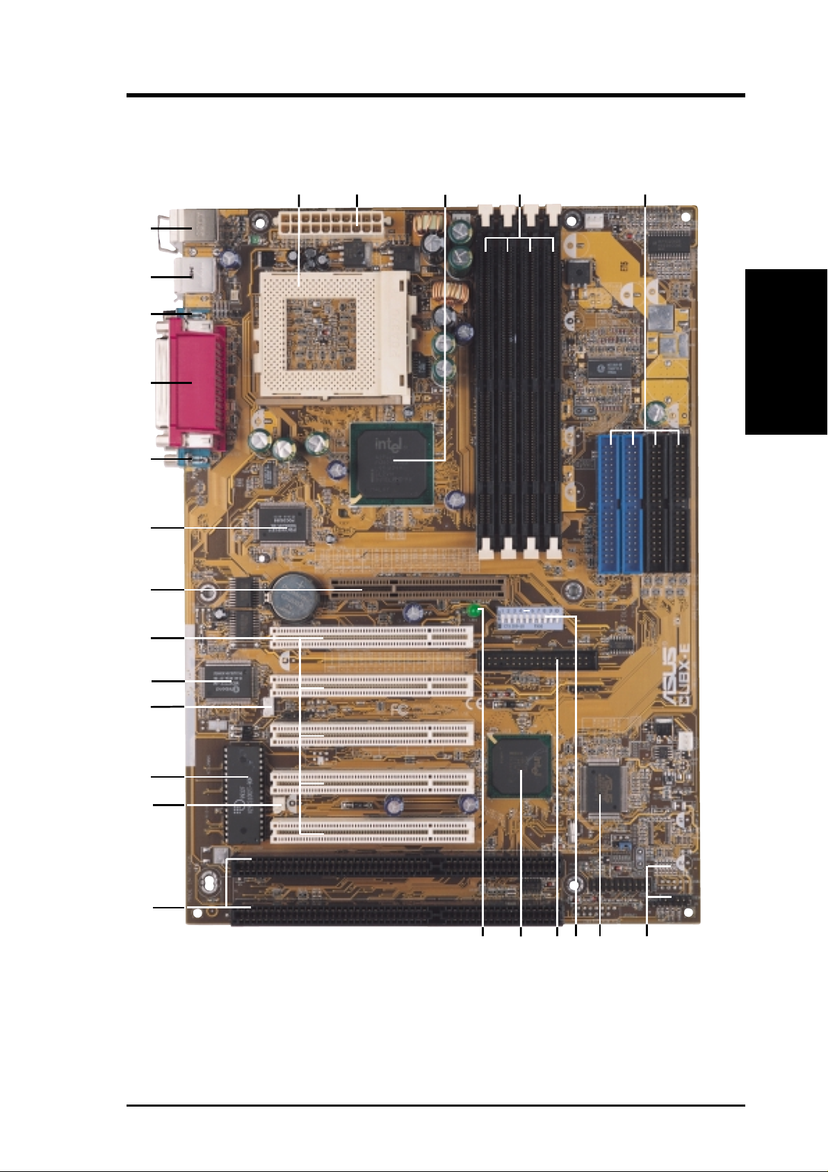
2.2 Motherboard Components
See opposite page for locations.
Location
Processor Support Socket 370 for Pentium III/Celeron Processors ....................... 1
Feature Setting DIP Switches ................................................... 8
100/66MHz system bus (Frequency Multiples 2.0-8.0)
MB Components
2. FEATURES
Chipsets Intel 440BX AGPset ................................................................. 3
Multi-I/O Chipset ................................................................... 16
Main Memory Maximum 1GB Supported
4 DIMM Sockets ...................................................................... 4
PC100/66 SDRAM Supported
Expansion Slots 5 PCI Slots .............................................................................. 17
2 ISA Slots .............................................................................. 12
1 Accelerated Graphics Port ................................................... 18
System I/O 2 UltraDMA/33 IDE Connectors ............................................. 5
2 UltraDMA/100 IDE Connectors (only on CUBX-E)............ 5
1 Floppy Disk Drive Connector ............................................... 9
Intel PIIX4E PCIset ................................................................ 10
1 Parallel Port Connector ....................................................... 21
2 Serial Port Connectors ................................................... 20, 22
2 USB Headers (only on CUBX-E) ......................................... 6
2 USB Connectors .................................................................. 23
1 PS/2 Mouse Connector .............................................. (Top) 24
1 PS/2 Keyboard Connector ................................... (Bottom) 24
BIOS AWARD BIOS, Programmable Flash 4Mbit EEPROM ........ 14
Supports Plug & Play, DMI, and Write Protection
Network Features Wake-On-LAN Connector...................................................... 15
Wake-On-Ring Connector ...................................................... 13
Hardware Monitoring System Voltage Monitoring (integrated in ASUS ASIC) ......... 7
3 Fan Power and Speed Monitoring Connectors
Power ATX Power Supply Connector ................................................. 2
Special Features Onboard Power LED .............................................................. 11
®
Promise
Form Factor ATX
UltraDMA/100 Controller (only on CUBX-E) ...... 19
12
ASUS CUBX-L/CUBX-E User’s Manual
2. FEATURES
2.2.1 Component Locations
1
4
3
2
1
0
9
234 5
2. FEATURES
Component Locations
8
7
6
5
4
3
12
11
10 79
8
6
ASUS CUBX-L/CUBX-E User’s Manual 13
3. HARDWARE SETUP
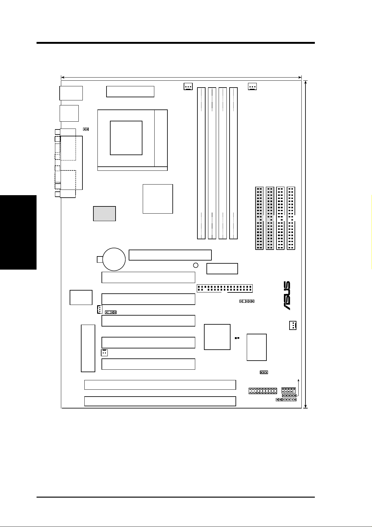
3.1 CUBX-L/CUBX-E Motherboard Layout
21.8 cm (8.6 in)
PS/2KBMS
T: Mouse
B: Keyboard
USB
T: Port1
B: Port
2
COM1
Motherboard Layout
COM2
3. H/W SETUP
JTPWR
PARALLEL PORT
ATXPWR
Socket 370
Promise
ATA100
CR2032 3V
Lithium Cell
CMOS Power
CPU_FAN
Intel
440BX
AGPset
Accelerated Graphics Port
LED1
PCI1
DIMM1 (64/72 bit, 168-pin module)
0
1
Row
PWR_FAN
SECONDARY IDE
THIRD IDE
FOURTH IDE
DIMM2 (64/72 bit, 168-pin module)
DIMM3 (64/72 bit, 168-pin module)
DIMM4 (64/72 bit, 168-pin module)
2
4
6
3
5
7
DSW
DIP
Switches
FLOPPY
®
PRIMARY IDE
30.5 cm (12.0 in)
Multi-I/O
WOL_CON
2Mb Flash EEPROM
CHASIS
WOR
(Programable BIOS)
PCI2
PCI3
PCI4
PCI5
ISA1
ISA2
Intel
PIIX4E
PCIset
SMB
CLRTC
ASUS
ASIC
with
Hardware
Monitor
PANEL
IDELED
CHA_FAN
JEN
USB3A
USB2
IR
(Grayed components are only available on the CUBX-E motherboard.)
14
ASUS CUBX-L/CUBX-E User’s Manual

3. HARDWARE SETUP
3.2 Layout Contents
Motherboard Settings
1) JEN p. 18 JumperFree Mode Setting (Disable/Enable)
2) DSW 6 p. 20 AGP Bus Frequency Setting
3) DSW 5–10 p. 20 CPU External Frequency Selection
4) DSW 1-4 p. 21 CPU Core:BUS Frequency Multiple Selection
Expansion Slots/Sockets
1) System Memory p.22 System Memory Support
2) DIMM1/2/3/4 p.22 DIMM Memory Module Support
3) Socket 370 p.25 CPU Support
4) PCI1/2/3/4/5 p.27 32-bit PCI Bus Expansion Slots
5) ISA1/ISA2 p.27 16-bit ISA Bus Expansion Slots
6) AGP p.29 Accelerated Graphics Port
Connectors
1) PS2KBMS p.30 PS/2 Mouse Port Connector (6 pin-female)
2) PS2KBMS p.30 PS/2 Keyboard Port Connector (6-pin female)
3) USB p.31 Universal Serial Bus Connectors 1 & 2 (Two 4-pin female)
4) PRINTER p.31 Parallel Port Connector (25-pin female)
5) COM1/COM2 p.31 Serial Port Connector (Two 9-pin male)
6) CHASSIS p.32 Chassis Intrusion Lead (4-1 pins)
7) PRIMARY IDE p.33 UltraDMA/66 IDE Connectors (Two 40-1 pins)
SECONDARY IDE
THIRD IDE UltraDMA/100 IDE Connectors (only on CUBX-E)
FOURTH IDE
8) FLOPPY p. 33 Floppy Disk Drive Port Connector (34 pins)
9) WOL_CON p. 34 Wake-On-LAN Connector (3 pins)
10) WOR p. 34 Wake-On-Ring Connector (2 pins)
11) IDELED p. 35 IDE Activity LED (2 pins)
12) PWR_, CPU_,CHA_FAN p. 35 Chassis, Power Supply, CPU Fan Connectors (3 pins)
13) IR p. 36 Infrared Module Connector (5 pins)
3. H/W SETUP
Layout Contents
14) SMB p. 37 SMBus Connector (5-1 pins)
15) USB2, USB3A p. 37 USB Headers (10-1 pins, 5-1 pins)
16)
PWR.LED (
17)
KEYLOCK (
18) SPEAKER (PANEL) p. 38 System Warning Speaker Connector (4 pins)
PANEL
PANEL
)
p. 38 System Power LED Lead (3 pins)
)
p. 38 Keyboard Lock Switch Lead (2 pins)
ASUS CUBX-L/CUBX-E User’s Manual 15

19) MSG.LED (PANEL) p. 38 System Message LED (2 pins)
20) SMI (PANEL) p. 38 System Management Interrupt Lead (2 pins)
21) PWR.SW (PANEL) p. 38 ATX / Soft-Off Switch Lead (2 pins)
22) RESET (PANEL) p. 38 Reset Switch Lead (2 pins)
23) ATXPWR p. 39 ATX Power Supply Connector (20 pins)
24) JTPWR p. 39 Power Supply Thermal Sensor Connector (2 pins)
Layout Contents
3. H/W SETUP
3. HARDWARE SETUP
16
ASUS CUBX-L/CUBX-E User’s Manual

3. HARDWARE SETUP
3.3 Hardware Setup Procedure
Before using your computer, you must complete the following steps:
1. Check Motherboard Settings
2. Install Memory Modules
3. Install the Central Processing Unit (CPU)
4. Install Expansion Cards
5. Connect Ribbon Cables, Panel Wires, and Power Supply
6. Setup the BIOS Software
3.4 Motherboard Settings
This section explains in detail how to change your motherboard’s function settings
through the use of switches and/or jumpers.
WARNING! Computer motherboards and expansion cards contain very delicate
Integrated Circuit (IC) chips. To protect them against damage from static electricity, you should follow some precautions whenever you work on your computer.
1. Unplug your computer when working on the inside.
2. Use a grounded wrist strap before handling computer components. If you
do not have one, touch both of your hands to a safely grounded object or to
a metal object, such as the power supply case.
3. Hold components by the edges and try not to touch the IC chips, leads or
connectors, or other components.
4. Place components on a grounded antistatic pad or on the bag that came with
the component whenever the components are separated from the system.
WARNING! Make sure that you unplug your power supply when adding or
removing system components. Failure to do so may cause severe damage to
your motherboard, peripherals, and/or components. The onboard LED when lit
acts as a reminder that the system is in suspend or soft-off mode and not powered
OFF.
3. H/W SETUP
Motherboard Settings
®
ON
Standby
Power
CUBX-L/CUBX-E Onboard LED
OFF
Powered
Off
ASUS CUBX-L/CUBX-E User’s Manual 17

3. HARDWARE SETUP
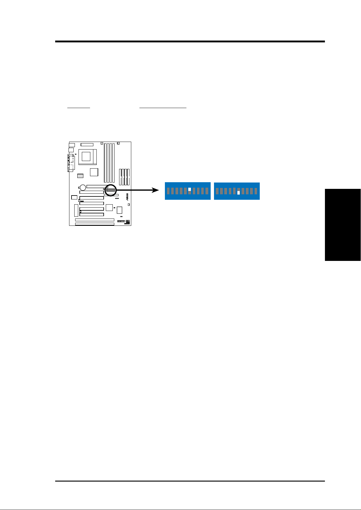
Motherboard Features Settings (DIP Switches - DSW)
The motherboard’s onboard functions are adjusted through the DIP switches. The
white block represents the switch’s position. The example below shows all the
switches in the OFF position.
1. Frequency Multiple
2. Frequency Multiple
3. Frequency Multiple
4. Frequency Multiple
5. (Reserved)
6. AGP Frequency Selection
7. Frequency Selection
®
8. Frequency Selection
9. Frequency Selection
10. Frequency Selection
Motherboard Settings
CUBX-L/CUBX-E DIP Switches
3. H/W SETUP
1) JumperFree™ Mode (JEN)
This jumper allows you to enable or disable the JumperFree™ mode. The
JumperFree™ mode allows processor settings to be made through the BIOS
setup (see 4.4 Advanced Menu).
Setting JEN
Enable (JumperFree) [2-3] (default)
Disable (Jumper) [1-2]
DSW
ON
12345678910
DSW
ON
12345678910
ON
OFF
OFF
18
®
JEN
12
Jumper JumperFree
2
3
CUBX-L/CUBX-E Jumper Mode Setting
NOTE: In JumperFree™ mode, all dip switches (DSW) must be set to OFF.
ASUS CUBX-L/CUBX-E User’s Manual
3. HARDWARE SETUP
2) AGP Bus Frequency Setting (DSW Switch 6)
This option sets the frequency ratio between the AGP bus frequency and the DRAM
(CPU bus) frequency. The default sets the AGP bus frequency to be 2/3 of the
DRAM frequency. When the CPU/DRAM frequency is set to 66MHz, set this
switch to [ON]. See the processor table on the next page.
Setting DSW Switch 6
DRAM Freq. x 2/3 [OFF] (default)
DRAM Freq. x 1 [ON]
ON
®
123456 78910
CUBX-L/CUBX-E AGP Bus Frequency Setting
ON
123456 78910
DRAM Freq. x2/3DRAM Freq. x1
3. H/W SETUP
Motherboard Settings
ASUS CUBX-L/CUBX-E User’s Manual 19
3. HARDWARE SETUP
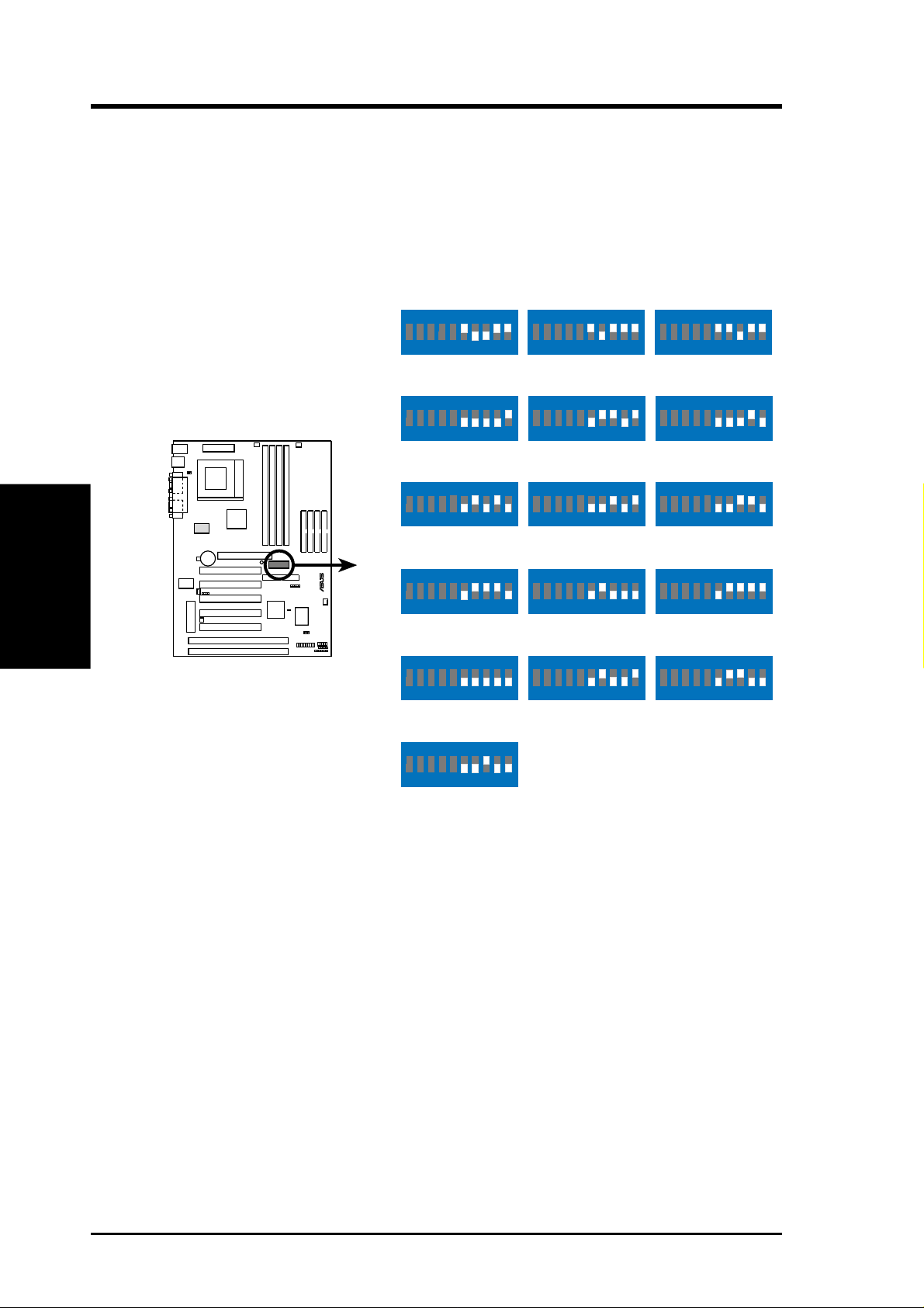
3) CPU External Frequency Selection (DSW Switches 7-10)
This option tells the clock generator what frequency to send to the CPU, DRAM, and
the PCI bus. This allows the selection of the CPU’s External frequency (or BUS Clock).
The BUS Clock multiplied by the Frequency Multiple equals the CPU’s Internal fre-
quency (the advertised CPU speed).
Motherboard Settings
3. H/W SETUP
CUBX-L/CUBX-E CPU
External Frequency
Selection
CPU/DRAM
PCI BUS
CPU/DRAM
PCI BUS
CPU/DRAM
PCI BUS
®
CPU/DRAM
PCI BUS
CPU/DRAM
PCI BUS
ON
12345678910
→
66.0MHz
→
33.4MHz
ON
12345678910
→
100.0MHz
→
33.4MHz
ON
12345678910
→
110.0MHz
→
36.7MHz
ON
12345678910
→
120.0MHz
→
40.0MHz
ON
12345678910
→
133.0MHz
→
33.3MHz
ON
ON
12345678910
75.0MHz
37.5MHz
ON
12345678910
103.0MHz
34.3MHz
ON
12345678910
112.0MHz
37.3MHz
ON
12345678910
124.0MHz
31.0MHz
ON
12345678910
133.0MHz
44.3MHz
ON
12345678910
83.0MHz
41.6MHz
ON
12345678910
105.0MHz
35.0MHz
ON
12345678910
115.0MHz
38.3MHz
ON
12345678910
124.0MHz
41.3MHz
ON
12345678910
140.0MHz
35.0MHz
12345678910
CPU/DRAM
PCI BUS
→
150.0MHz
→
37.5MHz
NOTE: Overclocking your processor is not recommended. It may result in a slower
speed.
20
ASUS CUBX-L/CUBX-E User’s Manual
3. HARDWARE SETUP
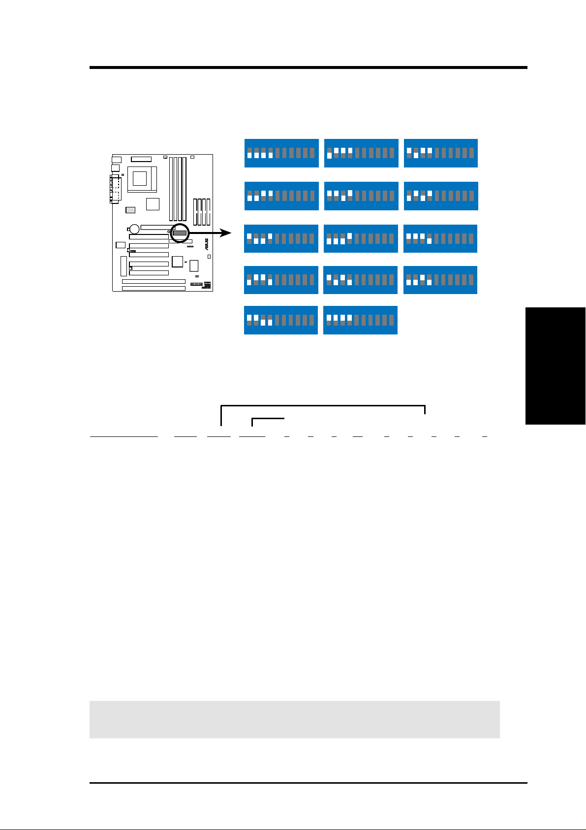
4) CPU Core:BUS Frequency Multiple (DSW Switches 1-4)
This option sets the frequency multiple between the Internal frequency of the
CPU and the CPU’s External frequency. These must be set in conjunction with the
CPU Bus Frequency.
DSW
ON
ON
ON
12345678910
2.5x(5/2)
ON
12345678910
ON
12345678910
5.5x(11/2)
ON
12345678910
7.0x(7/1)
ON
12345678910
3.0x(3/1)
ON
12345678910
4.5x(9/2)4.0x(4/1)
ON
12345678910
6.0x(6/1)
ON
12345678910
7.5x(15/2)
®
CUBX-L/CUBX-E CPU :
12345678910
2.0x(2/1)
ON
12345678910
3.5x(7/2)
ON
12345678910
5.0x(5/1)
ON
12345678910
6.5x(13/2)
ON
BUS Frequency Multiple
12345678910
8.0x(8/1)
12345678910
TEST
Manual CPU Settings
NOTE: JumperFree mode must be disabled .
Set the DIP switches by the Internal speed of your processor as follows:
(CPU BUS Freq.) (Freq. Multiple) (AGP)
Intel CPU Model
Pentium III 800MHz 8.0x 100MHz [OFF][OFF][OFF] [ON] [ON] [ON] [OFF][OFF] [OFF]
Pentium III 750MHz 7.5x 100MHz [OFF][OFF][OFF] [ON] [OFF][OFF][ON] [OFF] [OFF]
Pentium III 700MHz 7.0x 100MHz [OFF][OFF][OFF] [ON] [ON] [OFF] [ON][OFF]] [OFF]
Pentium III 650MHz 6.5x 100MHz [OFF][OFF][OFF] [ON] [OFF][ON] [ON] [OFF] [OFF]
Pentium III 600MHz 6.0x 100MHz [OFF][OFF][OFF] [ON] [ON] [ON] [ON] [OFF] [OFF]
Pentium III 550MHz 5.5x 100MHz [OFF][OFF][OFF] [ON] [OFF][OFF][OFF][ON] [OFF]
Pentium III 500MHz 5.0x 100MHz [OFF][OFF][OFF] [ON] [ON] [OFF][OFF] [ON] [OFF]
Pentium III 450MHz 4.5x 100MHz [OFF][OFF][OFF] [ON] [OFF][ON] [OFF] [ON] [OFF]
Freq. Mult. Bus F. 7 8 9 10 1 2 3 4 6
3. H/W SETUP
Motherboard Settings
Celeron 533MHz 8.0x 66MHz [OFF][OFF] [ON] [ON] [ON] [ON] [OFF][OFF] [ON]
Celeron 500MHz 7.5x 66MHz [OFF][OFF] [ON] [ON] [OFF][OFF] [ON] [OFF] [ON]
Celeron 466MHz 7.0x 66MHz [OFF][OFF] [ON] [ON] [ON][OFF] [ON] [OFF] [ON]
Celeron 433MHz 6.5x 66MHz [OFF][OFF] [ON] [ON] [OFF] [ON] [ON] [OFF] [ON]
Celeron 400MHz 6.0x 66MHz [OFF][OFF] [ON] [ON] [ON] [ON] [ON] [OFF] [ON]
Celeron 366MHz 5.5x 66MHz [OFF][OFF] [ON] [ON] [OFF][OFF][OFF][ON] [ON]
Celeron 333MHz 5.0x 66MHz [OFF][OFF] [ON] [ON] [ON][OFF][OFF] [ON] [ON]
Celeron 300MHz 4.5x 66MHz [OFF][OFF] [ON] [ON] [OFF] [ON] [OFF] [ON] [ON]
Celeron 266MHz 4.0x 66MHz [OFF][OFF] [ON] [ON] [ON] [ON] [OFF] [ON] [ON]
For updated processor settings, please visit ASUS’ web site (see ASUS CONTACT INFORMATION).
WARNING! Frequencies other than the recommended CPU bus frequencies
are not guaranteed to be stable.
ASUS CUBX-L/CUBX-E User’s Manual 21
3. HARDWARE SETUP
3.5 System Memory (DIMM)
NOTE: No hardware or BIOS setup is required after adding or removing memory.
This motherboard uses only Dual Inline Memory Modules (DIMMs). S ockets are
available for 3.3Volt (power level) unbuffered Synchronous Dynamic Random Ac-
cess Memory (SDRAM). One side (with memory chips) of the DIMM takes up one
row on the motherboard.
To utilize the chipset’s Error Checking and Correction (ECC) feature, you must use a
DIMM module with 9 chips per side (standard 8 chips/side + 1 ECC chip).
Memory speed setup is recommended through SDRAM Configuration in 4.4.1
Chip Configuration.
System Memory
3. H/W SETUP
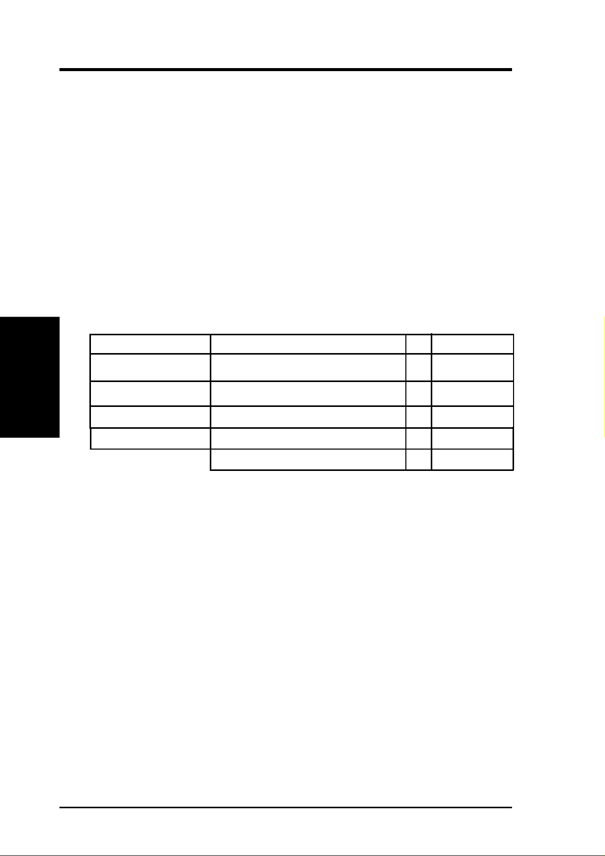
Install memory in any combination as follows:
DIMM Location 168-pin DIMM Total Memory
Socket 1 (Rows 0&1) SDRAM 8, 16, 32, 64, 128, 256MB x1
Socket 2 (Rows 2&3) SDRAM 8, 16, 32, 64, 128, 256MB x1
Socket 3 (Rows 4&5) SDRAM 8, 16, 32, 64, 128, 256MB x1
Socket 4 (Rows 6&7) SDRAM 8, 16, 32, 64, 128, 256MB x1
3.5.1 General DIMM Notes
• For the system CPU bus to operate at 100MHz, use only PC100-compliant
• ASUS motherboards support SPD (Serial Presence Detect) DIMMs. This is the
• Two possible memory chips are supported: SDRAM with and without ECC.
• SDRAM chips are generally thinner with higher pin density than EDO (Ex-
• BIOS shows SDRAM memory on bootup screen.
• Single-sided DIMMs come in 16, 32, 64,128MB; double-sided come in 32, 64,
Total System Memory (Max 1024MB) =
DIMMs. When this motherboard operates at 100MHz, most system will not
even boot if non-compliant modules are used because of the strict timing issues
involved under this speed. If your DIMMs are not PC100-compliant, set the
CPU bus frequency to 66MHz RAM to ensure system stability.
memory of choice for best performance vs. stability.
tended Data Output) chips.
128, 256MB.
22
ASUS CUBX-L/CUBX-E User’s Manual
3. HARDWARE SETUP
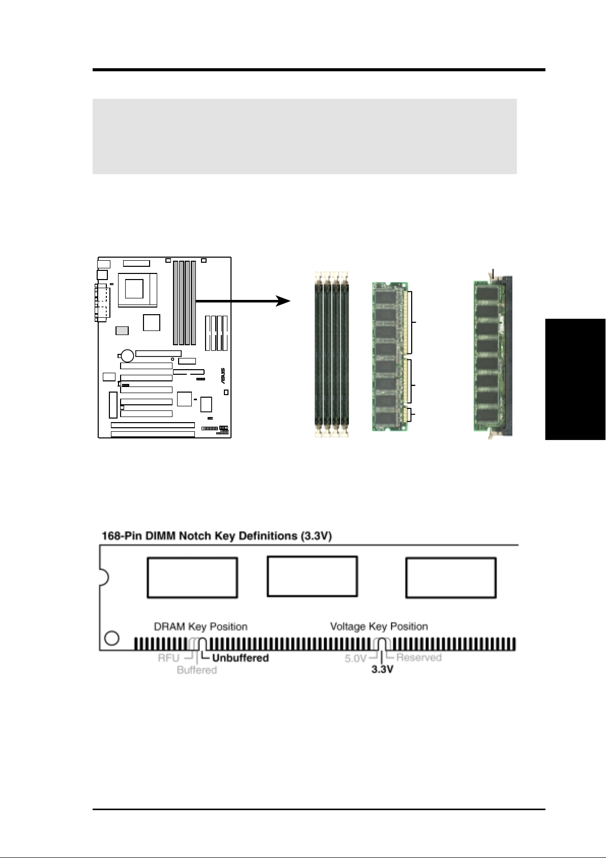
3.5.2 Memory Installation
WARNING! Make sure that you unplug your power supply when adding or
removing memory modules or other system components. Failure to do so may
cause severe damage to both your motherboard and expansion cards (see 3.3
Hardware Setup Procedure for more information).
Insert the module(s) as shown. Because the number of pins are different on either
side of the breaks, the module will only fit in the orientation shown. DRAM SIMM
modules have the same pin contacts on both sides. SDRAM DIMMs have different
pin contacts on each side and therefore have a higher pin density.
Lock
88 Pins
®
60 Pins
20 Pins
CUBX-L/CUBX-E 168-Pin DIMM Memory Sockets
The DIMMs must be 3.3Volt unbuffered SDRAMs. To determine the DIMM type,
check the notches on the DIMMs (see figure below).
3. H/W SETUP
System Memory
The notches on the DIMM will shift between left, center, or right to identify the type
and also to prevent the wrong type from being inserted into the DIMM slot on the
motherboard. You must tell your retailer the correct DIMM type before purchasing.
This motherboard supports four clock signals per DIMM.
ASUS CUBX-L/CUBX-E User’s Manual 23

(This page was intentionally left blank.)
System Memory
3. H/W SETUP
3. HARDWARE SETUP
24
ASUS CUBX-L/CUBX-E User’s Manual
3. HARDWARE SETUP
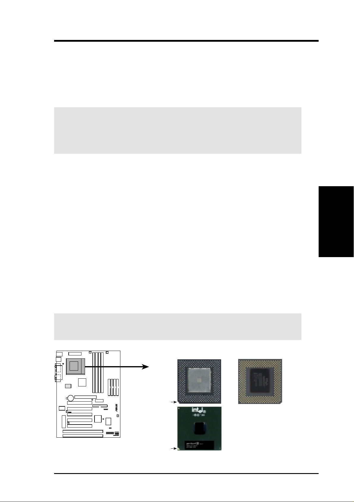
3.6 Central Processing Unit (CPU)
The motherboard provides a ZIF Socket 370. The CPU that came with the motherboard should have a fan attached to it to prevent overheating. If this is not the case,
then purchase a fan before you turn on your system.
WARNING! Be sure that there is sufficient air circulation across the processor’s
heatsink by regularly checking that your CPU fan is working. W ithout sufficient
circulation, the processor could overheat and damage both the processor and the
motherboard. You may install an auxiliary fan, if necessary.
To install a CPU, first turn off your system and remove its cover. Locate the ZIF
socket and open it by first pulling the lever sideways away from the socket then
upwards to a 90-degree angle. Insert the CPU with the correct orientation as shown.
The notched corner should point towards the end of the lever . Because the CPU has
a corner pin for two of the four corners, the CPU will only fit in the orientation as
shown. The picture is for reference only; you should have a CPU fan that covers the
face of the CPU. With the added weight of the CPU fan, no force is required to
insert the CPU. Once completely inserted, close the socket’s lever while holding
down the CPU. After the CPU is , install an Intel recommended fan heatsink. Locate
the CPU fan connector (see 3.1 Motherboard Layout or 3.8 Connectors) and connect the CPU fan cable to it.
CPU
3. H/W SETUP
NOTE: Do not forget to set the correct Bus Frequency and Multiple (frequency
multiple setting is available only on unlocked processors) for your Socket 370 processor or else boot-up may not be possible. Socket 370 processors provide internal
thermal sensing so that a socket mounted thermal resistor is not needed.
CAUTION! Be careful not to scrape the motherboard when mounting a clamp-
style processor fan or else damage may occur to the motherboard.
Socket 370 CPU (Top) Socket 370 CPU (Bottom)
Celeron
Notch
Pentium III
CUBX-L/CUBX-E
Socket 370
®
Golden Arrow
ASUS CUBX-L/CUBX-E User’s Manual 25
3.7 Expansion Cards
WARNING! Unplug your power supply when adding or removing expansion
cards or other system components. Failure to do so may cause severe damage to
both your motherboard and expansion cards.
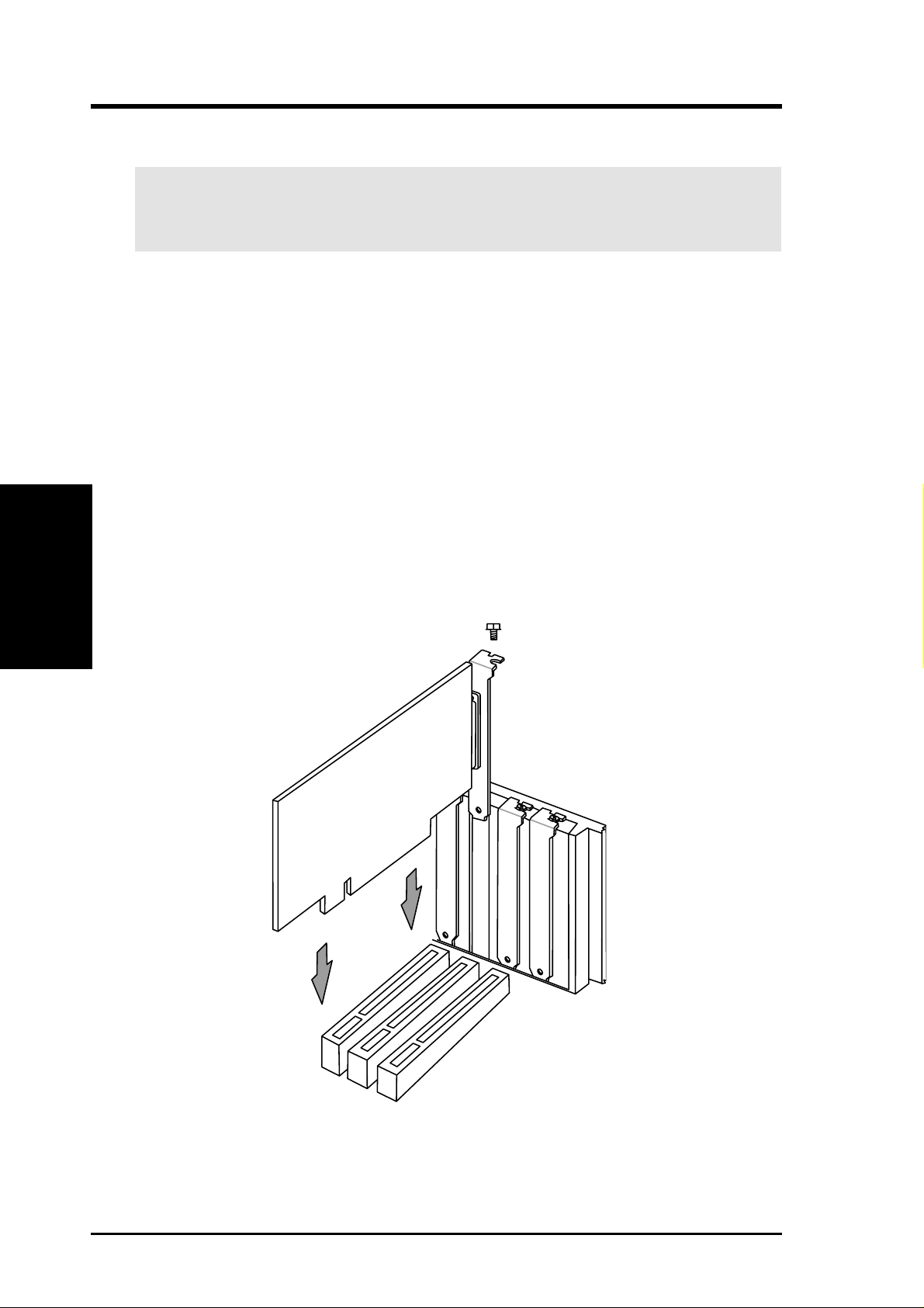
3.7.1 Expansion Card Installation Procedure
1. Read the documentation for your expansion card and make any necessary hardware or software settings for your expansion card, such as jumpers.
2. Remove your computer system’s cover and the bracket plate on the slot you
intend to use. Keep the bracket for possible future use.
3. Carefully align the card’s connectors and press firmly.
4. Secure the card on the slot with the screw you removed above.
Expansion Cards
3. H/W SETUP
5. Replace the computer system’s cover.
6. Set up the BIOS if necessary
(such as IRQ xx Used By ISA: Yes in 4.4.3 PCI Configuration)
7. Install the necessary software drivers for your expansion card.
3. HARDWARE SETUP
26 ASUS CUBX-L/CUBX-E User’s Manual

3. HARDWARE SETUP
3.7.2 Assigning IRQs for Expansion Cards
Some expansion cards need an IRQ to operate. Generally, an IRQ must be exclusively assigned to one use. In a standard design, there are 16 IRQs available but
most of them are already in use, leaving 6 IRQs free for expansion cards. If your
motherboard has PCI audio onboard, an additional IRQ will be used. If your motherboard also has MIDI enabled, another IRQ will be used, leaving 4 IRQs free.
IMPORTANT: If using PCI cards on shared slots, make sure that the drivers support “Share IRQ” or that the cards do not need IRQ assignments. Conflicts will arise
between the two PCI groups that will make the system unstable or cards inoperable.
The following table lists the default IRQ assignments for standard PC devices. Use
this table when configuring your system and for resolving IRQ conflicts.
Standard Interrupt Assignments
IRQ Priority Standard Function
0 1 System Timer
1 2 Keyboard Controller
2 N/A Programmable Interrupt
3* 11 Communications Port (COM2)
4* 12 Communications Port (COM1)
5* 13 Sound Card (sometimes LPT2)
6 14 Floppy Disk Controller
7* 15 Printer Port (LPT1)
8 3 System CMOS/Real Time Clock
9* 4 ACPI Mode when used
10* 5 IRQ Holder for PCI Steering
11* 6 IRQ Holder for PCI Steering
12* 7 PS/2 Compatible Mouse Port
13 8 Numeric Data Processor
14* 9 Primary IDE Channel
15* 10 Secondary IDE Channel
3. H/W SETUP
Expansion Cards
*These IRQs are usually available for ISA or PCI devices.
Interrupt Request Table for this Motherboard
INT-A INT-B INT-C INT-D
PCI slot 1 shared —— —
PCI slot 2 — shared ——
PCI slot 3 ——shared —
PCI slot 4 ———shared
PCI slot 5 ———shared
AGP slot shared ———
ATA100 controller — shared ——
Onboard USB controller ———shared
SMBus ————
ASUS CUBX-L/CUBX-E User’s Manual 27

Both ISA and PCI expansion cards may require IRQs. System IRQs are available to
cards installed in the ISA expansion bus first, then any remaining IRQs are available
to PCI cards. Currently, there are two types of ISA cards.
The original ISA expansion card design, now referred to as legacy ISA cards, requires that you configure the card’s jumpers manually and then install it in any
available slot on the ISA bus. To see a map of your used and free IRQs in W indows
98, the Control Panel icon in My Computer, contains a System icon, which gives
you a Device Manager tab. Double-clicking on a specific hardware device gives
you the Resources tab which shows the Interrupt number and address. Double-click
Computer to see all the interrupts and addresses for your system. Make sure that no
two devices use the same IRQ or your computer will experience problems when
those two devices are in use at the same time.
To simplify this process, this motherboard complies with the Plug and Play (PNP)
specification which was developed to allow automatic system configuration when-
3. H/W SETUP
DMA Channels
ever a PNP-compliant card is added to the system. For PNP cards, IRQs are assigned automatically from those available.
3. HARDWARE SETUP
If the system has both legacy and PNP ISA cards installed, IRQs are
assigned to PNP cards from those not used by legacy cards. The PCI and PNP configuration of the BIOS setup utility can be used to indicate which IRQs are being
used by legacy cards. For older legacy cards that do not work with the BIOS, you
can contact your vendor for an ISA Configuration Utility.
An IRQ number is automatically assigned to PCI expansion cards after those used
by legacy and PNP ISA cards. In the PCI bus design, the BIOS automatically assigns an IRQ to PCI cards that require an IRQ. To install a PCI card, you need to set
the INT (interrupt) assignment. Since all the PCI slots on this motherboard use an
INTA #, be sure that the jumpers on your PCI cards are set to INT A.
Assigning DMA Channels for ISA Cards
Some ISA cards, both legacy and PNP , may also need to use a DMA (Direct Memory
Access) channel. DMA assignments for this motherboard are handled the same way
as the IRQ assignment process described earlier. You can select a DMA channel in
the PCI and PNP configuration section of the BIOS Setup utility.
IMPORTANT: To avoid conflicts, reserve the necessary IRQs and DMAs for
legacy ISA cards (see 4.4.3 PCI Configuration. Choose Yes in IRQ xx Used By
ISA and DMA x Used By ISA for those IRQs and DMAs you want to reserve).
28 ASUS CUBX-L/CUBX-E User’s Manual
3. HARDWARE SETUP
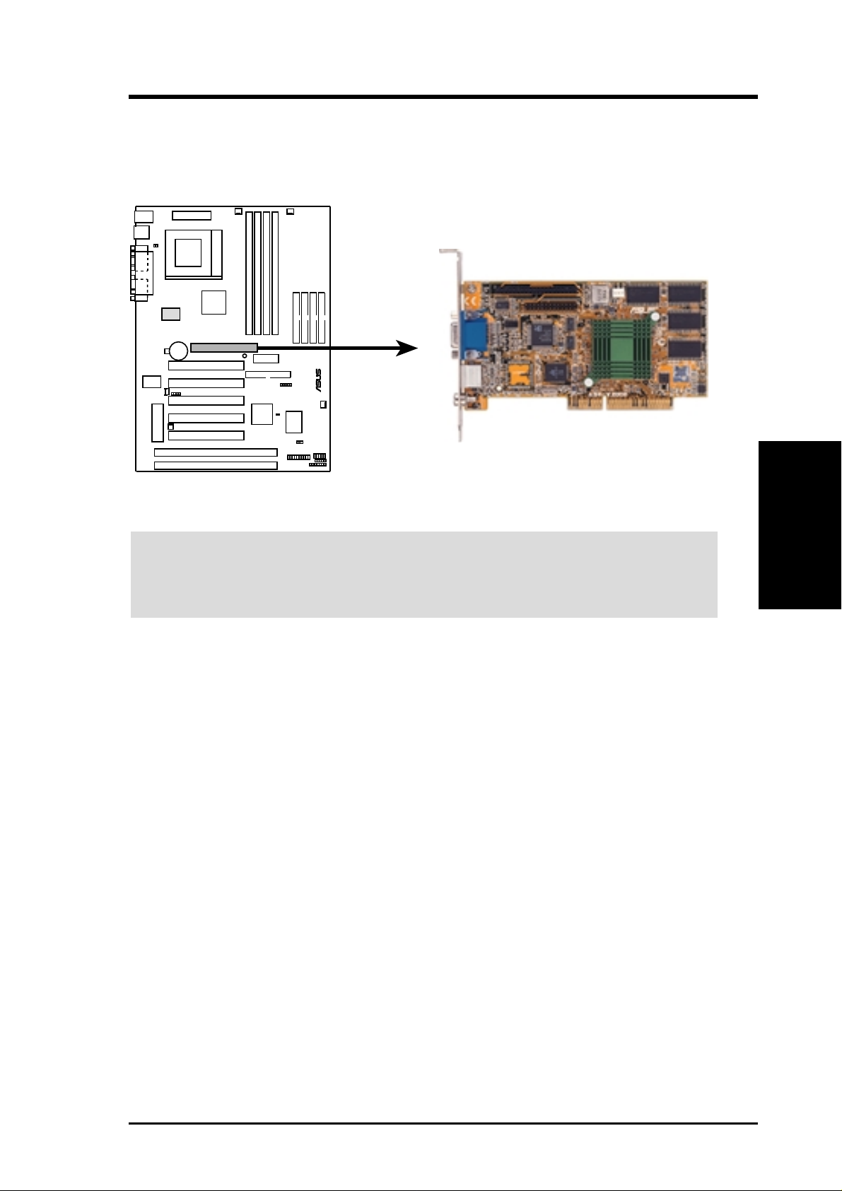
3.7.3 Accelerated Graphics Port (AGP)
This motherboard provides an accelerated graphics port (AGP) slot to support a new
generation of AGP graphics cards with ultra-high memory bandwidth.
®
CUBX-L/CUBX-E Accelerated Graphics Port (AGP)
WARNING! Make sure that you unplug your power supply when adding or re-
moving an expansion card or other system components. Failure to do so may cause
severe damage to both your motherboard and expansion cards (see 3.3 Hardware
Setup Procedure for more information).
3. H/W SETUP
Expansion Cards
ASUS CUBX-L/CUBX-E User’s Manual 29
3. H/W SETUP
Connectors
3. HARDWARE SETUP
3.8 Connectors
WARNING! Some pins are used for connectors or power sources. These are
clearly distinguished from jumpers in the Motherboard Layout. Placing jumper
caps over these connector pins will cause damage to your motherboard.
IMPORTANT: Ribbon cables should always be connected with the red stripe to
Pin 1 on the connectors. Pin 1 is usually on the side closest to the power connector on hard drives and CD-ROM drives, but may be on the opposite side on
floppy disk drives. Check the connectors before installation because there may
be exceptions. IDE ribbon cables must be less than 46 cm (18 in.), with the
second drive connector no more than 15 cm (6 in.) from the first connector.
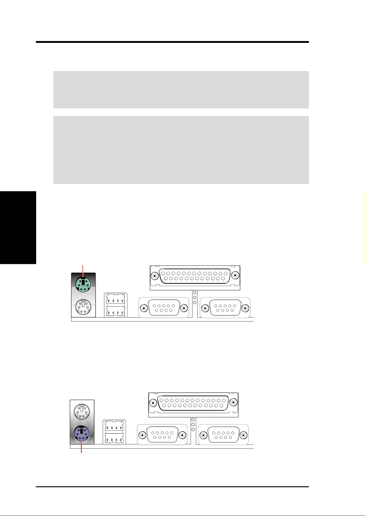
1) PS/2 Mouse Connector (Green 6-pin PS2KBMS)
The system will direct IRQ12 to the PS/2 mouse if one is detected. If one is not
detected, expansion cards can use IRQ12. See PS/2 Mouse Function Control
in 4.4 Advanced Menu.
PS/2 Mouse (6-pin Female)
2) PS/2 Keyboard Connector (Purple 6-pin PS2KBMS)
This connection is for a standard keyboard using an PS/2 plug (mini DIN). This
connector will not allow standard AT size (large DIN) keyboard plugs. You
may use a DIN to mini DIN adapter on standard AT keyboards.
PS/2 Keyboard (6-pin Female)
30 ASUS CUBX-L/CUBX-E User’s Manual
 Loading...