

Page 1

SERVICE OVERVIEW
T
Service Overview
Carefully read through this chapter for a look
at various components of the notebook and
necessary cautions and tools before
performing any service and repairs.
procedures, please be sure to read through the overview in this chapter
for component overview, cautions and tools to avoid any unwarranted
damages to the notebook’s hardware.
The following chapter includes:
• B1A Overview
• Components
• Precautions
• Appropriate Tools
Chapter
o provide the best service and support for the ASUS B1A Series,
we have provided the below information for technicians from
distributors and resellers to perform the complete notebook
disassembly and assembly. But before performing the
2 - 1
Page 2
OVERVIEW
SERVICE OVERVIEW
B1A Series Overview and Components
The ASUS B1A Series Notebook is a product combining the power of
Intel® Mobile CPU with uPGA2 mobile system. In this section, an
overview for the B1A, along with its components, will be presented.
B1A Overview
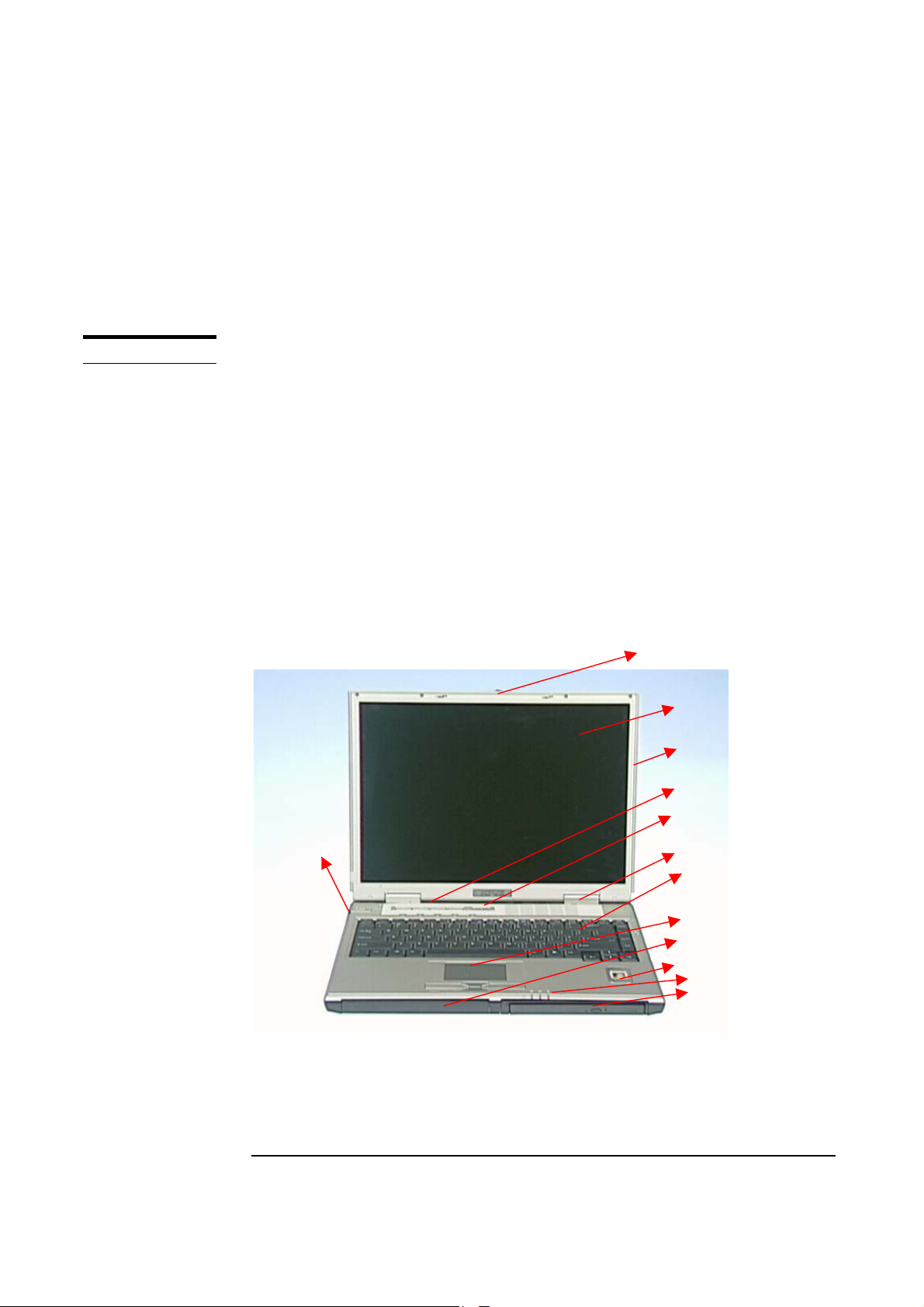
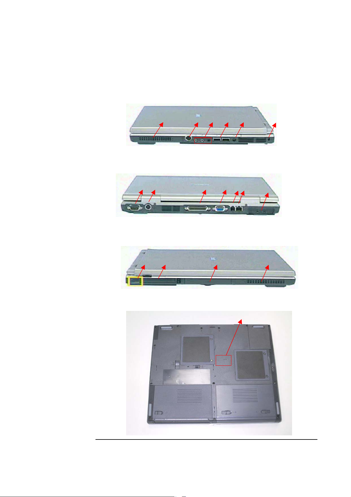
The illustrations below show the notebook’s overview from left front view,
right front view, rear view and bottom view. Most of the parts will be
discussed in this manual.
1. Latch
2. LCD display panel
3. LCD front cover
4. Instant key
5. Power Switch
6. Hinge cover
7. Keyboard
8. Touch Pad
9. Battery
10. Fingerprint
11. LED indicators
12. Multi-modules
13. Volume
Controller
14. Speaker
15. PS/2 Port
16. Audio Jacks
17. USB Ports
18. AC In
19. Kensington Lock
20. Serial Port
21. TV-out Port
22. Parallel Port
23. VGA Port
24. Modem Jack
25. LAN Jack
26. IEEE 1394 port
Or Docking Port
27. Infrared Port
28. PCMCIA Socket
29. HDD Module
30. Speaker
31. Reset Button
2
13
9
10
11
12
2 - 2
Page 3
SERVICE OVERVIEW
14 15 16 17 18 19
20 21 22 23 24 25
27 28 30 29
26
31
2 - 3
Page 4
SERVICE OVERVIEW
COMPONENTS
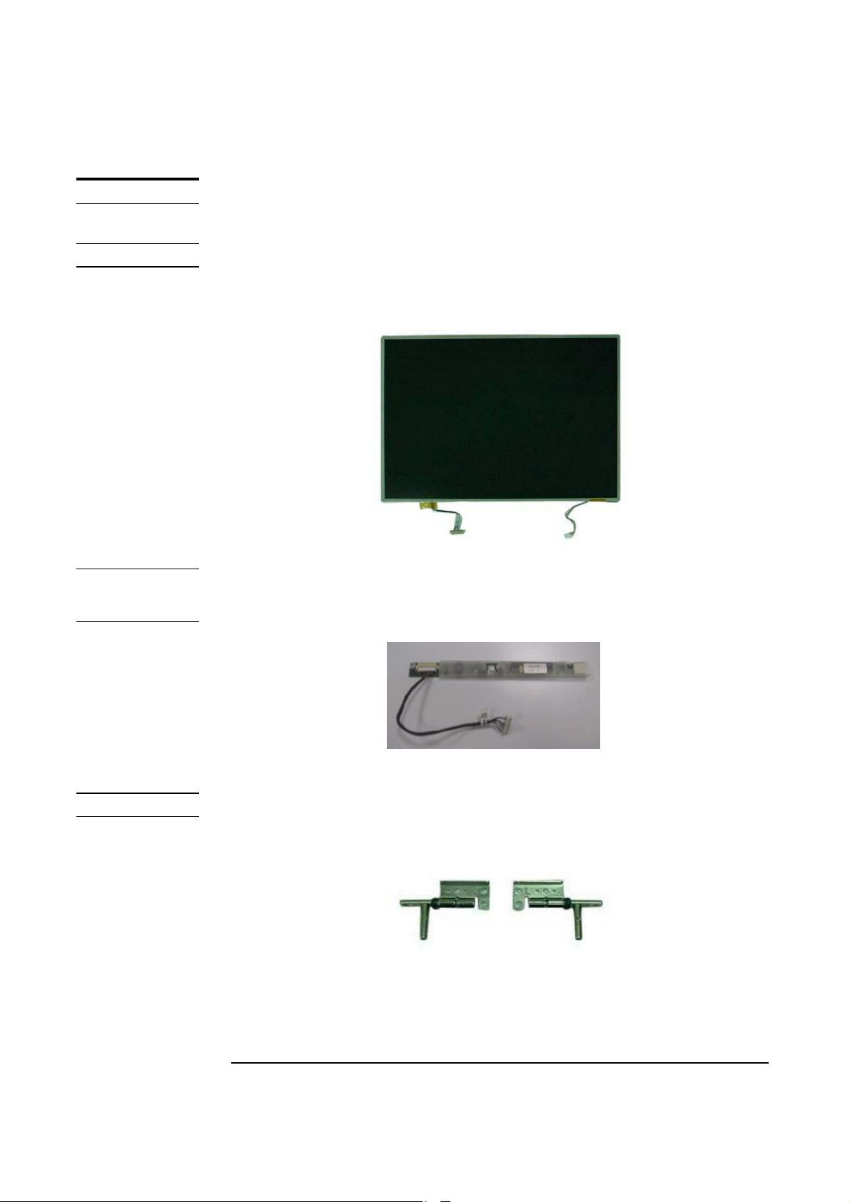
LCD PANEL
INVERTER
MODULE
Components
The illustrations below show the components of the B1A Series.
LCD Panel
The illustration below shows the LCD display panel. The B1A Series
notebook comes with 15” TFT.
Inverter Module
The illustration below shows the inverter board and cable, which is hidden
underneath the lower edge of the LCD front bezel.
LCD HINGES
LCD Hinge
The illustration below shows the LCD hinges that support the LCD module.
2 - 4
Page 5
SERVICE OVERVIEW
LCD
BRACKETS
LCD PANEL
FPC
LCD CASE
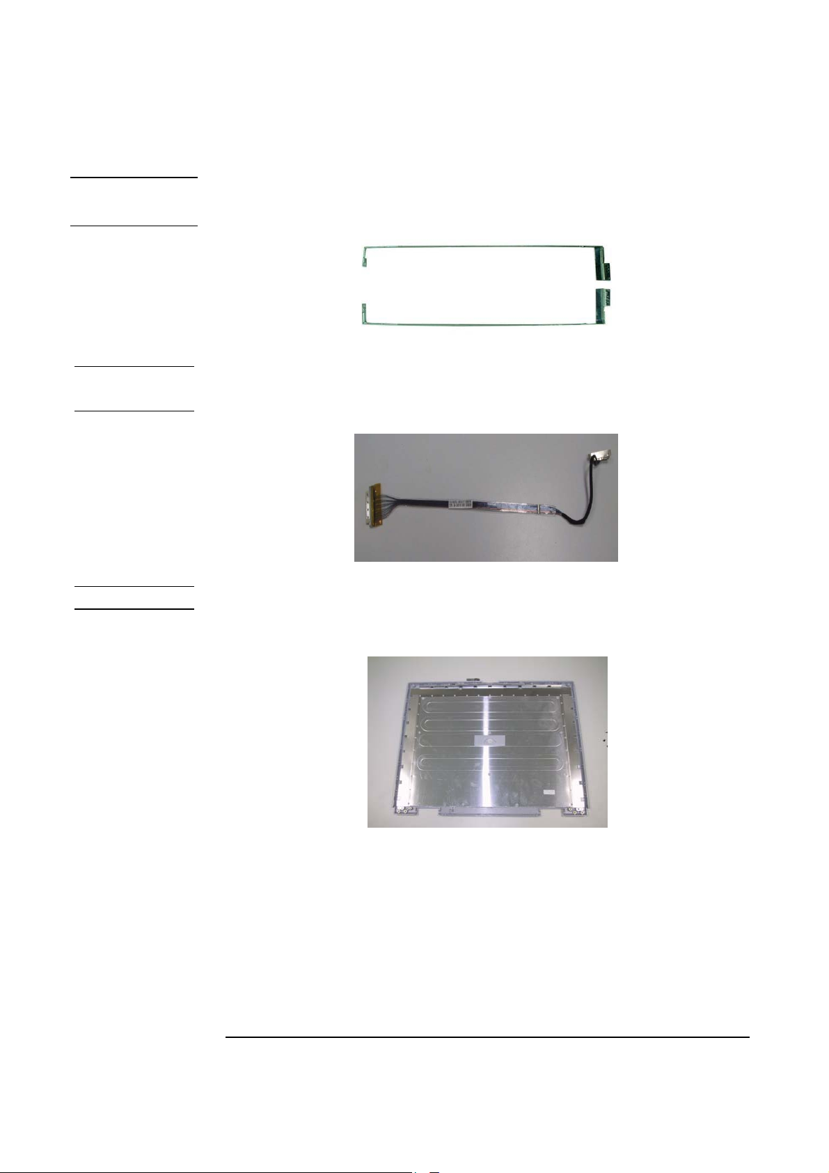
LCD brackets
The illustration below shows the LCD brackets.
LCD Panel FPC
The illustration below shows the LCD FPC It’s located in the lear of
LCD Panel.
LCD Case
The illustration below shows the LCD case that encloses the LCD panel,
inverter and hinge feet. Here is the LCD front cover and back cover.
2 - 5
Page 6

SERVICE OVERVIEW
KEYBOARD
TOUCHPAD
Keyboard
The illustration below shows the keyboard. It can be exchanged with
keyboard with different language layouts, such as U.S., Taiwanese,
German, Swedish, Italian, Russian, Japanese, Turkish, Czechoslovakian,
British and others.
Touch Pad Module
The illustration below shows the TouchPad bracket sub’sem that included
in Touch pad module.
TOP MODULE
Top Module
The illustration below shows the top module of the notebook.
2 - 6
Page 7

SERVICE OVERVIEW
MICROPHONE
FINGERPRINT
BROAD
BATTERY
PACK
Microphone
The illustration below shows the microphone.
FingerPrint board
The illustration below shows in the top case of the notebook.
Battery Pack
The illustration below shows the battery pack of the notebook. It’s
located at bottom left side of the notebook.
SWAP BAY
Swap Bay
The illustration below shows Swap bay of the notebook. It’s located at in
muilt-module of the notebook.
2 - 7
Page 8

SERVICE OVERVIEW
g
HDD DISK
DRIVE
HDD
HOUSING
Hard Disk Drive
The illustration below shows the 2.5” industry-standard HDD with 9.5mm
height.
HDD Housing
The illustration below shows the HDD housing.
HDD Bracket
PORTBAR &
IEEE-1394
BOARD
HDD Connector
HDD housin
Portbar & IEEE-1394 board
The illustration below shows the Portbar & IEEE-1394 board
2 - 8
Page 9

SERVICE OVERVIEW
UPGA2 CPU
CPU THERMAL
MODULE
uPGA2 CPU Module
The illustration below shows the Intel uPGA2 CPU Module, top and bottom
views. It’s located at the left corner under keyboard.
CPU Thermal module:
The illustration below shows the CPU Thermal module. It’s located on the
top of CPU.
MINI-PCI
CARD
Mini-PCI Card
The illustration below shows Mini-PCI Card.
2 - 9
Page 10

SERVICE OVERVIEW
RTC BATTERY
MEMORY
MODULE
MAINBOARD
MODULE
RTC Battery
The illustration below shows the RTC battery that keeps the internal clock
running.
Memory Module
The illustration below shows the industry-standard 144-pin SO-DIMM
SDRAM module for the notebook. It is installed under the keyboard of
the notebook.
Mainboard Module
The illustration below shows the mainboard module of the notebook.
BOTTOM
MODULE
Bottom module
The illustration below shows the bottom module of the notebook.
2 - 10
Page 11

SERVICE OVERVIEW
BOTTOM CASE
PCMCIA
MODULE
Bottom Case
The illustration below shows the bottom case of the notebook.
PCMCIA Module
The illustration below shows the PCMCIA Module, located at the Lear of
the Mainboard
.
AUDIO COVER
HINGE-COVER
Audio Covers
The illustration below shows the Audio cover of the notebook that located
at the right side of mainboard module.
Hinge-Cover
The illustration below shows the Hinge cover of the notebook.
2 - 11
Page 12

SERVICE OVERVIEW
MINI-PCI
CABLE
ICON MODULE
Mini-PCI cable
The illustration below shows the Mini-PCD cable .It’s connect between
the Mini-PCI Card and the Mainboard.
Icon Module
The illustration below shows the Audio bracket. It’s located at the Bottom
module.
SWITCH BOARD
ICON CABLE
Switch Board
The illustration below shows Switch Board. It’s located at the Icon
sub-assem.
Icon cable
The illustration below shows the Icon cable .It’s connect between the
Icon module and Mainboard.
2 - 12
Page 13

CAUTIONS
SERVICE OVERVIEW
Service Overview
Please pay special attention to the cautions below to prevent any damages
to the notebook and also please be sure to select the appropriate tools
described in this section to perform any services desired.
Precautions
Before you perform any service and/or repair on the notebook, please
follow the steps below first.
1. Be sure that the notebook is powered down.
2. Disconnect the AC plug from the right side of the notebook (no.1).
1
2.First unlock and hold the latch (No.1) here simultaneously.
Slide it out (No2).
3. Remove all rings, watches and any other metal objects from your
hands.
2
2 - 13
Page 14

TOOLS
CROSS
SCREW-
DRIVER
SERVICE OVERVIEW
4. Always wear a ground strap on your hand to protect the notebook
from static discharge.
Appropriate Tools
The illustrations below show the appropriate tools that should be used for
the notebook’s service and repair.
Phillips-head Screwdriver
Use a Phillips-head screwdriver to fasten/remove the K- or B-typed screws.
FLATHEAD
SCREW-
DRIVER
TWEEZERS
SPACER
SCREW-
DRIVER
Single-Slotted Screwdriver
Use a single-slotted screwdriver to lock/unlock the flexible cable
connector locks.
Tweezers
Use a pair of tweezers to remove/insert flexible cables.
Spacer Screwdriver
Use a spacer screwdriver to fasten/remove spacer screws or hex screws.
2 - 14
Page 15

SERVICE OVERVIEW
PLIERS
VACUUM
HANDLING
TOOL
MOLEX
CPU SOCKET
TOOL
Pliers
Use a pair of pliers to handle regular cables.
Vacuum Handling Tool
Use Vacuum handling tool to handle CPU.
Molex CPU Socket Tool
Use Molex CPU Socket tool to lock/unlock the Molex socket of CPU.
INSERTION
AND
EXTRACTION
TOOL FOR FPC
CONNECTOR
Width: 4.00mm Depth: 0.45+/-0.1mm The angle of tip: approximate 9 degree
Insertion and extraction tool for FPC connector
Use insertion and extraction tool for FPC connector to handle locking and
unlocking of FPC connectors.
2 - 15
 Loading...