

Page 1

B1A Hardware Technical Specification (Rev. 1.0)
Hardware Specifications
Get to know more about the B1 Series Notebook
with a detailed look at the hardware specifications.
ach item has its individual usage for you to understand the hardware
side of the notebook’s architecture.
E
Chapter
ASUSTek Confidential
Page 1 of 1
Page 2
B1A Hardware Technical Specification (Rev. 1.0)
Revision History:
DATE VERSION DESCRIPTION SECTION REMARK
Feb 2001 1.0 Initial Specification
ASUSTek Confidential
Page 2 of 2
Page 3

B1A Hardware Technical Specification (Rev. 1.0)
1. MARKETING SPEC. ..........................................................................................................................6
2. CHIPSET LIST.................................................................................................................................. 11
2.1. CPU......................................................................................................................................... 11
2.2. CHIPSET (TWISTER)-----NORTH-BRIDGE+GRAPHICS CHIP ......................................................12
2.3. DRAM MEMORY ....................................................................................................................12
2.3.1. EXPANSION MEMORY......................................................................................................12
2.4. BIOS ROM...............................................................................................................................13
2.5. SOUTH BRIDGE(VT8231)-----SOUTH-BRIDGE+SUPER I/O.........................................................13
2.6. CARDBUS CONTROLLER(OZ711E1)...........................................................................................13
2.7. EMBEDDED CONTROLLER(NS591) ............................................................................................14
2.9. AUDIO CODEC ‘97(CS4299)...................................................................................................14
2.10. AUDIO AMPLIFIER................................................................................................................... 15
3. KEY PARTS LIST ..............................................................................................................................16
3.1. DISPLAY ................................................................................................................................... 17
3.2. HARD DISK DRIVE ...................................................................................................................17
3.3. CD-ROM DRIVE......................................................................................................................18
3.4. DVD-ROM DRIVE .................................................................................................................. 18
3.5. TOUCH PAD ..............................................................................................................................18
3.6. KEYBOARD ..............................................................................................................................19
3.7. BATTERY..................................................................................................................................19
3.7.1. Main Battery.......................................................................................................................19
3.7.2. RTC Backup Battery ........................................................................................................... 19
3.8. AC/DC ADAPTER(ADP-60DB)----DELTA..............................................................................20
4. SYSTEM...........................................................................................................................................21
4.1. SYSTEM DIAGRAM................................................................................ 錯誤! 尚未定義書籤。
4.2. MAIN COMPONENTS BLOCK DIAGRAMS .......................................................................................21
4.3. SYSTEM RESOURCE ....................................................................................................................22
4.3.1. IRQ Map ............................................................................................................................. 22
4.3.2. PCI INT map.......................................................................................................................22
4.3.3. PCI bus master map ...........................................................................................................22
4.3.4. IDSEL .................................................................................................................................23
5. I/O PORT PIN ASSIGNMENT ..........................................................................................................24
5.1. CRT .........................................................................................................................................24
ASUSTek Confidential
Page 3 of 3
Page 4

B1A Hardware Technical Specification (Rev. 1.0)
5.2.
HARD DISK PIN ASSIGNMENT ......................................................................................................25
5.3. LCD PIN ASSIGNMENT ...............................................................................................................26
5.4. INTERNAL KEYBOARD PIN ASSIGNMENT .......................................................................................26
5.5. INTERNAL TOUCH PAD PIN ASSIGNMENT .....................................................................................27
5.6. BATTERY PIN ASSIGNMENT(JP29/JP28)......................................................................................28
5.7. DC IN JACK PIN ASSIGNMENT.....................................................................................................28
5.8. AUDIO JACK..............................................................................................................................28
5.8.1. HEADPHONE JACK..........................................................................................................28
5.8.2. MICROPHONE JACK........................................................................................................29
5.9. INVERTER PIN ASSIGNMENT ........................................................................................................ 29
5.10. LAN CONNECTOR PIN ASSIGNMENT...........................................................................................29
5.11. MODEM CONNECTOR PIN ASSIGNMENT......................................................................................29
6. POWER MANAGEMENT ................................................................................................................. 30
6.1. SYSTEM POWER PLAN ................................................................................................................. 30
6.2. POWER MANAGEMENT MODE .....................................................................................................30
6.2.1. Full-On mode......................................................................................................................30
6.2.2. Doze mode ..........................................................................................................................30
6.2.3. Stand by mode.....................................................................................................................30
6.2.4. Suspend to RAM mode (STR)..............................................................................................31
6.2.5. Suspend to disk mode (STD)............................................................................................... 31
6.2.6. Mechanical off mode (MOFF)............................................................................................31
6.3. PMU MODE TRANSITION EVENT .................................................................................................32
6.3.1. Lid switch............................................................................................................................33
6.3.2. Power button ......................................................................................................................33
6.4. DEVICE POWER MANAGEMENT................................................................................................... 34
6.4.1. Device PM control during STR mode.................................................................................35
6.4.2. Device PM control during STD mode.................................................................................36
7. MODULE SPECIFICATION............................................................................................................37
7.1. OVERALL SYSTEM ...................................................................................................................... 37
7.1.1. Board Assembly ..................................................................................................................37
7.1.2. Modules .............................................................................................................................. 37
7.2. MAIN BOARD ............................................................................................................................. 38
7.2.1. Main system module spec .............................................................................. 38
7.2.2. DC/DC spec...........................................................................................................39
7.2.3. Charger Spec........................................................................................................39
7.3. INVERTER BOARD ...................................................................................................................... 40
ASUSTek Confidential
Page 4 of 4
Page 5

B1A Hardware Technical Specification (Rev. 1.0)
7.4.
ADAPTER SPEC(DELTA-----ADP-60DB)...................................................................................40
7.4.1. Input....................................................................................................................................40
7.4.2. Output.................................................................................................................................40
7.4.3. Protection ...........................................................................................................................41
7.5. BATTERY SPEC ...........................................................................................................................41
MODEM SPEC. .........................................................................................................................................42
8. MISCELLANEOUS...........................................................................................................................43
8.1. INDICATORS ..............................................................................................................................43
8.2. POWER CORD LIST .....................................................................................................................44
8.3. SAFETY/ EMI APPLIANCE:.........................................................................................................44
ASUSTek Confidential
Page 5 of 5
Page 6
B1A Hardware Technical Specification (Rev. 1.0)
1. Marketing spec.
B1A Specification
Product Family B1A
Dimension 329X269X32mm(WXDXH)
Weight ~3.3Kg(Total system)
Color Silver
CPU Type Intel PIII w/256K/
Celeron w/128K
Speed PIII:700Mhz~1GMHz
Celeron:600~800MHz
Package Intel uPGA2 socketable
L2 Cache YES
Size 128 or 256 KB
Type PBSRAM
Memory Type SDRAM
Expansion Memory 256MB(Max.) SO-DIMM x 2 Slots
LCD Size 15.0” 15.0"
Resolution XGA SXGA+
Panel Type TFT TFT
Contrast Control None
Brightness Control Hot-key Control
HDD type 2.5" /9.5mm
Ultra DMA/33 or 66 YES with SMART supported
Size 10/20/30 GB
CD-ROM/DVD/CD-RW
(5.25” 12.7mm)
Chip Set VIA
North Bridge
(Including Graphics
chip)
South Bridge
(Including Super I/O
controller)
KBC NS87591(National
ROM 256k X 8
ASUSTek Confidential
24X CD-ROM/ 8X DVD/
4X CD-RW
Twister
VT8231
Semiconductor)
Page 6 of 6
Page 7
B1A Hardware Technical Specification (Rev. 1.0)
Graphic Accelerator
(S3 Savage4 exists in
Twister chip)
3D Single cycle 128-bit 3D
S3 Savage4
architecture
Controller S3 Savage4
Package
(Twister)
552 balls(35X35mm)
(Twister)
AGP Support 4X AGP
Video Memory Share Memory Architecture
TV(CHRONTEL 7009) YES , one S-Video port
PCMCIA O2Micro
Slot Type Type II x 2 or Type III X1
Controller OZ711E1
Card Bus Yes
ZV port Yes
Sound System
(Sound chip exists in
South Bridge VT8231)
Compatibility Hardware Sound Blaster Pro
FM synthesizer Yes
Speaker Stereo
PC99 Yes
Audio Amplifier Philips TDA8552TS
(2 X1.4W)
Mic Mono
Modem + LAN
(Using Mini-PCI Combo
Modem + LAN(Combo Card)
Card solution)
Modem(Combo Card) ESS Z2
Controller N/A(Depends on vendors)
Spec 56K
Jack RJ11
ACPI Yes
V.90 Yes
Wake-up on ring Yes
LAN(On Combo Card) ESS Z2
Jack RJ 45
Wake on LAN Yes
Controller N/A(Depends on vendors)
Internal Keyboard
ASUSTek Confidential
Page 7 of 7
Page 8
B1A Hardware Technical Specification (Rev. 1.0)
Vendor JME Color = Slate Gray
2
Key 88 Keys(W/Z MS-Windows
function keys)
Function Key 12 Function Keys
Hot Key Function 11 Hot Keys
Suspend To RAM Fn + F1 Suspend Switch
Programmable App2 Fn + F3
Programmable App3 Fn + F4
Brightness Up Fn + F5
Brightness Down Fn + F6
LCD only Fn + F7
LCD/CRT Switch Fn + F8
TV only Fn + F9
PC Speaker Mute Fn + F10 Mute/Un-Mute
PC Speaker Volume Fn + F11 Volume Up
PC Speaker Volume Fn + F12 Volume Down
Instant Keys
E-mail Direct button
Internet Browser Direct button
M-Mode
(Special function
for longer battery life)
Direct button
Programmable App1 Direct button
Status Indication LEDs (Machine Base** x6)
Power Status* Yes (Green when Power on.
Flash (1Hz) when in SUSPEND
mode. Off when power off.)
Battery Charge
Status
Yes ( ON: orange when
charging, Blinking: when battery
low.; OFF: when battery is
absent or fully charged.)
HDD/CD-ROM LED Yes (green while accessing)
Caps Lock LED Yes (green)
Number Lock LED Yes (green)
Scroll Lock LED Yes (green)
Audio Mute lndicator Yes(green)
M-Mode Indicator Yes(green)
Pointing Device
Built-In Touch Pad(Synaptics)
Glide Pad Yes
Right Button Yes
Left Button Yes
ASUSTek Confidential
Page 8 of 8
Page 9
B1A Hardware Technical Specification (Rev. 1.0)
Scroll up button Yes
Scroll down button Yes
Function Control
Power On Button Yes
Lid Switch Yes
Sound Volume Yes (Uses VR)
I/O Port
CRT Yes (15p D-sub)
PS/2 Mouse and/or
Yes (Y-Cable)
K/B
IrDA Port SIR/FIR Support X1
Fax/Modem Yes X1
COM port Yes X1
LAN JACK Yes X1
Line Out Jack Yes/Stereo X1
Mic In Jack Yes/Mono X1
S/PDIF Jack Yes X1
USB port Yes 2 Ports.
LPT port Yes X1
S-Video Port Yes X1
IEEE-1394 Port Yes X1(On daughter
Board)
DC-In Yes X1
Heat Solution
Heat Sink Yes
FAN Support Yes
AC Adaptor Yes
Input AC 90-270V 47/63Hz
Output DC 19V , 3.1A, ~60W
Battery Pack 9 Cells
Type Li-ION(5400mAH/~60W)
1st Battery Li-Ion
2nd Battery Yes
Charging time Smart Battery Charger
Machine ON ~2.5Hrs(85% up) (estimative value)
Machine OFF ~2 Hrs(85% up) (estimative value)
Battery Life Li-ION (1800mAH)
Estimative value ~2.5 Hrs. Depends on testing
environment/AP
Power Management Insyde
Suspend/Resume Yes
ASUSTek Confidential
Page 9 of 9
Page 10
B1A Hardware Technical Specification (Rev. 1.0)
LCD Close/Open Yes
Hibernation (S2D) Yes
Thermal Control Yes
ACPI Yes
Security
Password Yes, BIOS booting user
password protection
Finger-Print security
(Option)
Option
Security Lock Kensington Lock Hole
S/W
Install OS ME/2000/XP
Flash BIOS Yes 2M(256KX8)
Drivers
CDROM Driver Yes
PCMCIA Driver Yes
AUDIO Driver Yes
VIA chipsets Driver
Yes
(4-in-1 Driver)
Glide Pad Driver Yes
Modem+LAN Driver
Yes
(Combo Card)
LOGO
Microsoft PC99 Yes
Winkey Yes
ASUSTek Confidential
Page 10 of 10
Page 11
B1A Hardware Technical Specification (Rev. 1.0)
2. Chipset List
Chipset Summary Table.
Function B1A HW ACPI/PC98
CPU Intel PIII/ Celeron Not required
SRAM (L2 Cache) Pipeline Burst SRAM (On-die)
PIII(256KB)/Celeron(128KB)
Core Logic
Twister YES
(N/B+VGA)
MEMORY SDRAM Not required
BIOS ROM 2M(256KX8) Not required
Not required
Core Logic
VT8231 YES
(S/B+SIO+Audio+
S/FIR)
PCMCIA O2Micro OZ711E1 YES
AUDIO CODEC Crystal CS4299 YES
AUDIO AMPLIFIER Philips TDA8552TS Not required
KB CONTROLLER NS87591 YES
IEEE-1394 On Daughter Board YES
LAN+MODEM
(Combo Card)
N/A
(Depends on vendors)
YES
2.1. CPU
Processor compatibility:
Type :
Processor frequency:
Construction method:
Supply voltage:
Function feature:
Intel Pentium III CPU
Pentium III (256K)/ Celeron (128K) L2 cache
PIII: 700/~1GhzMHz; Ce: 600~800 MHz
μ-PGA2
Core:1.6V~1.7V /1.35
1. Integrated L2 cache (128k/256k)
2. Integrated thermal 1 diode
3. Low-power GTL+ processor system bus
4. 0.18u process technology
5. High performance with lower power consumption.
6. Speedstep Technology support
ASUSTek Confidential
Page 11 of 11
Page 12

B1A Hardware Technical Specification (Rev. 1.0)
2.2. CHIPSET (Twister)-----North-Bridge+Graphics Chip
Function:
Vendor:
Parts Number:
Package:
1. High performance SMA North Bridge:Integrated
VIA Apollo Pro133A and S3 Savage4 in a single
Chip.
2. 64-bit advanced memory controller supporting
PC100/PC133 SDRAM and VCM.
3. 66/100/133Mhz CPU Front Side Bus(FBS).
4. Integrated Savage4 2D/3D Video Accelerator.
5. Optimized share memory Architecture(SMA)
For Video Memory.
6. Full internal AGP 4X performance.
7. High quality DVD video playback.
8. Integrated 2-channel 110Mhz LVDS interface.
9. ACPI 1.0 and PCI Bus Power Management 1.1
Compliant.
10. 2.5V Core and Mixed 3.3V/5V Tolerant and GTL+
I/O.
VIA
Twister
35X35mm PBGA package with 552 balls
2.3. DRAM MEMORY
2.3.1. EXPANSION MEMORY
Number of sockets:
Bus:
Refresh rate:
Supply voltage:
Functional features:
Hardware features:
Two 144 pin SO-DIMM sockets
64-bit data path
4K refresh cycles/ 64ms
3. 3V
1. Synchronous operations (positive edges of clocks)
2. Pipeline architecture
3. Auto refresh and self refresh
4. Programmable Mode Register
5. LVTTL compatible inputs and outputs
6. Burst stop function
Easy removable and exchangeable for user.
ASUSTek Confidential
Page 12 of 12
Page 13

B1A Hardware Technical Specification (Rev. 1.0)
2.4. BIOS ROM
ROM Type:
Package:
Supply voltage:
Erase/program:
Serviceability:
256K x 8 CMOS Flash Memory
PLCC 32-Lead
5V
10,000 erase/program cycles minimum
End user refreshable design (software re-flash)
2.5. South Bridge(VT8231)-----South-Bridge+Super I/O
Function:
Vendor:
Parts Number:
Package:
1. Integrated Super I/O (FDC,LPT,COM and FIR).
2. Integrated SoundBlaster Pro/Multi-channel.
3. UltraDMA-33/66/100 Master Mode EIDE
controller.
4. 4 ports USB controller ,RTC ,Serial IRQ ,SMBus
support.
5. Plug and Play ,ACPI ,Power Management Support.
6. Temperature, voltage, and FAN speed monitoring.
7. ACPI v1.0 Compliant
8. APM v1.2 Compliant
9. 0.30um, 3.3V, Low Power CMOS Process.
VIA
VT8231
27X27 mm 376 pin BGA
2.6. CardBus Controller(OZ711E1)
Function:
Hardware features:
1. Using a Smart Cardsensing technology OZ711E1
Can dynamically reconfigure its internal
functionality to support either a PC card or a ISO
7816-1,-2,-3, compliant smart card.
2. Integrated Card Bus Controller.
3. Support Ultra Zoomed Video mode.
4. ACPI-PCI Bus Power Management Interface Spec.
Rev 1.1 Compliant.
5. Compliant with PCI spec. v2.2, PC Card standard
7.0 and JEIDA 4.1.
6. Support 2 PCMCIA 1.0 and JEIDA 4.2 R2 cards or
2 CardBus cards or a passive Type II PC Card
smart card holder.
7. Reads and Writes to all ISO 7816-1,-2,-3 smart
Cards.
Vendor:
Parts Number:
Package:
ASUSTek Confidential
O2Micro
OZ711E1B
208 pin Mini-BGA
Page 13 of 13
Page 14

B1A Hardware Technical Specification (Rev. 1.0)
2.7. Embedded Controller(NS87591)
Function features:
1. Follow LPC interface Spec. Rev. 1.0.
2. PC01 Rev 0.3, and ACPI 1.0b Compliant.
3. 16-bit RISC core, with 2 Mbyte address space, and
running at up to 20Mhz.
4. Share BIOS flash memory(internal and/or external).
5. Y2K-compliant RTC.
6. 84 GPIO ports with a variety of wake-up events.
7. Extremely low current consumption in Idle mode.
8. JTAG-based debugger interface.
9. Built-in ADC(A-to-D Converter)—10 bit resolution.
10. Built-in DAC(D-to-A Converter)---8-bit resolution.
11. CompactRISC CR16B 16-bit embedded RISC
Processor core.
Vendor:
Parts Number:
Package:
National Semiconductor
NS87591
128-pin LQFP package
2.9. AUDIO Codec ‘97(CS4299)
Function features:
1. Fully Compliant AC97 Compliant.
2. 20-bit Stereo Digital to Analog Converters.
3. 18-bit Stereo Analog to Digital Converters.
4. High-quality pseudo-Differential CD input.
5. Meets or exceeds the Microsoft PC99 Audio
Performance requirements.
6. S/PDIF digital audio output.
7. CrystalClear 3D Stereo Enhancement.
Vendor:
Parts Number:
Package:
ASUSTek Confidential
Crystal
CS4299
48-pin TQFP
Page 14 of 14
Page 15

B1A Hardware Technical Specification (Rev. 1.0)
2.10. AUDIO Amplifier
Function features:
Vendor:
Parts Number:
Package:
1. 2 X 1.4W BTL audio amplifiers with digital volume
control and headphone sensing.
2. Low sensitivity for EMC radiation.
3. Standby mode controlled by CMOS compatible
Levels.
4. Thermally protected.
Philips
TPA8552TS
20-pin SSOP
ASUSTek Confidential
Page 15 of 15
Page 16

B1A Hardware Technical Specification (Rev. 1.0)
y
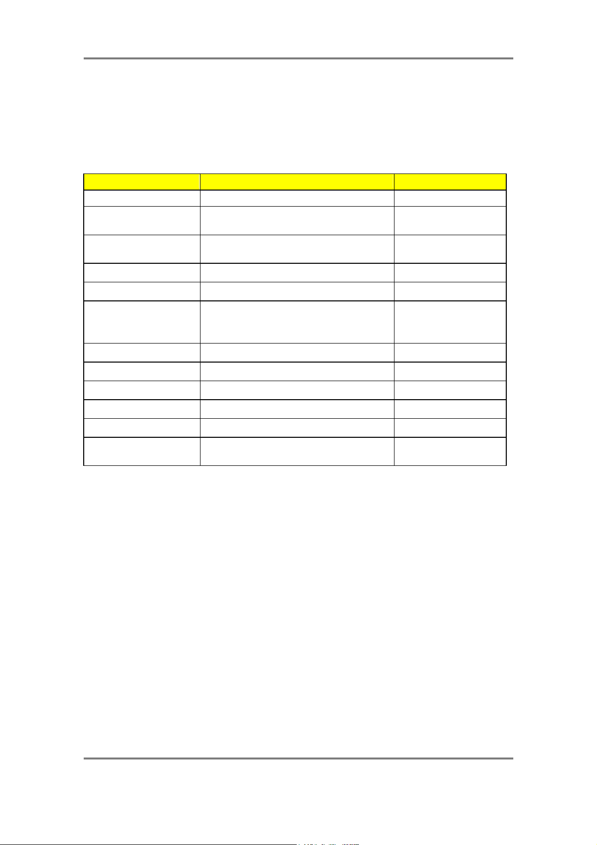
3. Key parts list
Key Parts Summary:
Project B1A Key parts List
Priorit
Vendor Model No. Part No. Remark
1 2 3
1
2
LG LP150X1-G2 CP
24X CD-ROM
1 TEAC CD-224E-B92 17-030717245
2 TOSHIBA XM-7002BC 17-030715246
h9.5mm HDD
1
1
1
2
2
2
Mini-PCI Modem&LAN Combo Card
1
2
3
3
Battery Pack
1
3 GLV B13S3P
Keyboard
1
GlidePad (Support Scroll Up/Down)
1
AC Adapter
1
1 Liton
INVERTER
1 SUMIDA PWB-LV10129T/B1
FDD
1 TEAC FD-05HG-5744 REV:2.0 17-021222042
2 MITSUMI D353F3-Z69-5072 17-021226032
15" TFT XGA
HITACHI TX38D85VC1CAA
Samsung LT150X3-124
3 CHI MEI(CMO)
15" TFT SXGA+
PANASONIC ECTCB30QAF
HITACHI TX38D95VC1CAA
SAMSUNG LTN150P1-L01
CHI MEI(CMO)
Fujitsu MHK-2050AT 5GB 17-013111111
Fujitsu MHM-2100AT 10GB 17-013121111
Fujitsu MHM-2200AT 20GB
Fujitsu MHM-2050AT 5GB 17-013111110
TOSHIBA MK1016GAP 10GB
TOSHIBA MK2016GAP 20GB
Fujitsu MHM-2150AT 15GB 17-013126110
Billionton ESS Z2
ACTION Tec MC 100RPMI
ACTION Tec MC 100DP8-1A
3COM 3CN3AC1556
SMP 906-2240(P)906-2230(S)
JME KB-JME-K990162A1
Synaptics TM41PDG351
Delta ADP-70LB
Rev. 1.4
17-013127110
17-013121800
17-013127800
ASUSTek Confidential
Page 16 of 16
Page 17

B1A Hardware Technical Specification (Rev. 1.0)
3.1. Display
[Option:
15.0” XGA TFT]
Technology:
Size:
Resolution:
Pixel Pitch:
Display Colors :
Vendor:
Active color (TFT: Thin Film Transistor)
15.0”
XGA (1024*768)
0.297mm x 0.297mm
262,144
SAMSUNG LT150X3-126
LG LP150X1-G2 CP
3.2. Hard Disk Drive
[Option:]
Form factor:
Capacity:
Height:
Interface:
Functional features:
Hardware features:
2.5 inch
10/20 GB
9.5 mm
Enhanced IDE conforming to ATA-4
Power Management APM 1.1 and 1.2
(standby/suspend)
LBA-modes
Standard I/O addresses: 1F0h to 1F7h and 3F6h
Support of minimum IRQ 14
Support of at least 3 DMA channels, if DMA is
supported
Easily removable and exchangeable for user’s
future upgradability
ASUSTek Confidential
Page 17 of 17
Page 18

B1A Hardware Technical Specification (Rev. 1.0)
3.3. CD-ROM Drive
Form factor:
Speed:
Height:
Interface:
Functional features:
Hardware features:
Vendor/Model:
5.25 Inch
x24 or higher
12.7mm
IDE (ATAPI)
Power Management APM 1.1 and 1.2
(standby/suspend)
Standard I/O addresses:
Support of minimum IRQ
TEAC(CD-224E-A93)
3.4. DVD-ROM Drive
Form factor:
Speed:
Height:
Interface:
Functional features:
Vendor/Model:
5.25 Inch
Max 8X (DVD)/ Max. 24X (CD)
12.7mm
IDE (ATAPI)
Fast 100 ms Random Access time (DVD)
Fast 95 ms Random Seek time (DVD)
Support CD multi-session Disc Spec, CD-R and
CD-RW Disc Spec.
Windows 99 spec compliant
Low power consumption
Software Volume Control
Toshiba/ SD-C2502
3.5. Touch Pad
Vendor/Model Synaptics:TM41PDG-351
Dimensions:
Sensor effective areas:
Interface:
X/Y position resolution:
Customizing:
Functional features: Accurate positioning
65 mm(W) x 49 mm(H) x 2.82 mm(T)
62.5 mm(W) x 46.5 mm(H)
PS/2
40 points / mm (graphics mode)
Custom color can be printed on the sensor pad.
Low fatigue pointing action
Low power consumption
Software configurable
Scanner function for signature
Low profile, compact size and low weight
ASUSTek Confidential
Page 18 of 18
Page 19

B1A Hardware Technical Specification (Rev. 1.0)
A
3.6. Keyboard
Compatibility:
Functional features:
Hardware feature:
MS-Windows 98
Standard Notebook-Keyboard
MF2-Layout
Simultaneously use of internal and external
keyboard
Easily to assemble or disassemble
Dimensions: (H) 267.44mm x (V) 108.8 mm
Type:
Total travel:
Key top:
Language versions:
Key switch Membrane
2.5 ±0.3 mm
BS material, TANPO printing with UV hardening
English, Japanese, Chinese, Korean and
European etc.,
3.7. Battery
3.7.1. Main Battery
Purpose:
Gas-gauge:
Chemistry:
Voltage:
Capacity:
Power:
Vendor:
Duration:
Charge Method:
Charging Source:
Gas-gauge:
3.7.2. RTC Backup Battery
Main power supply battery
SMBus interface
Li-ion rechargeable battery
Nominal 11.1V (= 3.6V cell 3pcs in serial, 3pcs in
parallel)
Typical 1800mAH(Single-cell)
60Whrs
Panasonic , Samsung
~2.5 hour(Estimative value)
Fast Charge: 2hour (while System off)—85% up
AC Adapter
BENCHMARQ bq2060H
Purpose:
Chemistry:
Voltage:
Capacity:
Vendor:
ASUSTek Confidential
Backup the RTC/CMOS data
while AC adapter off & Main Battery removed
Coin cell Li-ion battery
Nominal 3V
200mAH
Sony
Page 19 of 19
Page 20

B1A Hardware Technical Specification (Rev. 1.0)
3.8. AC/DC Adapter(ADP-60DB)----DELTA
The notebook can be powered either by an external AC adapter or by an
internal battery pack. The AC adapter is used as power source for the DC/DC
converter and as constant current source for the battery pack.
Input Requirements:
AC line voltage:
AC line current:
AC line frequency
Efficiency
Output requirements:
Output-Voltage
Output-Current
Ripple voltage
Power cord:
DC Cable length:
Regulatory:
EMI:
Safety:
.Dimension: 114.5X49.5X29mm
90V to 270V AC, Full Range
<=1.5A
47Hz to 63Hz
>=85%
+19V DC
Max. 3.1A (Approximately 60W)
<=500mVp-p
Plug to the adapter
1800+-50mm
FCC Class B, CISPR 22 Class B
UL,TUV/GS,CE,PSB,c-UL,FIMKO……etc.
ASUSTek Confidential
Page 20 of 20
Page 21

B1A Hardware Technical Specification (Rev. 1.0)
4. System
4.1. Main components block diagrams
ASUSTek Confidential
Page 21 of 21
Page 22

B1A Hardware Technical Specification (Rev. 1.0)
4.2. System resource
4.2.1. IRQ Map
IRQ# Description
IRQ 0 System Timer
IRQ 1 Keyboard
IRQ 2 [Cascade]
IRQ 3 FIR
IRQ 4 Available
IRQ 5 Audio
IRQ 6 Available
IRQ 7 Available
IRQ 8 RTC Alarm
IRQ 9 ACPI
IRQ10 Available
IRQ11 Audio/ VGA/ LAN/ MODEM/ CARDBUS/ USB
IRQ12 PS/2 Mouse
IRQ13 FPU
IRQ14 Hard Disk Drive/ CD-ROM
IRQ15 Available
4.2.2. PCI INT map
INT Description
INTA VGA
INTB MINI PCI (Modem+LAN)
INTC CARDBUS
INTD DOCK
4.2.3. PCI bus master map
REQ Description
REQ0 RESERVED
REQ1 MINI-PCI
REQ2 CARDBUS
REQ3 DOCK
ASUSTek Confidential
Page 22 of 22
Page 23

B1A Hardware Technical Specification (Rev. 1.0)
4.2.4. IDSEL
IDSEL CHIPSET
AD28 VT8231(SOUTH-BRIDGE)
AD27 MINI PCI
AD26 CARDBUS
ASUSTek Confidential
Page 23 of 23
Page 24

B1A Hardware Technical Specification (Rev. 1.0)
5. I/O port pin assignment
No FUNCTION DESCRIPTION
1. .CRT Display (Analog)
2. .USB Universal Serial Bus (UHCI)
3. .FIR Fast Infrared (4Mb)
4. .DCIN Adapter Input
5. .LAN/FAX/MODEM (10/100 Mb Ethernet and K56flex modem)
6. .MIC MONO
7. .LINE OUT STEREO
5.1. CRT
Vendor Part No. Pin No.
FOXCONN FOXCONN/DZ11A
91-L8-HT
No PIN ASSIGEMENT(by: sort) DESCRIPTION
1 ROUT
(analog)
2 GOUT
(analog)
3 BOUT
(analog)
4 NC Option
5 GROUND : Ground
6 RED Return (ground) : Ground
7 GREEN Return (ground) : Ground
8 BLUE Return (ground) : Ground
9 NC OPTION
10 SYNC Return (ground) : Ground
11 NC NC
12 DDC_DAT_OUT DDC monitor data
13 HSYNC_OUT CRT Horizontal Sync this output is the
14 VSYNC_OUT CRT Vertical Sync this output is the
15 DDC_CLK_OUT DDC monitor clock
15 Pin
(DIP)
Red this DAC analog output drives the
CRT interface.
Green this DAC analog output drives the
CRT interface.
Blue this DAC analog output drives the
CRT interface.
Horizontal sync pulse for the CRT
monitor.
Vertical sync pulse for the CRT Monitor.
ASUSTek Confidential
Page 24 of 24
Page 25

B1A Hardware Technical Specification (Rev. 1.0)
5.2. Hard disk pin assignment
No. Signal Description Type
1 HDD_RST# Reset primary disk I
2 GND Ground
3 HDD_D7 Primary disk data 7 I/O
4 HDD_D8 Primary disk data 8 I/O
5 HDD_D6 Primary disk data 6 I/O
6 HDD_D9 Primary disk data 9 I/O
7 HDD_D5 Primary disk data 5 I/O
8 HDD_D10 Primary disk data 10 I/O
9 HDD_D4 Primary disk data 4 I/O
10 HDD_D11 Primary disk data 11 I/O
11 HDD_D3 Primary disk data 3 I/O
12 HDD_D12 Primary disk data 12 I/O
13 HDD_D2 Primary disk data 2 I/O
14 HDD_D13 Primary disk data 13 I/O
15 HDD_D1 Primary disk data 1 I/O
16 HDD_D14 Primary disk data 14 I/O
17 HDD_D0 Primary disk data 0 I/O
18 HDD_D15 Primary disk data 15 I/O
19 GND Ground
20 NC NC
21 IDE_PDRQ Primary DMA request O
22 GND Ground
23 IDE_PIOW# Primary disk IO write I
24 GND Ground
25 IDE_PIOR# Primary disk IO read I
26 GND Ground
27 IDE_PIORDY Primary disk IO channel ready O
28 CSEL_HD Cable Select
29 IDE_PDACK# Primary DMA acknowledge I
30 GND Ground
31 IRQ14 Primary disk interrupt O
32 NC NC
33 IDE_PA1 Primary disk address 1 I
34 HDD_DIAG Diagnostics status I/O
35 IDE_PA0 Primary disk address 0 I
36 IDE_PA2 Primary disk address 2 I
37 IDE_PCS#1 Primary disk chip select for 100 range I
38 IDE_PCS#3 Primary disk chip select for 300 range I
39 HD_DASP# I/O
40 GND Ground I
41 VCC_IDE +5v power supply PWR
42 VCC_IDE +5v power supply PWR
43 GND Ground
44 VCC_IDE +5v power supply PWR
ASUSTek Confidential
Page 25 of 25
Page 26

B1A Hardware Technical Specification (Rev. 1.0)
5.3. LCD pin assignment
No.
5
6
8
9
11
12
14
15
19
20
22
23
25
26
28
29
1,2
3,4,7,10,13,
16,21,24,
27,30
17,18
Signal Description Type
LVDS_UTX0- LVDS Transmitter signal(-) I
LVDS_UTX0+ LVDS Transmitter signal(+) I
LVDS_UTX1- LVDS Transmitter signal(-) I
LVDS_UTX1+ LVDS Transmitter signal(+) I
LVDS_UTX2- LVDS Transmitter signal(-) I
LVDS_UTX2+ LVDS Transmitter signal(+) I
LVDS_UCLK- LVDS Transmitter signal(-) I
LVDS_UCLK+ LVDS Transmitter signal(+) I
LVDS_LTX0- LVDS Transmitter signal(-) I
LVDS_LTX0+ LVDS Transmitter signal(+) I
LVDS_LTX1- LVDS Transmitter signal(-) I
LVDS_LTX1+ LVDS Transmitter signal(+) I
LVDS_LTX2- LVDS Transmitter signal(-) I
LVDS_LTX2+ LVDS Transmitter signal(+) I
LVDS_LCLK- LVDS Transmitter signal(-) I
LVDS_LCLK+ LVDS Transmitter signal(+) I
LCD_VCC3 Power 3.3V for LCD I
Ground Ground GND
NC NC NC
5.4. Internal keyboard pin assignment
No Signal Description Type
1 KEYIN0 Keyboard matrix IN0 IN
2 KEYIN1 Keyboard matrix IN1 IN
3 KEYIN2 Keyboard matrix IN2 IN
4 KEYIN3 Keyboard matrix IN3 IN
5 KEYIN4 Keyboard matrix IN4 IN
6 KEYIN5 Keyboard matrix IN5 IN
7 KEYIN6 Keyboard matrix IN6 IN
8 KEYIN7 Keyboard matrix IN7 IN
9 KEYOUT0 Keyboard matrix OUT0 OUT
10 KEYOUT1 Keyboard matrix OUT1 OUT
11 KEYOUT2 Keyboard matrix OUT2 OUT
12 KEYOUT3 Keyboard matrix OUT3 OUT
13 KEYOUT4 Keyboard matrix OUT4 OUT
14 KEYOUT5 Keyboard matrix OUT5 OUT
15 KEYOUT6 Keyboard matrix OUT6 OUT
ASUSTek Confidential
Page 26 of 26
Page 27

B1A Hardware Technical Specification (Rev. 1.0)
16 KEYOUT7 Keyboard matrix OUT7 OUT
17 KEYOUT8 Keyboard matrix OUT8 OUT
18 KEYOUT9 Keyboard matrix OUT9 OUT
19 KEYOUT10 Keyboard matrix OUT10 OUT
20 KEYOUT11 Keyboard matrix OUT11 OUT
21 KEYOUT12 Keyboard matrix OUT12 OUT
22 KEYOUT13 Keyboard matrix OUT13 OUT
23 KEYOUT14 Keyboard matrix OUT14 OUT
24 KEYOUT15 Keyboard matrix OUT15 OUT
5.5. Internal Touch Pad Pin assignment
No Signal Description Type
1 NC Reserved
2 NC Reserved
3 NC Reserved
4 NC Reserved
5 NC Reserved
6 NC Reserved
7 NC Reserved
8 PUSB_P3- Reserved for fingerprint function I
9 PUSB_P3+ Reserved for fingerprint function I
10 VCC3 Power 3.3V I
11 POWER_LED# Power status indicator I
12 CHG_LED# Battery charger status indicator I
13 VSUS3 Power 3.3V I
14 EMAIL_LED# E-mail status indicator I
15 GND Ground G
16 GND Ground G
17 INMSCLK For Touch pad I
18 INMSDATA For Touch pad I
19 VCC5_SW Power 5V I
20 VCC5_SW Power 5V I
ASUSTek Confidential
Page 27 of 27
Page 28

B1A Hardware Technical Specification (Rev. 1.0)
5.6. Battery pin assignment(JP29/JP28)
No Signal Description Type
1 GND Ground O
2 VBAT1/2 Battery input/output voltage I/O
3 SMC_BAT1/2 SMCLK for battery I/O
4 SMD_BAT1/2 SMData for battery I/O
5 TEMP_BAT1/2 Battery temperature thermal pin I
6 GND Ground O
5.7. DC in Jack pin assignment
No Signal Description Type
1 AD_IN0 Adapter input voltage I
2 GND Ground G
3 GND Ground G
5.8. Audio Jack
5.8.1. HEADPHONE JACK
No Signal Description Type
1 GND GROUND G
2 GND GROUND G
3 LINE_L LINE-IN LEFT SOUND I
4 NC RESERVED
5 LINE_R LINE-IN RIGHT SOUND I
6 NC RESERVED
7 NC RESERVED
8 GND GROUND G
ASUSTek Confidential
Page 28 of 28
Page 29

B1A Hardware Technical Specification (Rev. 1.0)
5.8.2. MICROPHONE JACK
No Signal Description Type
1 GND GROUND
2 GND GROUND
3 MICIN External Microphone input signal I
4 INTMIC Internal Microphone input signal I
5 NC RESERVED
6 NC RESERVED
7 NC RESERVED
8 GND GROUND
5.9. Inverter pin assignment
No Signal Description Type
1,2 VCC5_SW Inverter board power supply(+5V) I
4,6 VCC3_SW Inverter board power supply(+3.3V) I
3 PANEL_ID0 Panel Type detection 0 O
5 PANEL_ID1 Panel Type detection 1 O
7 SMC_SB2 SMCLK for Inverter I/O
8 SMD_SB2 SMData for Inverter I/O
9 BLIGHT_ON Backlight on/off control pin I
10 BRIGHTNESS Brightness control pin I
11 GND GROUND
12 GND GROUND
5.10. LAN Connector Pin Assignment
No
1 GLED_N 7 TERMI2
2 GLED_P 8 RD3 TD+ 9 TERMI3
4 TD- 10 TERMI4
5 RD+ 11 YLED_N
6 TERMI1 12 YLED_P
Signal
No
Signal
5.11. Modem Connector Pin Assignment
1. Modem Connector Pin Assignment
Pin No Remark
1. TIP
2. RING
ASUSTek Confidential
Page 29 of 29
Page 30

B1A Hardware Technical Specification (Rev. 1.0)
6. Power management
6.1. System power plan
Power Group
VCC5 MAX1632 MIC2564A,MIC2526,MAX3243
VCC3 MAX1632 VT8231,SO-DIMM SOCKET,
12V MAX1632 MIC2564A
VSUS5 LP2951 MAX3243,LP2951
VSUS3
VCC5_SW SI3456DV MAX4490,INVERTER,PACS1284…etc.
VCC3_SW SI3456DV GCL,TWISTER,VT8231……..etc.
RTCVCC Sub BAT. VT8231,NS591
VCPU_CORE MAX1717 CPU
VCC2.5 MAX1714 Twister, Clock generator
Power
Control By
MIC5245-
3.3BM5
Controlled Devices
SI4835,OZ711E1,TWISTER,CLOCK GEN.
VT8231,NS591,MINI-PCI SOCKET…etc.
6.2. Power management mode
6.2.1. Full-On mode
All system devices are not power managed and the system can respond to
applications with maximum performance.
6.2.2. Doze mode
The CPU clock is slow down but all other devices are full-on.
6.2.3. Stand by mode
A suspend state where all motherboard components are still powered-on
except for the system clock generator device. The PCI and CPU buses are
driven to the inactive idle state. The system memory is powered and
ASUSTek Confidential
Page 30 of 30
Page 31

B1A Hardware Technical Specification (Rev. 1.0)
refreshed by the memory bridge, and the graphics frame buffer is powered
and refreshed by the graphic chip. The system provides a 32Khz clock
(SUSCLK) in this suspend mode to support refresh of these memory
subsystems. Only an enabled “resume event” can bring the system out of
the stand by state. The south bridge also provides a resume timer that
allows the system to resume after a programmed time has elapsed.
6.2.4. Suspend to RAM mode (STR)
A suspend state where all motherboard components are powered-off. The
CPU/L2 and PCI busses are powered off. All devices connected to the
CPU/L2 and PCI busses must either be powered-off or isolate their bus
interfaces. The system memory is powered and refreshed by the memory
bridge, and the graphics frame buffer is powered and refreshed by the
graphics chip. The system provides a 32 kHz clock (SUSCLK) in this
suspend mode to support refresh of these memory subsystems. Only an
enabled “resume event” can bring the platform out of the suspend to RAM
(STR) state.
6.2.5. Suspend to disk mode (STD)
A suspend state where the context of the entire system is saved to disk, all
motherboard components are powered-off, and all clocks are stopped. Any
enabled “resume event”, such as PowerBTN or RTC, can bring the platform
out of the suspend to disk (STD) state.
6.2.6. Mechanical off mode (MOFF)
All power except the RTC has been removed from the system.
ASUSTek Confidential
Page 31 of 31
Page 32

B1A Hardware Technical Specification (Rev. 1.0)
6.3. PMU mode transition event
The following table summarizes the entry events and wake-up events of each
power management mode.
Power State Entry Event Wake up Event
Doze Doze Time out
Stand by
Stand by Time out
STR Suspend Time out
STR hot key pressed
Lid close
Predefined Mem/IO range
access
Ring Indicator Keystroke
Mouse movement
IRQ 1-15
Predefined Mem/IO range
access
Battery Warning
Battery Low
Ring Indicator
Keystroke (Int.,Ex. and USB
keyboard )
Mouse movement
Schedule Alarm
Ring Indicator
Keystroke ( Int. KB )
Schedule Alarm
STD Suspend Time out
STD hot key pressed
Battery Low
Power Button
Ring Indicator (internal Modem )
Schedule Alarm
Lid close
ASUSTek Confidential
Page 32 of 32
Page 33

B1A Hardware Technical Specification (Rev. 1.0)
6.3.1. Lid switch
Display mode State Lid close Lid open
LCD
Full on LCD OFF No action
Stand by LCD OFF No action
STR/STD LCD OFF No action
CRT
Full on No action No action
Stand by No action No action
STR/STD No action No action
SIMUL
Full on CRT No action
Stand by No action No action
STR/STD No action No action
LCD display will be shut down while closing LCD.
6.3.2. Power button
Power button can power on/ off the system.
ASUSTek Confidential
Page 33 of 33
Page 34

B1A Hardware Technical Specification (Rev. 1.0)
6.4. Device Power management
Power state of local devices table
Power State
Doze Stand By STR STD
Component
CPU
Stop
Stop Clock Power Off Power Off
Grant
Twister ON Stop Clock PowerOff
Power Off
(except
VSUS25)
VT8231 ON ON
Power Down
(except
RTCVCC&
Power Off
(except
RTCVCC)
VDDS)
DRAM ON Self Refresh Self Refresh Power Off
CDROM(DVD) ON On Power Off Power Off
HDD ON On Power Off Power Off
KBC ON On Power down Power Off
PCMCIA ON On Power down Power Off
LCD Backlight ON On Power Off Power Off
LAN ON On On Power Off
Modem ON On On Power Off
ASUSTek Confidential
Page 34 of 34
Page 35

B1A Hardware Technical Specification (Rev. 1.0)
6.4.1. Device PM control during STR mode
Device
Power Down
Description
Controlled by
CPU Hardware Controlled by VT8231,SUSB#
(SUSP_12V) pin
TWISTER Hardware Power Off , SUSP_DLY#
VT8231 Hardware Power Off , SUSP_DLY#, except
VDDS ,USBVDD, RTCVCC
HDD Hardware Power Off ,SUSP_DLY#
CD-ROM Hardware Power Off , SUSP_DLY#
PCMCIA Controller Hardware Power Off , SUSP_DLY#
Combo Card Hardware +3.3VAUX on,VCC5 and +5VA off
IR Module Hardware Power Off , SUSP_DLY#
LCD Panel Hardware Power Off , LCDPWREN
Back light Hardware Power Off , SUSP_DLY#
Clock Generator Hardware Uses PD# to power down
Keyboard Controller
(NS591)
Hardware VDD off and RTCVCC,VCC, AVCC
is on
L2 Cache
(CPU Inside)
Hardware Power Off
ASUSTek Confidential
Page 35 of 35
Page 36

B1A Hardware Technical Specification (Rev. 1.0)
6.4.2. Device PM control during STD mode
Device
Power Down
Description
Controlled by
CPU Hardware Power off
Twister Hardware Power off
VT8231 Hardware Power off
HDD Hardware Power off
CD-ROM Hardware Power off
PCMCIA Controller Hardware Power off
Combo Card Hardware Power Off
Audio AMP Hardware Power off
IR Module Hardware Power off
LCD Panel Hardware Power off
Back light Hardware Power off
Clock Generator Hardware Power off
Keyboard Controller
Hardware Power off
(NS591)
L2 Cache Hardware Power off
ASUSTek Confidential
Page 36 of 36
Page 37

B1A Hardware Technical Specification (Rev. 1.0)
7. Module Specification
7.1. Overall System
The notebook system consists of the following PCB assembly and
modules.
7.1.1. Board Assembly
Main Board Main System, DC/DC and Charger
Inverter Board Voltage transformer for LCD
Switch Board LED indicators, Power button, Instant keys
Gauge Board Battery status
Dock connector For IEEE-1394 board or docking or
port-replicator
Combo Card Modem + LAN(On Mini-PCI)
Touch Pad & LED Board For LED indicators, Touch pad , and
Finger-print function(Option)
AC Adapter AC to DC power supply
7.1.2. Modules
No. Items Remark
1 Hard Disk Drive Module
2 SO-DIMM Module
3 Li-ion Battery Pack
4 CD-ROM(DVD) Module
5 Floppy Drive Module
P.S CD-ROM and Floppy Drive are swapped.
ASUSTek Confidential
Page 37 of 37
Page 38

B1A Hardware Technical Specification (Rev. 1.0)
7.2. Main board
7.2.1. Main system module spec
Feature: Clock generator
SO-DIMM sockets
VT8231 LPC bus support
PC/AT compatible system (RTC, DMA, INT,
Timer, … etc)
IDE controller with PIO Mode 4 & Ultra-33.
PCMCIA /ZV /Cardbus controller & their
sockets
I/O peripheral controller (FDC, COM,
LPT, …etc)
Audio controller(VT8231 Inside)
I/O connectors
Graphics chipset Savage4(Twister Inside)
Keyboard Controller(NS591)---LPC Bus
Power control, DC/DC
IR transmit & receive signals
[To Processor] <ref. To Processor >
[To Charger ]
Function:
Connector:
Signals:
Connection to Battery Charger
Battery power
SUYIN/25033A-06G1
SMC_BAT2, SMD_BAT2, TEMP_BAT2
VBAT2
ASUSTek Confidential
Page 38 of 38
Page 39

B1A Hardware Technical Specification (Rev. 1.0)
7.2.2. DC/DC spec.
Controller : MAX1632(For system)/MAX1717(For CPU)
MAX1714A(For TWISTER)
Input voltage : 8-20V
Output voltage/current :
Voltage Current Ripple Regulation
5V (VCC5) 4A N/A +-3%
3.3V (VCC3) 4A N/A +-3%
12V (12V) 100mA N/A +-5%
2.5V(VCC2.5) 4A N/A +-1%
1.5V (VTT) 2.7A N/A N/A
VCPU_CORE 22A N/A +-1.5%
Support OVP
Support OCP
7.2.3. Charger Spec.
Charger spec.
Controller : MAX1772
Input voltage : 19.0V(Typical)
Support Li-ion Battery Charge
Charger current :
Input : Adapter
Contain Min Typ. Max
Charge current (system off) N/A 2.7A N/A
Charge current (system on) Depend on system power
consumption---Uses total power
Pre-charger current ~Approximately 200mA
Ripple & Noise ~500mV
Efficiency ~91.82%
2.7A
ASUSTek Confidential
Page 39 of 39
Page 40

B1A Hardware Technical Specification (Rev. 1.0)
7.3. Inverter Board --------- *****Uncertified*****
Inverter spec
Input voltage: 5V
Output current: 4mA(max)
Start voltage : 1200Vrms(min)
Efficiency : 80%(min)
Brightness adjust by input control duty cycle.
Support output short protection
Frequency : 30~70KHz
Output connector for CCFT:
Pin no I/O Description
1 Input/ Output High voltage
2 Input/ Output Return
Brightness control duty : 43-100%
7.4. Adapter spec(DELTA-----ADP-60DB)
7.4.1. Input
Input voltage : 90~270VAC , Full range
Input frequency : 47~63Hz
Inrush current : <=60Ap-p/100Vac , <=120Ap-p/240Vac
Efficiency : >=85%
7.4.2. Output
70 W power output
Output Voltage/Current : 19V(+-5%)/3.68A
Ripple : <=500mVp-p
ASUSTek Confidential
Page 40 of 40
Page 41

B1A Hardware Technical Specification (Rev. 1.0)
7.4.3. Protection
OVP : 24V(max.)
SCP : Yes---No broken, No smoke
OCP : 5A(max.)
OTP: Yes
7.5. Battery spec
Battery pack capacity:
Vendor Cells Voltage Capacity Watts
Li-ion Panasonic 9 10.8V 5400mAh 58.32W
Li-ion Samsung 9 10.8V 5400mAh 58.32W
Battery warning and low percentage(Li-ion):
Battery warning = 10%
Battery low = 4%
Gauge controller setting: (BENCHMARQ bq2060H)
Li-ion:
Charging voltage: 12.6V(Typical)
Charging efficiency: >90%
ASUSTek Confidential
Page 41 of 41
Page 42

B1A Hardware Technical Specification (Rev. 1.0)
7.6. Combo Card Spec.(LAN+Modem)
LAN spec.
Feature:
Vendor
Model
Package
- 10 Mb/s and 100 Mb/s operation
- PCI local bus single-chip fast Ethernet
controller
- Support Wake-On-LAN function and
remote wake-up.
- Compliant to PCI revision 2.2
- Chipset:
- Interface: PCI bus
- IEEE 802.3 10BASE-T and
100BASE-TX (CSMA/CD) support
Billionton
ESS Z2
Mini PCI Combo Card Module
Modem spec.
Feature:
- Support Ring wake up function
- V.90 for highest internet connect
- Modem Data speed 56Kbps
- Modem modulation format : V.90
[To Main board ]
Connector:
Vendo:r
Model:
Mini-PCI Connector
Billionton
ESS Z2/Combo Card
rates.
PCM
ASUSTek Confidential
Page 42 of 42
Page 43

B1A Hardware Technical Specification (Rev. 1.0)
8. Miscellaneous
8.1. Indicators
Power LED
Feature:
Type :
Color:
Indication:
Location:
Show System power status
SMD Type LED
Green
Green when Power on. Flash (1Hz) when in
SUSPEND mode. Off when power off.
On Switch Board
Charging LED
Feature:
Type :
Color:
Indication:
Location:
IDE LED
Keyboard LED
Feature:
Type :
Color:
Location:
Feature:
Type :
Color:
Location:
Show Battery status
SMD Type LED
ON: orange when charging, Blinking: when
battery low.; OFF: when battery is absent or
fully charged.
On Switch Board
On: While HDD/CDROM Read/Write access
SMD type LED
Green
Switch Board (in front of System)
On: While CAPS, Num Lock, Scroll Lock activate
SMD Type LED
Green
Switch Board (in front of System)
ASUSTek Confidential
Page 43 of 43
Page 44

B1A Hardware Technical Specification (Rev. 1.0)
Mute LED
Feature:
Type :
Color:
Location:
While Audio Muted
SMD type LED
Green
Switch Board (in front of System)
M-Mode LED
Feature:
Type :
Color:
Location:
While Marathon-Mode Enable(For Longer-Battery
Life)
SMD type LED
Green
Switch Board (in front of System)
8.2. Power cord list
Where Description Vendor
US P-CORD 1.8m 125V 7A UL 2-PIN WS-027-T Well shin
UK P-CORD 1.8m 250V 2.5A UK 2-PIN
Well shin
WS-027-T
Japan P-CORD 1.8m 125V 7A T-MARK 2-PIN
Well shin
WS-027-T
Europe P-CORD 1.8m 250V 2.5A EUR 2-PIN
Well shin
WS-027-T
Austria P-CORD 1.8m 250V 2.5A AUS 2-PIN
Well shin
WS-027-T
South
Asia
P-CORD 1.8m 125V 7A WS016+WS027
WS-027-T
Well shin
8.3. Safety/ EMI Appliance:
Agency
Approval
EMI
Safety UL, CSA or CUL, NEMKO-CB (Norway)
Telecomm. FCC Part 68 (USA), DOC (Canada), JATE
EMC CE Mark (Europe)
BCIQ (Taiwan)
FCC Class B Certified (USA & Canada)
VCCI (Japan)
TUV, CE Mark (Europe)
? Dentori (Japan)
? C-Tick (Australia)
(Japan), AUSTEL (Australia),
TELEPERWIT(New Zealand)
CTR-21 (EU)
ASUSTek Confidential
Page 44 of 44
Page 45

B1A Hardware Technical Specification (Rev. 1.0)
Other
Requirements
Industry
Standards
Compliance
SPA Energy Star Compliance
Designed for Windows 95/98 and Windows NT
Logo
(Compliance with Microsoft PC98)
ASUSTek Confidential
Page 45 of 45
 Loading...