

Page 1

UPGRADE & REPLACEMENT
Upgrade & Replacement
Follow the individual procedures in this
chapter to perform the notebook’s upgrade
and replacement of various major
components.
sus T9A Series Notebook is not an all-in-one product, which
means there are more options for you to upgrade to. The key
A
CD-RW, CPU module, and mini PCI card.
In order to avoid redundancy, please refer to chapters 3 and 4 of this
manual for repeated and reused disassembly and assembly procedures,
such as keyboard & heat sink replacement, which is used by several
different procedures in this chapter. Be sure to follow the safety
instructions described in Chapter 2 to safeguard the notebook
against any potential damages. For any other components not
covered in this chapter, which you need to replace, please refer to
Chapters 3 and 4 for detailed disassembly and assembly and perform
necessary procedures accordingly.
This chapter includes the following items:
• HDD Upgrade & Replacement
• Memory Upgrade & Replacement
• CPU Upgrade & Replacement
• Multi-Modules (CD/DVD-ROM/CD-RW/FDD/2
• Mini PCI Card Replacement
upgradeable and replaceable items include the Battery module,
main memory module, HDD, FDD module, CD-ROM, DVD-ROM,
Replacement
Chapter
5
nd
HDD) Upgrade &
5 - 1
Page 2
UPGRADE & REPLACEMENT
HDD
HDD Upgrade & Replacement
The T9A Series Notebook uses an industry-standard 2½” HDD with IDE interface.
You can replace the HDD to any capacity of your choice within our approval and
prior test.
First, remove AC-power and battery.
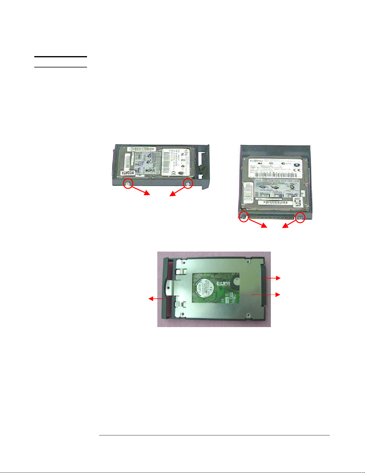
1. Remove HDD module (Refer to p.3-3).
2. Disassemble HDD module by unscrewing 4 screws (No.1, M3*4(K)
W-NI) on both sides, 2 screws (No.2 [M2*6(B) B-NI, NY] on back
side, and lifting HDD holder away.
3. Lift HDD Bracket away.
4.Remove HDD connector away carefully.
HDD
Holder
HDD
Connector
HDD
Bracket
HDD Replacement
3. Place HDD connector, bracket and holder carefully.
4. Place HDD housing on a new HDD and assemble the module by
securing 4 screws (No.1, M3*4(K) W-NI) on both sides, 2 screws
(No.2 [M2*6(B) B-NI, NY] on back side.
5. Install the new HDD module (Refer to p.4-15).
5 - 2
Page 3

UPGRADE & REPLACEMENT
MEMORY
Memory Upgrade & Replacement
The B1A Series Notebook comes standard with 128MB of RAM. There is
one expansion SODIMM socket for you to upgrade the total memory up
to 384MB with a 256MB module.
First, remove AC-power and battery.
1.Remove Memory module (Refer to p3-3).
2.If there is an existing memory, remove it by opening the latches (No.
1), which will pop the module up to a 45° angle, and then pulling out
the module in that angle (No. 2).
1
2
45∘
1
Memory Replacement
1.Insert new memory at the angle of 45 degrees, and press down (No.
3) until it clicks into the latches (No. 4).
2. Install the new memory module (Refer to p.4-15).
4
3
45∘
4
5 - 3
Page 4

UPGRADE & REPLACEMENT
MODULES
CPU
MULTI-
CPU Upgrade
The B1A Series Notebook comes standard with a Intel®’s µPGA2 Socket
on the motherboard, which means it can support all µPGA2 CPUs up to
1G MHz.
First, remove AC-power and battery.
Removing CPU
1.Unscrew 2 screws, and lift the memory cover away (Refer to p3-3
Removing Memory).
2.Unscrew 1 screw and remove mylar pad.
Push the Icon Module forward to the right side.
Lift it up and separate Icon cable carefully (Refer to p3-3
Removing ICON Module).
3. Unscrew 1 screw on the bottom of the notebook, lift up the
keyboard and lay it on the Touch Pad (Refer to p3-4 Removing
Keyboard).
4. Remove CPU (Refer to p3-5).
Installing CPU module
1.Install new CPU (Refer to p4-12).
2. Place keyboard and Secure 1 screw on the bottom of the
notebook (Refer to p4-13 Placing Keyboard).
3.Connect Icon cable to Icon module and place the Icon module it.
Push it to the left side, Secure 1 screw and place mylar pad (Refer
to p4-14 Placing ICON Module).
4.Screw 1 screw, insert the cover and fit it.
Screw 2 screws (Refer to p4-15 Installing Memory).
Multi-Modules (CD/DVD-ROM/CD-RW/FDD/2nd
HDD) Upgrade & Replacement
First, remove AC-power and battery.
Remove Multi-Modules (Rerer to p3-2 Removing CD-ROM/DVD/CD-
RW/FDD module).
Multi-Modules replacement
Install the new Multi-Modules (Rerer to p4-16 Installing CDROM/DVD/CD-RW/FDD module).
5 - 4
Page 5

UPGRADE & REPLACEMENT
MINI PCI
CARD
REPLACEMENT
MINI PCI CARD REPLACEMENT
First, remove AC-power and battery.
1.Unscrew 2 screws (M2*3L(K) B-NI, NY) and lift the cover away
(Refer to p3-3 Removing HDD).
2.Remove Mini PCI Card (Refer to p3-11 Removing Mini PCI Card).
Mini PCI Card Replacement
1.Place Mini PCI card (Refer to p4-7 Mini PCI Card assembly)
2.Insert the cover and fix it, screw 2 screws (M2*3L(K) B-NI,
NY)(Refer to p4-16 Install HDD).
5 - 5
 Loading...