

Page 1

ASSEMBLY PROCEDURE
A
Assembly Procedure
Please follow the information provided in this section to perform
the complete assembly procedure of the notebook. Be sure to
use proper tools described before.
Chapter
Chapter
fter you have completed the previous chapter of complete disassembly,
please follow this chapter to assemble the notebook back together. This
chapter describes the procedures of the complete notebook assembly.
The assem bly procedure consists of the following steps:
• LCD Module Assembly
• Top Module Assembly
♦
Fingerprint board & Touchpad assembly
• Main board Module Assembly
• Bottom Module Assembly
• Assemble of Top & Bottom Module
• Assemble of LCD & Top Module
• CPU Module Assembly
• Icon Module Assembly
♦
Installing Keyboard
♦
Installing ICON Module
• Removable Modules
♦
Installing Memory
♦
Installing CD-ROM/CD-RW/DVD/FDD drive module [2nd HDD is
optional]
♦
Installing HDD
♦
Installing Battery
4 - 1
Page 2
ASSEMBLY PROCEDURE
LCD MODULE
ASSEMBLY
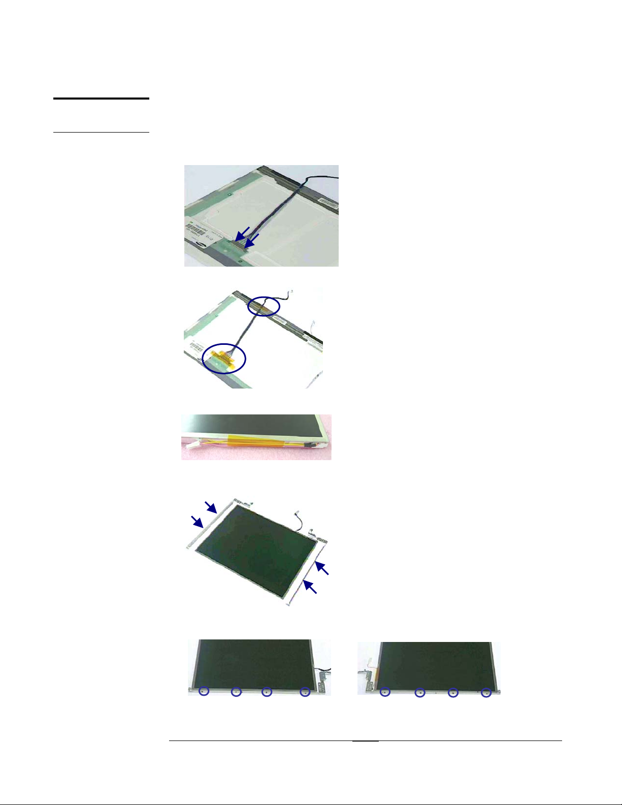
LCD Module assembly
The illustrations below show how to assemble the LCD module. The module contains
the LCD panel, inverter, hinge feet and LCD case.
1.Insert the LCD coaxial cable.
2.Fix 3 Labels here.
3.Fix the label on the cable.
4.Place the 2 brackets.
5.Screw 4 screws on the right bracket and 4 screws on the left bracket
4 - 2
Page 3
ASSEMBLY PROCEDURE
3
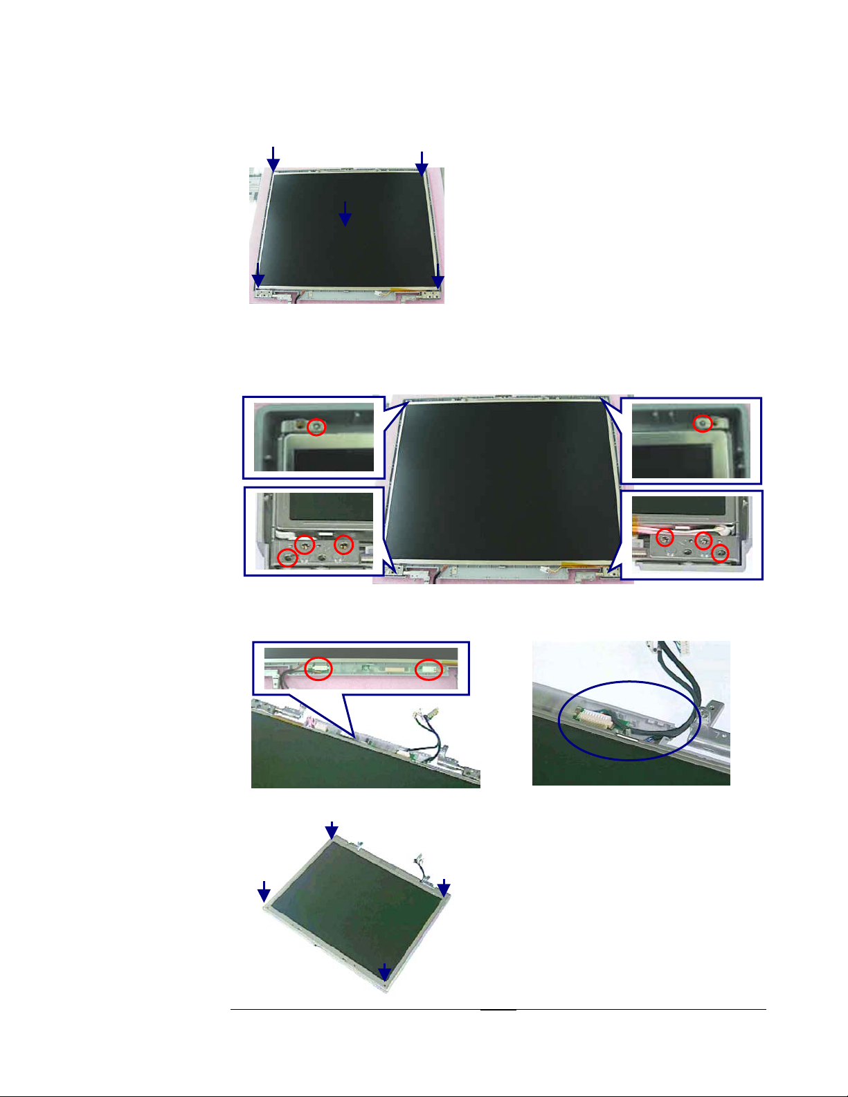
6.Place LCD Panel on the back cover carefully.
7.Screw 3 screws (No.1 [M2.5*6L(B) B-NI, NY]).
8.Screw 3 screws (No.2 [M2.5*6L(B) B-NI, NY]).
9.Screw 1 screw (No3 [M2*3L(K) B-NI, NY]).
10.Screw 1 screw (No4 [M2*3L(K) B-NI, NY]).
4
3
1
2
11.Insert Inverter cable on Inverter Board (No.1) and LCD Power cable (No.2).
12.Place the Inverter Board and Fix coaxial & Inverter cable (No.3).
1
2
13.Place and fix on Front cover, and notice the position of the latches.
4 - 3
Page 4
TOP M O D U L E
A S S E M B L Y
FINGERPRINT
BOARD
ASSEMBLY
ASSEMBLY PROCEDURE
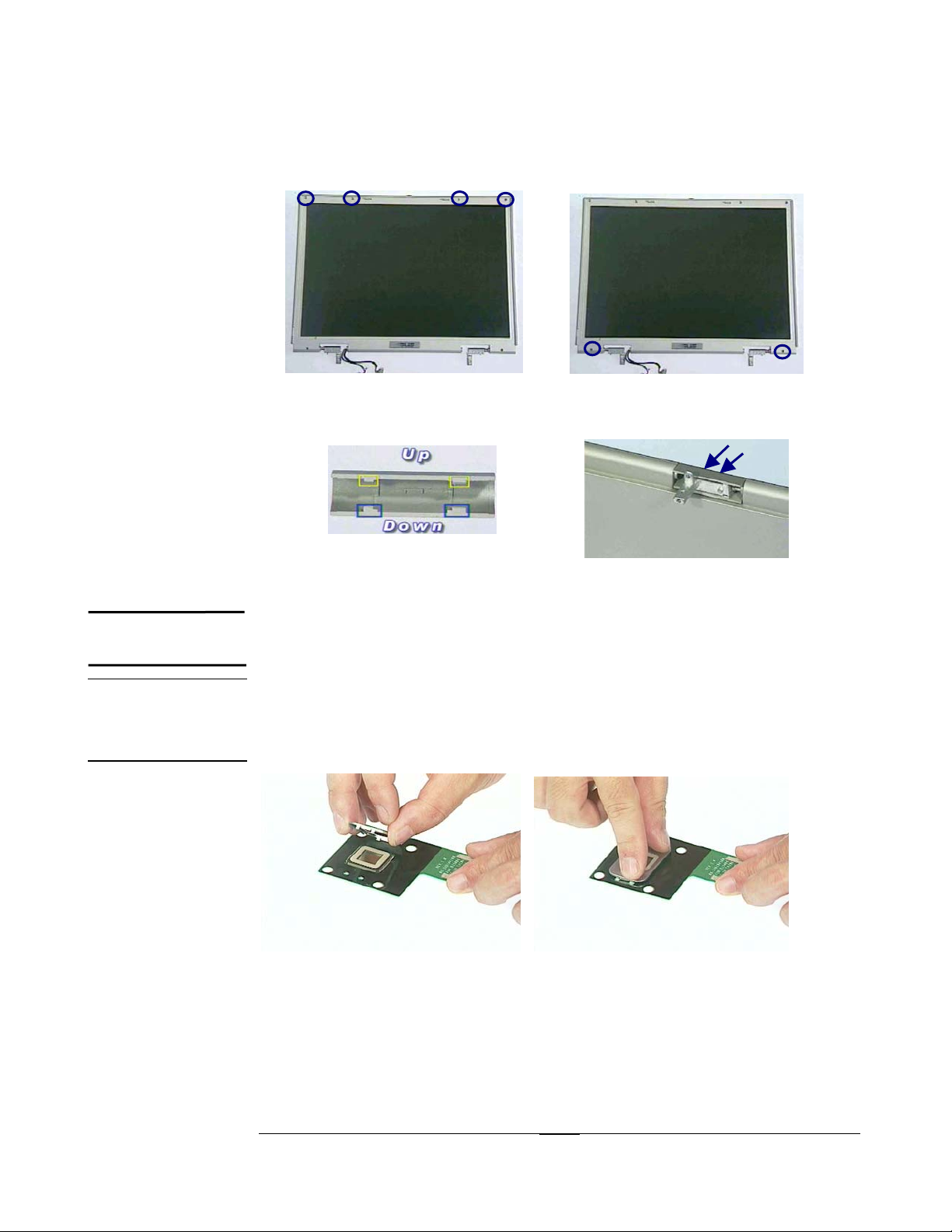
14.Screw 4 screws and place 4 pieces of Rubbers.
15.Screw 2 screws and place 2 pieces of Mylar pads.
16.Lock a set of the Hinge Cover, and notice the direction of the latches.
Top Module Assembly
The illustrations below show how to assemble the Top module.
Fingerprint Board Assembly
1. Place the shielding into the Fingerprint board and fix it.
4 - 4
Page 5
ASSEMBLY PROCEDURE
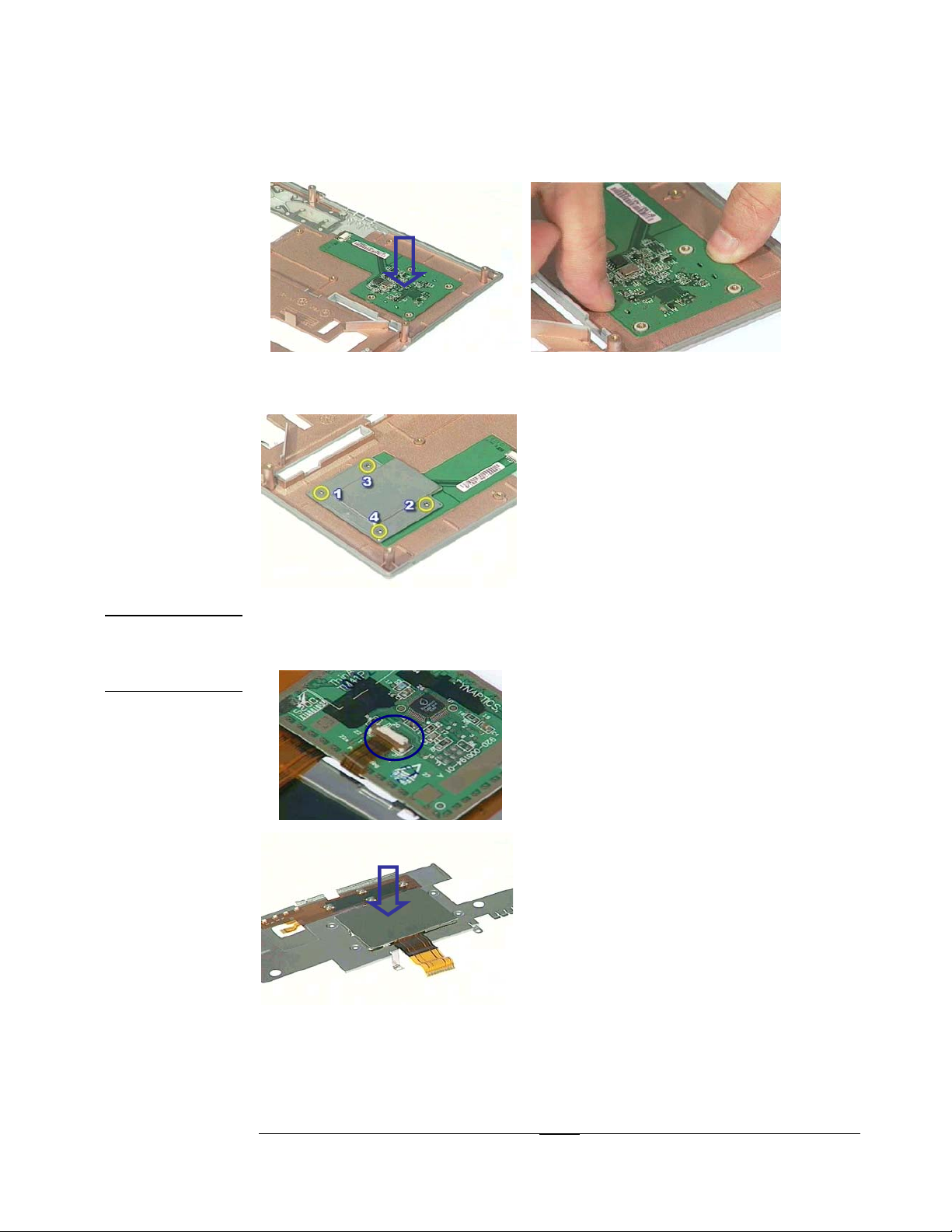
2.Place Fingerprint board in the Top case and fix it here.
TOUCHPAD
MODULE
ASSEMBLY
3.Place the bracket on the fingerprint board and screw 4 screws here.
Touchpad module assembly
1.Insert touch pad FPC, and turn down the touch pad.
4 - 5
Page 6
ASSEMBLY PROCEDURE
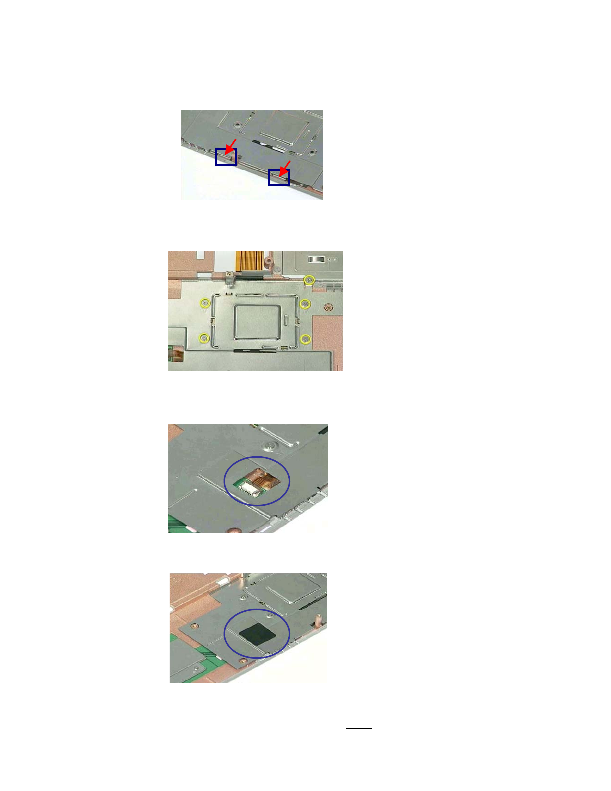
2.Insert the bracket into the case.
3.Insert the Touch pad FPC into the hole of the case.
4.Screw 5 screws (M0*0.5L(K) B-NI, NY)
5.Insert FingerPrint FPC and Fix it here.
6.Stick Mylar label here
4 - 6
Page 7

ASSEMBLY PROCEDURE
5
3
7.Place the Microphone on the hole of the case, and fix the cable .
M/B M O D U L E
A S S E M B L Y
Mainboard module assembly
1.Place PCMCIA socket module, and Screw 4 screws (
NY)
.
SCREW M2*3L(K) B-NI,
2.Place Docking port board, and screw 2 screws (SCREW M2*3L(K) B-NI, NY); Or
place 1394 board, and screw 1 screw(SCREW M2*3L(K) B-NI, NY). (Optional)
3. Place I/O bracket, and screw 6 Spacer screws (No.1~6[SCREW HEX 5mm]).
4 - 7
Page 8

MINI PCI
CARD
ASSEMBLY
ASSEMBLY PROCEDURE
4.Place Docking port bracket, and screw 2 lock screws for Docking Port; or place
the 1394 Bracket, and screw 1 screw (SCREW M2*3L(K) B-NI, NY).
5.Screw 1 screw (SCREW M2*3L(K) B-NI, NY).
Mini PCI Assembly
1.Insert Mini PCI card cables and fix it.
2.Insert Mini PCI card cable into the Mini PCI card (No.1).
3.Insert Mini PCI card into its socket with 45°angle, and push it down to latch it.
4Fix Mini PCI card cable.
1
4 - 8
Page 9

ASSEMBLY PROCEDURE
5
44332
2
1
B O T T O M
M O D U L E
A S S E M B L Y
Bottom module assembly
1.Place the Audio Cover.
2.Insert Main board into the case with45°angle (No.1).
3.Place the speakers (No.2), and screw1 screw (No.3 [M2*6L(B) B-NI, NY]) on
both side.
4.Insert into speaker cables (No.4), and fix speaker cables.
5.Screw 1 screw (No.5 [M2*6L(B) B-NI, NY]).
4 - 9
Page 10

ASSEMBLY PROCEDURE
A S S E M B L E
OF TOP &
BOTTOM MODULE
Assemble of Top and Bottom module
1.First Press inside the PCMCIA door.
2.Place Top module and don’t press the microphone cable.
3.Screw 5 screws (M2*3L(K) B-NI, NY).
4.Screw 12 screws (M2*6L(B) B-NI, NY).
4 - 10
Page 11

ASSEMBLY PROCEDURE
5.Screw 1 screw (M2*3L(K)B-NI, NY).
6.Screw 2 screws (M2*6L(B) B-N, NY).
7.Insert Microphone cable, and Fix it.
8.Use a single-slotted screwdriver to unlock the Touch Pad FPC connector on both
ends (no.1).
Insert the keyboard FPC (no. 2) with a pair of tweezers.
Lock the connector (no. 3).
1. Unlock
2. Cable in
1. Unlock
3. Lock
3. Lock
4 - 11
Page 12

ASSEMBLY PROCEDURE
2
31 4
A S S E M B L E
O F T O P &
L C D M O D U L E
Combining Top case and LCD module
1. Insert LCD module into top module.
2.Screw 2 screws (No.5 [M2.5*6L(K) B-NI, NY]).
3.Screw 4 screws (No.6 [M2.5*6L(K)B-NI, NY]).
4.Screw 2 screws (No.4 [M2.5*6L(K) B-NI, NY]).
5.Insert the LCD coaxial cable (No.1).
6.Insert the Inverter cable, and fix the cables (No.2).
2
1
4 - 12
Page 13

CPU
A
A
INSTALL
ASSEMBLY PROCEDURE
7.Insert the Icon cable here
Installing CPU
The illustrations below show how to remove the CPU module.
1.Use a Vacuum Handling tool to place CPU, and do’t touch the care of CPU
2.Turn the non-removable screw here (no.1) 180 degrees clockwise until B is in
c“L”osed region A to secure the CPU.
New CPU Socket Design
OPEN
CLOSE
B
1
3.Insert Fan cable and fix it.
4 - 13
Page 14

I C O N M O D U L E
D I S A S S E M B L Y
K/B INSTALL
K/B FPC
INSTALL
K/B
PLACEMENT
ASSEMBLY PROCEDURE
4.Place the CPU thermal module.
5.Lock 4 screws (No.1), and screw 2 screws (No.2) .
6.Don’t forget to Stick on new warranty label here.
1
2
ICON Module Disassembly
The steps including two modules of the notebook are Icon Module and Keyboard.
Installing Keyboard
Installing Keyboard FPC
1..Use a single-slotted screwdriver to unlock the FPC connector on both ends (No.1).
2.Insert the keyboard FPC (No. 2) with a pair of tweezers.
3.Lock the connector (No. 3).
2. Cable in
1. Unlock
1. Unlock
3. Lock
3. Lock
Placing Keyboard
Place keyboard and Secure 1 screw (M2*18L(K) B-NI, NY) on the bottom of the
notebook.
4 - 14
Page 15

ASSEMBLY PROCEDURE
ICON
MODULE
PLACEMENT
Placing ICON Module
1.Place the switch board and screw 5 screws (M2*3L(K) B-NI,
NY).
2connect Icon cable to Icon module.
3.Place the Icon module and push it to the left side.
4.Screw 1 screw (No.1 [M2*3L(K) B-NI, NY]) and place mylar pad (No.2).
1
2
4 - 15
Page 16

ASSEMBLY PROCEDURE
2
1
R E M O V A B L E
M O D U L E S
MEMORY
INSTALL
HDD
INSTALL
Removable modules
The illustration below shows how to install the removable modules such as battery,
HDD, FDD, and CD-ROM drive/CD-RW/DVD.
Installing Memory
1.Insert memory into memory socket at the angle of 45 degrees (No.1) and press down
until it clicks into the latches (No. 2).
1
2
45∘
2
2.Insert the cover and fix it.
3.Screw 2 screws (M2*3L(K) B-NI, NY).
Installing HDD
1.Slide the hard drive in the compartment (No.1).
2.Secure 2 screws (No.2 [M3*4L(K) W-NI, NY]).
4 - 16
Page 17

CD-ROM/CDRW/
DVD/FDD
INSTALL
BATTERY
INSTALL
ASSEMBLY PROCEDURE
3.Insert the cover and fix it.
4.Screw 2 screws (No.1 [M2*3L(K) B-NI, NY]).
5.Screw 1 screw (No.2 [M2*6L(B) B-NI, NY]).
1
2
Installing CD-ROM/FDD drive module
1.Slide the module bay in the compartment.
2.Slide the CD-ROM/DVD/CD-RW/FDD in module bay .
Installing battery
Slide the battery pack in the compartment.
4 - 17
 Loading...