

Page 1

®
A7N8X
Series
User Manual
Motherboard
Page 2

Checklist
Product Name: A7N8X
Manual Revision: Revised Edition V4 E1292
Release Date: April 2003
Copyright © 2003 ASUSTeK COMPUTER INC. All Rights Reserved.
No part of this manual, including the products and software described in it, may be reproduced,
transmitted, transcribed, stored in a retrieval system, or translated into any language in any
form or by any means, except documentation kept by the purchaser for backup purposes,
without the express written permission of ASUSTeK COMPUTER INC. (“ASUS”).
Product warranty or service will not be extended if: (1) the product is repaired, modified or
altered, unless such repair, modification of alteration is authorized in writing by ASUS; or (2)
the serial number of the product is defaced or missing.
Products and corporate names appearing in this manual may or may not be registered
trademarks or copyrights of their respective companies, and are used only for identification
or explanation and to the owners’ benefit, without intent to infringe.
The product name and revision number are both printed on the product itself. Manual revisions
are released for each product design represented by the digit before and after the period of
the manual revision number. Manual updates are represented by the third digit in the manual
revision number.
For previous or updated manuals, BIOS, drivers, or product release information, contact
ASUS at: http://www.asus.com or through any of the means indicated on the following page.
ASUS PROVIDES THIS MANUAL “AS IS” WITHOUT WARRANTY OF ANY KIND, EITHER EXPRESS
OR IMPLIED, INCLUDING BUT NOT LIMITED TO THE IMPLIED WARRANTIES OR CONDITIONS OF
MERCHANTABILITY OR FITNESS FOR A PARTICULAR PURPOSE. IN NO EVENT SHALL ASUS, ITS
DIRECTORS, OFFICERS, EMPLOYEES OR AGENTS BE LIABLE FOR ANY INDIRECT, SPECIAL,
INCIDENTAL, OR CONSEQUENTIAL DAMAGES (INCLUDING DAMAGES FOR LOSS OF PROFITS,
LOSS OF BUSINESS, LOSS OF USE OR DATA, INTERRUPTION OF BUSINESS AND THE LIKE),
EVEN IF ASUS HAS BEEN ADVISED OF THE POSSIBILITY OF SUCH DAMAGES ARISING FROM
ANY DEFECT OR ERROR IN THIS MANUAL OR PRODUCT.
SPECIFICATIONS AND INFORMATION CONTAINED IN THIS MANUAL ARE FURNISHED FOR
INFORMATIONAL USE ONLY, AND ARE SUBJECT TO CHANGE AT ANY TIME WITHOUT NOTICE,
AND SHOULD NOT BE CONSTRUED AS A COMMITMENT BY ASUS. ASUS ASSUMES NO
RESPONSIBILITY OR LIABILITY FOR ANY ERRORS OR INACCURACIES THAT MAY APPEAR IN
THIS MANUAL, INCLUDING THE PRODUCTS AND SOFTWARE DESCRIBED IN IT.
ii
Page 3
About this guide
This user manual contains complete information for installing the ASUS
A7N8X Deluxe motherboard.
How this guide is organized
• Chapter 1: Product introduction. A summary of product features and
special attributes of new technologies.
• Chapter 2: Hardware information. A list of hardware setup procedures
and descriptions of all jumpers and connectors on the motherboard.
• Chapter 3: Powering up. Describes the power up sequence with
information on BIOS beep codes.
• Chapter 4: BIOS setup. How to change system settings using onboard
BIOS firmware. Detailed descriptions of the BIOS parameters are supplied.
• Chapter 5: Software support. A summary of contents on the
motherboard support CD ROM.
• Appendix and Glossary . Optional components and technical definitions.
• Index
Conventions used in this guide
Features
T o make sure that you perform set-up tasks properly , take note of the following
symbols used throughout this manual.
WARNING! Information to prevent injury to yourself.
CAUTION! Information to prevent damage to the components.
IMPORTANT! Information that you MUST follow to complete a task.
NOTE! Tips and helpful information.
References
1. NVIDIA nForce Audio Panel Manual
2. Silicon Image Sil 3112 SATALink Controller Driver Installation
3. SATARAID Software User’s Manual
iii
Page 4

Safeguards
Contents
About this guide ..........................................................................................iii
How this guide is organized...............................................................iii
Conventions used in this guide..........................................................iii
Safety information ...................................................................................... vi
FCC/CDC statements.................................................................................vii
ASUS contact information ......................................................................... viii
A7N8X Specifications summary ................................................................. ix
Chapter 1: Product introduction ............................................. 1
Welcome! .................................................................................................... 1
1.1 Package contents.............................................................................. 1
1.2 Core Specifications ........................................................................... 2
1.3 ASUS Special Features..................................................................... 3
1.4 Motherboard Components................................................................. 4
1.5 Special Features ............................................................................... 6
Chapter 2: Hardware information ............................................ 7
2.1 Motherboard installation .................................................................... 7
2.2 Layout contents ................................................................................. 9
2.3 Before you proceed ......................................................................... 10
2.4 Central Processing Unit (CPU) ........................................................ 11
2.5 System memory .............................................................................. 13
2.6 Expansion slots ............................................................................... 15
2.7 Jumpers .......................................................................................... 19
2.8 Connectors...................................................................................... 22
Chapter 3: Powering up ......................................................... 35
3.1 Starting up for the first time.............................................................. 35
3.2 Vocal POST Messages ................................................................... 36
3.3 Powering-off the computer .............................................................. 38
Chapter 4: BIOS ..................................................................... 39
iv
4.1 Managing and updating your BIOS.................................................. 39
4.2 BIOS Setup program ....................................................................... 42
4.3 Main Menu ...................................................................................... 46
4.4 Advanced Menu .............................................................................. 51
Page 5

Contents
4.4.1 Advanced BIOS Features.................................................. 51
4.4.2 Advanced Chipset Features .............................................. 55
4.4.3 Integrated Peripherals ....................................................... 58
4.4.4 Power Management Setup ................................................ 61
4.4.5 PnP / PCI Configurations................................................... 63
4.5 Security Menu ................................................................................. 65
4.6 Hardware Monitor Menu .................................................................. 66
4.7 Exit Menu ....................................................................................... 68
Chapter 5: Software support ................................................. 71
5.1 Install an operating system .............................................................. 71
5.2 Support CD information ................................................................... 71
5.3 A7N8X Motherboard Support CD .................................................... 72
5.3.1 Installation Procedure........................................................ 72
5.3.2 Installation of PCI Drivers: Win98 ...................................... 73
5.4 ASUS PC Probe.............................................................................. 75
5.5 ASUS Live Update .......................................................................... 80
5.6 3Deep Color Tuner.......................................................................... 81
5.7 NVIDIA nForce Control Panel .......................................................... 83
5.8 Winbond Editor................................................................................ 88
5.9 RAID 0/1 Configurations.................................................................. 91
Chapter 6: Appendix .............................................................. 95
6.1 Glossary.......................................................................................... 95
Index ........................................................................................ 99
v
Page 6

Safety information
Electrical safety
• To prevent electrical shock hazard, disconnect the power cable from the
electrical outlet before relocating the system.
• When adding or removing devices to or from the system, ensure that the
power cables for the devices are unplugged before the signal cables are
connected. Disconnect all power cables from the existing system before
you add a device.
• Before connecting or removing signal cables from the motherboard, ensure
that all power cables are unplugged.
• Seek professional assistance before using an adpater or extension cord.
These devices could interrupt the grounding circuit.
• Make sure that your power supply is set to the voltage available in your
area.
• If the power supply is broken, contact a qualified service technician or your
retailer .
Operational safety
• Before installing the motherboard and adding new devices, carefully read
all the manuals that came with the package.
• Before use ensure all cables are correctly connected and the power cables
are not damaged. If you detect any damage, contact the dealer immediately .
• To avoid short circuits, keep paper clips, screws, and staples away from
connectors, slots, sockets and circuitry.
• Avoid dust, humidity, and temperature extremes. Do not place the product
in any area where it may become wet.
• Mount the motherboard inside a standard PC enclosure.
• If you encounter technical problems with the product, contact a qualified
service technician or the dealer.
vi
Page 7

FCC/CDC statements
Federal Communications Commission Statement
This device complies with FCC Rules Part 15. Operation is subject to the
following two conditions:
• This device may not cause harmful interference, and
• This device must accept any interference received including interference
that may cause undesired operation.
This equipment has been tested and found to comply with the limits for a
Class B digital device, pursuant to Part 15 of the FCC Rules. These limits
are designed to provide reasonable protection against harmful interference
in a residential installation. This equipment generates, uses and can radiate
radio frequency energy and, if not installed and used in accordance with
manufacturer’s instructions, may cause harmful interference to radio
communications. However, there is no guarantee that interference will not
occur in a particular installation. If this equipment does cause harmful
interference to radio or television reception, which can be determined by
turning the equipment off and on, the user is encouraged to try to correct the
interference by one or more of the following measures:
• Reorient or relocate the receiving antenna.
• Increase the separation between the equipment and receiver.
• Connect the equipment to an outlet on a circuit different from that to
which the receiver is connected.
• Consult the dealer or an experienced radio/TV technician for help.
The use of shielded cables for connection of the monitor to the
graphics card is required to assure compliance with FCC regulations.
Changes or modifications to this unit not expressly approved by the
party responsible for compliance could void the user’s authority to
operate this equipment.
Canadian Department of Communications Statement
This digital apparatus does not exceed the Class B limits for radio noise
emissions from digital apparatus set out in the Radio Interference
Regulations of the Canadian Department of Communications.
This class B digital apparatus complies with Canadian ICES-003.
vii
Page 8

ASUS contact information
ASUSTeK COMPUTER INC. (Asia-Pacific)
Address: 150 Li-T e Road, Peitou, Taipei, T aiwan 1 12
General T el: +886-2-2894-3447
General Fax: +886-2-2894-3449
General Email: info@asus.com.tw
Technical Support
MB/Others (T el): +886-2-2890-7121 (English)
Notebook (T el): +886-2-2890-7122 (English)
Desktop/Server (Tel): +886-2-2890-7123 (English)
Support Fax: +886-2-2890-7698
Web Site: www.asus.com.tw
ASUS COMPUTER INTERNATIONAL (America)
Address: 44370 Nobel Drive, Fremont, CA 94538, USA
General Fax: +1-510-608-4555
General Email: tmd1@asus.com
Technical Support
Support Fax: +1-510-608-4555
General Support: +1-510-739-3777
Web Site: www.asus.com
Support Email: tsd@asus.com
ASUS COMPUTER GmbH (Germany & Austria)
Address: Harkortstr . 25, 40880 Ratingen, BRD, Germany
General Fax: +49-2102-442066
General Email: sales@asuscom.de (for marketing requests only)
Technical Support
Support Hotline: MB/Others: +49-2102-9599-0
Notebook (T el): +49-2102-9599-10
Support Fax: +49-2102-9599-1 1
Support (Email): www .asuscom.de/de/support (for online support)
Web Site: www .asuscom.de
viii
Page 9

A7N8X specifications summary
CPU
Chipset
Front Side Bus (FSB)
Memory
Expansion slots
IDE
Serial A TA (optional)
Audio (optional)
Socket A for AMD Duron™/Athlon™/Athlon™XP 3000+ or
higher
400*/333 MHz FSB Support (*PCB 2.0 or later versions)
®
Northbridge: NVIDIA
Southbridge: NVIDIA® nForce2 MCP-T (Deluxe Model)/MCP
400*/333/266/200Mhz (*PCB 2.0 or later versions)
3 x 184-pin DDR DIMM Sockets
Max. 3 GB unbuffered PC3200/2700/2100/1600 non-ECC
DDR RAM memory. Dual-Channel DDR400 support.
(Visit ASUS website for latest qualified DDR400 module list.)
5 x PCI
1 x AGP Pro/8X (1.5V only)
2 x UltraDMA 133/100/66/33
Silicon Image Sil 3112A Controller with 2 Ports
(Supports RAID 0/1) (Deluxe model only)
Realtek ALC650 6CH with built-in HP amplifier
Integrated APU (Audio Processor Unit) (Deluxe model only)
SoundStorm™/Dolby® Digital (AC-3) Encoder
(Deluxe model only)
nForce2 SPP (Ultra 400)
LAN (optional)
1394 (optional)
Special Features
Back Panel I/O Ports
2 Ports
MCP integrated NVIDIA MAC + Realtek 8201BL PHY
MCP integrated 3Com MAC + BroadCom AC101L PHY
(Deluxe model only)
2 Ports MCP-T integrated IEEE 1394a + Realtek PHY
8801B (Deluxe model only)
ASUS Q-Fan Technology
ASUS POST Reporter (Deluxe model only)
ASUS C.O.P. (CPU Overheating Protection)
Power Loss Restart
CPU Throttle
Support S/PDIF in/out (optional)
1 x Parallel
1 x Serial
1 x PS/2 Keyboard
1 x PS/2 Mouse
1 x S/PDIF out + 1 x Surround L/R audio jack + 1 x CNTR/
LFE audio jack (Deluxe model only)
1 x Audio I/O
2 x RJ-45 Port (3COM RJ-45 port - Deluxe model only)
4 x USB 2.0
(continued on the next page)
ix
Page 10

A7N8X specifications summary
Internal I/O
Connectors
BIOS features
Industry standard
Manageability
Support CD contents
1 x USB 2.0 connector supports additional 2 USB 2.0 ports
(optional)
Game connector
CPU/Power/Chassis FAN connectors
20-pin ATX Power connector
IDE LED connector, Power LED connector
2 x SATA connector (Deluxe model only)
2 x 1394 connector (Deluxe model only)
WOR, WOL, Chassis Intrusion, SM Bus, SIR
Headphone (optional)
Front MIC (optional)
CD / AUX / Modem audio in
Front Panel Audio connector (optional)
4Mb Flash ROM, Award BIOS, TCAV, PnP, DMI2.0, DMI,
Green
PCI 2.2, USB 1.1/2.0.
DMI 2.0, WOL, WOR, Chassis Intrusion, SM Bus
Device drivers
ASUS PC Probe
Trend Micro
ASUS LiveUpdate Utility
tm
PC-cillin 2002 anti-virus software
Accessories
Form Factor
* Specifications are subject to change without notice.
InterVideo WinCinema (optional)
User’s manual
Support CD
SATA cable (Deluxe model only)
2-port 1394 Bracket (Deluxe model only)
1 x UltraDMA 33 cable
1 x UltraDMA 133/100/66 cable
FDD cable
9-pin COM cable
2-port USB/Game port bracket (Deluxe model only)
I/O shield
ATX form factor: 12 in x 9.6 in
x
Page 11
Chapter 1
Product introduction
Page 12

ASUS A7N8X motherboard
Page 13

Welcome!
Thank you for buying the ASUS® A7N8X motherboard!
The A7N8X is powered by AMD
and supplies advanced features to ensure long-lasting, superlative
performance. The ASUS® A7N8X motherboard is the prime choice for home
PCs and workstations.
~ Up to 3 GB of DDR RAM
~ New ultra-compact Serial ATA IDE connectors. (optional)
~ High-resolution graphics via an AGP 8X slot
~ Digital Audio Interface for 3D sound
~ Onboard LAN PHY for instant networking (optional)
~ Four USB ports plus one header for two more
~ UltraDMA133 data rates
The A7N8X is the perfect vehicle to get ahead in the world of power computing!
®
Athlon™, Athlon™ XP and Duron™ processors
1.1 Package contents
Check your A7N8X package for the following items.
ASUS A7N8X motherboard (ATX form factor: 12 in x 9.6 in)
ASUS A7N8X support CD
ASUS 2-port USB / Game port module (optional)
40-pin 80 conductor UltraDMA133/100/66/33 IDE ribbon cable
Ribbon cable for a 3.5-inch floppy drive
COM 2 bracket
I/O shield
Bag of extra jumper caps
User Guide
2 pcs. Serial ATA Cable (optional)
2 pcs. ASUS IEEE 1394 2-port bracket (optional)
2 pcs. ASUS IEEE 1394 cable (optional)
If any of the above items is damaged or missing, contact your retailer.
ASUS A7N8X motherboard user guide
1
Page 14

1.2
Core Specifications
The A7N8X motherboard is designed and assembled according to the highest
standards. This ASUS motherboard represents the latest advances and
offers users the finest componentry available today...
®
AMD
North Bridge Chipset: the nVidia
Athlon™/ Athlon™ XP and Duron™ Socket A (462) Processor
®
nForce2™ SPP (Ultra 400) North Bridge
controller chipset. The controller supports a 64/128bit DDR memory
controller and up to 3 GB of 400/333/266/200MHz DDR memory. The
128bit memory controller provides a exceptional 6.4 GB/second system
memory bandwidth.
®
South Bridge Chipset: Features the brand new nV idia
nForce2™ MCP-T/
MCP integrated peripheral South Bridge controller operates at 800MB/
sec to communicate with the North Bridge for maximum bandwith required
for PCI, USB and support for Fast Ethernet devices. The chipset has an
™
integrated APU (Audio Processing Unit) for Dolby
digital
encoding(optional). The controller supports standard UltraDMA133/100/
66/33 for burst mode data transfer rates of up to 133MB/sec. Separate
data paths for each IDE channel are built-in for up to two IDE devices.
The controller supports 2 IEEE 1394 ports (optional), six USB ports, two
LAN ports (optional), and is PCI rev2.2 compliant. The MCP-T/MCP
supplies an LPC 1.0 interface along with AT legacy functions, a clock
synthesizer and meets ACPI 1.0 and PCI Power Management 1.1
specifications.
PC3200 / PC2700 DDR Support: Equipped with three Double Data Rate
Dual Inline Memory Module (DDR DIMM) sockets to support up to 3GB of
DDR DRAM, the newest memory standard with the highest bandwidth
and lowest latency currently available. This new memory technology
supplies data transfer rates up to 6.4 GB/s for 400MHz DDR SDRAM
and 5.4GB/s for 333MHz DDR SDRAM.
UltraDMA133/100 Support: Comes with an onboard PCI Bus Master IDE
controller with two connectors that support four IDE devices on two
channels. Supports UltraDMA133/100/66/33, PIO Modes 3 & 4, Bus
Master IDE DMA Mode 2, and Enhanced IDE devices, such as DVDROM, CD-ROM, CD-R/RW, LS-120, and Tape Backup drives.
Multi-I/O Chipset: ITE IT8708 offers support for a variety of I/O functions.
Provides two high-speed UART compatible serial ports and one parallel
port with EPP and ECP capabilities. UART2 can also be directed from
COM2 to the Infrared Module for wireless connections. The Super I/O
controller supports a floppy disk drive, PS/2 keyboard, and PS/2 mouse.
2
Chapter 1: Product introduction
Page 15

Connections: Parallel Port, PS/2 mouse Port, PS/2 keyboard, four USB
ports, two LAN ports (optional), Surround L/R audio jack(optional), CNTR/
LFE audio jack(optional), COM port, Microphone, Line In Jack, Line Out
Jack, S/PDIF_OUT (optional), ATX power.
Expansion: One AGP Pro 8X, a USB header , two serial A TA IDE connectors
(optional), two 1394 connectors (optional), COM port header, five PCI
slots, S/PDIF digital audio connector (optional), front audio panel
connector, game port header.
1.3 ASUS Special Features
ASUS POST Reporter™ (optional)
A7N8X offers the ASUS POST Reporter™ to provide friendly voice
messages and alerts during the Power-On Self-Test (POST). Through
an added external speaker, messages inform you of system boot
™
status and causes of boot errors. Bundled Winbond
software helpsa you customize voice messages, and offers multilanguage support.
Voice Editor
ASUS Q-Fan Technology
The ASUS Q-Fan technology smartly adjusts the fan speeds according
to the system loading to ensure quiet, cool, and efficient operation.
C.O.P. (CPU Overheating Protection):
With AMD
®
Athlon XP™ installed, the motherboard offers automatic CPU
Overheating Protection to prolong the life of the entire system. If the CPU
temperature exceeds the set criteria, the PC shuts down automatically.
ASUS A7N8X motherboard user guide
3
Page 16

1.4
Motherboard Components
Multi-I/O controller 9Multi-I/O controller 9Multi-I/O controller 9Multi-I/O controller 9Multi-I/O controller 9Multi-I/O controller 9Multi-I/O controller 9Multi-I/O controller 9Multi-I/O controller 9Multi-I/O controller 9Multi-I/O controller 9Multi-I/O controller 9Multi-I/O controller 9Multi-I/O controller 9Multi-I/O controller 9Multi-I/O controller 9Multi-I/O controller 9Multi-I/O controller 9Multi-I/O controller 9Multi-I/O controller 9Multi-I/O controller 9Multi-I/O controller 9Multi-I/O controller 9Multi-I/O controller 9Multi-I/O controller 9Multi-I/O controller 9Multi-I/O controller 9Multi-I/O controller 9Multi-I/O controller 9Multi-I/O controller 9Multi-I/O controller 9Multi-I/O controller 9Multi-I/O controller 9Multi-I/O controller 9Multi-I/O controller 9Multi-I/O controller 9Multi-I/O controller 9Multi-I/O controller 9Multi-I/O controller 9Multi-I/O controller 9Multi-I/O controller 9Multi-I/O controller 9Multi-I/O controller 9Multi-I/O controller 9Multi-I/O controller 9Multi-I/O controller 9Multi-I/O controller 9Multi-I/O controller 9Multi-I/O controller 9Multi-I/O controller 9Multi-I/O controller 9Multi-I/O controller 9Multi-I/O controller 9Multi-I/O controller 9Multi-I/O controller 9Multi-I/O controller 9Multi-I/O controller 9Multi-I/O controller 9Multi-I/O controller 9Multi-I/O controller 9Multi-I/O controller 9Multi-I/O controller 9
Before installing the A7N8X motherboard, take time to familiarize yourself
with its configuration:
Processor Support Socket A for AMD
Chipsets nVidia
4Mbit Programmable Flash EEPROM (see page 6)........ 7
nVidia
Multi-I/O controller ........................................................... 9
Serial A T A Controller ...................................................... 18
1394 PHY Realtek 8801B .............................................. 22
Main Memory Maximum 3GB support
3 DDR DIMM Sockets...................................................... 3
Expansion Slots 5 PCI Slots..................................................................... 20
1 Accelerated Graphics Port (AGP) Pro Slot ................. 31
System I/O 1 Floppy Disk Drive Connector ........................................ 5
2 IDE Connectors (UltraDMA133/100/66 Support).......... 6
1 COM2 Header............................................................. 10
1 Gameport Connector ...................................................11
1 Infrared Connector...................................................... 12
1 Panel Connector ......................................................... 13
1 SM Bus Connector...................................................... 14
USB Headers (Ports 5/6) ............................................... 15
Serial A T A Headers ........................................................ 17
Modem Connector ......................................................... 21
IEEE 1394 Headers ....................................................... 23
S/PDIF Connector.......................................................... 24
1 PS/2 Mouse Connector.................................. (green) 32
1 PS/2 Keyboard Connector ............................ (purple) 45
RJ45 Connector (3COM LAN Controller) ...................... 33
RJ45 Connector (NVIDIA LAN Controller) ..................... 35
1 Parallel Port ................................................................ 34
USB Connectors (Ports 3/4) .......................................... 44
USB Connectors (Ports 1/2) .......................................... 39
1 Serial Ports (COM1) ................................................... 43
Hardware Monitoring System Voltage Monitor (integrated in ASUS ASIC)...... 16
Special Feature Onboard LED (Green) ................................................... 19
Onboard AGP Warning LED (Red) ................................ 29
Network Feature Realtek 8201BL PHY .................................................... 28
BroadCom PHY ............................................................ 30
3Com LAN ..................................................................... 33
NVIDIA LAN ................................................................... 35
Audio Features Audio Codec .................................................................. 25
CD / AUX Audio Connectors .......................................... 26
Front Panel Audio Connectors....................................... 27
1 Line In Connector .................................... (light blue) 36
1 Line Out Connector........................................... (lime) 37
1 Microphone Connector .....................................(pink) 38
1 S/PDIF out Connector................................... (yellow) 40
1 Surround L/R audio Connector .......................(violet) 41
1 CNTR / LFE Connector................................ (orange) 42
Power ATX Power Supply Connector ......................................... 4
Form Factor ATX
®
nForce2™ SPP (Ultra 400) North Bridge.............. 2
®
nForce2™ MCP-T/MCP South Bridge.................. 8
®
Athlon™ and Duron™ Processors ....... 1
Location
4
Chapter 1: Product introduction
Page 17
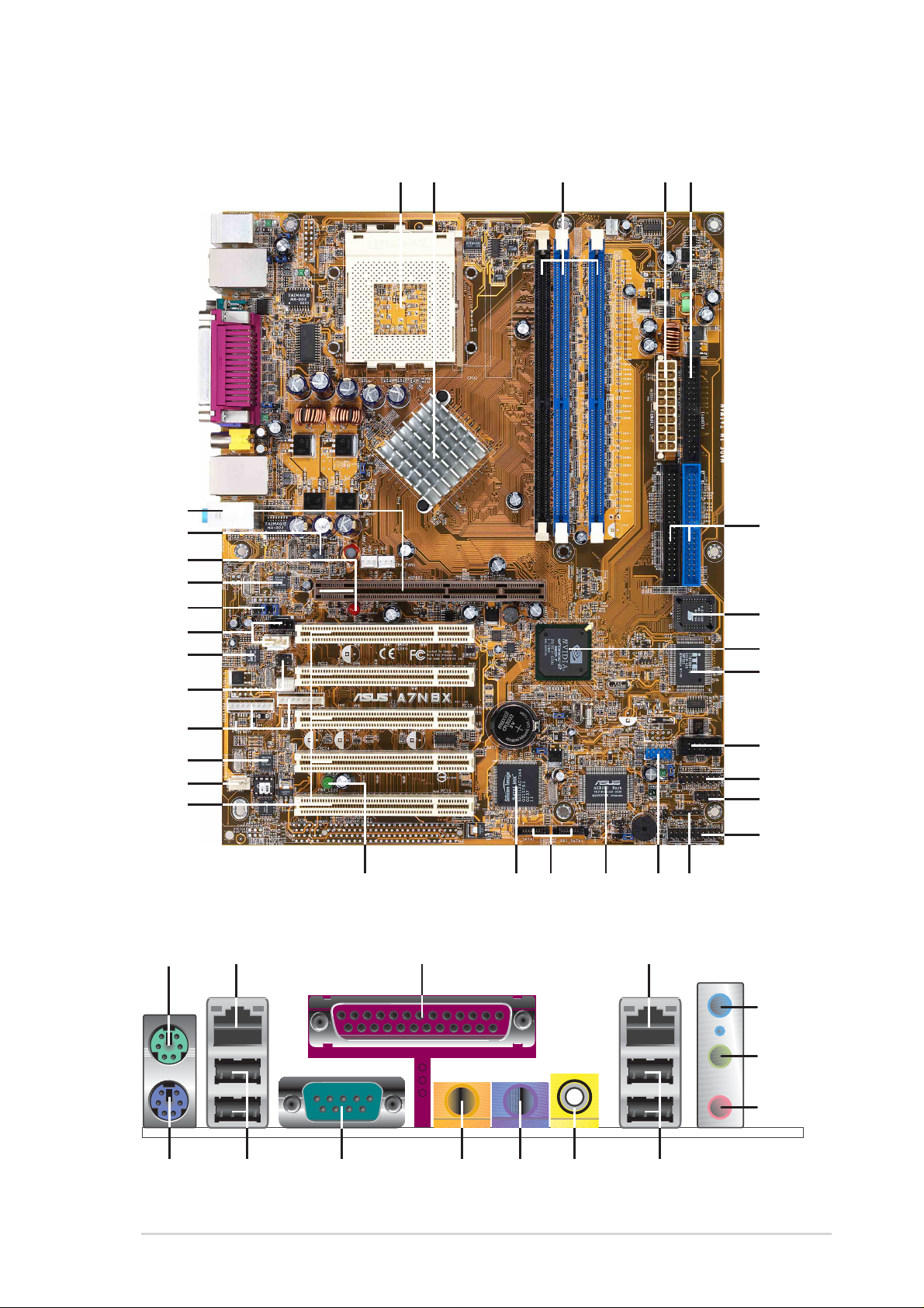
1.4.1 Component Locations
2351
4
0
1
2
3
32 34
33
35
31
30
29
28
27
26
25
24
23
22
21
20
6
19
18
16
7
8
9
1
1
1
1
141517
45 43
ASUS A7N8X motherboard user guide
44
42 41 40
36
37
38
39
5
Page 18

1.4.1 Component Locations (cont’)
CAUTION!
• This motherboard uses the A7N8X Deluxe BIOS file for 4Mb flash
ROM. Another series model A7N8X uses the BIOS file for a 2Mb
flash ROM. Make sure to use the correct BIOS file on each model.
• PCB 2.0 BIOS version or later are not compatible with PCB 1.06 or
earlier BIOS versions.
NOTE!
• The A7N8X series motherboard support Front Side Bus (FSB) 400
starting from PCB version 2.0 or later.
• The PCB (Printed Circuit Board) version is located beside the
motherboard name printed on the motherboard.
1.5 Special Features
Serial ATA: Silicon Image supplies the Sil-3112A chipset, supporting the
ultra-compact 7-pin Serial-ATA IDE device support.
Dual LAN/DualNet: Two south bridge integrated 3COM and Nvidia LAN
controllers supply two separate outputs for the network. (optional)
IEEE 1394: Two header support a multiplicity of connections for IEEE 1394
compatible devices. (optional)
T emperature, Fan and V oltage Monitoring: CPU temperature is monitored
by ASUS ASIC through a thermal sensor mounted under the CPU. The
sensor signals the computer to prevent overheating and damage. The
CPU and system fans can be monitored for RPM and failure. System
voltage levels are monitored to ensure stable current to critical
motherboard components.
ACPI Ready: Advanced Configuration Power Interface (ACPI) provides more
Energy Saving Features for operating systems that support OS Direct
Power Management (OSPM).
Concurrent PCI: Concurrent PCI allows multiple PCI transfers from PCI
master busses to the memory and processor.
Auto Fan Off: The system fans powers off automatically even in sleep mode.
Dual Function Power Button: Push the power button for less than 4 seconds
when the system is operating places the system into sleep or soft-off
modes; press the power button for more than 4 seconds, and the system
enters the soft-off mode regardless of the BIOS setting.
Dolby
™
Integrated Audio: MCP-T South bridge integrated Audio Processing
™
Unit (APU) for Dolby
Digital Encoding. (optional)
Dual Channel DDR 400: The 128-bit TwinBank DDR Memory architecture
doubles the DDR400 (PC3200) bandwidth. System bottlenecks are
eliminated and traffic improved with peak bandwidths of up to 6.4 GB/s.
Page 19
Chapter 2
Hardware information
Page 20

ASUS A7N8X motherboard
Page 21
2.1 Motherboard installation
The A7N8X uses the ATX form factor, measuring 24.5 cm
(9.6 in.) x 30.5 cm (12.0 in.) - a standard fit for most large chassis.
WARNING! Unplug the power cord before installing the motherboard.
Failure to do so may cause you physical injury and damage motherboard
components.
2.1.1 Placement direction
When installing the motherboard, take care to orient the chassis correctly:
The edge with external ports goes to the rear part of the chassis. Refer to the
image below. It may be more convenient to install major cables, the CPU
and modular components before fixing the motherboard inside the case frame.
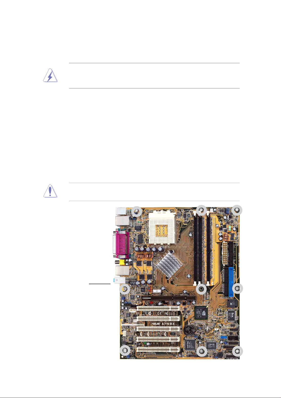
2.1.2 Screw holes
Place nine (9) screws into the holes indicated by circles to secure the
motherboard to the chassis.
CAUTION! Do not overtighten the screws! Doing so may damage the
motherboard.
Place this side towards
the rear of the chassis
ASUS A7N8X motherboard user guide
7
Page 22

24.5cm (9.64in)
®
PS/2
T: Mouse
B: Keyboard
Bottom:
Top:
USB3
RJ-45
USB4
COM1
CNTR/
LFE1
SURR1
SPDIFOUT2
Bottom:
Top:
USB1
RJ-45
USB2
Top:Line In
Center:Line Out
Below:Mic In
PARALLEL PORT
KBPWR1
USBPWR_34
USBPWR_12
CPU_FSB
ACL101L
Socket 462
nVidia
nForce2
SPP
(Ultra400)
Chipset
CPU_FAN1
ATX Power Connector
DDR DIMM1 (64/72 bit, 184-pin module)
DDR DIMM2 (64/72 bit, 184-pin module)
DDR DIMM3 (64/72 bit, 184-pin module)
0 1
2 3
4 5
FLOPPY1
FPAUDIO1
Audio
Codec
IEEE1394_2
MODEM1
AGP_WARN1
PCI 1
PCI 2
PCI 3
PCI 4
PCI 5
CHA_FAN1
A7N8X
CR2032 3V
Lithium Cell
CMOS Power
SATA_EN1
SATALInk
Chipset
SEC_SATA1 PRI_SATA1
nForce2
MCP-T/MCP
Chipset
CLRTC1
with Hardware
ASUS
ASIC
Monitor
PWRTMP1
CHASSIS1
USB56
USBPWR_56
BUZZ1
SEC_IDE1
Super
IR_CON1
IDELED1
CTRL_PANEL1
PRI_IDE1
4Mb
BIOS
I/O
COM2
GAME1
SMB1
Realtek
RTL8201
AUX1
SPDIF1
Realtek
RTL8801
Speech
Controller
PWR_FAN1
Accelerated Graphics Port (AGP Pro)
CD1
IEEE1394_1
PWR_LED1
Optional components are grayed in the above motherboard layout.
30.5cm (12.0in)
8
Chapter 2: Hardware information
Page 23

2.2 Layout contents
CPU, Memory and Expansion Slots
1) Socket 462 p. 11 CPU Support
2) DIMM 1/2/3 p. 13 System Memory Support
3) PCI 1/2/3/4/5 p. 15 32-bit PCI Bus Expansion Slots
4) AGP Pro 8x p. 18 Accelerated Graphics Slot
Motherboard Settings (Jumpers)
1) SATA_EN1 p. 19 Serial ATA Setting (3 pin)
2) KBPWR1 p. 19 Keyboard Wake Up (3 pin)
3) USBPWR12, 34, 56 p. 20 USB Device Wake-up (2x3 pin)
4) CLRTC1 p. 21 Clear RTC/CMOS RAM (3 Pin)
Connectors
1) PS2KBMS p. 22 PS/2 Mouse Port (6 pin female)
2) PS2KBMS p. 22 PS/2 Keyboard Port (6 pin female)
3) USB p. 23 Universal Serial Bus Ports 1 & 2 (2 x 4 pin female)
4) COM2 p. 23 Serial Port and Header (9 pin male, 10-1 pin male)
5) RJ45 p. 24 Fast-Ethernet Port Connector (4 pin) (Optional)
6) PRINTER p. 24 Parallel Port (25 pin female)
7) AUDIO p. 25 Audio Connectors (Six 1/8” jacks)
8) IDELED p. 25 IDE Activity LED (Two 40-1 pin)
9) FLOPPY p. 26 Floppy Disk Drive Connector (34-1 pin)
10) PRIMARY / SEC. IDE p. 26 IDE Connectors (2 x 40-1 pin)
11) PRI/SEC_SAT A1 p. 27
12) IR_CON1 p. 27 ASUS Front Panel Audio Connector (10 pin)
13) CPU_FAN1 p. 28 CPU Fan Connector (3 pin)
14) 1394HEAD p. 28 IEEE-1394 Header (8-pin) (Optional)
15) ATXPWR p. 29 Power Supply Connectors (20 pin block)
16) SMB p. 29 SMBus Connector (6-1 pin)
MODEM, CD_IN1, AUX
17)
18) SPDIF1 p. 30 Digital Audio Interfaces (6 pin) (Optional)
19) USB_56 p. 31 USB Headers (10-1 pin)
20) PWRTMP1 p. 31
21) GAME p. 32 Game Connector (16-1 pin)
p. 30 Internal Audio Connectors (2 x 4 pin ) (Optional)
SATA Serial ATA Connectors (2 x 7-pin)
Power Supply Thermal Sensor (2-pin ) (Optional)
22) CHASSIS1 p. 32 Chassis Open Alarm Lead (4-1 pin)
23) FPAUDIO1 p. 33 Front Panel Audio (10-1 pin)
24) PWR_LED (Panel) p. 33 System Power LED Lead (3-1 pin )
25) KEYLOCK (Panel) p. 33 Keyboard Lock Switch Lead (2 pin )
26) SPEAKER (Panel) p. 33 System Warning Speaker Lead (4 pin )
27) SMI (Panel) p. 34 System Management Interrupt Lead (2 pin)
28) PWR (Panel) p. 34 ATX Power Switch / Soft-Off Switch Lead (2 pin)
29) RESET (Panel) p. 34 Reset Switch Lead (2 pin)
ASUS A7N8X motherboard user guide
9
Page 24
2.3 Before you proceed
®
d
d
Take note of the following precautions before you install motherboard
components or change any motherboard settings.
CAUTION!
1. Unplug the power cord from the wall socket before touching
components.
2. Use a grounded wrist strap or touch a safely grounded object or to a
metal object, such as the power supply case, before handling
components to avoid damaging them due to static electricity.
3. Hold components by the edges and do not to touch the ICs on them.
4. Whenever you uninstall any component, place it on a grounded
antistatic pad or in the bag that came with the component.
5. Before you install or remove any component, ensure that the
A TX power supply is switched off or the power cord is detached
from the power supply . Failure to do so may cause severe damage
to the motherboard, peripherals, and/or components.
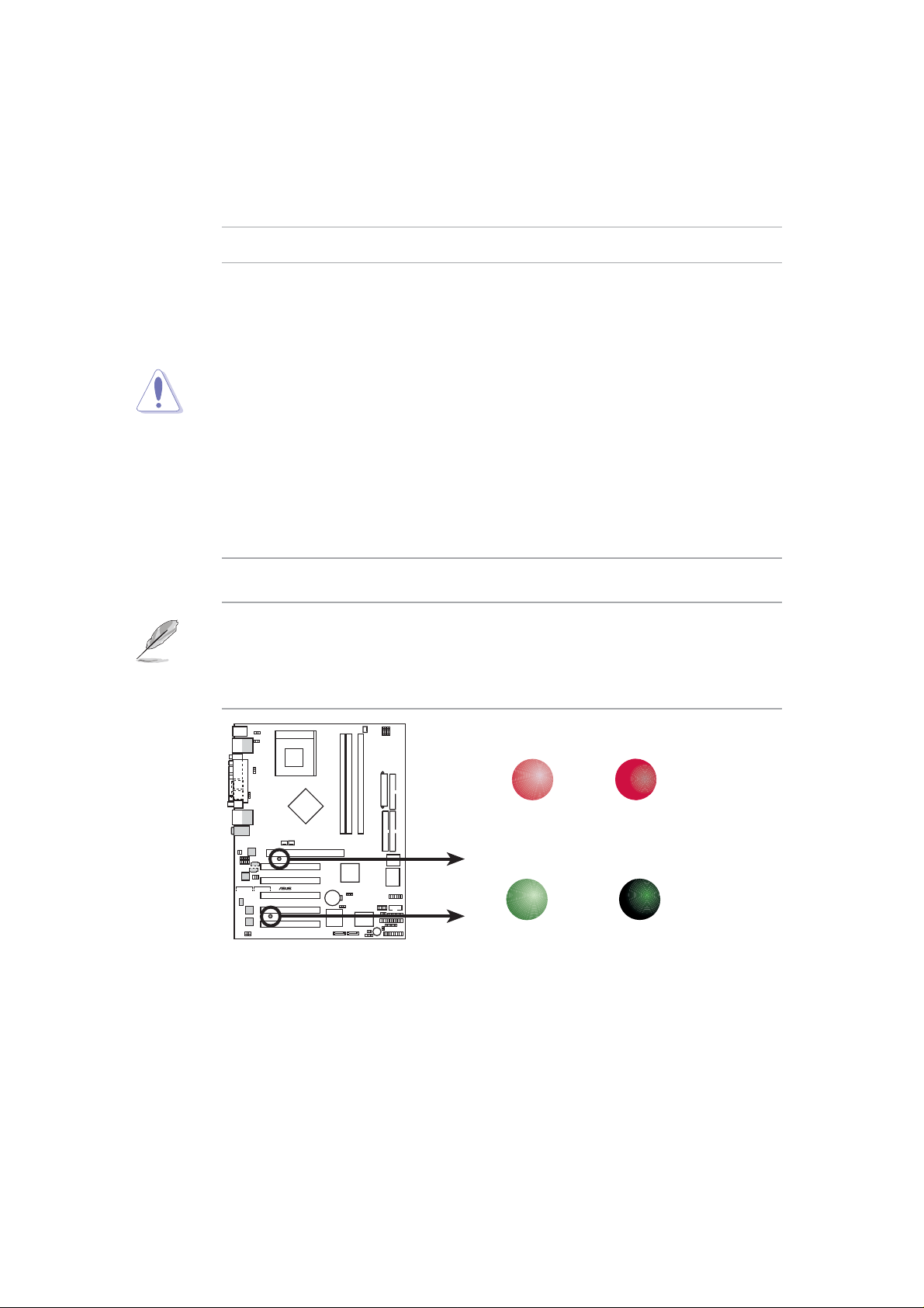
NOTE! When lit, the onboard GREEN LED indicates that the system is
ON, in sleep mode or in soft-off mode, not powered OFF. See the
illustration below. The RED LED warns if the AGP card is incorrectly
installed, or is the wrong type of card for this particular motherboard.
WARNING
A7N8X
A7N8X Onboard LED
ON
Incorrect
AGP Card
PWR_LED
ON
Standby
Power
OFF
Correct
AGP Car
OFF
Powere
Off
10
Chapter 2: Hardware information
Page 25
2.4 Central Processing Unit (CPU)
®
2.4.1 Overview
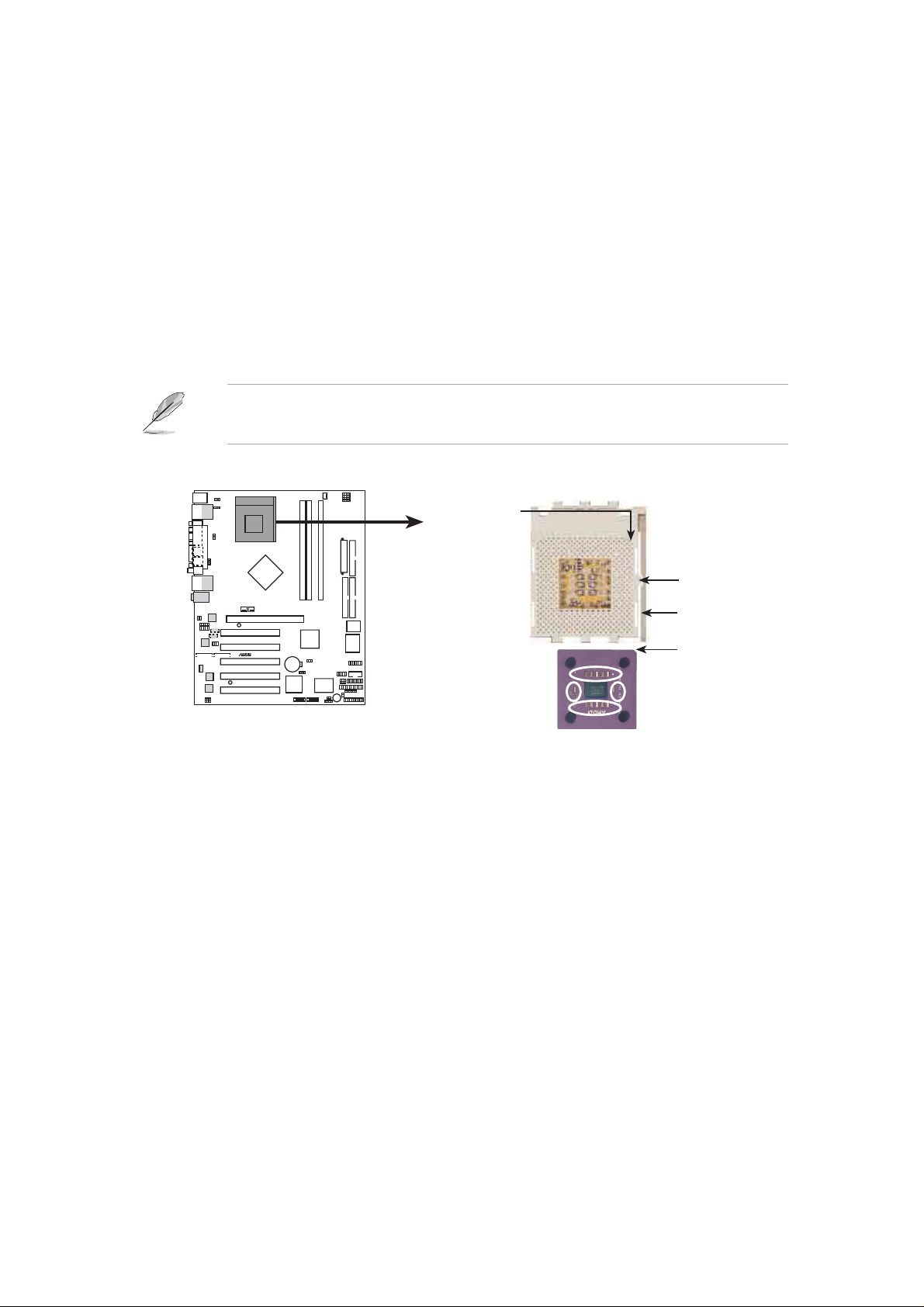
The motherboard provides a Socket A (462) for CPU installation. AMD
processors offer gigahertz speeds to support all the latest computing platforms
and applications. The A7N8X supports Athlon™ XP processors with
“QuantiSpeed” data processing, large data caches, 3D enhancements and
333/266Mhz bus speeds.
NOTE! Do not use processors with core speeds of less than 1GHz on
this motherboard.
CPU NOTCH
TO INNER
CORNER
LOCK
LEVER
A7N8X
A7N8X Socket 462
AMD™ CPU
CPU NOTCH
Each AMD CPU has a “marked” corner . This corner is usually indicated with
a notch, and/or a golden square or triangle. Refer to this indicator while
orienting the CPU. See the next page for installation details. A fan and
heatsink should be attached to the CPU to prevent overheating.
ASUS A7N8X motherboard user guide
11
Page 26
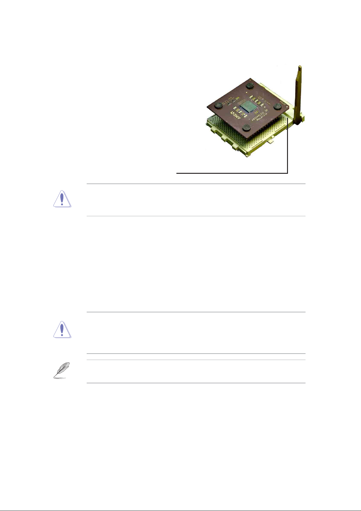
2.4.2 Installing the CPU
Follow these steps to install a CPU:
1. Locate the Socket 462 and open it by
pulling the lever gently sideways away
from the socket. Then lift the lever
upwards. The socket lever must be fully
opened (90 to 100 degrees).
2. Insert the CPU with the correct
orientation. The notched or golden
corner of the CPU must be oriented
toward the inner corner of the socket
base nearest to the lever hinge.
CAUTION! The CPU should drop easily into place. Do not force the
CPU into the socket to avoid bending the pins. If the CPU does not fit,
check its alignment and look for bent pins.
4. Once completely inserted, press the CPU firmly and close the socket
lever until it snaps shut.
5. Place the CPU fan and heatsink on the CPU. The heatsink should entirely
cover the CPU. Carefully attach the heatsink locking brace to the plastic
clips on the socket base. With the added weight of the CPU fan and
heatsink locking brace, no extra force is required to keep the CPU in
place
CAUTION! Take care not to scrape the motherboard surface when
mounting a clamp-style processor fan, or else damage may occur. When
mounting a heatsink onto your CPU, make sure that exposed CPU
capacitors do not touch the heatsink, or damage may occur!
NOTE! Do not neglect to set the correct Bus Frequency and leave the
CPU Multiple setting at default to avoid start-up problems.
12
Chapter 2: Hardware information
Page 27
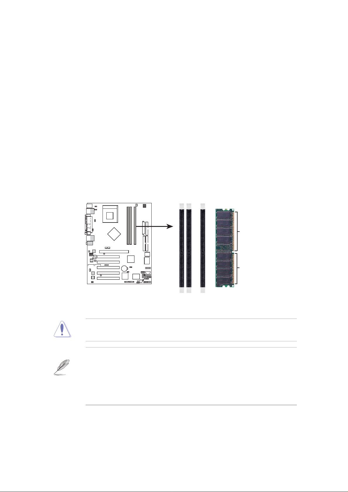
2.5 System memory
®
s
2.5.1 Overview
This motherboard uses only Double Data Rate (DDR) Synchronous Dynamic
Random Access Memory (SDRAM) Dual Inline Memory Modules (DIMMs).
These sockets support up to 1GB system memory using non-ECC PC400/
333/266/200 DIMMs.
Each DIMM socket/module is two-sided: each side defines one “row” of
memory. DIMMs come in combinations of single or double-sided types
ranging through 64MB, 128MB, 256MB, 512MB to form a total memory size
of 64MB to 1GB.
~ Three (3) sockets are available for 400MHz-PC3200, 333MHz-PC2700,
266MHz-PC2100, or 200MHz-PC1600 DDR DIMMs to form a memory size
of 64MB to 1GB.
104 Pin
A7N8X
A7N8X 184-Pin DDR
DIMM Sockets
CAUTION! DIMMs are keyed to fit into notches with only one direction.
DO NOT force a DIMM into a socket to avoid damaging the DIMM.
• DIMMs with more than 18 chips are not supported.
• DIMMs with more than 8 devices on each side of the module
are not supported.
• ASUS motherboards support SPD (Serial Presence Detect)DIMMs.
This is the memory of choice for best performance vs. stability
• BIOS shows DDR SDRAM memory on bootup screen.
80 Pins
ASUS A7N8X motherboard user guide
13
Page 28
2.5.2 Memory configurations
Install DIMMs in any of the following combinations.
DIMM Location 184-pin DIMM (DDR) Total Memory
Socket 1 (Rows 0&1) 64MB, 128MB, 256MB, 512MB, 1G x1
Socket 2 (Rows 2&3) 64MB, 128MB, 256MB, 512MB, 1G x1
Socket 2 (Rows 4&5) 64MB, 128MB, 256MB, 512MB, 1G x1
Total system memory (Max. 3GB) =
NOTE: To enhance system performance, utilize dual-channel feature
when installing additional DIMMs. You may install the DIMMs in the
following sequence: Sockets 1 and 3 or Sockets 2 and 3 or Sockets 1,
2 and 3.
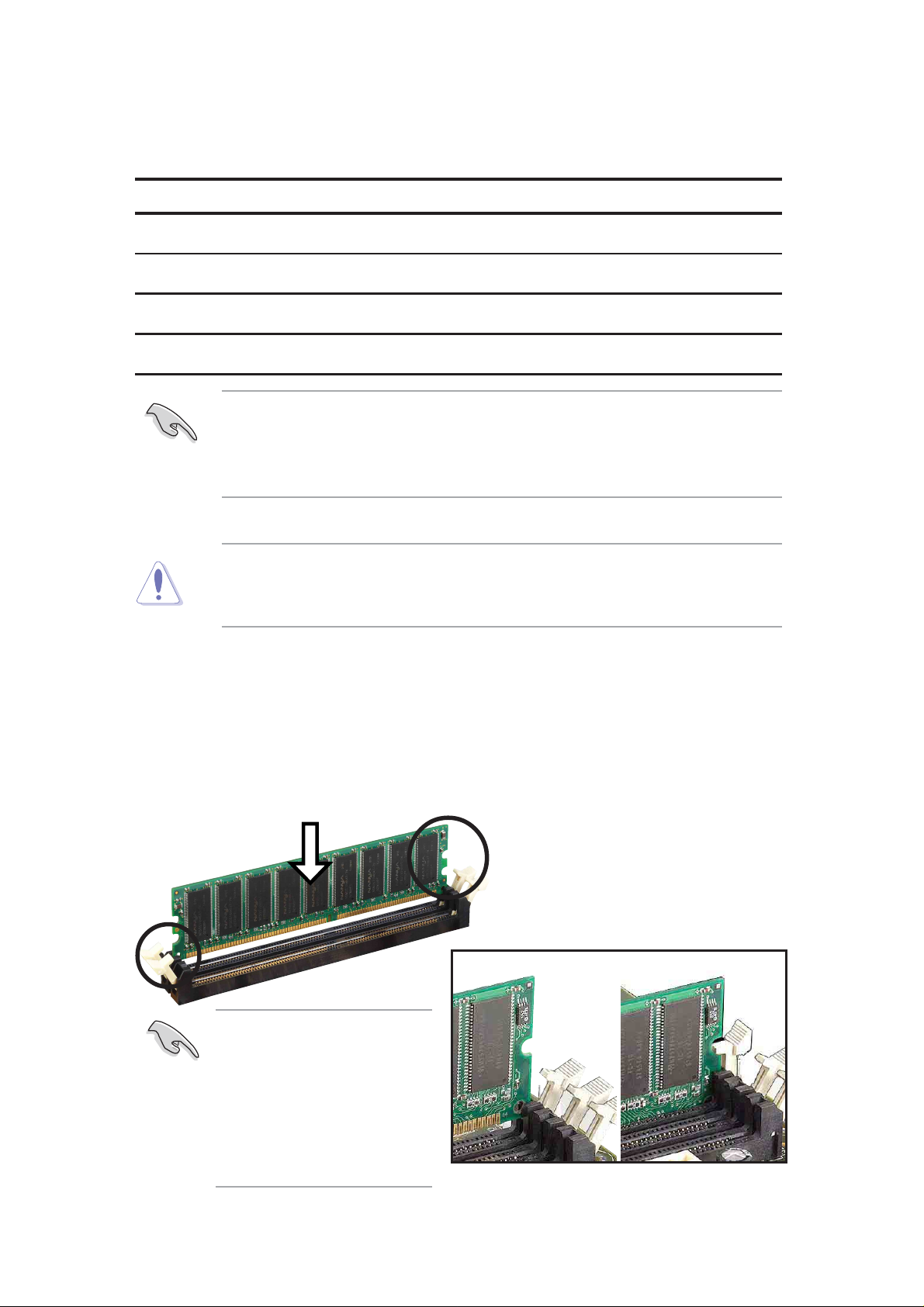
2.5.3 Installing a DIMM
CAUTION! Make sure to unplug the power supply before adding or
removing DIMMs or other system components. Failure to do so may cause
severe damage to both the motherboard and the components.
Installing a DIMM:
1. Unlock a DIMM socket by pressing the retaining clips outward.
2. Align a DIMM on the socket such that the notches on the DIMM exactly
match the notches in the socket.
3. Firmly insert the DIMM into the socket until the retaining clips snap back
in place.
14
NOTE: Visit the ASUS
website at www.asus.com
for the latest DIMM
Qualified Vendors List.
Make sure to use only
tested and qualified
DDR400 DIMMs.
Unlocked Retaining Clip Locked Retaining Clip
Chapter 2: Hardware information
Page 29
2.6 Expansion slots
The motherboard has five PCI slots and one Accelerated Graphics Port (AGP)
slot.. The following sub-sections describe the slots and the expansion cards
that they support.
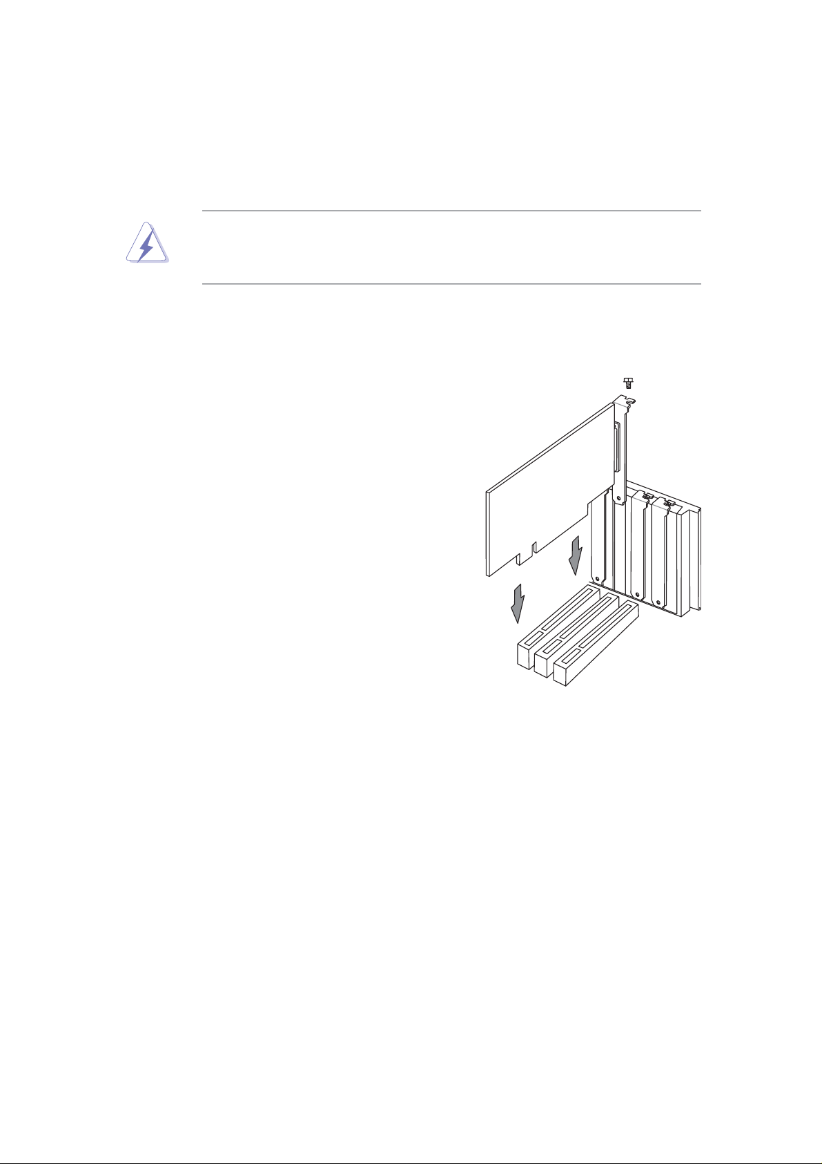
WARNING! Unplug your power supply when adding or removing
expansion cards or other system components. Failure to do so may cause
you physical injury and damage motherboard components.
2.6.1 Installing an expansion card
Follow these steps to install an expansion
card.
1. Before installing the expansion card, read
the documentation that came with it and
make the necessary hardware settings.
2. Remove the system unit cover (if your
motherboard is already installed in a
chassis).
3. Remove the bracket opposite the PCI slot.
Keep the screw for later use.
4. Align the card connector with the slot and
press firmly until the card is completely
seated on the slot.
5. Secure the card to the chassis with the
screw you removed earlier.
6. Replace the system cover.
7. Set up the BIOS if necessary.
8. Install the necessary software drivers for your expansion card.
ASUS A7N8X motherboard user guide
15
Page 30
2.6.2 Configuring an expansion card
Some expansion cards need an IRQ to operate. Generally , an IRQ must be
exclusively assigned to one function at a time. In a standard design
configuration, 16 IRQs are available but most are already in use. Normally,
6 IRQs are free for expansion cards. If the motherboard has PCI audio
onboard, an additional IRQ will be used. If your motherboard also has MIDI
enabled, another IRQ will be used, leaving 4 IRQs free. Sometimes IRQs
are “shared” by more than one function; in this case, IRQ assignments are
swapped automatically or adjusted through the BIOS firmware.
IMPORTANT! When using PCI cards on shared slots, ensure that the
drivers support “Share IRQ” or that the cards do not need IRQ
assignments. Otherwise, conflicts will arise between the three PCI groups,
making the system unstable and the card inoperative.
Standard Interrupt Assignments
IRQ Priority Standard Function
0 1 System Timer
1 2 Keyboard Controller
2 N/A Programmable Interrupt
3* 11 Communications Port (COM2)
4* 12 Communications Port (COM1)
5* 13 Sound Card (sometimes LPT2)
6 14 Floppy Disk Controller
7* 15 Printer Port (LPT1)
8 3 System CMOS/Real Time Clock
9* 4 ACPI Mode when used
10* 5 IRQ Holder for PCI Steering
11* 6 IRQ Holder for PCI Steering
12* 7 PS/2 Compatible Mouse Port
13 8 Numeric Data Processor
14* 9 Primary IDE Channel
15* 10 Secondary IDE Channel
*These IRQs are usually available for ISA or PCI devices.
16
Chapter 2: Hardware information
Page 31

Interrupt Request Table for this Motherboard
INT-A INT-B INT-C INT-D
PCI slot 1 shared — — —
PCI slot 2 — — — used
PCI slot 3 — shared —
PCI slot 4 — used — —
PCI slot 5 shared — —
Serial A T A — — shared —
2.6.3 PCI slots
Five 32-bit PCI slots are available on this motherboard. The slots support
PCI cards such as a LAN card, SCSI card, USB card, and other cards that
comply with PCI specifications.
This figure shows a typical PCI card installed into a slot:
ASUS A7N8X motherboard user guide
17
Page 32

®
2.6.4 AGP slot
This motherboard provides an Accelerated Graphics Port (AGP 8X) slot to
support AGP graphics cards. Take note of the notches on the card golden
fingers to ensure that they fit the AGP slot on your motherboard. Below is an
example of a +1.5V AGP card.
AGP Card without Retention Notch
A7N8X
TOP VIEW
20-pin bay
Rib (inside slot) Rib
A7N8X Accelerated
Graphics Port (AGP PRO)
28-pin bay
CAUTION! To avoid damaging your AGP graphics card, your computer’s
power supply should be unplugged before inserting your graphics card
into the slot.
18
Chapter 2: Hardware information
Page 33

®
t)
2.7 Jumpers
®
B
The jumpers on the motherboard allow you to change some feature
settings to suit your customized system configuration.
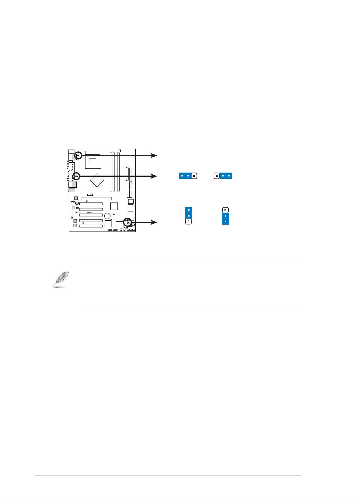
1) Serial ATA Setting (3 pin SATA_EN1)
This jumper permits selection of the serial ATA headers for connection of
serial ATA hard disk drives and other serial IDE devices. The default setting
[1-2] enables the serial headers. Disable the serial headers by changing
the jumpers to [2-3].
SATA_EN1
2
Disable
(Defaul
3
A7N8X
2
1
Enable
(Default)
A7N8X SATA Setting
2) Keyboard Wake Up (3 pin KBPWR1)
This allows you to disable or enable the keyboard power up function. Retain
the default setting of [1-2] to disable computer keyboard-wake-up function. If
you set to [2-3] you may use your keyboard by pressing <Spacebar> to
wake up your computer . This feature requires an ATX power supply that can
supply at least 1A on the +5VSB lead.
KBPWR1
2
1
+5V
(Default)
2
+5VS
3
A7N8X
A7N8X Keyboard Power Setting
ASUS A7N8X motherboard user guide
19
Page 34
3) USB Device Wake-up (2x3 pin USBPWR12, 34, 56)
®
USBPWR_12
B
Set these jumpers to +5V to allow wake up from the S1 sleep state (CPU
stopped; RAM refreshed; system running in low power mode) using the
connected USB devices. Set to +5VSB to allow wake up from S3 sleep state
(no power to CPU; RAM in slow refresh; power supply in reduced power
mode). The default setting for the three jumpers is 1-2 to select +5V (because
not all computers have the appropriate power supply).
The USBPWR01 jumper activates the rear panel USB ports. The USBPWR23
jumper activates the internal header, USB23
USBPWR_34
2
1
2
3
A7N8X
A7N8X USB Device Wake Up
NOTE! This feature requires an ATX power supply that can supply at
least 2A on the +5VSB lead when these jumpers are set to +5VSB.
Otherwise, the system does not power up. The total current consumed
must NOT exceed the power supply capability (+5VSB) whether under
normal working conditions or in sleep mode.
+5V
(Default)
USBPWR_56
1
2
+5V
(Default)
+5VSB
2
3
+5VS
20
Chapter 2: Hardware information
Page 35

4) Clear RTC RAM/CMOS (CLRTC1)
®
S
®
0
This jumper clears the Real T ime Clock (RTC) RAM of date, time, and system
setup parameters in CMOS. The RAM data in CMOS is powered by the
onboard button cell battery.
To erase the RTC RAM:
1. Turn OFF the computer and unplug the power cord.
2. Remove the battery.
3. Move the jumper caps from [1-2] to [2-3] momentarily. Replace the
jumper cap to the original position, [1-2].
4. Re-install the battery.
5. Plug the power cord and turn ON the computer.
6. Hold down the <Del> key during the boot process and enter BIOS
setup to re-enter data.
CLRTC1
12
A7N8X
Normal Clear CMO
(Default)
23
A7N8X Clear RTC RAM
5) Central Processing Unit FSB (CPU_FSB)
This jumper when set to 1-2 pins (default), enable support for Front Side
Bus 400/333/266. When set to pins 2-3, it sets support for FSB 200 only.
Support for FSB 400 is available to PCB 2.0 or later versions only.
CPU_FSB
1
A7N8X
2
FSB400/333/266 FSB20
(Default)
2
3
A7N8X CPU FSB Jumper Setting
ASUS A7N8X motherboard user guide
21
Page 36

2.8 Connectors
PS/2 Mouse (6-pin Female)
This section describes and illustrates the internal connectors on the
motherboard.
WARNING! Some pins are used for connectors or power sources. These
are clearly distinguished from jumpers in the Motherboard Layout. Placing
jumper caps over these connector pins will cause damage to your
motherboard.
IMPORTANT! Ribbon cables should always be connected with the red
stripe to Pin 1 in the connector scoket.
1) PS/2 Mouse Port (Green 6-pin PS2KBMS)
The system automatically directs IRQ12 to the PS/2 mouse if one is detected.
If no mouse is detected, IRQ12 become available to expansion cards.
2) PS/2 Keyboard Port (Purple 6-pin PS2KBMS)
This connection is for a standard keyboard using an PS/2 plug (mini DIN).
This connector does not allow standard AT size (large DIN) keyboard plugs.
You may use a DIN to mini DIN adapter on standard AT keyboards.
PS/2 Keyboard (6-pin Female)
22
Chapter 2: Hardware information
Page 37

3) Universal Serial Bus Ports 0 and 1 (Black four x 4-pin USB)
USB 2
USB 4
®
Four USB ports are available for connecting USB devices.
USB3
4) Serial Port and Header
Universal Serial Bus
(Teal/Turquoise, One 9-pin COM1, One 10-1 pin
USB1
COM2)
One serial port can be used for pointing devices or other serial devices. The
other is available as an onboard header . T o enable these ports, see Onboard
Serial Port 1 / Onboard Serial Port 2 in 4.4.3 Integrated Peripherals for
the settings.
COM1
Serial Ports (9-pin Male)
COM2
PIN 1
A7N8X
A7N8X Serial COM2 Bracket
ASUS A7N8X motherboard user guide
23
Page 38

Parallel Port (25-pin Female)
RJ-45RJ-45
5) Fast-Ethernet Port Connector (Two x RJ45) (Optional)
These RJ45 connectors are located on top of the USB Ports 1/2 and 3/
4. The RJ45 supports connectivity for local area networks.
3COM LAN NVIDIA LAN
6) Parallel Port (Burgundy 25-pin PRINTER)
You can enable the parallel port and choose the IRQ through Onboard
Parallel Port (see 4.4.3 Integrated Peripherals).
NOTE! Serial printers must be connected to the serial port.
24
Chapter 2: Hardware information
Page 39

®
t
7) Audio Connectors (Three 1/8” AUDIO) (Optional)
r
S/PDIF
c
t
For a 2-speaker audio output, the Line Out (lime) connects a headphone or
speakers. The Line In (light blue) connects a tape players or other audio
sources. The Mic (pink) connects a microphone.
In
Ou
Mi
For a 4 or 6 speaker audio output, the Line In (light blue) connects to other
audio sources. The Line Out (lime) connects to the Left/Right Front Speakers.
The Mic (pink) connects to a microphone. The Surround L/R audio connector
connects to the Left/Right Surround speakers. The Center/LFE connector
connects to the Center speakers or Bass speakers.
Center/Speaker
Bass Speaker
Connector
Surround Speaker
Left/Right
Line in
Front Speake
Left/Right
Microphone
NOTE! If you want to use 4/6 speaker output but only has 3 audio jacks
available on your back panel I/O, refer to Chapter 5.7.2.
8) IDE Activity LED (2-pin IDELED)
This connector supplies power to the cabinet’s IDE activity LED. Read and
write activity by devices connected to the Primary or Secondary IDE
connectors cause the IDE LED to light up.
IDELED1
A7N8X
A7N8X IDE Activity LED
ASUS A7N8X motherboard user guide
TIP: If the case-mounted LED does no
light, try reversing the 2-pin plug.
25
Page 40

9) Floppy Disk Drive Connector (34-1 pin FLOPPY)
®
n
®
s
This connector supports the provided floppy drive ribbon cable. After
connecting the single end to the board, connect the two plugs on the other
end to the floppy drives. (Pin 5 is removed to prevent inserting in the
wrong orientation when using ribbon cables with pin 5 plugged).
FLOPPY1
NOTE: Orient the red markings o
the floppy ribbon cable to
A7N8X
PIN 1
A7N8X Floppy Disk Drive Connector
PIN 1
10) Primary (Blue) / Secondary (Black) IDE Connectors
(40-1 pin PRI_IDE1 and SEC_IDE1)
The Primary and Secondary IDE connectors support the IDE hard disk ribbon
cables supplied with the motherboard. Connect the cable’s blue connector
to the motherboard’s primary IDE connector (recommended) or the secondary
IDE connector . Connect the opposite end of the cable to your UltraDMA133/
100/66 device (hard disk drive). If a second hard disk drive is connected,
youmay reset its jumper to Slave or Master/Slave mode. Non-UltraDMA133/
100/66 devices should be connected to the secondary IDE connector . BIOS
supports specific device bootup (see 4.4.1 Advanced BIOS Features).
IMPORTANT! UltraDMA133 IDE devices require a 40-pin 80-conductor
cable and RAID arrays only operate with such cables.
NOTE: Orient the red marking
(usually zigzag) on the IDE
ribbon cable to PIN 1.
A7N8X
SEC_IDE1
PIN 1
A7N8X IDE Connectors
26
PRI_IDE1
Chapter 2: Hardware information
Page 41

®
1
11) SATA Serial ATA Connectors (2 x 7-pin PRI_SATA1, SEC_SATA1)
®
)
(Optional)
Two headers support serial ATA133 devices including hard-drives and cdroms.
SEC_SATA1 PRI_SATA
A7N8X
GND
RSATA_TXN2
RSATA_TXP2
GND
RSATA_RXP2
RSATA_RXN2
GND
GND
RSATA_TXN1
RSATA_TXP1
GND
RSATA_RXP1
RSATA_RXN1
GND
A7N8X SATA Connectors
12) Infrared Module connector (10-1 or 10-2 pin IR_CON1)
These connectors support an optional wireless transmitting and receiving
infrared module. The module mounts to a small opening on the system chassis
that support this feature. You must also configure the UART2 Use As
parameter in BIOS to set UART2 for use with IR.
Use the ten pins as shown in Back View and connect a ribbon cable from the
module to the motherboard SIR connector according to the pin definitions.
IR_CON1
Standard Infrared (SIR)
Front View Back View
IRTX
GND
IRRX
+5V
(NC
A7N8X
SIR
CIR
+5 V
NC
GND
IRRX
NC
GND
IRTX
CIRRX
+5VSB
A7N8X Infrared Connector
ASUS A7N8X motherboard user guide
27
Page 42

13) CPU/Power/Chassis Fan Connectors (3-pin CPU_FAN1,
®
1
®
1
PWR_FAN1, CHA_FAN1)
Three fan connectors support cooling fans of 350mA (4.2 Watts) or less.
Orient the fans so that airflow flows across the onboard heat sinks instead of
expansion slots. The fan wiring and plug vary depending on the type
employed. Connect the fan cable to the connector, ensuring that the black
wire matches the ground pin. (Use the “Rotation” signal only with a specially
designed fan with a rotation signal. Y ou can monitor the Rotations Per Minute
(RPM) using ASUS PC Probe (see 5. SOFTWARE SUPPORT).
WARNING! Make sure to connect the fan cables to the fan connectors.
Lack of sufficient airflow within the system could cause damage to the
motherboard. These are not jumpers, do not place jumper caps over
these connectors!
CPU_FAN1
Rotation
+12V
GND
A7N8X
PWR_FAN1
GND
+12V
Rotation
CHA_FAN
GND
Rotation
+12V
A7N8X 12-Volt Cooling Fan Power
14) IEEE-1394 Header (8-pin 1394HEAD) (Optional)
This header supports an IEEE-1394 serial connector cable set that mounts
to a standard expansion slot in the computer case. 1394-compliant internal
fixed disk drives may also be connected to these headers.
IEEE1394_2
A7N8X
IEEE1394_
TPB2-
TPB2+
+12V
Ground
Ground
Ground
TPA2+
TPA2-
TPB2-
TPB2+
+12V
Ground
Ground
Ground
TPA2+
TPA2-
A7N8X 1394 Headers
28
Chapter 2: Hardware information
Page 43

15) Power Supply Connectors (20 pin block ATXPWR1)
®
ATXPWR1
®
This connector supports an A TX 12V power supply . The plug from the power
supply fits in only one orientation. Push down firmly ensuring that the pins
are aligned.
IMPORTANT! Make sure that the ATX 12V power supply offers at least
1A on the +5-volt standby lead (+5VSB). The minimum recommended
wattage is 230W or 300W for a fully configured system. The system may
become unstable and may experience difficulty powering up if the power
supply is inadequate.
+3.3VDC
+3.3VDC
COM
+5.0VDC
COM
+5.0VDC
COM
PWR_OK
+5VSB
+12.0VDC
A7N8X
+3.3VDC
-12.0VDC
COM
PS_ON#
COM
COM
COM
-5.0VDC
+5.0VDC
+5.0VDC
A7N8X ATX Power Connector
16) SMBus Connector (6-1 pin SMB)
This connector supports SMBus (System Management Bus) devices. SMBus
devices communicate by means of the SMBus with an SMBus host and/or
other SMBus devices. SMBus is a multi-device bus that permits multiple
chips to connect to the same bus and enable each one to act as a master by
initiating data transfer.
SMB1
A7N8X
A7N8X SMBus Connector
ASUS A7N8X motherboard user guide
1
SMBCLK
FLOATING
+3V
Ground
SMBDATA
29
Page 44

®
17) Internal Audio Connectors (Two x 4 pin CD1, AUX1, MODEM1)
®
)
These connectors allow you to receive stereo audio input from sound sources
as a CD-ROM, TV tuner, Modems, or MPEG card.
A7N8X
A7N8X Internal Audio Connectors
MODEM1 AUX1 (White
Ground
Modem-In
Ground
Modem-Out
CD1 (Black)
Ground
Left Audio Channel
Right Audio Channel
Ground
Left Audio Channel
Right Audio Channel
18) Digital Audio Interfaces (6 pin SPDIF1) (Optional)
This connector is for optional S/PDIF audio module that allows digital instead
of analog sound input and output.
GND
GND
1
SPDIF1
A7N8X
+5V
SPDIF_IN
SPDIF_OUT
A7N8X Digital Audio Connector
IMPORTANT! For S/PDIF out function, you may use either the module
or the S/PDIF connector at the back panel, but not both.
30
Chapter 2: Hardware information
Page 45

19) USB Headers (10-1 pin USB_56) (Optional)
®
®
d
If the USB 2.0 port connectors on the back panel are inadequate, one USB
header is available for four additional USB port connectors. Connect a 2port USB connector set to a USB header and mount the USB bracket to an
open slot in the chassis. (The USB connector set is optional and does not
come with the motherboard package.)
USB+5V
USB_P6-
USB_P6+
GND
A7N8X
A7N8X USB 2.0 Header
USB56
1
USB+5V
NC
GND
USB_P5-
USB_P5+
20) Power Supply Thermal Sensor (2-pin PWRTMP1) (Optional)
This header supports a thermal sensor for the power supply.
PWRTMP1
A7N8X
PWRTMP
A7N8X Power Supply Thermal Connector
Groun
ASUS A7N8X motherboard user guide
31
Page 46

®
21) Game Connector (16-1 pin GAME)
®
1
This connector supports an external game port. An example of a PCI game
port is illustrated.
GND
GND
+5V
A7N8X
GAME1
A7N8X Game Connector
J1CY
J1B2
J2B2
J2CY
MIDI_IN
J1CX
J1B1
+5V
+5V
J2B1
J2CX
MIDI_OUT
22) Chassis Open Alarm Lead (4-1 pin CHASSIS1)
This lead is intended for a chassis designed to support intrusion detection.
The lead requires an external detection mechanism such as a chassis
intrusion monitor/sensor or microswitch. When any chassis component is
removed, the sensor is triggered and a high-level signal is sent to this lead to
record a chassis intrusion event. The event is then be processed by software
such as LDCM. When not using the chassis intrusion lead, place a jumper
cap over the pins (PINS 3-4) to close the circuit. Removing the jumper cap
will prevent the system from booting up.
CHASSIS
A7N8X
Ground
Chassis Signal
+5Volt
(Power Supply Stand By)
1
A7N8X Chassis Open Alarm Lead
32
Chapter 2: Hardware information
Page 47

23) Front Panel Audio connector (10-1 pin FPAUDIO1)
®
1
®
This is an interface for the Intel front panel audio cable that allow convenient
connection and control of audio devices.
FPAUDIO
BLINE_OUT_L
BLINE_OUT_R
AGND
A7N8X
MIC2
MICPWR +5VA
Line out_R
NC
Line out_L
A7N8X Front Panel Audio Connector
The following 20-pin PANEL illustration is for items 24-29.
A7N8X
A7N8X System Panel Connectors
Keyboard Lock
Power LED
PLED+
SMI Lead
*
Requires an ATX power supply.
PLED-
Keylock
ExtSMI#
Ground
Ground
Speaker
Connector
Speaker
Ground
+5V
Ground
GND
PWR
Reset
Ground
Reset SW
ATX Power
Switch*
24) System Power LED Lead (3-1 pin PWR_LED)
This 3-1 pin connector supplies the system power LED. The LED lights up
when the system power is on, and the LED blinks when the system is in
sleep or soft-off mode.
25) Keyboard Lock Switch Lead (2 pin KEYLOCK)
This 2-pin connector supplies the case-mounted key switch for keyboard
locking.
26) System Warning Speaker Lead (4 pin SPEAKER)
This 4-pin connector supplies the case-mounted speaker to sound system
beeps and warnings.
ASUS A7N8X motherboard user guide
33
Page 48

27) System Management Interrupt Lead (2 pin SMI)
This 2-pin connector permits switching to suspend mode, or “Green” mode,
in which system activity is instantly decreased to save power and to expand
the life of certain system components. Attach the case-mounted suspend
switch this 2-pin connector.
28) ATX Power Switch / Soft-Off Switch Lead (2 pin PWR)
The system power is controlled by a momentary switch attached to this
connector . Pressing the button switches the system between ON and SLEEP ,
or ON and SOFT OFF, depending on the BIOS or OS settings. Pressing the
button while in the ON mode for more than 4 seconds turns the system off.
29) Reset Switch Lead (2 pin RESET)
This 2-pin connector supports the case-mounted reset switch for rebooting
the system without turning off the power switch.
34
Chapter 2: Hardware information
Page 49

Chapter 3
Powering up
Page 50

ASUS A7N8X motherboard
Page 51

3.1 Starting up for the first time
1. After making all the connections, replace the system case cover.
2. Be sure that all switches are off.
3. Connect the power cord to the power connector at the back of the
system chassis.
4. Connect the power cord to a power outlet that is equipped with a surge
protector.
5. Turn on the devices in the following order:
a. Monitor
b. External SCSI devices (starting with the last device on the chain)
c. System power (if you are using an ATX power supply, you need to
switch on the power supply as well as press the ATX power switch
on the front of the chassis).
6. After applying power, the power LED on the system front panel case
lights up. For ATX power supplies, the system LED lights up when you
press the ATX power switch. If your monitor complies with “green”
standards or if it has a “power standby” feature, the monitor LED may
light up or switch between orange and green after the system LED
turns on. The system then runs the power-on tests. While the tests are
running, the BIOS beeps or additional messages appear on the
screen. If you do not see anything within 30 seconds from the time you
turned on the power, the system may have failed a power-on test.
Check the jumper settings and connections or call your retailer for
assistance.
Award BIOS Beep Codes
Beep Meaning
One short beep when No error during POST
displaying logo
Long beeps in an endless loop No DRAM installed or detected
One long beep followed by Video card not found or video card
three short beeps memory bad
High frequency beeps when CPU overheated;
system is working System running at a lower frequency
7. At power on, hold down <Delete> to enter BIOS Setup. Follow the
instructions in Chapter 4.
ASUS A7N8X motherboard user guide
35
Page 52

3.2 Vocal POST Messages
This motherboard includes the Winbond speech controller to support a
special feature called the ASUS POST Reporter™. This feature gives you
vocal POST messages and alerts to inform you of system events and boot
status. In case of a boot failure, you will hear the specific cause of the
problem.
These POST messages are customizable using the Winbond Voice Editor
software that came with your package. You can record your own
messages to replace the default messages.
Following is a list of the default POST messages and their corresponding
actions, if any.
POST Message Action
No CPU installed • Install an AMD Thoroughbred/Athlon
XP/Athlon/ Duron Processor
into the CPU socket.
System failed CPU test • Check the CPU if properly installed.
• Call ASUS technical support for
assistance. See the “ASUS contact
information” on page x.
System failed memory test • Install 184-pin unbuffered
PC3200/2700/2100/1600 DIMMs
into the DIMM sockets.
• Check if the DIMMs on the DIMM
sockets are properly installed.
• Make sure that your DIMMs are
not defective.
• Refer to section “2.5 System
memory” for instruction on installing
a DIMM.
System failed VGA test • Install a PCI VGA card into one of
the PCI slots, or an AGP card
into the AGP slot.
• Make sure that your VGA/AGP card
is not defective.
System failed due to CPU • Check your CPU settings in BIOS
over-clocking and make sure you only set to the
recommended settings. See section
“4.4.2 Advanced Chipset features.”
36
Chapter 3: Powering up
Page 53

POST Message Action
No keyboard detected • Check your keyboard if properly
connected to the purple PS/2
connector on the rear panel.
• See section “1.4.1 Major
components” for the location of the
connector.
No floppy disk detected • Make sure you have connected a
floppy disk to the floppy disk
connector on the motherboard.
• See section “2.8 Connectors.”
No IDE hard disk detected • Make sure you have connected an
IDE hard disk drive to the one of the
IDE connectors on the motherboard.
• See section “2.8 Connectors.”
CPU temperature too high • Check CPU fan if working properly.
CPU fan failed • Check the CPU fan and make sure
it turns on after you applied power
to the system.
CPU voltage out of range • Check your power supply and
make sure it is not defective.
• Call ASUS technical support for
assistance. See the “ASUS contact
information” on page x.
System completed Power-On Self Test • No action required
Computer now booting from operating • No action required
system
You may disable the ASUS Speech POST Reporter™ in the BIOS
setup. See section “4.4.1 Advanced BIOS Features”.
ASUS A7N8X motherboard user guide
37
Page 54

3.3 Powering off the computer
You must first exit the operating system and shut down the system before
switching off the power. For ATX power supplies, you can press the ATX
power switch after exiting or shutting down the operating system. If you
use Windows 95/98/2000/XP, click the Start button, click Shut Down, then
click the OK button to shut down the computer. The power supply should
turn off after Windows shuts down.
The message “You can now safely turn off your computer” does not
appear when shutting down with ATX power supplies.
38
Chapter 3: Powering up
Page 55

Chapter 4
BIOS
Page 56

ASUS A7N8X motherboard
Page 57

4.1 Managing and updating your BIOS
4.1.1 Using the computer system for the first time
It is recommended that you save a copy of the original motherboard BIOS
along with a Flash Memory Writer utility (AWDFLASH.EXE) to a bootable
floppy disk in case you need to reinstall the BIOS later . AWDFLASH.EXE is
a Flash Memory Writer utility that updates the BIOS by uploading a new
BIOS file to the programmable flash ROM on the motherboard. This file
works only in DOS mode. T o determine the BIOS version of your motherboard,
check the last four numbers of the code displayed on the upper left-hand
corner of your screen during bootup. Larger numbers represent a newer
BIOS file.
1. T ype FORMAT A:/S at the DOS prompt to create a bootable system disk.
DO NOT copy AUTOEXEC.BAT and CONFIG.SYS to the disk.
2. T ype COPY D:\SOFTW ARE\AWDFLASH\AWDFLASH.EXE A:\ (assuming
D is your CD-ROM drive) to copy AWDFLASH.EXE to the boot disk you
created.
NOTE! AWDFLASH works only in DOS mode. It does not work in the
DOS prompt within Windows, and does not work with certain memory
drivers that may be loaded when you boot from the hard drive. It is
recommended that you reboot using a floppy in order to open DOS mode.
3. Reboot the computer from the floppy disk. To use AWDFLASH.EXE
must be operated from the ROOT directory. Therefore, copy the
AWDFLASH.EXE program and the NEW BIOS file to the root directory
on the hard disk drive; for example: type, “COPY A:\AWDFLASH.EXE
C:\” and “COPY A:\BIOSNAME.BIN C:\.
CAUTION!
• This motherboard uses the A7N8X Deluxe BIOS file for 4Mb flash
ROM. Another series model A7N8X uses the BIOS file for a 2Mb
flash ROM. Make sure to use the correct BIOS file on each model.
• PCB 2.0 BIOS version or later are not compatible with PCB 1.06 or
earlier BIOS versions.
NOTE! The PCB (Printed Circuit Board) version is located beside the
motherboard name printed on the motherboard.
WARNING! If you encounter problems while updating the new BIOS,
DO NOT turn off the system because this may cause boot problems.
Just repeat the process, and if the problem persists, load the original
BIOS file you saved to the boot disk, or try to clear the CMOS memory
(see section 2.7, Jumpers). If the Flash Memory Writer utility is not able
to successfully update a complete BIOS file, the system may not boot. If
this happens, call the ASUS service center for support.
ASUS A7N8X motherboard user guide
39
Page 58

4.1.2 Updating BIOS procedures
CAUTION! Update the BIOS only if you have problems with the
motherboard and you are sure that the new BIOS revision will solve your
problems. Careless updating may create more problems !
The Binary Input/Output System (BIOS) can be updated using the built-in
Flash Memory Writer utility or using a bootable floppy disk with the
executable Flash Memory Writer Utility (AWDFLASH.EXE). The following
sub-sections explain the steps in flashing your BIOS.
4.1.2.1 Updating BIOS via Built-in AwardBIOS Flash Utility
1. Download the latest BIOS file from the ASUS website (see ASUS contact
info on Page viii). Save the copy to a floppy disk.
NOTE! Write down the BIOS file name on a piece of paper . You need to
type the exact BIOS file name at the Award BIOS Flash Utility.
2. Reboot the computer.
3. To use AwardBIOS Flash Utility, press <Alt> + <F2> during POST to
display the following screen.
NOTE! The BIOS information in the above screen is for reference only.
what you see on your screen may not be exactly the same as shown.
4. Insert the disk that contains the new BIOS file into the floppy drive. You
will receive the error message, “WARNING! Device not ready!” if you
proceed to step 5 without the disk in the drive.
40
Chapter 4: BIOS Setup
Page 59

5. Type the name of the new BIOS file, for example: “AW0702.BIN” then
press <Enter>. The program asks if you want to save the previous BIOS.
Select <Y> since it is advisable to back-up the original BIOS in case you
need to reprogram it.
6. The program asks to save the previous BIOS to a separate file. Type a
file name for the old bios and then press <Y>. The AWDFLASH
program backs-up the file.
7. AWDFLASH proceeds to check the new BIOS file and asks the user to
program (flash) the new BIOS file to the motherboard.
ASUS A7N8X motherboard user guide
41
Page 60

8. Type <Y> and Press <Enter> to flash the new Bios file. NOTE: Do not
shut off system power or unplug the supply during the flash process.
9. The BIOS flashes and displays the results. Press <F1> to restart.
4.1.2.2 Updating BIOS via Bootable Floppy Disk
1. Boot from the floppy disk.
2. At the “A:\” prompt, type “C:\” and then press <Enter>.
3. At the “C:\” prompt, type “AWDFLASH /qi BIOSFILE” and then <Enter>.
For example: “AWDFLASH /qi aw0702.bin” The AWDFLASH screen
appears, and the BIOS file appears in the space, “File Name to Program”.
4. Type the name of the new BIOS file, for example: “AW0702.BIN” then
press <Enter>. The program asks if you want to save the previous BIOS.
Select <Y> since it is advisable to back-up the original BIOS in case you
need to reprogram it.
5. Follow steps 6 to 9 in “4.1.2.1 Updating BIOS via Built-in Award BIOS
Flash Utility.”
42
Chapter 4: BIOS Setup
Page 61

4.2 BIOS Setup program
This motherboard supports a programmable FLASH ROM that you can update
using the provided utility described in section “4.1 Managing and updating
your BIOS.”
Use the BIOS Setup program when you are installing a motherboard,
reconfiguring your system, or prompted to “Run Setup”. This section explains
how to configure your system using this utility.
Even if you are not prompted to use the Setup program, you may want to
change the configuration of your computer in the future. For example, you
may want to enable the security password feature or make changes to the
power management settings. This requires you to reconfigure your system
using the BIOS Setup program so that the computer can recognize these
changes and record them in the CMOS RAM of the FLASH ROM.
The FLASH ROM on the motherboard stores the Setup utility. When you
start up the computer, the system provides you with the opportunity to run
this program. Press <Delete> during the Power-On Self Test (POST) to enter
the Setup utility, otherwise, POST continues with its test routines.
If you wish to enter Setup after POST, restart the system by pressing <Ctrl>
+ <Alt> + <Delete>, or by pressing the reset button on the system chassis.
You can also restart by turning the system off and then back on. Do this last
option only if the first two failed.
The Setup program is designed to make it as easy to use as possible. It is a
menu-driven program, which means you can scroll through the various submenus and make your selections among the predetermined choices.
NOTE! Because the BIOS software is constantly being updated, the
following BIOS setup screens and descriptions are for reference purposes
only, and may not exactly match what you see on your screen.
ASUS A7N8X motherboard user guide
43
Page 62

4.2.1 BIOS menu bar
The top of the screen has a menu bar with the following selections:
MAIN Use this menu to make changes to the basic system
configuration.
ADVANCED Use this menu to enable and make changes to the
advanced features, including BIOS, Chipset, Peripheral,
Power and PnP/ PCI configurations.
SECURITY Use this menu to set the Supervisor and User passwords.
HARDWARE Monitor the status of vital components, including voltages
and fan speeds.
EXIT Use this menu to exit the current menu or to exit the Setup
MONITOR
program.
T o access the menu bar items, press the right or left arrow key on the keyboard
until the desired item is highlighted.
4.2.2 Legend bar
At the bottom of the Setup screen is a legend bar . The keys in the legend bar
allow you to navigate through the various setup menus. The following table
lists the keys found in the legend bar with their corresponding functions.
Navigation Key(s) Function Description
<F1> Displays the General Help screen
<Esc> Jumps to the Exit menu or returns to the main
menu from a sub-menu
Left or Right arrow Selects the menu item to the left or right
Up or Down arrow Moves the highlight up or down between fields
Page Down and – (minus) Scrolls backward through the values for the
highlighted field
Page Up and + (plus) Scrolls forward through the values for the high-
lighted field
<Enter> Brings up a selection menu for the highlighted
field
<F10> Saves changes and Exit
44
Chapter 4: BIOS Setup
Page 63

General help
In addition to the Item Specific Help window, the BIOS setup program also
provides a General Help screen. You may launch this screen from any menu
by simply pressing <F1> or the <Alt> + <H> combination. The General Help
screen lists the legend keys and their corresponding functions.
Saving changes and exiting the Setup program
See “4.7 Exit Menu” for detailed information on saving changes and exiting
the setup program.
Scroll bar
When a scroll bar appears to the right of a help window, it indicates that
there is more information to be displayed that will not fit in the window. Use
<PgUp> and <PgDn> or the up and down arrow keys to scroll through the
entire help document. Press <Home> to display the first page, press <End>
to go to the last page. To exit the help window, press <Enter> or <Esc>.
Sub-menu
Note that a right pointer symbol (as shown on
the left) appears to the left of certain fields.
This pointer indicates that you can display a
sub-menu from this field. A sub-menu contains
additional options for a field parameter. To
display a sub-menu, move the highlight to the
field and press <Enter>. The sub-menu
appears. Use the legend keys to navigate and
enter values within each sub-menu as you
would within a menu. Use the <Esc> key to
return to the main menu. Take some time to
familiarize yourself with the legend keys and
their corresponding functions. Practice navigating through the various menus
and sub-menus. While moving around through the Setup program, note that
explanations appear in the Item Specific Help window located to the right of
each menu. This window displays the help text for the currently highlighted
field.
ASUS A7N8X motherboard user guide
45
Page 64
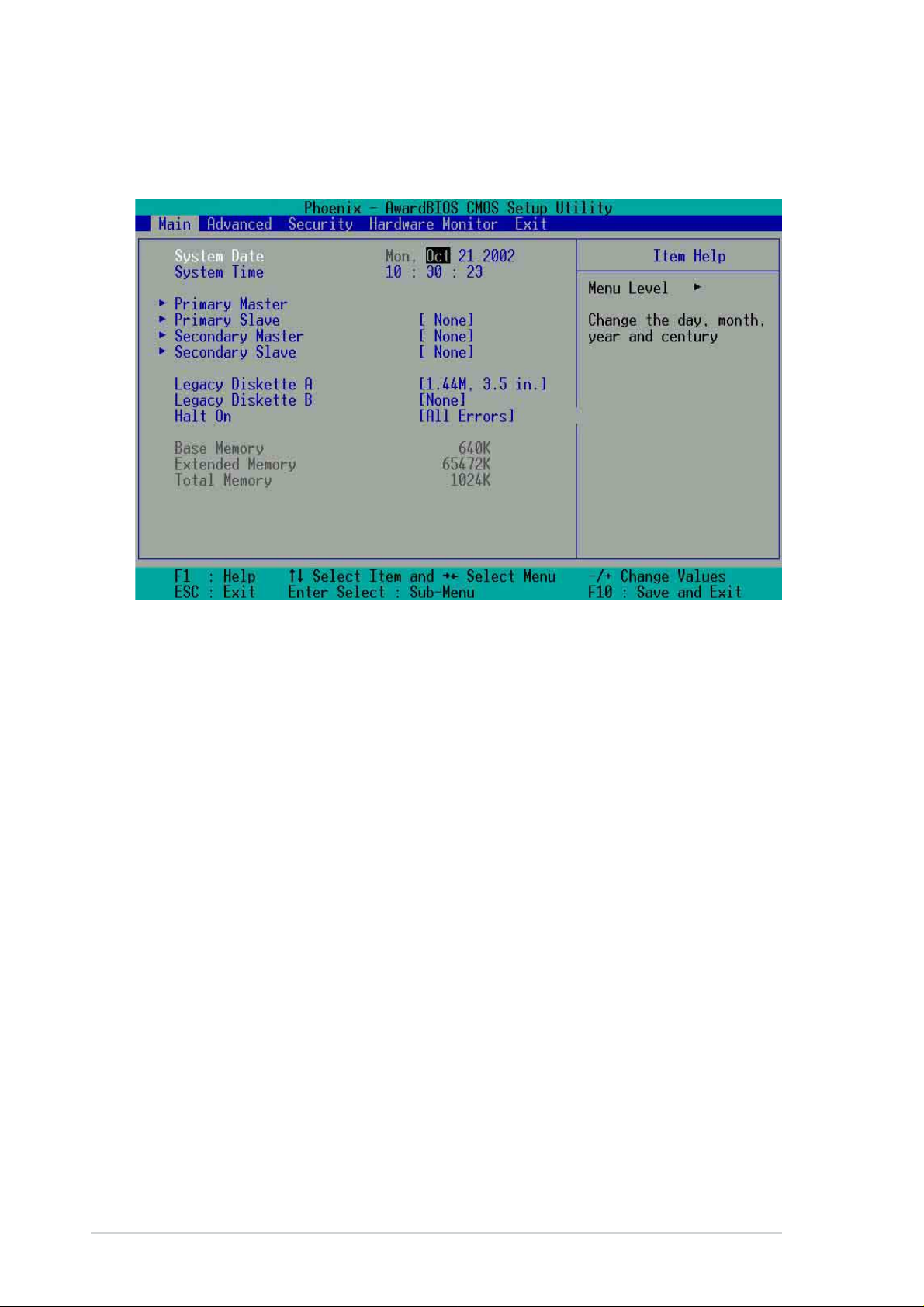
4.3 Main Menu
When you enter the Setup program, the following screen appears.
System Date [mm/dd/yy]
Sets the system to the date that you specify (usually the current date). The
format is month, day , year . Valid values for month, day, and year are Month:
(1 to 12), Day: (1 to 31), Year: (up to 2084). Use the <Tab> or <Shift> +
<Tab> keys to move between the month, day, and year fields.
System Time [hh:mm:ss]
Sets the system to the time that you specify (usually the current time). The
format is hour, minute, second. Valid values for hour, minute and second are
Hour: (00 to 23), Minute: (00 to 59), Second: (00 to 59). Use the <Tab> or
<Shift> + <Tab> keys to move between the hour, minute, and second fields.
Legacy Diskette A [1.44M, 3.5 in.]
Sets the type of floppy drive installed. Configuration options: [None] [360K,
5.25 in.] [1.2M , 5.25 in.] [720K , 3.5 in.] [1.44M, 3.5 in.] [2.88M, 3.5 in.]
Legacy Diskette B [None]
Sets the type of floppy drive installed. Configuration options: [None] [360K,
5.25 in.] [1.2M , 5.25 in.] [720K , 3.5 in.] [1.44M, 3.5 in.] [2.88M, 3.5 in.]
Halt On [All Errors]
This field sets the system to halt on errors according to the system functions
specified in each option. Configuration options: [All Errors] [No Errors] [All,
But Keyboard] [All , But Diskette] [All, But Disk/Key]
46
Chapter 4: BIOS Setup
Page 65

4.3.1 Primary Master/Slave
IDE HDD Auto-Detection [Press Enter]
Press enter to automatically detect an IDE hard disk drive, if the hard drive is
not already detected. In cases of undetected HDDs, pressing enter will detect
the HDD and then open access to both the IDE Primary Master and Access
Mode fields.
IDE Primary Master/Slave [Auto]
Select [Auto] to automatically detect an IDE hard disk drive. If automatic
detection is successful, the setup BIOS automatically fills in the correct values
for the remaining fields on this sub-menu. If automatic detection fails, this
may be because the hard disk drive is too old or too new . If the hard disk was
already formatted on a previous system, the setup BIOS may detect incorrect
parameters. In these cases, select [Manual] to manually enter the IDE hard
disk drive parameters. See Access Mode below and refer to the next page
for more details. If no drive is installed or if you are removing a drive and not
replacing it, select [None]. Configuration options: [None] [Auto [Manual]
Access Mode [Auto]
The default [Auto] automatically detects an IDE hard disk drive. Select [CHS]
in coordination with the [Manual] setting of the IDE Primary Master in order
to enter the Hard Disk Drive values manually.
CAUTION! Before attempting to configure a hard disk drive, make sure
you have the correct configuration information supplied by the drive
manufacturer. Incorrect settings may cause the system to fail to recognize
the installed hard disk.
ASUS A7N8X motherboard user guide
47
Page 66

[Manual] & [CHS] Settings
Manually enter the number of cylinders, heads and sectors per track for the
drive. Refer to the drive documentation or on the drive label for this information.
NOTE! After entering the IDE hard disk drive information into BIOS, use
a disk utility, such as FDISK, to partition and format new IDE hard disk
drives. This is necessary so that you can write or read data from the hard
disk. Make sure to set the partition of the Primary IDE hard disk drives to
active.
After making your selections on this sub-menu, press the <Esc> key to return
to the Main menu. When the Main menu appears, the hard disk drive field
displays the size for the hard disk drive that you configured.
Access Mode [Auto]
Select the hard disk drive type in this field. When Logical Block Addressing
(LBA) is enabled, the 28-bit addressing of the hard drive is used without
regard for cylinders, heads, or sectors. Note that LBA Mode is necessary for
drives with more than 504MB storage capacity . Select [CHS] to make manual
entries for configuring the fields below. Configuration options: [CHS] [LBA]
[Large] [Auto]
Cylinders
This field configures the number of cylinders. Refer to the drive documentation
to determine the correct value. To make changes to this field, set the IDE
Primary Master field to [Manual] and the Access Mode to [CHS].
48
Chapter 4: BIOS Setup
Page 67

Head
This field configures the number of read/write heads. Refer to the drive
documentation to determine the correct value. To make changes to this
field, set the IDE Primary Master field to [Manual] and the Access Mode to
[CHS].
Precomp
This field displays the precompressed volumes on the hard disk, if any, in
MB.
Landing Zone
This field displays the drive’s maximum useable capacity as calculated by
the BIOS based on the drive information you entered.
Sector
This field configures the number of sectors per track. Refer to the drive
documentation to determine the correct value. To make changes to this field,
set the Type field to [User Type HDD] and the Translation Method field to
[Manual].
ASUS A7N8X motherboard user guide
49
Page 68

4.3.2 Secondary Master/Slave
IDE HDD Auto-Detection [Press Enter]
Press enter to automatically detect an IDE hard disk drive, if the hard drive is
not already detected. In cases of undetected HDDs, pressing enter will detect
the HDD and then open access to both the IDE Primary Master and Access
Mode fields.
IDE Secondary Master/Slave [Auto]
Select [Auto] to automatically detect an IDE hard disk drive. If automatic
detection is successful, the setup BIOS automatically fills in the correct values
for the remaining fields on this sub-menu. If automatic detection fails, this
may be because the hard disk drive is too old or too new . If the hard disk was
already formatted on a previous system, the setup BIOS may detect incorrect
parameters. In these cases, select [Manual] to manually enter the IDE hard
disk drive parameters. See Access Mode below and refer to the next page
for more details. If no drive is installed or if you are removing a drive and not
replacing it, select [None]. Configuration options: [None] [Auto [Manual]
Access Mode [Auto]
The default [Auto] automatically detects an IDE hard disk drive. Select [CHS]
in coordination with the [Manual] setting of the IDE Primary Master in order
to enter the Hard Disk Drive values manually.
CAUTION! Before attempting to configure a hard disk drive, make sure
you have the correct configuration information supplied by the drive
manufacturer. Incorrect settings may cause the system to fail to recognize
the installed hard disk.
50
Chapter 4: BIOS Setup
Page 69

4.4 Advanced Menu
Advanced menu items
The Advanced menu accesses five important sub-menus:
Advanced BIOS Features
These fields set the functional properties of CPU caches, as well as boot
devices, security and operational modes.
Advanced Chipset Features
These fields set chipset and CPU functions, including system and AGP
caches, boot devices, memory settings, voltages and frequencies.
Integrated Peripherals
These fields set the functional properties of the IDE channels, Master/Slave
PIOs, USB, IEEE 1394, audio, network and modem support, as well as serial,
game, midi and parallel addresses.
Power Management Setup
These fields set the functional properties of the ACPI, system power
management, HDD power, network “wake-up” and “power-on” options.
PnP/PCI Configuration
These fields set the capacity of the BIOS to reset data configurations and to
automatically configure the system along with PCI/VGA properties. IRQ
resources are accessed from this menu.
To access the menu bar items, press the up and down arrow keys and then
press <enter> to view the desired menu.
ASUS A7N8X motherboard user guide
51
Page 70

4.4.1 Advanced BIOS Features
(Scroll down to view all items on the menu.)
Boot Virus Detection [Disabled]
This field enables boot virus protection by default. Configuration options:
[Enabled] [Disabled]
CPU Level 1 Cache [Enabled]
This field enables the CPU level 1 cache by default. Configuration options:
[Enabled] [Disabled]
CPU Level 2 Cache [Enabled]
This field enables the level 2 cache by default. Configuration options:
[Enabled] [Disabled]
Quick Power On Self Test [Enabled]
This field enables the power on test. Configuration options: [Enabled]
[Disabled]
First Boot Device [Floppy]
This field sets the priority of the first boot device; by default, the system
boots up on the floppy diskette drive. Configuration options: [Floppy] [LS120]
[HDD] [SCSI] [CDROM] [ZIP100] [LAN] [Disabled]
52
Chapter 4: BIOS Setup
Page 71

Second Boot Device [HDD]
This field sets the priority of the second boot device; by default, the system
boots up on the hard disk driver if the floppy drive is not present. Configuration
options: [Floppy] [LS120] [HDD] [SCSI] [CDROM] [ZIP100] [LAN] [Disabled]
Third Boot Device [LS120]
This field sets the priority of the third boot device; by default, the system
boots up on the LS120 if the flopyy and hard disk drive are not present.
Configuration options: [Floppy] [LS120] [HDD] [SCSI] [CDROM] [ZIP100]
[LAN] [Disabled]
Boot Other Device [Enabled]
By default, this field enables the detection of other devices, aside from the
first three priority devices. Configuration options: [Enabled] [Disabled]
Boot-up Floppy Seek [Enabled]
If enabled, this field speeds up the Power On Self Test (POST) routine by
skipping and retesting a second, third and fourth time. Configuration options:
[Enabled] [Disabled]
Boot-up NumLock Status [On]
This field sets the capability of the NumLock light/key to display/activate the
system. Configuration options: [On] [Off]
Gate A20 Option [Fast]
This field sets the gate A20 rate. The default is [Fast]. Configuration options:
[Normal] [Fast]
Typematic Rate Setting [Disabled]
This field enables or disable permission to change the rate of keystroke
registration and display . By default, the rate cannot be changed. Change to
[Enabled] to make settings in the nextt field. Configuration options: [Enabled]
[Disabled]
Typematic Rate Setting (Char/Sec) [6]
This field determines the number of keystrokes per second that the system
can register. Configuration options: [6] [8] [10] [12] [15] [20] [24] [30]
Typematic Delay (Msec) [250]
This field determines the delay time ( in milliseconds ) between registering a
keystroke and displaying it onscreen. Configuration options: [250] [500] [750]
[1000]
APIC Mode [Enabled]
This field enables or disables the APIC mode. Configuration options:
[Enabled] [Disabled]
ASUS A7N8X motherboard user guide
53
Page 72

OS/2 Onboard Memory > 64MB [Disabled]
This field enables or disables the 64MB onboard memory set for OS/2.
Configuration options: [Disabled] [Enabled]
Full Screen LOGO Show [Enabled]
This field enables or disables display of the full screen logo for environmental
protection, which is disabled by default.
Configuration options: [Enabled] [Disabled]
POST Complete Report [Enabled]
This field enables or disables display of the Power On Self Test (POST)
complete report, which is [Enabled] by default.
Configuration options: [Enabled] [Disabled]
Speech POST Reporter [Enabled]
This field enables or disables the ASUS POST ReporterTM feature.
Configuration options: [Enabled] [Disabled]
54
Chapter 4: BIOS Setup
Page 73

4.4.2 Advanced Chipset Features
(Scroll down to view all items on the menu.)
CPU External Frequency (MHz) [100MHz]
This field sets the external frequency ratio of the CPU. The system normally
auto-detects the frequency capability based on the type of CPU installed.The
Front Side Bus (FSB) is equal to 2 times this field value. Frequency ranges
are adjustable in increments of 1, 2, 3 and/or 5 MHz. Configuration options:
[100 MHz]... [200 MHz] [204 MHz] [207 MHz] [211 MHz]
CPU Frequency Multiple Setting [Auto]
This field sets the frequency multiple between the CPU’s internal frequency
(CPU speed) and external frequency. Set this field in conjunction with CPU
Frequency (MHz) to match the speed of the CPU.
CPU Frequency Multiple [5.0x]
This field is available to unlocked processors only . For unlocked processors,
this field sets the frequency multiple between the CPU’s internal frequency
(CPU speed) and the external frequency . Configuration options: [5.0x] [5.5x]...
...[11.5] [12.0] [12.5x/13.0x]
ASUS A7N8X motherboard user guide
55
Page 74

System Performance [Optimal]
This field permits change of mode for system performance. When set to
[Optimal], the system uses the most stable settings. When you want to use
overclocked settings for higher performance but with higher risk of instability ,
set to [Aggressive] and to allow full customization of performance options
set to [Expert]. Configuration options: [Optimal] [Aggressive] [User Defined]
CPU Interface [Optimal]
This field sets the mode for CPU/FSB parameters usage. Select [Aggressive]
if you want to use overclocked CPU/FSB parameters. Otherwise, the default
value is [Optimal] where it uses the most stable CPU/FSB parameters.
Configuration options: [Optimal] [Aggressive]
Memory Frequency [By SPD]
This field sets the type of memory frequency based on the type of DDR
(Double Date Rate) memory module installed. Resulting frequency can vary
depending on percentage setting which is multiplied by the FSB frqequency .
Normally , the default, by SPD, permits autodetection. Configuration options:
[By SPD] [50%] [60%] [66%] [75%] [80%] [83%] [Sync] [120%] [125%] [133%
[150%] [166%] [200%]
Resulting Frequency
This field displays the resulting memory frequency
Memory Timing [Optimal]
This field permits change of memory timing mode for system performance.
When set to [User Defined], the next four fields can be set manually. Set to
[Aggressive] for higher performance. Use default [Optimal] to use most stable
settings. Configuration options: [Optimal] [Aggressive] [User Defined]
SDRAM Active Precharge Delay [7]
Row-active delay.
SDRAM RAS to CAS Delay [1]
RAS-to-CAS. This item controls the latency between the SDRAM Active
command to the SDRAM.
SDRAM RAS Precharge Delay [1]
Row-precharge delay.
SDRAM CAS Latency [2.5T]
This field sets the override clock cycle for the latency time between the
SDRAM read command and the moment that the data actually becomes
available. Normally , the system determines the rate automatically by default.
FSB Spread Spectrum [Disabled]
Configuration options: [Disabled] [0.50%] [1.00%]
AGP Spread Spectrum [Disabled]
Configuration options: [Disabled] [0.50%] [1.00%]
56
Chapter 4: BIOS Setup
Page 75

CPU Vcore Setting [Auto]
This field determines if the CPU Vcore is automatically scaled or set manually
by the user. The default for this field is [Auto], therefore, the CPU vcore
voltage is set for maximum performance without stressing the CPU.
Configuration options: [Auto] [Menu]
CPU Vcore [1.850V]
When the CPU VCore Setting parameter is set to [Manual], this field permits
selection of specific CPU core voltages. This field is not accessible if the
above CPU VCore Setting parameter is set to [Auto]. Configuration options:
[1.100V] [1.125V] ... [1.825] [1.850V]
Graphics Aperture Size [64M]
This field sets the size of mapped memory ( in megabytes ) for AGP graphic
data. Configuration options: [32M] [64M] [128M] [256M] [512M]
AGP Frequency [Auto]
This field sets the frequency of the AGP controller. The default, [Auto],
permits automatic selection of optimal AGP frequencies. Configuration
options: [50, 66, 67, 68, 69, 70, 71, 72, 73, 74, 75, 76, 77, 78, 79, 80, 81, 82, 83, 84, 85, 86,
87, 90, 93, 95, 97, 100MHz]
System BIOS Cacheable [Disabled]
This field establishes whether or not the BIOS is cacheable. Disabled by
default. Configuration options: [Enabled] [Disabled]
Video RAM Cacheable [Disabled]
This field establishes whether or not the video RAM is cacheable. Disabled
by default. Configuration options: [Enabled] [Disabled]
DDR Reference Voltage [ 2.6V]
This field sets the voltage limits for the voltage supplied to the DDR memory .
Note that increasing voltage to the DDR can cause premature failure of system
components. Configuration options: [2.6V] [2.7V] [2.8V]
AGP VDDQ Voltage [1.5V]
This field sets the voltage limits for the voltage supplied to the AGP controller .
Note that increasing voltage to the AGP controller can cause premature failure
of system components.
Configuration options: [1.5V] [1.6V] [1.7V]
AGP 8X Support [Enabled]
This field enables or disables the AGP 8X support.
Configuration options: [Disable] [Enable]
AGP Fast Write Capability [Enabled]
This field enables or disables the AGP Fastwrite function.
Configuration options: [Disable] [Enable]
ASUS A7N8X motherboard user guide
57
Page 76

4.4.3 Integrated Peripherals
(Scroll down to view all items on the menu.)
Primary VGA BIOS [PCI VGA Card]
This field sets the priority for the display of VGA signals. Change from the
PCI VGA Cardt default to AGP VGA Card if using an AGP card.
Configuration options: [PCI VGA Card] [AGP VGA Card]
USB Controllers [V1.1+V2.0]
This field sets the protocols for OnChip processing of USB outputs. The
default accomodates USB protocols 1.0 and 2.0. Configuration options:
[Disabled] [V1.1 +V2.0] [V1.1]
USB Legacy Support [Disabled]
This field sets support for USB keyboards0. The USB keyboard is disabled
by default. Enable this field to use a USB keyboard. Configuration options:
[Enabled] [Disabled]
USB Mouse Support [Disabled]
This field sets support for USB keyboards0. The USB keyboard is disabled
by default. Enable this field to use a USB keyboard. Configuration options:
[Enabled] [Disabled]
58
Chapter 4: BIOS Setup
Page 77

Onboard AC97 Audio Controller [Auto]
This field permits auto selection of AC97 audio codec processing by default.
Configuration options: [Auto] [Disabled]
Onboard AC97 Modem Controller [Auto]
This field permits auto selection of AC97 modem support by default.
Configuration options: [Auto] [Disabled]
Onboard Lan (nVIDIA) [Auto]
This field permits auto selection of MAC Lan (nVidia) support by default.
Configuration options: [Auto] [Disabled]
Onboard Lan (3COM) [Auto]
This field permits auto selection of MAC lan (3COM) ethernet. Configuration
options: [Auto] [Disabled]
Onboard 1394 Device [Enabled]
This field sets the on chip suppot for IEEE 1394 signal outputs by default.
Configuration options: [Enabled] [Disabled]
Floppy Disk Access Controller [Enabled]
This field enables the FDA Controller by default. Configuration options:
[Enabled] [Disabled]
Onboard Serial Port 1 [3F8/IRQ4]
These fields set the addresses for onboard serial port 1. Serial Port 1 and
Serial Port 2 must have different addresses. Configuration options: [Disabled]
[3F8/IRQ4] [2F8/IRQ3] [3E8/IRQ4] [2E8/IRQ3] [Auto]
Onboard Serial Port 2 [2F8/IRQ3]
These fields set the addresses for onboard serial port 2. Serial Port 1 and
Serial Port 2 must have different addresses. Configuration options: [Disabled]
[3F8/IRQ4] [2F8/IRQ3] [3E8/IRQ4] [2E8/IRQ3] [Auto]
UART use as [COM Port]
This field selects the device assignment for UART2 mode. The default is
[COM Port]. Select [IR] to activate the next field, “UR2 Duplex Mode”.
Configuration options: [IR] [COM Port]
Onboard Parallel Port [378/IRQ7]
This field sets the address of the onboard parallel port connector to 378/
IRQ7 by default. Disabling the port makes the parallel port unavailable.
Configuration options: [Disabled] [378/IRQ7] [278/IRQ5] [3BC/IRQ7]
ASUS A7N8X motherboard user guide
59
Page 78

Parallel Port Mode [SPP]
This field sets the operation mode of the parallel port. The default, SPP,
enables normal-speed operation but in one direction only; EPP enables
bidirectional parallel port operation; ECP enables the parallel port to operate
in bidirectional DMA mode; ECP+EPP enables normal speed operation in a
both ECP and EPP modes. Select [ECP] to access the next field, “ECP
Mode Use DMA”. Configuration options: [SPP] [EPP] [ECP] [ECP +EPP]
ECP DMA Select [3]
This field sets the parallel port DMA channel for the selected ECP mode.
The default setting is 3. This selection is available only if you select [ECP] or
[ECP+EPP] in Parallel Port Mode above. Configuration options: [1] [3]
Onboard Game Port [201]
This field sets the address of the game port t0 201 by default. Disabling the
game port makes the port unavailable.
Configuration options: [Disabled] [201] [209]
Onboard MIDI I/O [330]
This field sets the address of the MIDI I/O port to 330 by default.
Configuration options: [Disabled] [330] [300]
Onboard MIDI IRQ [10]
This field sets the IRQ address of the MIDI port to 10 by default.
Configuration options: [5] [10]
60
Chapter 4: BIOS Setup
Page 79

4.4.4 Power Management Setup
ACPI Suspend to RAM [Disabled]
This field enables or disables suspension to RAM. Configuration options:
[Enabled] [Disabled]
Video Off Method [DPMS Support]
This field defines “video off” features. The DPMS support option (Display
Power Management System) permits the BIOS to control the video display
card if it supports the DPMS feature. Blank Screen option blanks the screen;
use blank screen for monitors without power management or “green” features.
[V/H SYNC+Blank] blanks the screen and turns off vertical and horizontal
scanning. Configuration options: [Blank Screen] [V/H SYNC+Blank] [DPMS
Support]
HDD Down In Suspend [Disabled]
This field sets whether or not the HDD is automatically shut down in suspend
mode. The default disables power to the HDD in suspend mode.
Configuration options: [Enabled] [Disabled]
PWR button < 4 Secs [Suspend]
This field sets the delay after which the system powers off after depressing
the external case-mounted power button. The default setting powers off the
system instantly. Configuration options: [Soft-Off] [Suspend]
Power Up on PCI Device [Enabled]
This field enables Wake-On-LAN from soft-off mode. The default disables
this option. Configuration options: [Enabled] [Disabled]
ASUS A7N8X motherboard user guide
61
Page 80

Wake-Power Up On Ext. Modem [Disabled]
This field allows either settings of [Enabled] or [Disabled] for powering up the
computer when the external modem receives a call while teh computer is in
Soft-off mode. Configuration options: [Enabled] [Disabled]
Automatic Power Up [Disabled]
This field sets to enable or disable the automatic power up.When [Enabled]
the Time (hh:mm:ss) of Alarm field is enabled for input.
Configuration options: [Enabled] [Disabled]
Time (hh:mm:ss) of Alarm 0:00:00
This field sets the time for automatic power up. Enter the hour, minute and
second based on the 24 hour clock. The Automatic Power Up field must be
enabled to use this feature.
AC Power Loss Re-Start [Disabled]
This allows you to set whether or not to reboot the system after power
interruptions. [Disabled] leaves your system off while [Enabled] reboots the
system. [Previous State] sets the system back to the state it was before the
power interruption. Configuration options: [Disabled] [Enabled]
[Previous State]
Power On By PS/2 Mouse [Disabled]
When set to [Enabled], this parameter allows you to use the PS/2 mouse to
turn on the system. This feature requires an ATX power supply that provides
at least 1A on the +5VSB lead. Configuration options: [Disabled] [Enabled]
Power On By PS/2 Keyboard [Disabled]
This parameter allows you to use specific keys on the keyboard to turn on
the system. This feature requires an ATX power supply that provides at least
1A on the +5VSB lead. Configuration options: [Disabled] [Any KEY]
[Power Key]
62
Chapter 4: BIOS Setup
Page 81

4.4.5 PnP / PCI Configurations
Reset Configuration Data [Disabled]
The Extended System Configuration Data (ESCD) contains information about
non-PnP devices. It also holds the complete record of how the system was
configured the last time is was booted. Enable this feature if you want to
clear data during the Power-On-Self-Test (POST). The default disables this
feature. Configuration options: [Enabled] [Disabled]
Resources Controlled By [Auto(ESCD)]
This field sets control over the IRQ resources by the automatic (ESCD) system
or manual assignment of IRQ channels. The default enables automatic
(ESCD) control. Configuration options: [Auto(ESCD)] [Manual]
NOTE: Selecting Manual access the IRQ Resources sub-menu; see the next
page.
PCI/VGA Palette Snoop [Disabled]
This field enables the PCI/VGA palette snoop. This feature is disabled by
default. Configuration options: [Enabled] [Disabled]
ASUS A7N8X motherboard user guide
63
Page 82

4.5 Security Menu
The BIOS Setup program permits two different passwords to control access
to the BIOS during system startup: a Supervisor password and a User
password. Passwords are not case sensitive, meaning, passwords can be
typed in either uppercase or lowercase letters. The table below describes
the authority level when setting Supervisor or User Password.
TABLE 4.6.1 Supervisor/User Set Password
Security Option Supervisor Password User Password
System A password is required A password is required
for booting and entering for booting and entering
into the CMOS setup and into the CMOS setup and
all items can be modified. only “Date” and “Time”
could be modified. All
other items in the CMOS
are displayed only.
Setup A password is required A password is required
to enter into the CMOS to enter into the CMOS
and items can be modified. and only “Date” and
“Time” could be modified.
All other items in the
CMOS are displayed only .
TABLE 4.6.2 User Set Password only
Security Option Supervisor Password User Password
System None A password is required
for booting and entering
into the CMOS setup and
all items can be modified.
Setup None A password is required
to enter into the CMOS
setup and all items can be
modified.
64
Chapter 4: BIOS Setup
Page 83

Security Option [Setup]
This field sets the security options. The default enables the setup option for
security. Configuration options: [Setup] [System]
Set Supervisor Password / Set User Password
To set a password, highlight the appropriate field and press <Enter>. Type
in a password then press <Enter>. You can type up to eight alphanumeric
characters; symbols and other characters are not useable. To confirm the
password, type the password again and press <Enter>. The password is
now set to [Enabled]. This password permits full access to the BIOS Setup
menus. To clear the password, highlight this field and press <Enter>. The
same dialog box as above appears. Press <Enter>. The password is set to
[Disabled].
Forgot the password?
If you forget a password, you can clear it by erasing the CMOS Real Time Clock (RTC)
RAM. The RAM data containing the password information is powered by the onboard button
cell battery.
NOTE: See section “2.7 Jumpers” for more information about how to erase the RTC RAM.
ASUS A7N8X motherboard user guide
65
Page 84

4.6 Hardware Monitor Menu
The Harware Monitor menu displays all vital system statistics.
MB, CPU Temperature [xx C / xx F]
The onboard hardware monitor automatically detects the MB
(motherboard) and CPU temperatures.
VCORE Voltage, +3.3V Voltage, +5V Voltage, +12V Voltage
The onboard hardware monitor automatically detects the voltage output
through the voltage regulators.
CPU Fan Speed xxxx RPM or 0 RPM
CHASSIS Fan Speed xxxx RPM or 0 RPM
POWER Fan Speed xxxx RPM or 0 RPM
The onboard hardware monitor automatically detects the CPU, power and
chassis fan speeds and displays the fan speeds in revolutions per minute
(RPM). If any of the fans is not connected to the fan connectors on the
motherboard, the specific field will show N/A.
Q-Fan Control [Disabled]
This field allows you to enable or disable the ASUS Q-Fan feature that
smartly adjusts the fan speeds for more efficient system operation. When
this field is set to [Enabled], set the appropriate Fan Speed Ratio and
Speed Up/Down Response Time. Configuration options: [Disabled]
[Enabled]
66
Chapter 4: BIOS Setup
Page 85

Fan Speed Ratio [10/15]
This item allows you to select the appropriate fan speed ratio for the
system. The default [10/15] is the minimum fan speed ratio. Select a
higher ratio if you installed additional devices and the system requires
more ventilation. This item is required to be set when the Q-Fan Control
field is [Enabled]. Configuration options: [10/15] [11/15] [12/15] [13/15] [14/
15] [Full Speed].
Speed Up/Down Response Time [4 Sec/8 Sec]
This item indicates the time period before the fan speeds adjust to the vale
set in the Fan Speed Ratio field. This item is required to be set when the
Q-Fan Control field is [Enabled]. Configuration options: [1 Sec/2 Sec]
[2 Sec/4 Sec] [3 Sec/6 Sec] [4 Sec/8 Sec]
ASUS A7N8X motherboard user guide
67
Page 86

4.7 Exit Menu
After making all selections from the various menus in the Setup program,
save the changes and exit Setup.
NOTE! Pressing <Esc> does not immediately exit this menu. Select
one of the options from this menu or <F10> from the legend bar to exit.
Exit & Save Changes
Choose this option from the Exit menu to ensure the selected values are
saved to the CMOS RAM. When selecting this option, a confirmation window
appears. Select [Y es] to save changes and exit. The CMOS RAM is sustained
by an onboard backup battery and stays on even when the PC is turned off.
NOTE! If attempting to exit the Setup program without saving changes,
the program prompts with a message asking if you want to save your
changes before exiting. Pressing <Enter> saves the changes while
exiting.
Exit & Discard Changes
Select this option only if you do not want to save the changes that you made
to the Setup program. If you made changes to fields other than system date,
system time, and password, the BIOS asks for a confirmation before exiting.
68
Chapter 4: BIOS Setup
Page 87

Load Setup Defaults
This option allows you to load the default values for each of the parameters
on the Setup menus. When you select this option, a confirmation window
appears. Select [Yes] to load default values. Select Exit Saving Changes or
make other changes before saving the values to the non-volatile RAM.
Discard Changes
This option allows you to discard the selections you made and restore the
previously saved values. After selecting this option, a confirmation appears.
Select [Yes] to discard any changes and load the previously saved values.
Save Changes
This option saves your selections without exiting the Setup program. You
can then return to other menus and make further changes. After you select
this option, a confirmation window appears. Select [Y es] to save any changes
to the non-volatile RAM.
ASUS A7N8X motherboard user guide
69
Page 88

70
Chapter 4: BIOS Setup
Page 89

Chapter 5
Software support
Page 90

ASUS A7N8X motherboard
Page 91

5.1 Install an operating system
This motherboard supports Windows 98/98SE/ME/ and 2000/XP operating
system (OS). Always install the latest OS version and corresponding updates
so you can maximize the features of your hardware.
5.1.1 Windows first time installation
When you start Windows for the first time after installing the motherboard,
Windows 98 detects all Plug-n-Play devices devices. Follow the Add New
Hardware wizard to install the necessary device drivers. When prompted to
restart, select No. Refer to the following sections in this chapter to install the
software and drivers contained in the support CD.
NOTE! Because motherboard settings and hardware options vary, use
the setup procedures presented in this chapter for general reference only .
Refer to your OS documentation for more information.
5.2 Support CD information
The support CD that came with the motherboard contains useful software
and several utility drivers that enhance the motherboard features.
NOTE! The contents of the support CD are subject to change at any
time without notice. Visit the ASUS website for updates.
5.2.1 Running the support CD
To begin using the support CD, simply insert the CD into your CD-ROM
drive. The CD automatically displays the welcome screen and the installation
menus if Autorun is enabled in your computer.
ASUS A7N8X motherboard user guide
71
Page 92

5.3 A7N8X Motherboard Support CD
NOTE: The support CD contents are subject to change without notice.
To begin using your support CD disc, just insert it into your CD-ROM drive
and the support CD installation menu should appear. If the menu does not
appear, double-click or run D:\ASSETUP.EXE.
5.3.1 Installation Procedure
Click on the name of the driver or program group to begin installation. Follow
the instructions that appear on the setup screens. All drivers and programs
install automatically . Refer to 6. Software Reference for operating instructions.
5.3.2 Available Installation Menus
Drivers:
• NVIDIA nForce Drivers: Installs the NVIDIA nForce drivers.
• Silicon Image Serial ATA driver: Displays step-by-step installation
information of Silicon Image Serial ATA driver for various operating
systems.
• 3COM PCI Lan Driver: Installs a driver for integrated 3COM LAN
• Silicon Image Serial ATA Utility: Install software utility to monitor and
manipulate Silicon Image Serial ATA.
NOTE!
You may need to reboot the system more than once during installation.
72
Chapter 5: Software support
Page 93

IMPORTANT!
A. For Windows 98 users, perform the following steps before installing
NVIDIA nForce Drivers from support CD.
1. Create a new directory in your disc drive C: and name it “Win98SRC”.
2. Copy all the files (excluding sub-directories) from “\Win98” folder of
the Windows 98 CD to “C:\Win98SRC” folder.
3. When you install NVIDIA nForce Drivers, the system will ask for
the “Windows 98 CD”, set the directory to “C:\Win98SRC”.
B. For Windows 98 and Windows ME users, perform the following steps
before installing the Silicon Image Serial ATA Utility. If you are not
using Serial ATA devices, DO NOT install Silicon Image Serial AT A
Utility or your system may become unstable.
1. Connect the Serial ATA device.
2. Install Silicon Image Serial ATA Utility from support CD.
3. If you need to remove or disconnect any Serial ATA device,
UNINSTALL Silicon Image Serial ATA Utility first.
Utilities:
• ASUS PC Probe: Installs a smart utility to monitor your computer’s fan,
temperature, and voltages.
• Install ASUS Update: Instals a program that can help you update
BIOS or download a BIOS image file.
• Microsoft DirectX Driver: Installs basic drivers to enable compatibility
with audio and other special functions.
• PC-Cillin 2002: Installs the latest PC-cillin virus protection software.
View online help for more information.
ASUS A7N8X motherboard user guide
73
Page 94

• ADOBE Acrobat Reader: Installs the Adobe Acrobat Reader software
necessary to view user’s manuals saved in PDF format. Updated or
other language versions of this motherboard's manual is available in
PDF format at any of our web sites.
• Winbond Voice Editor: Installs a convenient utility to customize vocal
POST messages. (optional)
• ASUS Screen Saver: Installs a nifty ASUS screen saver.
• E-Color 3Deep: Installs the 3Deep software. 3Deep is the first
application that gives online games the competitive edge in multiplayer skirmishes. this application removes dark washed-out graphics
to deliver true vibrant colors.
Contact:
• A list of addresses, phone numbers and ASUS website locations.
74
Chapter 5: Software support
Page 95

5.4 ASUS PC Probe
ASUS PC Probe is a convenient utility to continuously monitor your
computer system’s vital components, such as fan rotations, Voltages, and
temperatures. It also has a utility that lets you review useful information about
your computer, such as hard disk space, memory usage, and CPU type,
CPU speed, and internal/external frequencies through the DMI
Explorer.
5.4.1 Starting ASUS PC Probe
When ASUS PC Probe starts, a splash screen appears allowing you to select
whether or not to show the screen the next time you open PC Probe. To
bypass this startup screen, clear the Show up in next execution check
box.
T o start ASUS PC Probe, click the Windows Start button, point to Programs,
and then ASUS Utility, and then click Probe Vx.xx.
The PC Probe icon
that ASUS PC Probe is running. Clicking the icon will allow you to see the
status of your PC.
ASUS A7N8X motherboard user guide
will appear on the taskbar’s system tray indicating
75
Page 96

5.4.2 Using ASUS PC Probe
Monitoring
Monitor Summary
Shows a summary of the items being
monitored.
Temperature Monitor
Shows the PC’s temperature.
Temperature Warning
threshold adjustment
(Move the slider up to increase the
threshold level or down to decrease
the threshold level)
Fan Monitor
Shows the PC’s fan rotation.
Fan Warning
threshold adjustment
(Move the slider up to increase the
threshold level or down to decrease
the threshold level)
Voltage Monitor
Shows the PC’s voltages.
76
Chapter 5: Software reference
Page 97

Settings
Lets you set threshold levels and
polling intervals or refresh times of
the PC’s temperature, fan rotation,
and voltages.
CPU Cooling System Setup
Lets you select when to enable
software CPU cooling. When When
CPU Overheated is selected, the
CPU cooling system is enabled
whenever the CPU temperature
reaches the threshold value.
History
Lets you record the current
monitoring activity of a certain
component of your PC for future
reference.
Information
Hard Drives
Shows the used and free space of
the PC’s hard disk drives and the file
allocation table or file system used.
ASUS A7N8X motherboard user guide
77
Page 98

Memory
Shows the PC’s memory load,
memory usage, and paging file
usage.
Device Summary
Shows a summary of devices in your
PC.
DMI Explorer
Shows information pertinent to the
PC, such as CPU type, CPU speed,
and internal/external frequencies,
and memory size.
Utility
Lets you run programs outside of the
ASUS Probe modules. To run a
program, click Execute Program.
78
Chapter 5: Software reference
Page 99

5.4.3 ASUS PC Probe Task Bar Icon
Right-clicking the PC Probe
icon will bring up a menu to
open or exit ASUS PC Probe
and pause or resume all
system monitoring.
When the ASUS PC Probe
senses a problem with your
PC, portions of the ASUS PC
Probe icon changes to red, the
PC speaker beeps, and the
ASUS PC Probe monitor is
displayed.
ASUS A7N8X motherboard user guide
79
Page 100

5.5 ASUS Live Update
ASUS LiveUpdate is a utility that allows you to update your motherboard’s
BIOS and drivers. The use of this utility requires that you are properly
connected to the Internet through an Internet Service Provider (ISP).
1. Start ASUS Update. Launch the
utility from your Windows Start
menu:Programs/AsusUpdate.
2. Select an update method.
3. If you selected “downloading from
the Internet,” you will need to select
an Internet site. Choose the site that
is closest to you or click Auto Select.
4. From the FTP site, select the BIOS
version that you wish to download.
Click Next.
5. Follow the instructions on the
succeeding screens to complete the
update process. If you selected the
option to update the BIOS from a file,
a window pops up prompting you to
locate the file. Select the file, click
Save, then follow the screen
instructions to complete the update
process.
80
Chapter 5: Software reference
 Loading...