


®
A7N266-VM
Motherboard
A7N266-VM
1.00 T1014
2002 4
© 2002
AMD Athlon Duron AMD
nVidia nForce NVIDIA
Windows MS-DOS
Adobe Acrobat Adobe System
Trend ChipAwayVirus
BIOS
1.22 1.24 ...
ii

A7N266-VM
•
•
•
•
•
•
BIOS
BIOS
BIOS
iii
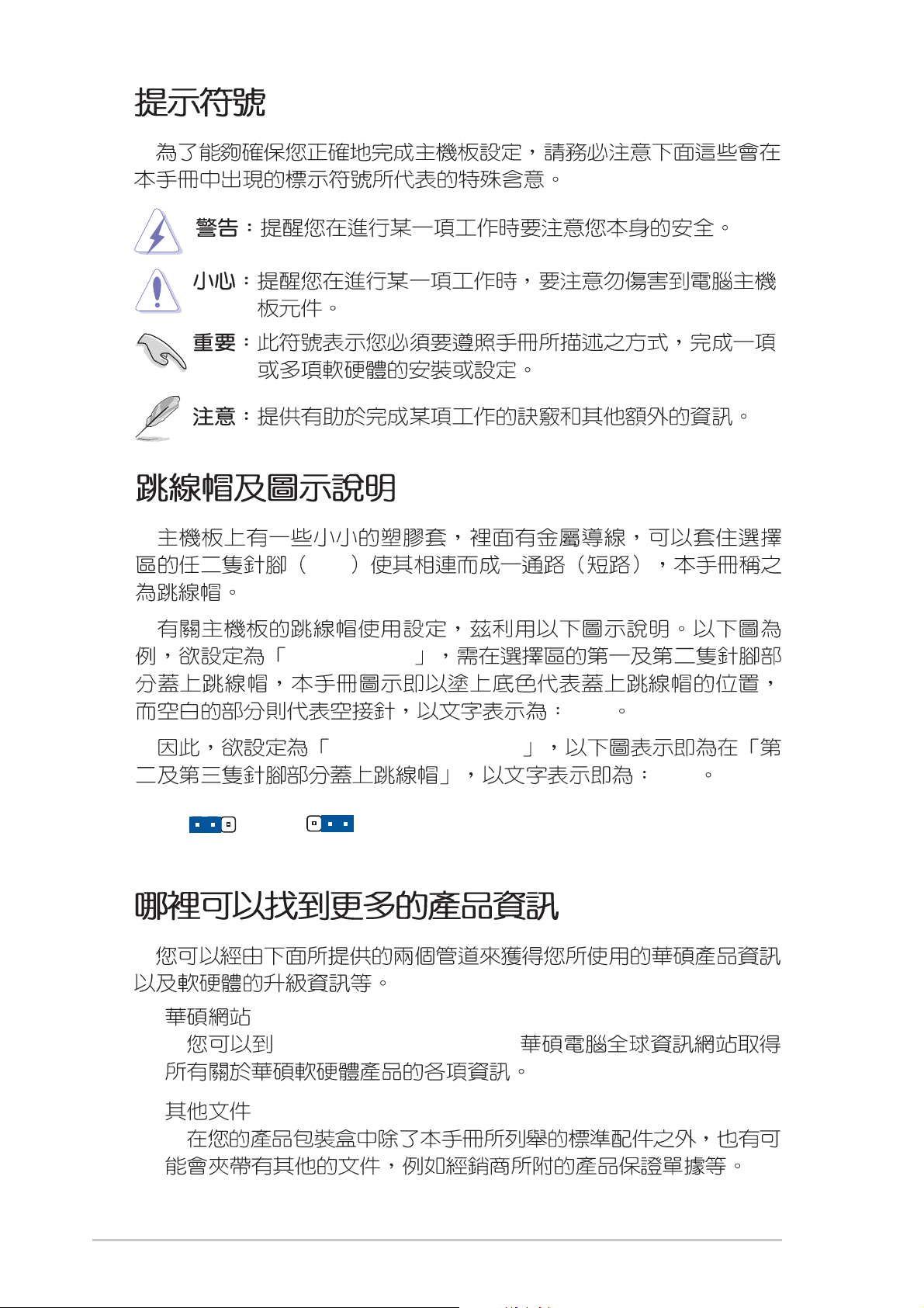
Pin
e
Jumper Mode
[1-2]
1.
2.
12
Jumper Mode
JumperFree
23
Jumper Fre
(Default)
™
Mode
http://www.asus.com.tw
[2-3]
iv
/
v
.......................................................................................................
iii
....................................................................................................................
..........................................................................................................
1.1
1.2
1.3
1.4
1.4.1
2.1 A7N266-VM
2.1.1
2.1.2
2.2
2.3
2.4
..................................................................................................................
..........................................................................................................................
..................................................................................................................
..............................................................................................................
A7N266-VM
....................................................................................................
A7N266-VM
........................................................................................................
CPU
.............................................................................................
v
vii
1
2
3
4
.........................................................
...............................................................................
....................................................................................
...........................................................................
5
7
7
7
8
10
11
2.5
2.6
2.7
2.8
3.1
2.4.1
2.4.2
............................................................................................................
2.5.1
2.5.2
2.5.3
................................................................................................................
2.6.1
2.6.2
2.6.3 PCI
2.6.4 AGP
............................................................................................................
............................................................................................................
..........................................................................................................
......................................................................................
..........................................................................................................
..............................................................................................
......................................................................................
..............................................................................................
..............................................................................................
...............................................................................
.....................................................................................
....................................................................................................
11
12
13
13
14
14
15
15
16
17
18
19
23
33
vi
3.2
................................................................................................................
34
BIOS
4.1 BIOS
4.1.1
4.1.2 BIOS
4.2 BIOS
4.2.1 BIOS
4.2.2
4.3
4.3.1 Primary&Secondary Master/Slave
4.3.2
4.4
4.4.1
4.4.2
4.4.3 PCI
4.5
4.5.1
4.5.2
Main Menu
......................................................................................................
Advanced Menu
/ I/O Device Configuration
PCI Configuration
Power Menu
..................................................................................
......................................................................
................................................................................
................................................................................
......................................................................................
..........................................................................................
................................................
Keyboard Features
..............................................................................
Chip Configuration
....................................................................................
Power Up Control
Hardware Monitor
.....................................................
........................................................
.................................
..............................................................
......................................................
.....................................................
35
35
37
39
40
40
42
43
47
49
52
54
56
59
61
62
4.6
4.7
5.1
5.2
5.3
5.4
5.5
5.6 3Deep Color Tuner
5.7 CyberLink PowerPlayer SE
5.8 CyberLink VideoLive Mail
6.1
BIOS Exit Menu
A7N266-VM
Boot Menu
........................................................................................................
....................................................................................................
..................................................................................................
................................................................................................................
.......................................................................................
................................................................................................
.....................................................................................
63
.............................................................................
.............................................................................
.........................................................................
....................................................................
65
67
67
67
74
79
80
82
83
85
vii
ASUSTeK COMPUTER INC.
150
886-2-2894-3447
886-2-2890-7798
info@asus.com.tw
0800-093-456 ... / / /
886-2-2890-7113 ...
886-2-2890-7114 ...
886-2-2890-7698
tsd@asus.com.tw
cscnews.asus.com.tw
www.asus.com.tw
ASUS COMPUTER INTERNATIONAL
6737 Mowry Avenue, Mowry Business Center,
Building 2 Newark, CA 94560, USA
+1-510-608-4555
tmdl@asus.com
+1-502-995-0883
+1-510-608-4555
+1-877-918-ASUS(2787)...
tsd@asus.com
www.asus.com
ASUS COMPUTER GmbH
Harkortstr. 25, 40880 Ratingen, BRD, Germany
49-2102-4420-66
sales@asuscom.de
49-2102-9599- 0 ... /
49-2102-9599-10 ...
49-2102-9599-11
www.asuscom.de/de/support
www.asuscom.de
viii
A7N266-VM
A7N266-VM
A7N266-VM
A7N266-VM
A7N266-VM
A7N266-VM
1.1
A7N266-VM AMD® Athlon
1GB DDR
AGP 4X
UltraDMA 100
A7N266-VM
A7N266-VM MicroATX 9.6 x 9.6
TM
XP AthlonTM DuronTM
USB/
40 IDE
3.5
COM2
I/O LAN
A7N266-VM
A7N266-VM
1
1.2
•
•
MX
A7N266-VM
®
AMD
Athlon™/ Athlon™ XP
Duron™ Socket A (462)
nVidia
®
220D GeForce
GPU 64bit DDR 1GB
266/200MHz DDR SDRAM 64bit 2.1GB
•
nVidia® nForce
MCP-D Media and Communications Processor
800MB/sec PCI USB
APU Audio Processing Unit
AC 97 UltraDMA 100/
66/33
100 MB/sec IDE
IDE USB PCI 2.2
PCI
• PC2100/PC1600 DDR
Date Rate
DIMM SDRAM
DDR Double
1GB DDR SDRAM
DDR SDRAM
•
UltraDMA/100 IDE IDE
IDE PIO
Mode 3
4 UltraDMA100/66/33 IDE
DVD-ROM CD-ROM CD-R/RW LS-120
TM
•
/
UART EPP ECP
UART2 COM2
PS/2 PS/2
•
AGP 4X USB PCI
SPDIF
•
PS/2 PS/2 2 USB
/ ATX
2
1.3
CPU ASIC
CPU
ACPI
Interface
PCI
PCI PCI PCI
ACPI Advanced Configuration and Power
OSPM OS Direct Power Management
BIOS
A7N266-VM
3
1.4 A7N266-VM
A7N266-VM
A7N266-VM
5
Socket A AMD Athlon™ XP/ Athlon
Duron
Realtek 8201L PHY
2Mbit
2 DDR DIMM 1GB
3 PCI
1
I/O 2 IDE
1
1
USB
1
1
1
1
1
USB
™
- /
AGP 4X
UltraDMA100/66
COM2
PS/2
PS/2
.......................................................
nVidia® nForce™220D ..........
nVidia® nForce™MCP-D
......................................
EEPROM
................................................
.......................................
.............................................................
.........................................................
..............................................
.................................................
Panel
Ports 2/3,4/5
........................................................
..........................................
............................................................
...................................
...................................
.............................................................
COM1
Ports 0,1
............................................
......................................
™/
.............
..................
......................
20
30
1
2
11
17
12
14
3
15
19
6
7
8
10
13
22
28
29
ASIC
LED
.........................................................................
........................................................................
......................................................
1
1
1
1
ATX
Micro-ATX
: www.asus.com
4
........................................
........................................
...........................................
.......................................................
........................................
.......................
9
5
18
17
16
26
25
24
4
2461
7
5
3
21 23 24
22
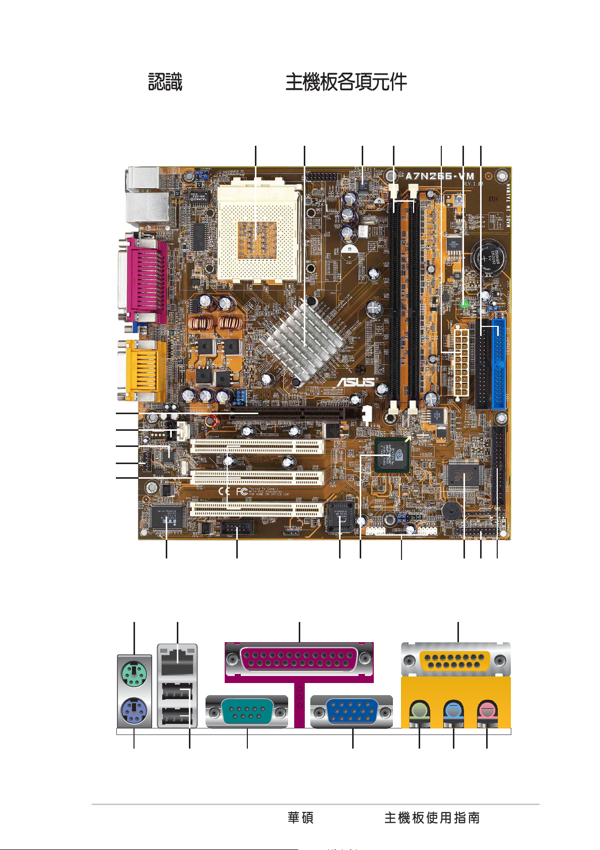
1.4.1 A7N266-VM
20
19
18
17
16
11
81013 12 91415
31 30
29 28 252627
A7N266-VM
5

6
2.1 A7N266-VM
VM
A7N266-VM MicroATX 24.5 9.6
x 24.5 9.6
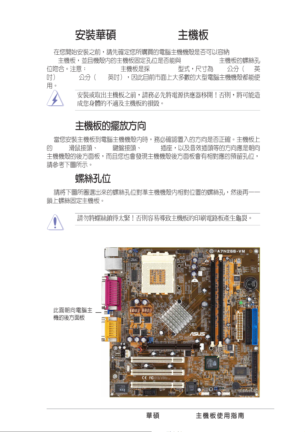
2.1.1
PS/2 PS/2 COM1
2.1.2
A7N266-
A7N266-VM
A7N266-VM
7
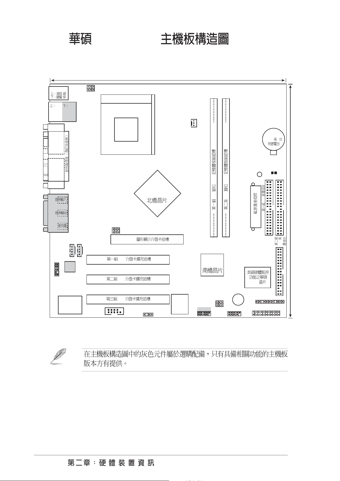
24.5cm (9.64in)
2.2 A7N266-VM
PS/2
( )
)
(
USB1
RJ-45
USB2
COM1
VGA
GAME_AUDIO
CD_IN1
USBPWR01
KBPWR1
BSEL0
BSEL1
AUDIO_COM1
Socket 462
AGP
nVidia
220D
CPU_FAN
A7N266-VM
DDR
DDR
184
184
0 1
2 3
PLED
ATX
CR2032
CMOS 3
CLRTC
IDE
Primary IDE
30.5cm (12.0in)
IDE
Audio
Codec
AAPANEL1
Super
I/O
COM2
PCI
PCI
PCI
SPDIF1
2Mb
BIOS
nVidia
MCP-D
USB45
USBPWR23
USBPWR45
BUZZER
USB23
ASIC
SMB
IDELED
Secondary IDE
FLOPPY
IR
PANEL
8
2.2.1
1) Socket 462 p.12 AMD
2) DIMM 1/2 p.14
3) PCI 1/2/3 p.18 32 PCI
4) AGP 4X p.18 AGP
1) BSEL0,BSEL1 p.19 CPU/DRAM
2) KBPWR p.20 +5V / +5VSB
4) USBPWR_01,_23,_45_ p.21 USB /
5) CLRTC p.22 CMOS
\ \
1) PS2KBMS p.23 PS/2 6 pin
2) PS2KBMS p.23 PS/2 6 pin
3) USB p.24 0,1 4-pin
4) COM1/COM2 p.24 9-pin/10-1 pin
5) VGA p.25 15-pin
6) PRINTER p.25 25-pin
7) GAME/AUDIO p.25 GAME/MIDI 15-pin
8) AUDIO p.26 1/8
9) IDELED p.26 IDE 2 pin
10) FLOPPY p.27 34-1 pin
11) PRIMARY IDE p.27 IDE 40-1 pin
SECONDARY IDE
12) CPU_FAN p.28 CPU
13) AAPANEL p.28
14) ATXPWR p.29 ATX
15) SMB p.29 SMBus 6-1 pin
16) CD_IN1,AUX p.30 4 pin
( 3 pin)
(10-1 pin)
20 pin
17) SPDIF1 p.30 (4-1 pin )
18) USB_23,_45 p.31 USB
19) IR p.31
20) PWR_LED (PANEL) p.32
21) KEYLOCK (PANEL) p.32
22) SPEAKER (PANEL) p.32
23) LED (PANEL) p.32
24) SMI (PANEL) p.32 SMI
25) PWR (PANEL) p.32 ATX
26) RESET (PANEL) p.32
( 10-1 pin)
( 5-1 pin)
(3-1 pin)
(2 pin)
(4 pin)
(2 pin)
(2 pin)
/ (2 pin)
(2 pin)
A7N266-VM
9
2.3
®
d
1.
2.
3.
4.
5. ATX
OFF
/
(LED) (1)
(2) (3)
A7N266-VM
A7N266-VM Onboard LED
ON
Standby
Power
PLED
OFF
Powere
Off
10
2.4 CPU
®
2.4.1
A7N266-VM AMD
Athlon
TM
XP/Athlon
Socket 462 Socket A A7N266-VM AMD
Athlon
384KB AMD 3DNow!TM Professional
TM
TM
XP QuantiSpeed
DuronTM
266MHz
A7N266-VM
CPU NOTCH
TO INNER
CORNER
LOCK
LEVER
A7N266-VM Socket 462
AMD™ CPU
CPU NOTCH
A7N266-VM
11
2.4.2
1. Socket A
90
2. Socket A
Socket 462
3. Socket A
Socket A
Socket A
4.
5.
Socket A
Socket A
CPU_FAN1
CPU_FAN1
Hardware monitoring errors
12
2.5
®
s
2.5.1
A7N266-VM 184 DDR DIMM Double Data Rate
unbuffered non-ECC 200/266 MHz
DDR DIMM 1 GB
A7N266-VM
A7N266-VM 184-Pin DDR
DIMM Sockets
104 Pin
80 Pins
DDR DIMM
PC-66 PC-100 PC-
133
SDR SDRAM
DDR SDRAM
CPU DDR SDRAM Double
Data Rate SDRAM
(SDR, Single Data Rate)
SDRAM
DDR SDRAM
100MHz 133MHz 166MHz
200MHz 266MHz 333MHz 100MHz DDR
SDRAM
GB/
166MHz DDR SDRAM 2.7 GB/
1.6 GB/ 133MHz DDR SDRAM 2.1
SDRAM
DDR
184 DDR DIMM 164 SDR DIMM
DDR DIMM SDR DIMM
DDR DIMM SDR DIMM
A7N266-VM
13
2.5.2
64, 128, 256, 512MB DDR DIMM
DIMM 184-pin DDR
Socket 1 (Rows 0&1) 64MB, 128MB, 256MB, 512MB x1
Socket 2 (Rows 2&3) 64MB, 128MB, 256MB, 512MB x1
( 1 GB) =
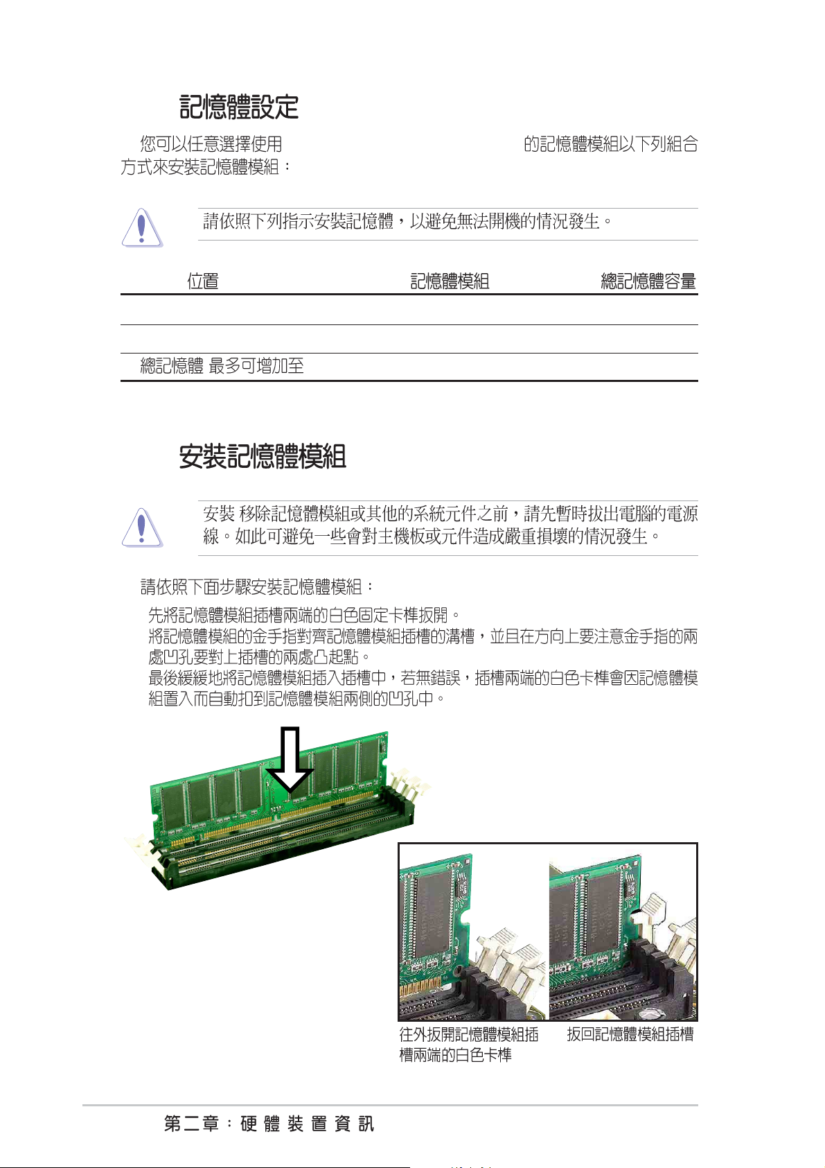
2.5.3
1.
2.
3.
/
14
2.6
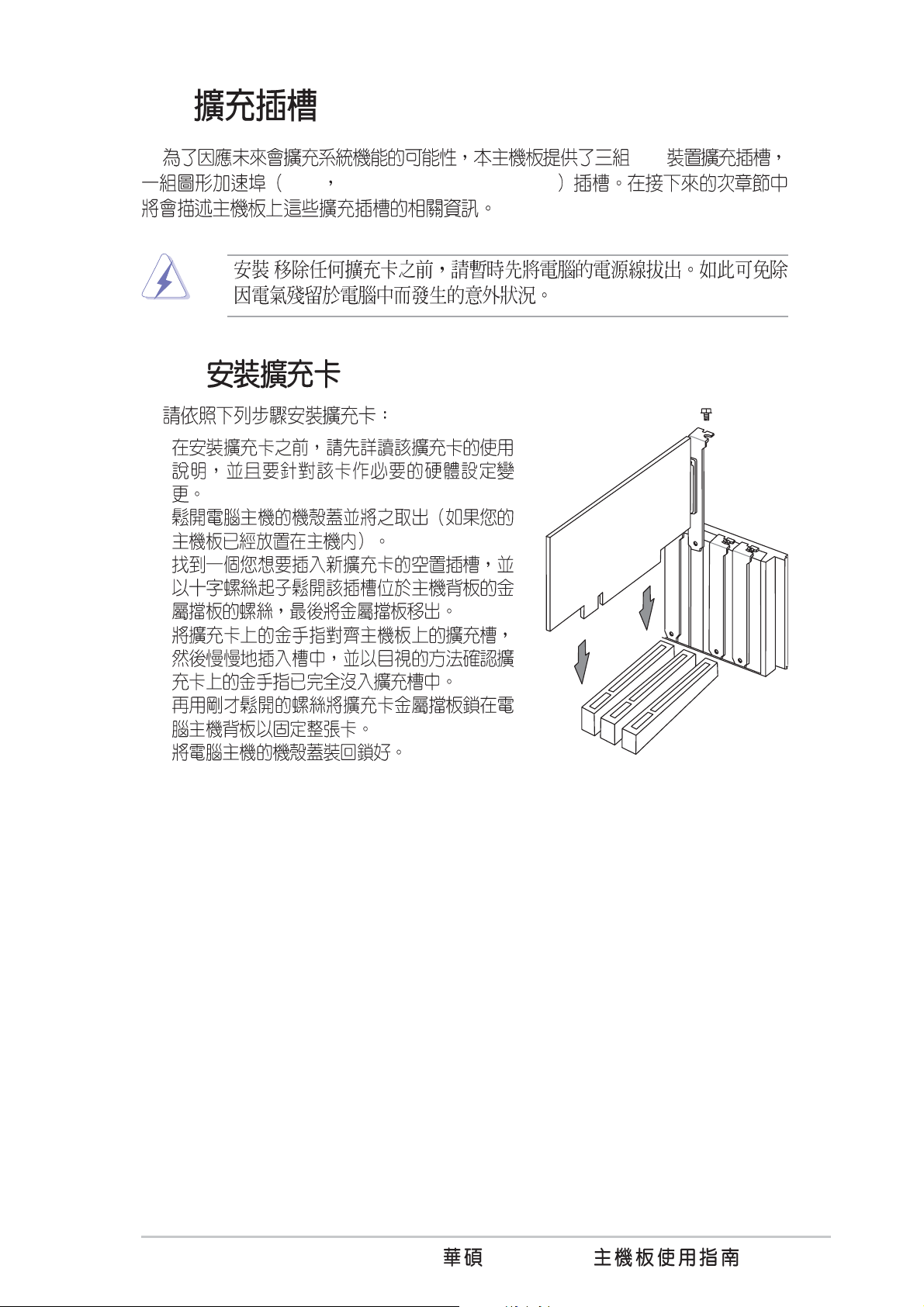
2.6.1
1.
2.
PCI
AGP Accelerated Graphics Port
/
3.
4.
5.
6.
A7N266-VM
15
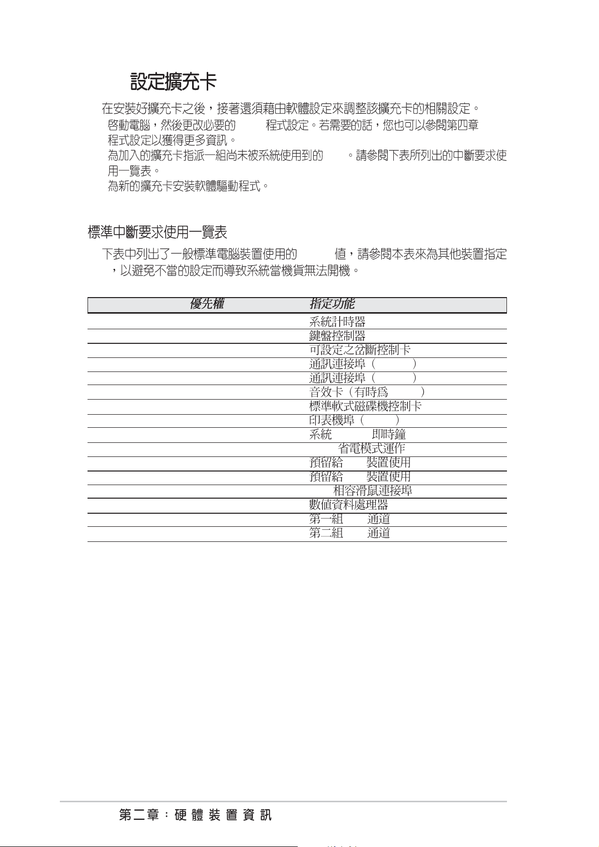
2.6.2
1. BIOS BIOS
2. IRQ
3.
IRQ
IRQ
IRQ
01
12
2 N/A
3* 11 COM 2
4* 12 COM 1
5* 13 LPT 2
614
7* 15 LPT 1
83 CMOS/
9* 4 ACPI
10* 5 PCI
11* 6 PCI
12* 7 PS/2
13 8
14* 9 IDE
15* 10 IDE
16
INT-A INT-B INT-C INT-DINT-E INT-F INT-G INT-H INT-I
PCI used --- --- --- --- --- --- --- -- PCI --- --- --- used --- --- --- --- ---
PCI --- --- used --- --- --- --- --- -- USB0 --- --- --- --- --- shared --- --- -- USB1 --- --- --- --- --- shared --- --- used
--- --- --- --- used --- --- --- ---
--- --- --- --- --- --- --- used ---
PCI
IRQ IRQ
IRQ
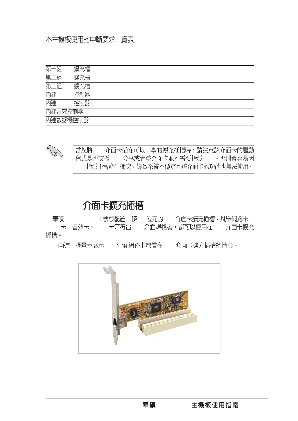
2.6.3 PCI
A7N266-VM 3 32 PCI
SCSI USB PCI PCI
PCI PCI
A7N266-VM
17
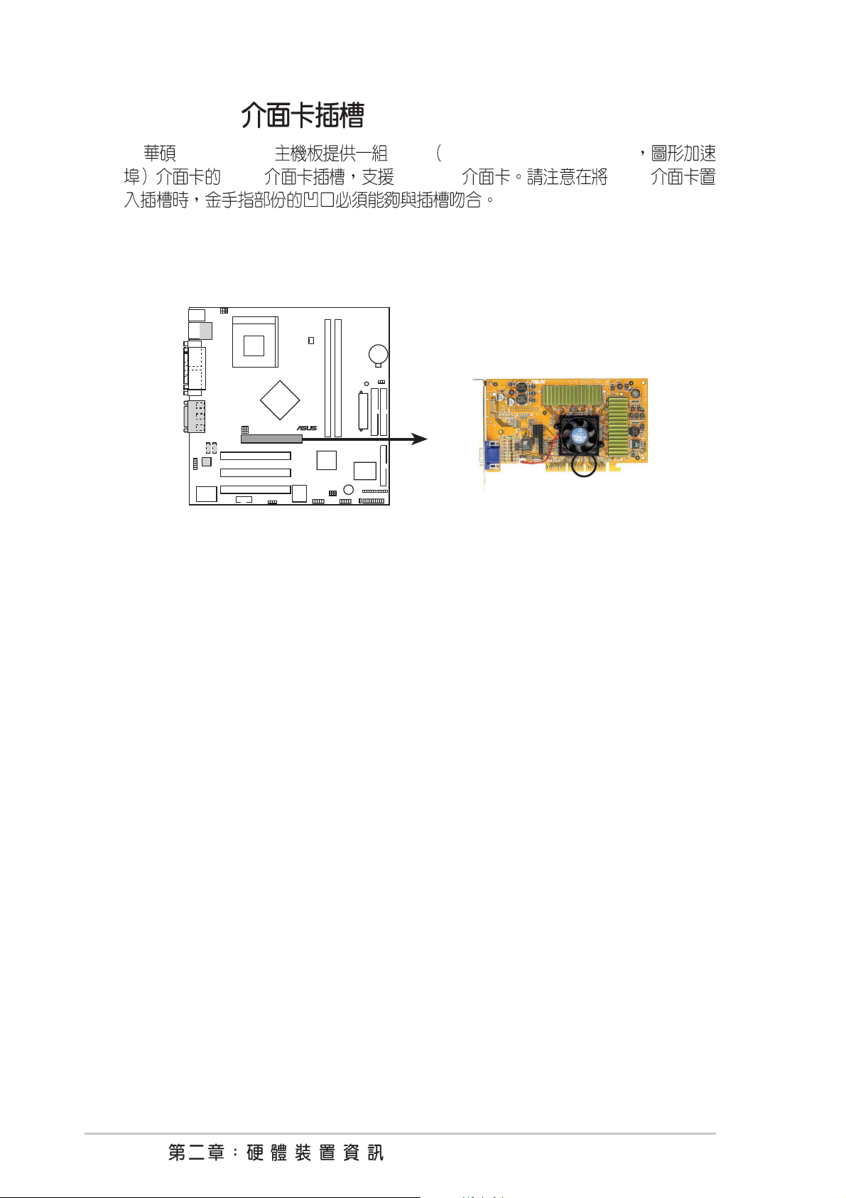
2.6.4 AGP
®
A7N266-VM AGP Accelerated Graphics Port
AGP AGP 4X AGP
A7N266-VM Accelerated Graphics Port (AGP)
A7N266-VM
Keyed for 1.5v
18
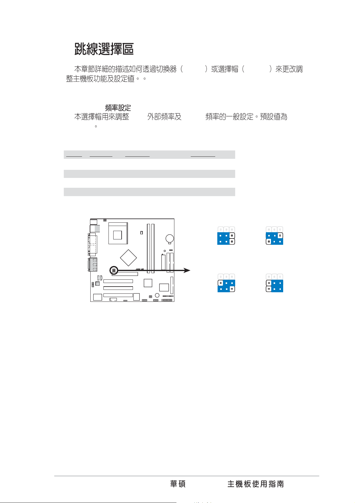
2.7
®
t)
Switch Jumper
1) CPU:DRAM (BSEL0, BSEL1)
CPU DRAM 133:
133 Mhz
CPU DRAM BSEL0 BSEL1
133 133 [1-2] (Default) [1-2] (Default)
100 100 [1-2] [2-3]
133 100 [2-3] [1-2]
100 133 [2-3] [2-3]
A7N266-VM
A7N266-VM CPU
External Frequency Selection
BSEL0
BSEL1
DRAM
CPU
BSEL0
BSEL1
DRAM
CPU
12
3
133MHz
100MHz
123123
100MHz
100MHz
BSEL0
BSEL1
DRAM
CPU
BSEL0
BSEL1
DRAM
CPU
123
100MHz
133MHz
133MHz
133MHz
(Defaul
A7N266-VM
19
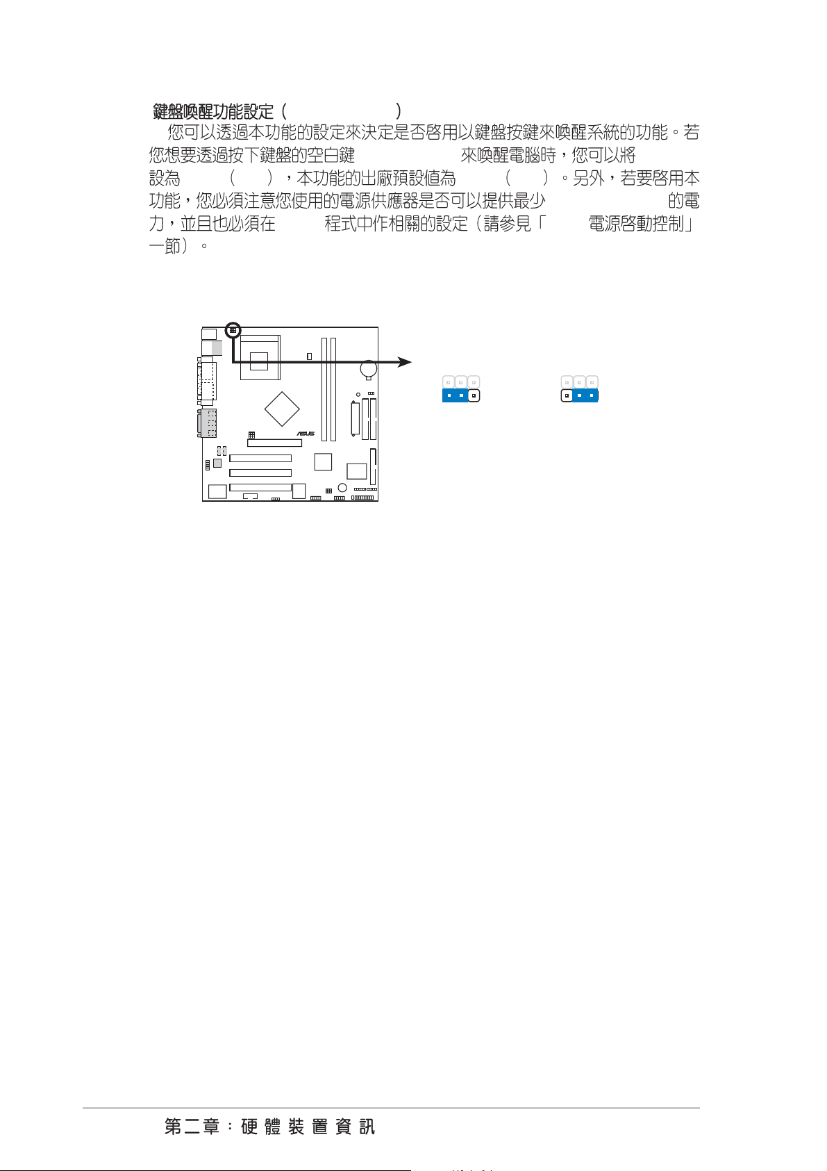
2) 3-pin KBPWR1
®
B
<Space Bar> KBPWR
[1-2] +5V [1-2] +5V
BIOS 4.5.1
720mA/+5VSB
A7N266-VM
A7N266-VM Keyboard Power Setting
2
1
+5V
(Default)
KBPWR1
2
+5VS
3
20

3) USB 2x3 pin USBPWR01,23,45
®
+5V USB S1 CPU
RAM
+5VSB USB S3
CPU RAM
+5VSB 2A/+5VSB
+5VSB +5V
+5VSB +5VSB
USBPWR01 USB USBPWR23
USB
A7N266-VM
A7N266-VM USB Device Wake Up
1. +5VSB
Enabled
2.
+5VSB
2
1
+5V
(Default)
12
+5V
(Default)
USBPWR01
USBPWR45
USBPWR23
2
+5VSB
23
+5VSB
3
A7N266-VM
21

4) CMOS CLRCMOS1
®
s
CMOS
1
2
3
4
5
6 <Del> BIOS
BIOS
A7N266-VM
CMOS
A7N266-VM Clear RTC RAM
CLR_CMOS
Short solder point
to Clear CMOS
22

2.8
1 PS/2 6-pin PS2KBMS
PS/2 IRQ12 PS/2
PS/2 BIOS
1
46
15
PS/2 Mouse (6-pin female)
2 PS/2 6-pin PS2KBMS
PS/2 mini DIN AT
large DIN PS/2
AT
PS/2 Keyboard (6-pin female)
A7N266-VM
23

3 USB0,1,2&3 4-pin USB
®
USB USB
Universal Serial Bus (USB)
4 9-pin COM1 / COM2
COM1 COM2
BIOS 4.4.2 /
USB
24
COM 1
Serial Port (9-pin male)
A7N266-VM
COM2
PIN 1
A7N266-VM Serial COM2 Bracket

5) ( 15-pin VGA)
VGA
VGA Monitor (15-pin female)
6 25-pin PRINTER
BIOS 4.4.2
Parallel (Printer) Port (25-pin female)
7) /MIDI 15-pin GAME_AUDIO
MIDI
Joystick/MIDI (15-pin female)
A7N266-VM
25

8 1/8
®
t
Line Out
Line In
Line Out Mic
Line Out Line In Mic
MicLine InLine Out
1/8" Stereo Audio Connectors
9 IDE 2 pin IDELED
IDE IDE
IDE IDE
A7N266-VM
TIP: If the case-mounted LED does no
light, try reversing the 2-pin plug.
A7N266-VM IDE Activity LED
IDE
IDELED
26

®
n
®
s
r
10 34-1 pin FLOPPY
A7N266-VM
A7N266-VM Floppy Disk Drive Connector
11 / IDE
(40-1 pin Primary IDE/Secondary IDE)
NOTE: Orient the red markings o
the floppy ribbon cable to
PIN 1
PIN 1
IDE IDE
IDE ( CD-ROM MO )
Primary Secondary
Master UltraDMA/100/66 IDE
Slave UltraDMA/100/66 IDE
Secondary BIOS
4.6
UltraDMA/100 UltraDMA/66 IDE 40- 80-
IDE 100MB/s 66MB/s
A7N266-VM
IDE
NOTE: Orient the red marking
Secondary IDE Connecto
A7N266-VM IDE Connectors
PIN 1
A7N266-VM
(usually zigzag) on the IDE
ribbon cable to PIN 1.
Primary IDE Connector
27

12 3 pin CPU_FAN
®
®
1
350mA 4.2 12
RPM Rotations Per Minute
CPU CPU
A7N266-VM
CPU_FAN
GND
+12V
Rotation
Rotation
A7N266-VM 12-Volt Cooling Fan Power
13) (10-1 pin AAPANEL)
A7N266-VM
MIC
MICPWR
LineOut_FR
NC
LineOut_FL
A7N266-VM Audio Panel Connector
AAPANEL
AGND
NC
LineOut_RR
LineOut_RL
28

14) (20-pin block ATXPWR)
®
®
ATX 12V
ATX 12V +5VSB
10
+5VSB 720mA
A7N266-VM
ATXPWR
A7N266-VM ATX Power Connector
15 SMBus 6-1 pin SMB
SMBus System Management Bus
A7N266-VM
+3.3VDC
-12.0VDC
COM
PS_ON#
COM
COM
COM
-5.0VDC
+5.0VDC
+5.0VDC
+3.3VDC
+3.3VDC
COM
+5.0VDC
COM
+5.0VDC
COM
PWR_OK
+5VSB
+12.0VDC
SMBus
SMB
1
+3V
Ground
A7N266-VM SMBus Connector
A7N266-VM
SMBCLK
FLOATING
SMBDATA
29

16) 4 pin CD_IN1,AUX
®
®
)
A7N266-VM
MPEG
A7N266-VM Internal Audio Connectors
17) 4-1 pin SPDIF1
S/PDIF /
/ /
A7N266-VM
Right Audio Channel
Ground
Left Audio Channel
CD_IN1
(Black)
AUX
(White
30
A7N266-VM Digital Audio Connector
SPDIF1
SPDIFOUT
+5V
GND

18) USB (10-1 pin USB23, USB45)
®
®
)
USB USB
USB 2 USB
USB
A7N266-VM
USB Power
USBP4–
USBP4+
GND
15
NC
USB23USB45
USB Power
USBP2–
USBP2+
GND
15
NC
610
USBP5–
USBP5+
USB Power
A7N266-VM Front Panel USB Headers
19 IrDA 5-1 pin IR
IrDA
IrDA
4.4.2 UART2 IrDA
SIR
CIR
610
GND
USBP3–
USB Power
GND
USBP3+
A7N266-VM
IR
+5V
GND
IRTX
IRRX
1
Front View Back View
IRTX
GND
IRRX
+5V
(NC
A7N266-VM Infrared Module Connector
A7N266-VM
31

20-pin PANEL)
®
A7N266-VM
Keyboard Lock
Power LED
Message LED
SMI Lead
A7N266-VM System Panel Connectors
* Requires an ATX power supply.
20 (3-1 pin PLED)
21 (2-pin KEYLOCK)
22 (4-pin SPEAKER)
PLED+
MLED+
PLED-
Keylock
MLED-
ExtSMI#
Speaker
Connector
Ground
Ground
+5V
GND
PWR
Ground
Reset SW
ATX Power
Switch*
Speaker
Ground
Reset
Ground
23 (2-pin LED)
24 SMI (2-pin SMI)
BIOS 4.5 Power Menu Suspend
Mode
ACPI
25 ATX / (2-pin PWR)
26 (2-pin RESET)
Turbo
Reset
32


3.1
1.
2.
3.
4. /
5.
a.
b. SCSI ( )
c.
6. ATX
ATX
30
Award BIOS
Award POST
CPU
7. Del BIOS
A7N266-VM
33

3.3
Windows95/98/2000/XP ATX
ATX
34

BIOS
BIOS
BIOS
BIOS

4.1 BIOS
4.1.1
AFLASH.
EXE
1. DOS FORMAT A:/S
2. DOS COPY D:\AFLASH\AFLASH.EXE A:\
BIOS BIOS
BIOS BIOS AFLASH.EXE
BIOS DOS
BIOS
AFLASH DOS Winodws MS-DOS
BIOS
AFLASH
AUTOEXEC.BAT
CONFIG.SYS
D AFLASH.EXE
3.
BIOS
4. DOS A:\AFLASH Enter AFLASH
Flash Memory unknown
ACPI BIOS
BIOS
A7N266-VM
35

5. 1. Save Current BIOS to File Enter
Save Current BIOS To File
6. A:\XXX-XX.
XXX
Enter
36
BIOS

4.1.2 BIOS
BIOS
BIOS BIOS
1. ( FTP BBS) BIOS
10
2.
3. A:\ AFLASH.EXE
4. MAIN MENU 2 Update BIOS Including Boot Block and
ESCD
5. Update BIOS Including Boot Block and ESCD
BIOS A:\XXX-XX.XXX
Enter
6. Y
A7N266-VM
37

7. AFLASH BIOS BIOS
Flashed Successfully
8. Esc
38
BIOS
BIOS
BIOS

4.2 BIOS
BIOS Basic Input and Output System
BIOS
BIOS
BIOS
RUN
SETUP
EEPROM Electrical Erasable Programmable Read-
Only Memory
BIOS BIOS BIOS
RAM
BIOS EEPROM
BIOS
BIOS
CMOS
BIOS
POST Power-On Self Test
DELETE DELETE
RESET ALT - CTRL - DEL
BIOS
BIOS
A7N266-VM
39

4.2.1 BIOS
BIOS
MAIN
ADVANCED BIOS
POWER
BOOT
EXIT BIOS
4.2.2
BIOS
<F1> or <Alt + H>
<Esc> or<Alt + X>
or → (keypad arrow)
←
or ↓ (keypad arrows)
↑
- (minus key)
+ (plus key) or spacebar
<Enter>
<Home> or <PgUp>
<End> or <PgDn>
<F5>
<F10>
Exit
BIOS
40
BIOS

F1 Alt + H
BIOS
BIOS
PgUp PgDn
Home End
Enter Esc
Enter
ESC
BIOS
BIOS
BIOS F5
Specific Help
BIOS
Item
A7N266-VM
41

4.3 Main Menu
BIOS
System Time [XX:XX:XX]
00 23 00 59 00 59 Tab Tab +
Shift
System Date [XX/XX/XXXX]
1
12 1 31 00 99 Tab Tab + Shift
Legacy Diskette A [1.44M, 3.5 in.]
[None][360K 5.25 in.] [1.
5.25 in.] [720K 3.5 in.] [1.44M 3.5 in,] [2.88M 3.5 in.]
2M
Floppy 3 Mode Support [Disabled]
1.2MB 3.5
[Disabled] [Enabled]
42
BIOS

4.3.1 Primary & Secondary Master/Slave
Type [Auto]
[Auto] IDE
BIOS
[User Type HDD]
IDE
A7N266-VM
43

[User Type HDD]
Sector
Cylinder Head
Main
BIOS
FDISK
FDISK
active
[None]
- IDE
- LS-120
- ZIP
- IDE
- IDE
Esc
44
BIOS

Translation Method [LBA]
IDE LBA Logical
Block Access
[LBA] [LARGE] [Normal] [Match Partition Table] [Manual]
28
Cylinders
Cylinder
[Manual]
Head
/
[Manual]
Sector
[Manual]
504MB LBA
[User Type HDD]
[User Type HDD]
Sector
[User Type HDD]
CHS Capacity
CHS CHS
C X H X S
Maximum LBA Capacity
LBA
528MB BIOS LBA
Multi-Sector Transfers [Maximum]
[User Type HDD] : [Disabled] [2 Sectors] [4 Sectors] [8
Sectors] [16 Sectors] [32 Sectors] [Maximum]
A7N266-VM
45

SMART Monitoring [Disabled]
S.M.A.R.T. Self-
Monitoring, Analysis and Reporting Technology
[Disabled]
[Enabled]
PIO Mode [4]
/ PIO Programmed Input/
Output
Mode 4 [0] [1] [2] [3] [4]
IDE Mode 0
Ultra DMA Mode [Disabled]
Ultra DMA IDE
[Disabled] Ultra DMA [Type] [User
Type HDD]
[0] [1] [2] [3] [4] [5] [Disabled]
46
BIOS

4.3.2 Keyboard Features
Boot Up NumLock Status [On]
[Off] [On]
Keyboard Auto-Repeat Rate [12/Sec]
Sec] [15/Sec] [20/Sec] [24/Sec] [30/Sec]
Keyboard Auto-Repeat Delay [1/4 Sec]
[3/4 Sec] [1 Sec]
Number Lock
[6/Sec] [8/Sec] [10/Sec] [12/
[1/4 Sec] [1/2 Sec]
A7N266-VM
47

Language [English]
BIOS
Supervisor Password [Disabled] / User Password [Disabled]
Enter
Enter 8
Enter
Enter
BIOS
Enter
Enter
BIOS BIOS
BIOS Supervisor
password
Supervisor BIOS
User password
BIOS
?
CMOS RTC
2.7 RTC
Halt On [All Errors]
[All Errors] [No Error] [All but Keyboard] [All but Disk] [All but Disk/Key]
Installed Memory [XXX MB]
48
BIOS

4.4 Advanced Menu
CPU Speed [Manual]
JumperFreeTM
[Manual]
CPU/PCI Frequency (MHz)[100/33]
PCI
PCI PCI
CPU Frequency
Multiple
CPU/Memory Frequency Ratio [Auto]
CPU Frequency(MHz [Auto]
[1:1] [3:4][3:5]
CPU
CPU Level 1 Cache, CPU Level 2 Cache [Enabled]
CPU [Disabled]
[Enabled]
CPU Level 2 Cache ECC Check [Enabled]
[Disabled] [Enabled]
A7N266-VM
ECC
49

CPU Fast Decode [Disabled]
CPU
[Enabled] [Disabled]
BIOS Update [Enabled]
BIOS CPU
BIOS CPU [Disabled]
[Enabled]
PS/2 Mouse Function Control [Auto]
[Auto] PS/2
BIOS IRQ 12 PS/2 IRQ 12
[Enabled] PS/2 BIOS
IRQ 12 PS/2 [Enabled] [Auto]
USB Legacy Keyboard Support [Disabled]
USB [Disabled]
USB [Primary]
[Secondary] USB01 USB23 USB45 USB
[Disabled] [Primary] USB [Disabled]
[Primary] [Secondary][USB Floppy Zip]
OS/2 Onboard Memory > 64M [Disabled]
OS/2 64MB
[Enabled] [Disabled] [Disabled]
[Enabled]
50
BIOS

Jumperless
CPU
CPU CPU
100MHz BIOS
1.
CMOS CMOS
CMOS RTC ( 22 59 )
2.
CPU
CPU Upgrade/Reinstallation
100MHz
BIOS
BIOS
BIOS
CPU
3. CPU 1
CPU
4. CPU 2
CPU
CPU
CPU
CPU
A7N266-VM
51

4.4.1 Chip Configuration
SDRAM Configuration [By SPD]
2 5
[By SPD] SPD (Serial Presence Detect) 2
5 EEPROM
memory type size speed voltage module
banks
SDRAM Configuration [User Define]
[User Define][7ns(143MHz)][8ns(125MHz)][By SPD]
SDRAM CAS Delay [Auto (Normal)]
SDRAM /
[Auto (Normal)] [2.0T (Normal)] [2.5T (Normal)] [Auto
(TURBO)] [2.0T (TURBO)] [2.5T (TURBO)]
Clock Spread Spectrum Mode [Center Spread]
[Center Spread] [Spread Down] [Disabled]
VGA Shared Memory Size [32MB]
VGA [8MB] [16MB]
[32MB]
Graphics Aperture Size [64MB]
AGP [32MB]
[64MB] [128MB] [256MB] [512MB]
52
BIOS

Internal Graphic Over-clocking [Disable]
[Disable] [Enable]
Internal VGA LCD TV Display Type [NTSC-M]
[NTSC-M]
[NTSC-J] [PAL-M] [PAL-BDGHI]
[PAL-N] [PAL-NC]
Video Memory Cache Mode [UC]
USWC uncacheable, speculative write combining
UC uncacheable [UC] [USWC]
Onboard VGA BIOS Update [Enabled]
[Enabled] [Disabled]
MCP IDE Controller [Both]
[Both] [Primary] [Secondary] [Disabled]
MCP USB Controller [Enabled]
USB USB Legacy
Keyboard support
[Enabled] [Disabled]
MCP Audio Controller [Auto]
[Disabled] [Auto]
MCP MAC Controller [Enabled]
[Disabled] [Enabled]
MCP DOLBY DIGITAL Controller [Auto]
MCP-D [Disabled] [Auto]
PCI 2.1 Support [Enabled]
[Disabled] [Enabled]
USB
A7N266-VM
53

4.4.2 / I/O Device Configuration
Onboard FDC Swap A & B [No Swap]
Floppy Disk Access Control [R/W]
[Read Only]
[R/W] /
[R/W] [Read Only]
Onboard Serial Port 1 [3F8H/IRQ4]
Onboard Serial Port 2 [2F8H/IRQ3]
COM 1 COM 2 COM 1 COM 2
[3F8H/IRQ4] [2F8H/IRQ3] [3E8H/IRQ4] [2E8H/IRQ10]
[Disabled]
UART2 Use Standard Infrared [Disabled]
COM 2 COM 2
[Disabled] [Enabled]
Onboard Parallel Port [378H/IRQ7]
[No Swap] [Swap AB]
SIR
Port Mode
IRQ7] [278H/IRQ5]
ECP DMA Select [Disabled] [378H/
54
Parallel
BIOS

Parallel Port Mode [ECP+EPP]
[Normal] [EPP]
[ECP] [ECP+EPP]
Two-way
ECP ECP DMA
[ECP] [ECP+EPP]
ECP DMA Select [3]
ECP DMA Parallel Port Mode
[ECP] [ECP+EPP] [1] [3]
[Disabled]
Onboard Game Port [200H-207H]
Game Port I/O [200H-207H] [208H-20FH]
[Disabled]
Onboard MIDI [Disabled]
ECP
[Normal] [EPP]
[Disabled]
MIDI I/O [330H-331H] [300H-301H]
A7N266-VM
55

4.4.3 PCI PCI Configuration
Slot 1, Slot 2, Slot 3 [Auto]
PCI IRQ
[Auto] IRQ [Auto] [NA] [3] [4] [5]
[7] [9] [10] [11] [12] [14] [15]
PCI/VGA Palette Snoop [Disabled]
MPEG
[Enabled]
VGA [Disabled] [Disabled]
[Enabled]
PCI Latency Timer [32]
[32]
Primary VGA BIOS [AGP VGA Card]
PCI AGP
[PCI VGA Card] [AGP VGA Card]
[Onboard VGA]
56
BIOS

PCI DMA
DMA x Reserved for Legacy Drive [No/ICU]
DMA PNP ISA [No/
ICU]
DMA ICU DMA [Yes]
[No/ICU] [Yes]
DMA ICU ISA
PCI UMB
TSM MEM Block BASE [No/ICU]
PnP ISA
C800 DFFF ISA ICU
MEM Block Size
ICU TSM MEM Block BASE
[No/ICU] [No/ICU] [C800] [CC00] [D000] [D400] [D800] [DC00]
A7N266-VM
57

4.4.5 Shadow Configuration
Video ROM BIOS Shadow [Enabled]
VIDEO BIOS ROM RAM
[Disabled] [Enabled]
C8000-DFFFF Shadow [Disabled]
ROM RAM
ROM
640K 1024K [Disabled] [Enabled]
58
BIOS

4.5 Power Menu
ACPI Suspend To RAM [Disabled]
ACPI Suspend-to-RAM
720mA/ +5VSB [Disabled] [Enabled]
Video Off Option [Suspend -> Off ]
[Always On] [Suspend -> Off]
Video Off Method [DPMS OFF]
DPMS OFF DPMS
Reduce ON
Suspend
DPMS [Blank Screen]
Blank Screen
[Blank Screen] [V/H SYNC+Blank] [DPMS Standby] [DPMS Suspend] [DPMS OFF]
[DPMS Reduce ON]
Blank Screen V/H SYNC + Blank DPMS Standby DPMS
DPMS (Display Power Management System) BIOS
[V/H SYNC+Blank]
DPMS BIOS GREEN
HDD Power Down [Disabled]
[Disable] [1 Min] [2 Min] [3 Min]...[15 Min]
A7N266-VM
59

PWR Button < 4 Secs [Soft off]
Soft Off ATX ATX
Suspend ATX
ATX
[Soft off] [Suspend]
60
BIOS

4.5.1 Power Up Control
AC PWR Loss Restart [Disabled]
[Previous State]
[Disabled] [Enabled] [Previous State]
Power Up On PCI Card [Disabled]
[Enabled] PCI
ATX 1 5VSB
Disabled] [Enabled]
Power On By PS/2 Keyboard [Disabled]
1 5VSB
[Space Bar] [Ctrl-Esc] [Power Key]
Power On By PS/2 Mouse [Disabled]
1 5VSB
[Disabled]
ATX
[Disabled]
ATX
[Enabled]
A7N266-VM
[Disabled]
61

4.5.2 Hardware Monitor
MB Temperature [xxxC/xxxF]
CPU Temperature [xxxC/xxxF]
PWRTMP BIOS
2-32 PWRTMP Power Temperature
[N/A]
CPU Fan Speed [xxxxRPM]
RPM Rotations Per Minute
VCORE Voltage, +3.3V Voltage, +5V Voltage, +12V Voltage
CPU
62
error. Enter Power setup menu for details
F1 to continue, DEL to enter SETUP
BIOS
: Hardware Monitor found an
: Press
F1 DEL

4.6 Boot Menu
Space
[Removable Devices] [IDE Hard Drive] [ATAPI CD-
ROM] [Other Boot Device]
Removable Device [Legacy Floppy]
[Disabled] [Legacy
Floppy] [LS-120] [ZIP] [ATAPI MO]
IDE Hard Drive
IDE [Enter]
IDE
ATAPI CD-ROM
ATAPI IDE
[Enter] ATAPI
Other Boot Device Select [INT18 Device (Network)]
[Disabled] [SCSI Boot Device] [INT18 Device(Network)]
A7N266-VM
63

Boot Virus Detection [Enabled]
BIOS
[Disabled] [Enabled]
Quick Power On Self Test [Enabled]
POST POST
[Disabled][Enabled]
Boot Up Floppy Seek [Enabled]
BIOS 40
80 [Disabled] [Enabled]
BIOS
Interrupt Mode [APIC]
16 [PIC][APIC]
APIC Advanced Programmed Interrupt Controller
16
64
BIOS

4.7 BIOS Exit Menu
Exit BIOS
BIOS
Esc
Exit Saving Changes
BIOS CMOS
Enter Yes
CMOS BIOS No BIOS
BIOS BIOS
Enter
BIOS
Exit Discarding Changes
BIOS
Enter Yes CMOS
BIOS No BIOS
A7N266-VM
65

Load Setup Defaults
F5 Enter
Yes BIOS No
BIOS
Discard Changes
BIOS
Enter Yes
BIOS No BIOS
Save Changes
BIOS
Enter Yes
BIOS No BIOS
66
BIOS


5.1
Microsoft Windows 98/ME/NT/2000/XP IBM OS/2
OS Operating System
5.1.1 Windows 98
Windows
Windows Windows
Windows
5.2
5.2.1
http://www.asus.com.tw
A7N266-VM
67

5.3 A7N266-VM
D
5.3.1 Main menu
D:\ASSETUP.EXE
NVIDIA nForce
•
NVIDIA
•
98
Audio Hotfix
•
Microsoft Direct X
•
•
BIOS
Microsoft DirectX 8.1
•
PC-cillin 2000
•
ADOBE Acrobat Reader
•
Windows ME
INF )
NVIDIA Windows
ASUS Live Update
Microsoft DirectX 8.0a
PC-cillin
Adobe Acrobat PDF
Windows NT (
Audio Hotfix
68
www.asus.com

•
•
•
Cyberlink Cyberlink PowerPlayer SE
VideoLive Mail
E-Color 3Deep
CRT
LCD
•
•
•
•
5.3.2
BIOS
CPU
A7N266-VM
69

5.3.3 Windows 98
nVidia
Win98 nVidia
1. PCI System Management Bus
2. PCI Standard Host CPU Bridge
3. PCI Standard RAM Controller
®
®
PCI System Management Bus
1.
2. PCI System Management Bus
3.
4.
5.
6.
7.
D D :\Drivers\Chipset\Nvidia\win9x\SMbus
8.
9. PCI System Management
10.
11.
PCI Standard Host CPU Bridge (GART driver)
1.
2. PCI standard Host CPU Bridge
3.
4.
5.
6.
7.
D D :\Drivers\Chipset\Nvidia\win9x\Gart
8.
9. AGP Host to the PCI Bridge
10.
11.
70

PCI Standard Ram Controller
1.
2. PCI standard RAM Controller
3.
4.
5.
6.
7.
D D :
\Drivers\Chipset\Nvidia\win9x\MemoryController
8.
9. NVIDIA nForce 220D Memory Controller NVIDIA nForce 420
Memory Controller
10.
DDR
5.3.4 Windows 98
Nvidia
1.
2.
3. windows
4.
5. USB
6. CD-ROM
: Drivers Chipset Nvidia 103 win9XME
7.
Processing unit(Dolby Digital)
8.
NVIDIA Codec Interface nForce MCP Audio
A7N266-VM
71

5.3.5 NVIDIA MCP MAC Win98
1.
2. -
3.
4.
5.
6.
7.
D D :\Drivers\Chipset\Nvidia\103\win9xme
8.
9. NVIDIA nForce MCP networking Adaptor
10.
11.
5.3.6 NVIDIA GeForce2 GPU Win98
1.
2. Standard PCI Graphics Adapter(VGA)
3.
4.
5.
6.
7.
D D :\Drivers\Chipset\Nvidia\103\ win9xme
8.
9. NVIDIA GeForce2 Integrated GPU
10.
11.
72

A7N266-VM
73

5.4
5.4.1
CPU
ASUS Utility\Probe Vx.xx Vx.xx
Tray
74

5.4.2
CPU
CPU
CPU
A7N266-VM
75

CPU
CPU CPU
CPU
76
FAT

CPU CPU
A7N266-VM
77

5.4.3
CPU !!!
78

5.5
1. / /
AsusUpdate Vx.xx.xx
ASUSUpdate
Vx.xx.x
2.
Next
BIOS
ISP
3. /
FTP
Auto
Select
4. BIOS
Next
5. BIOS
Next
BIOS
BIOS
A7N266-VM
79

5.6 3Deep Color Tuner
3Deep color tuner 3D
3Deep color tuner
3Deep color tuner
5.6.1 3Deep
1.
2.
3.
80

4.
5.
6.
True Internet Color
True Internet Color
Setup
5.6.2 3Deep
3Deep - -
3Deep - 3Deep Control Panel
3Deep
3Deep gamma Set Game
Gamma
Run Color Wizard ?
3Deep
A7N266-VM
81

5.7 CyberLink PowerPlayer SE
CyberLink PowerPlayer SE
CD MP3
5.7.1 CyberLink PowerPlayer SE
CyberLink PowerPlayer / /CyberLink
PowerPlayer SE
5.7.2 CyberLink PowerPlayer
PowerPlayer
i-Power!
82
OK

5.8 CyberLink VideoLive Mail
CyberLink VideoLive Mail Plus 3.0 ( VLM 3)
VLM3 VLM 3
VLM 3
AVI
Internet
VLM 3 1:900 30 VLM 3 CIF
(352 x 288 pixel)
500KB
VLM 3 Video for Windows Video for Windows
QCIF (176 x 144)
A7N266-VM
83

5.8.1 VideoLive Mail
VideoLive Mail CyberLink
VideoLive Mail
1.
2.
3. (1/2)
4. (2/2)
MAPI
5.
VideoLive Mail x.x VLM3
MAPI
VideoLive Mail
6. (1/3) GSM CODEC
7. (2/3) (3/3)
8.
5.8.2 VideoLive Mail
84
 Loading...