

Page 1

®
A7N266
JumperFree
266MHz
®
NVIDIA
nForce 420
Socket A
DDR DRAM
™
™
Page 2
Intel Pentium Intel
VIA
3Com 3Com
C-Media
Windows MS-DOS
Adobe Acrobat Adobe System
Trend ChipAwayVirus
Symbios Symbios Logic
nVidia NVIDIA
BIOS
1.22 1.24 ...
©
2001
: A7N266
: 1.00 T853
: 2001 12
2
A7N266
Page 3
150
886-2-2894-3447
886-2-2890-7798
info@asus.com.tw
0800-093-456
886-2-2890-7111 ... /
886-2-2890-7112 ...
886-2-2890-7113 ... /
886-2-2890-7698
tsd@asus.com.tw
cscnews.asus.com.tw
http://www.asus.com.tw/
ASUS COMPUTER INTERNATIONAL ( )
6737 Mowry Avenue, Mowry Business Center, Building 2
Newark, CA 94560, USA
+1-510-608-4555
tmdl@asus.com
+1-510-608-4555
+1-877-918-ASUS(2787)...
tsd@asus.com
www.asus.com
ASUS COMPUTER GmbH ( )
Harkortstr. 25, 40880 Ratingen, BRD, Germany
49-2102-4420-66
sales@asuscom.de
49-2102-9599-0 ... /
49-2102-9599-10 ..
49-2102-9599-11
www.asuscom.de/de/support
www.asuscom.de
A7N266
3
Page 4
1.1
...........................................................................
7
1.2
2.1 A7N266
2.1.1
2.1.2
2.1.3
2.2
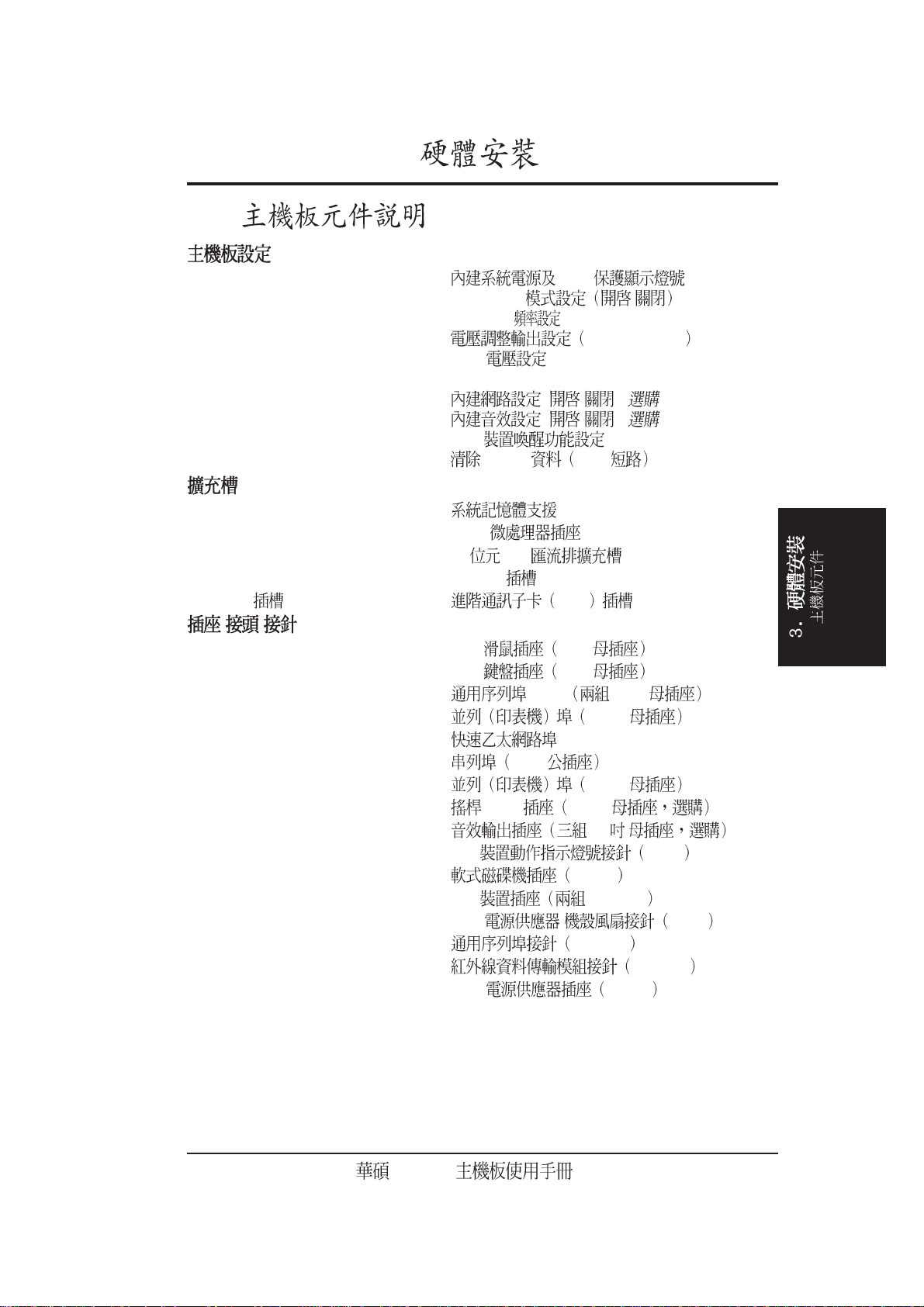
3.
3.1
3.2
3.3
.......................................................................................
........................................................
.....................................................................................................
.....................................................................................................
...................................................................................................
..............................................................................
..........................................................................................
......................................................................................
..........................................................................................
7
8
8
9
10
12
14
15
16
3.4
3.5
3.5.1 DDR DIMM
3.5.2
3.5.3
..............................................................................................
...................................................................................................
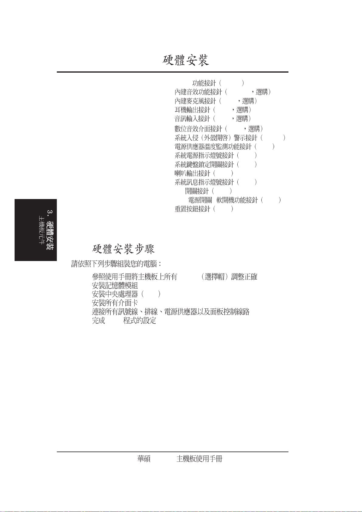
3.6 CPU
3.7
3.7.1
3.7.2
3.7.3
3.7.4 AGP Pro
3.8
3.9
......................................................................................................
..............................................................................................
..................................................................................................
..............................................................................
17
23
.....................................................................................
.......................................................................................
..............................................................................
23
24
25
26
27
.......................................................................................
IRQ
ACR
..........................................................
...............................................................
...............................................................
27
28
29
30
31
45
4
A7N266
Page 5

4.BIOS
4.1 BIOS
4.1.1
4.1.2 BIOS
4.2 BIOS
4.2.1 BIOS
4.2.2
................................................................................................
4.3 Main Menu
4.3.1 Primary & Secondary Master/Slave
4.3.2
4.4 Advanced Menu
4.4.1 Chip Configuration
4.4.2 I/O Device Configuration
4.4.3 PCI Configuration
4.4.4 Shadow Configuration
4.5 Power Menu
................................................................................
.............................................................................................
.........................................................................................
.......................................................................................
...............................................................................
...........................................................................................
...................................................................
PCI
.........................................................................
47
.......................................................................
47
49
51
52
52
54
..........................................
55
58
60
....................................................
I/O
..................................................................
...........................................................
................................................
63
65
67
69
70
4.5.1 Power Up Control/
4.5.2 Hardware Monitor/
4.6 Boot Menu/
4.7 Exit Menu
5.
5.1
5.2
Windows
5.3
5.3.1
5.3.2
5.3.3 Windows 98
6.
.............................................................
............................................................
...............................................................................
.....................................................................................
..................................................................................................
....................................................................
A7N266
...............................................................................
...................................................................................................
......................................................
......................................................
71
72
73
75
77
77
78
78
79
80
6.1
..................................................................................
82
A7N266
5
Page 6
6.2
......................................................................................
83
6.2.1
6.2.2
6.2.3
6.3
6.3.1 C-Media
6.3.2 C-Media
6.3.3
6.4 3Deep Color Tuner
6.4.1 3Deep
6.4.2 3Deep
/
...................................................................................
...............................................................................
...............................................................................
..............................................................................
........................................................................................
..........................................................................
........................................................................................
........................................................................................
6.5 CyberLink PowerPlayer SE
6.5.1 CyberLink PowerPlayer SE
6.5.2 CyberLink PowerPlayer
6.6 CyberLink VideoLive Mail
6.6.1 VideoLive Mail
......................................................................
83
84
...................................................................
87
88
88
................................................................
88
89
90
90
91
....................................................
.......................................................
...........................................................
92
92
92
93
.........................................................................
94
7.
6.6.2 VideoLive Mail
7.1
7.2
7.1.1 /
7.1.2
7.1.3
..................................................................................................
56K
Windows 98
.....................................................................
94
95
.....................................................................
......................................................................
...............................................................................
...........................................................
99
99
99
100
6
A7N266
Page 7
1.1
1.2
<1>
<2>
<3>
<4> BIOS
<5>
<6>
<7>
1.
BIOS
(1)
(1) 40 80 UltraDMA/100/66/33 IDE
(1) 40 80
(1)
(1) USB
(1)
(1)
(1) COM 2
(1) S/PDIF ( )
(1) ( )
(2) ( )
(1)
AGP-DVI/TV
A7N266
7
Page 8
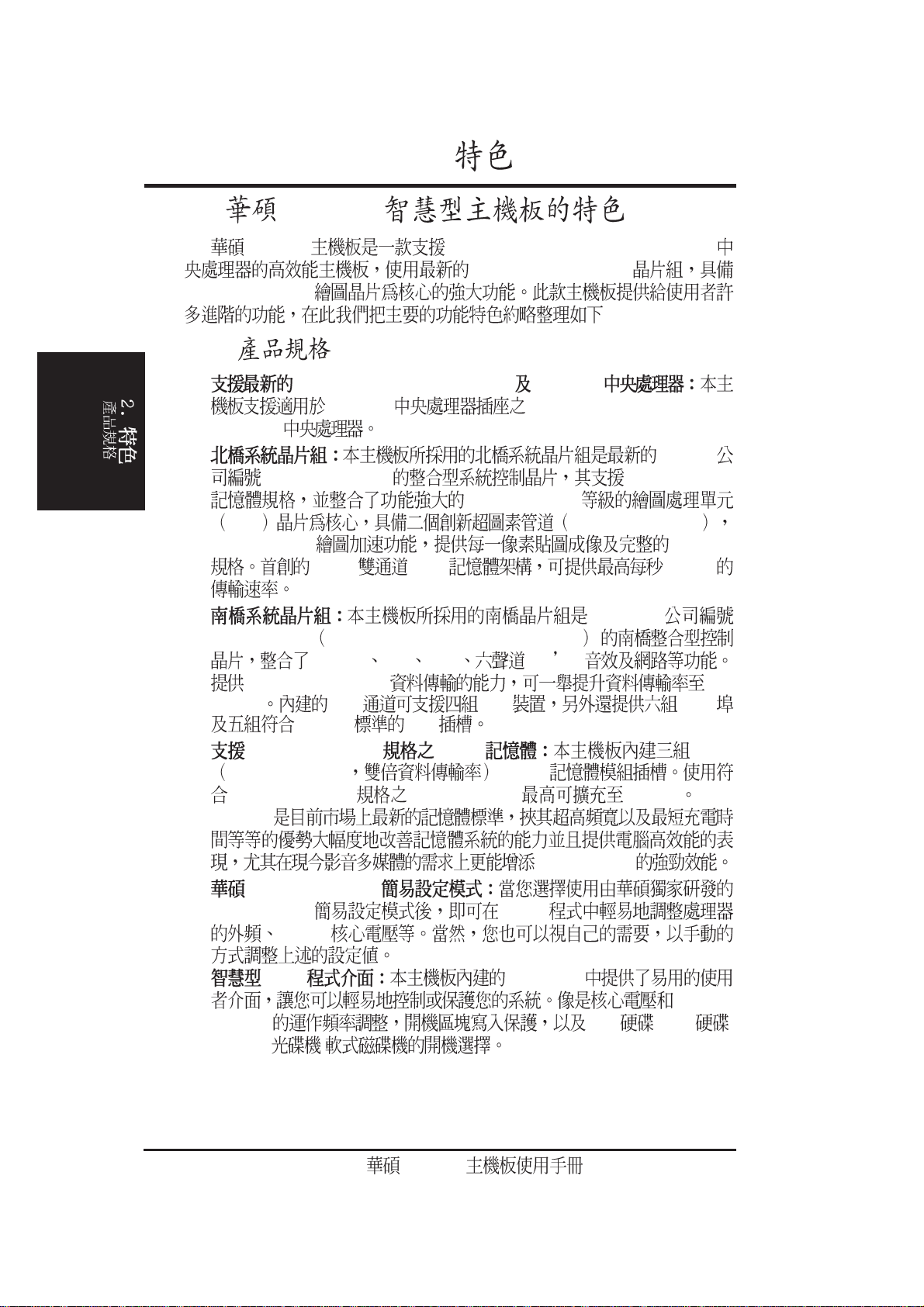
2.1 A7N266
2.
A7N266 AMD
GeForce2
TM
MX
®
Athlon™ XP /Athlon
nVidia
®
nForce 420
™
™
/Duron
:
2.1.1
•
AMD Athlon™ XP /Athlon
Socket A AMD Athlon XP™ / Athlon
/ Duron
™
•
nForceTM IGP-128 64/128 bit DDR
GeForce 2 MX
GPU hypertexel pipelines
256-bit 3D/2D AGP 4X
128bit DDR 4.2 GB
•
nForceTM MCP Media and Communications Processor
PCI Bus IDE USB AC 97
UltraDMA 100/66/33 100
MB/sec IDE IDE USB
PCI 2.2 PCI
•
PC2100/PC1600 DDR DDR
Double Date Rate DIMM
PC2100/PC1600 DDR SDRAM 1.5 GB DDR
SDRAM
™
Duron
™
nVidia®
nVidia®
™
™
DDR SDRAM
•
JumperFreeTM
JumperFreeTM BIOS
Vcore
•
BIOS 2Mb FWH
CPU/
SDRAM IDE /SCSI /
MO/ZIP/ /
8
A7N266
Page 9
2.1.2
2.
CPU AMD Athlon™ XP / Athlon™ / Duron
•
A(462)
PCI 32 PCI 2.2
•
SCSI PCI
IDE IDE Ultra DMA 100/66
•
PIO 3 &4 IDE DVD
CD-RW
AGP Pro AGP Pro
•
AGP 4X 1.5 AGP AGP Pro
•
USB USB USB
•
PDA
•
•
•
•
( )
™
133MB
( )
Socket
2.
•
•
•
PS/2 PS/2 ( )
•
PS/2 PS/2 ( )
•
•
•
ATX
•
/
MIDI
LED
AGP 3.3V AGP
ATX
( )
A7N266
9
Page 10
2.1.3
2.
•
•
•
•
UltraDMA/100 IDE IDE
( ) IDE
IDE PIO Mode 3 4
UltraDMA/100/66/33
100MB IDE
MO LS-120
Multi-I/O UART
EPP ECP
DDR SDRAM DDR
SDRAM Double Data Rate SDRAM
SDRAM DDR 100MHz
133MHz
200MHz 266MHz 100MHz DDR SDRAM
1.6 GB/ 133MHz DDR SDRAM 2.1 GB/
HRTF 3D C-Media CMI8738 PCI
S/PDIF /
PC DVD 5.1/6.1 AC-3/DTS
DVD PCtel 56K
OK CMI8738 24 S/PDIF
SBPROTM FM /DLS
10
C.O.P. AMD
•
CPU CPU
CPU
•
•
ACPI
ACPI Advanced Configuration and Power Interface
2000 OSPM OS Direct Power
Management 24
ACPI ACPI
Windows 98/ME/2000
BIOS
PC 99
Windows 95/98/ME/NT/2000 32
A7N266
®
Athlon™ XP
Windows 98/ME/
Page 11
2.
•
BIOS
•
CPU
•
•
•
2000 OS/2
•
•
•
ACPI LED
Windows 95/98/ME Windows NT/
CPU ASIC
ASIC
A7N266
11
Page 12
2.2
2.
Socket A AMD Athlon
..............................................................................
®
nVidia
®
nVidia
- /
2Mbit
3 DDR DIMM
PC1600 / PC2100 DDR DRAM 1.5 GB
5 PCI
AGP Pro
1
1
I/O 1
2 IDE UltraDMA/100
1
1
VGA
1
1
USB
USB
IrDA
1
PS/2
1
1
PS/2
.....................................................................
........................................................
.........................................................
COM1
COM2
Port 0 Port 1
Ports 2/3/4/5
™
nForce
nForce
................................................................
ACR
..................................................
..................................................
IGP-128
™
MCP
........................................................
EEPROM
............................................................
.......................................................
...........................................
......................................................
..............................................
...................................................
................................................
Athlon XP™/ Duron
™/
................
...........................
.............................
.........................................
.................
ASIC
.................
™
......
12
18
22
15
25
24
26
10
27
13
11
28
28
14
1
2
8
9
3
7
6
12
Realtek LAN
LAN(RJ-45)
CMI8738
Aux CD
1
1
1
1
ATX
/MIDI
AGP
ATX
A7N266
........................................................
...................................................
...........................................
................................................................
.....................................
.................................................
............................................
................................................
....................................................
.............................................................
...............................................
..............................
(
( ) 21
17
27
20
16
19
23
23
23
23
4
) 5
Page 13
235
28
1
6
0
4
27
26
25
24
23
2.
-
22
21
20
19
18
17
16
15
14
13
12
7
8
9
1
11
A7N266
13
Page 14
24.5cm (9.64in)
3.1
3.
PS/2
USB1
RJ-45
USB2
COM1
VGA
GAME_AUDIO
INT_LINEIN
INT_MIC
HEADPHONE
SPDIF
AUD_EN
AUX
CD
MODEM
LAN_EN
C-Media
CMI8738
Realtek
RTL8100
BCS1
BCS2
USBPWR01
Socket 462
JEN
BSEL0
BSEL1
ACR
CPU
AGP PRO
PCI
PCI
PCI
PCI
PCI
nVidia
nForce
IGP-128
WARNING
CPU_FAN
NB_FAN
USB45 USB23
01
DDR DIMM1
0 1012 3
nVidia
MCP
USBPWR45
USBPWR23
A7N266
01
VDDR
DDR DIMM2
DDR DIMM3
4 5
VID1
VID2
JTPWR
VID3
VID4
BUZZER
IDELED
PANEL
CHA_FAN
PLED
ATX
CR2032 3V
CMOS
2Mb
BIOS
Super
CLRTC
SMB
CHASSIS
IDE
I/O
IDE
FLOPPY
30.5cm (12.0in)
COM2
IR
14
A7N266
Page 15
3.
3.2
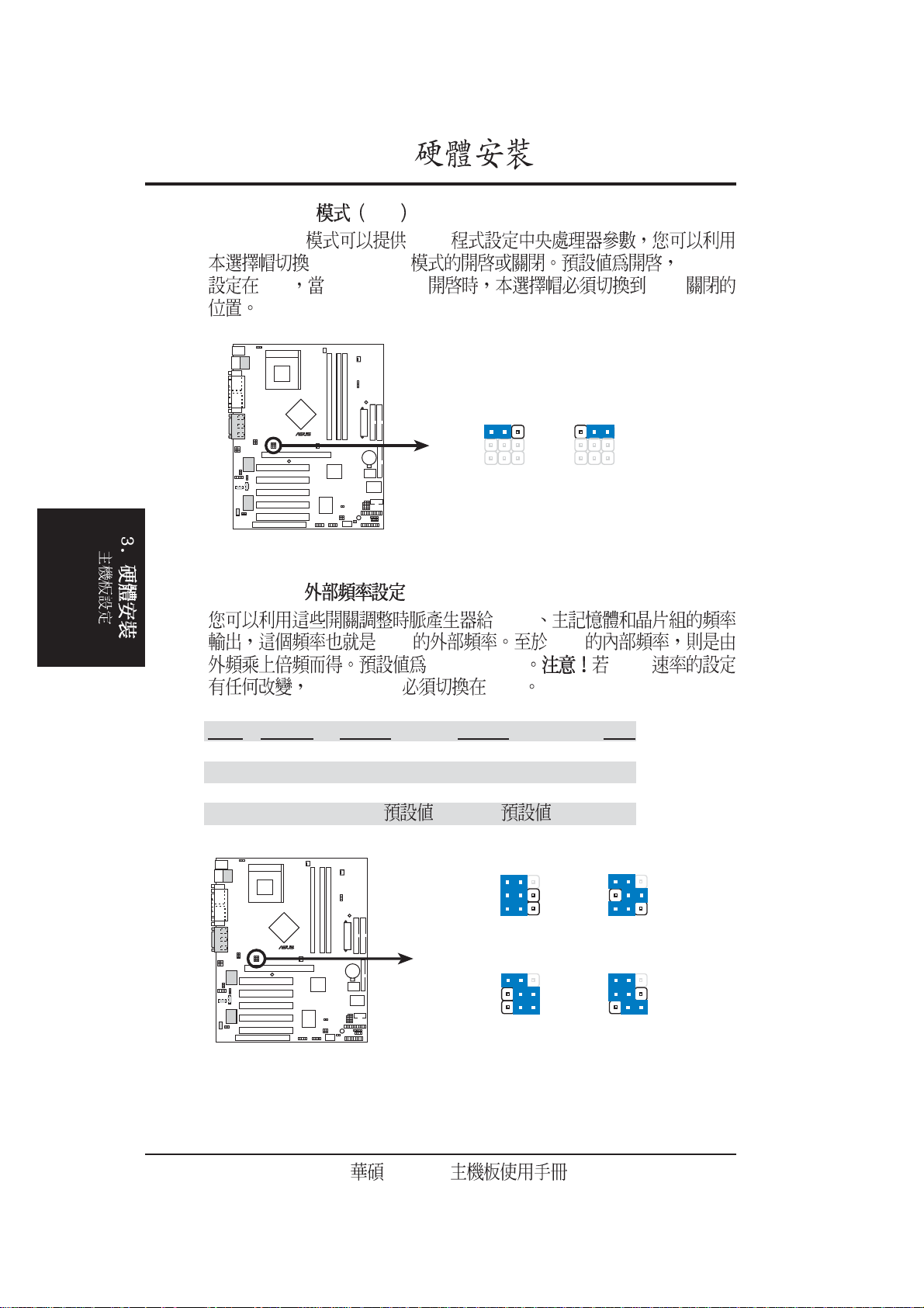
1) PLED, WARNING p.17 AGP
2) JEN p.18 JumperFree /
3) BSEL0, BSEL1 p.18
4) VID 1,2,3,4 p.19 1.675V
5) VDDR p.19 DDR (2.7V, 2.6V, 2.5V)
6) BCS1, BCS2 p.20 Bass / Center Setting (Center/Bass, Bass/Center)
7) LAN_EN p.20 ( / ) ( )
8) AUD_EN p.21 ( / ) ( )
9)
USB01 / USB23 / USB45PWR
10) CLR_RTC p.22 CMOS 2 pin
1) DIMM 1/2/3 p. 23
2) Socket 462(Socket A) p. 26 AMD
3) PCI1/2/3/4/5 p. 27 32 PCI
4) AGP PRO p. 29 AGP Pro
5) ACR p. 30 ACR
p.21 USB
\ \
1) PS2KBMS p. 31 PS/2 6 pin
2) PS2KBMS p. 31 PS/2 6 pin
3) USB p. 32 0 & 1 4-pin
4) PRINTER p. 32 25-pin
5) RJ-45 p. 32
6) COM1/COM2 p. 33 9-pin
7) VGA p. 33 25-pin
8) GAME_AUDIO p. 34 /MIDI 15-pin
9) AUDIO p. 34 1/8
10) IDELED p. 35 IDE 2 pins
11) FLOPPY p. 35 34 pins
12) PRIMARY/SEC. IDE p. 36 IDE 40-1 pins
13) CPU/PWR/CHA_FANp. 37 CPU/ / 3 pins
14) USB2_3/USB4_5 p. 37 10-1 pins
15) IrDA p. 38 10-1 pins
16) ATXPWR p. 39 ATX 20 pins
CPU:DRAM (100:100, 100:133, 133:100, 133:133)
1.85V
~
(+5V / +5VSB)
A7N266
15
Page 16
3.
17) SMB p. 39 SMBus 5-1 pins
18) CD/AUX/MODEM p. 40 12-1 pins
19) INT_MIC p. 40 3 pins
20) HPHONE p. 41 3 pins
21) INT_LINEIN p. 41 3 pins
22) S/PDIF p. 42 2 pins
23) CHASSIS p. 42 4-1 pins
24) JTPWR p. 43 2 pins
25) PWR.LED p. 44 3 pins
26) KEYLOCK p. 44 2 pins
27) SPEAKER(PANEL) p. 44 4 pins
28) LED p. 44 2 pins
29) SMI p. 44 SMI 2 pins
30) PWR p. 44 ATX / 2 pins
31) RESET p. 44 2 pins
3.3
1. Jumper
2.
3. CPU
4.
5.
6. BIOS
16
A7N266
Page 17

3.
®
PLED
d
d
3.4
Switch Jumper
1.
2. CPU, RAM
3.
4.
5. ATX ATX
LED
LED
1) (LED - Light Emitting Diodes)
(LED1) (1)
(2) (3) AGP
3.3 AGP
AGP (+3.3V)
AGP
A7N266
010101
A7N266 Onboard LED
ON
Standby
Power
WARNING
ON
Incorrect
AGP Card
OFF
Powere
Off
OFF
Correct
AGP Car
1.5
A7N266
17
Page 18
3.
®
)
®
t)
z
z
z
z
2) JumperFreeTM JEN
JumperFree
™
JumperFree
BIOS
™
[2-3] BSEL jumpers [1-2]
A7N266
010101
12
Disable
A7N266 Jumper Mode Setting
3) CPU:DRAM (BSEL0, BSEL1)
CPU
CPU CPU
100:100 Mhz CPU
JEN jumper [1-2]
JEN
23
Enable
(Default
jumpers
18
CPU DRAM BSEL0 BSEL1 JEN
133 133 [1-2] [1-2] [1-2]
133 100 [2-3] [1-2] [1-2]
100 133 [2-3] [2-3] [1-2]
100 100 [1-2] ( ) [2-3] ( ) [1-2]
A7N266
010101
A7N266 CPU
External Frequency Selection
12
JEN
BSEL0
BSEL1
CPU 133MHz
DRAM 133MHz
JEN JEN
BSEL0
BSEL1
CPU 100MHz
DRAM 133MHz
3
312
12
12
JEN
BSEL0
BSEL1
CPU 133MH
DRAM 100MH
BSEL0
BSEL1
CPU 100MH
DRAM 100MH
(Defaul
A7N266
3
3
Page 19
3.
®
s
®
4) (VID1, VID2, VID3, VID4)
CPU Default
jumper
A7N266
010101
VID1
VID2
VID3
VID4
(CPU Default)
12
34
VID1
VID2
VID3
VID4
1.85/1.825Volts
12
34
12
VID1
VID2
VID3
VID4
1.80/1.775Volt
34
A7N266 CPU Core Voltage
Selection
5) DDR (VDDR)
DDR
Setting VDDR
2.7V [1-2]
2.6V [2-3] ( )
2.5V [3-4]
A7N266
010101
34
12
VID1
VID2
VID3
VID4
1.75/1.725Volts
VDDR
1
22
2.7V
33
2.6V
(Default)
VID1
VID2
VID3
VID4
1.70/1.675Volts
4
2.5V
12
34
A7N266 VDDR Setting
A7N266
19
Page 20
3.
®
®
e
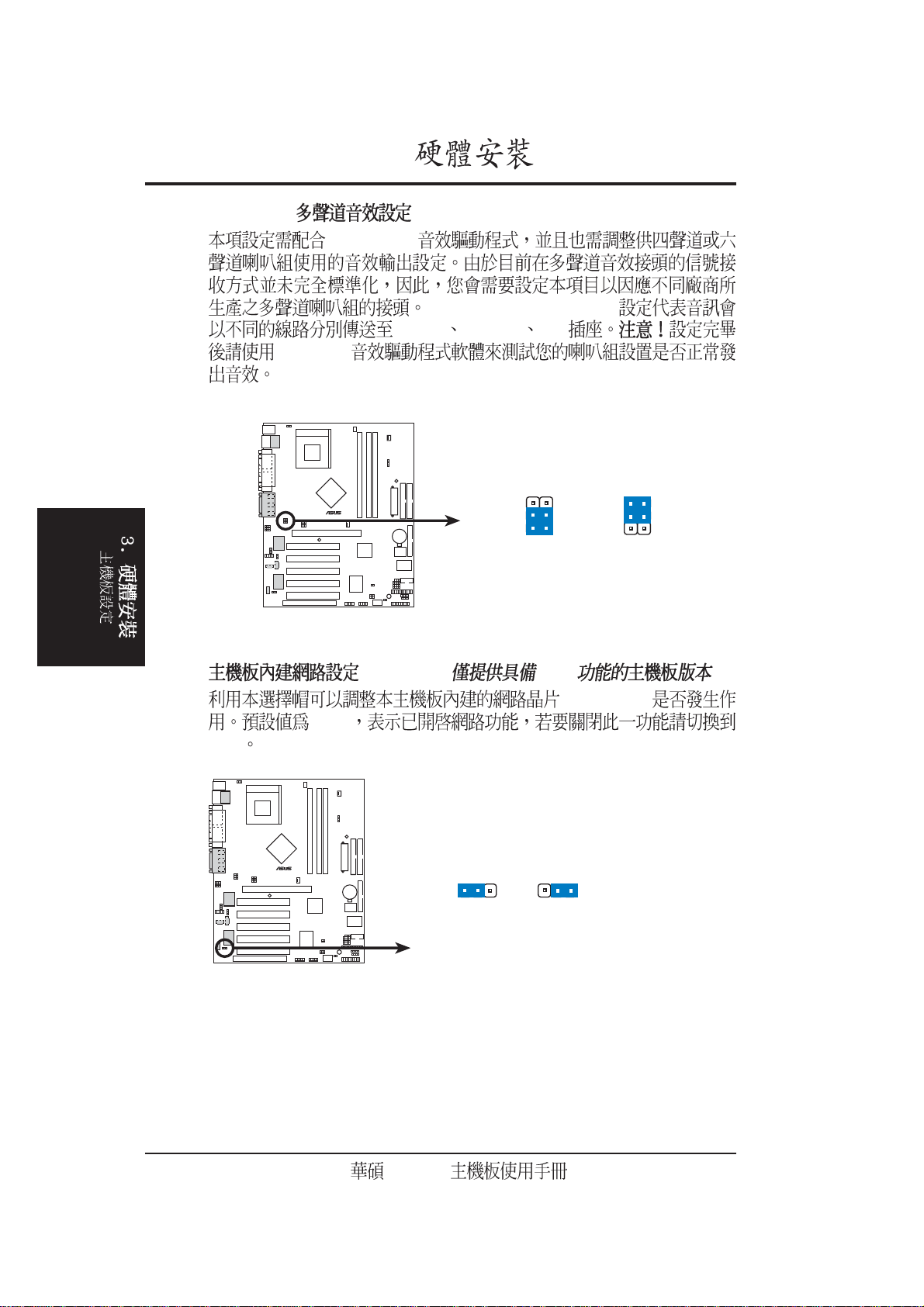
6) Bass Center (BCS1, BCS2)
C-Media PCI
Center/Bass, to Bass /Center
Line-In Line-Out Mic
C-Media
A7N266
010101
2
1
BCS1
BCS2
CENTER / BASS
(Default)
3
2
BCS1
BCS2
BASS / CENTER
A7N266 Bass Center Setting
7) (LAN_EN) ( LAN )
(RTL8100)
[1-2]
[2-3]
A7N266
010101
LAN_EN
12
Enable
(Default)
23
Disabl
A7N266 On Board LAN Setting
20
A7N266
Page 21
3.
®
e
®
8) (AUD-EN) ( )
[1-2] PCI
ACR [2-3] (
3.7.3, ACR )
A7N266
010101
AUD_EN
2
1
Enable
(Default)
3
2
Disabl
A7N266 Audio Codec Setting
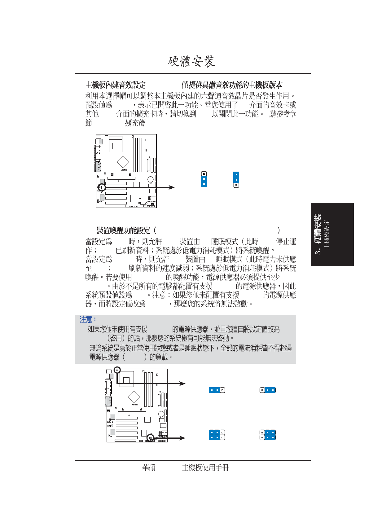
9) USB USB01_PWR/USB23_PWR/USB45_PWR
+5V USB S1 CPU
RAM
+5VSB USB S3
CPU RAM
+5VSB 2A/
+5VSB +5VSB
+5V +5VSB
+5VSB
1. +5VSB Enabled
2.
+5VSB
A7N266
010101
2
1
+5V
(Default)
USBPWR01
2
+5VSB
3
USBPWR45
USBPWR23
12
A7N266 USB Device Wake Up
+5V
(Default)
A7N266
23
+5VSB
21
Page 22
3.
®
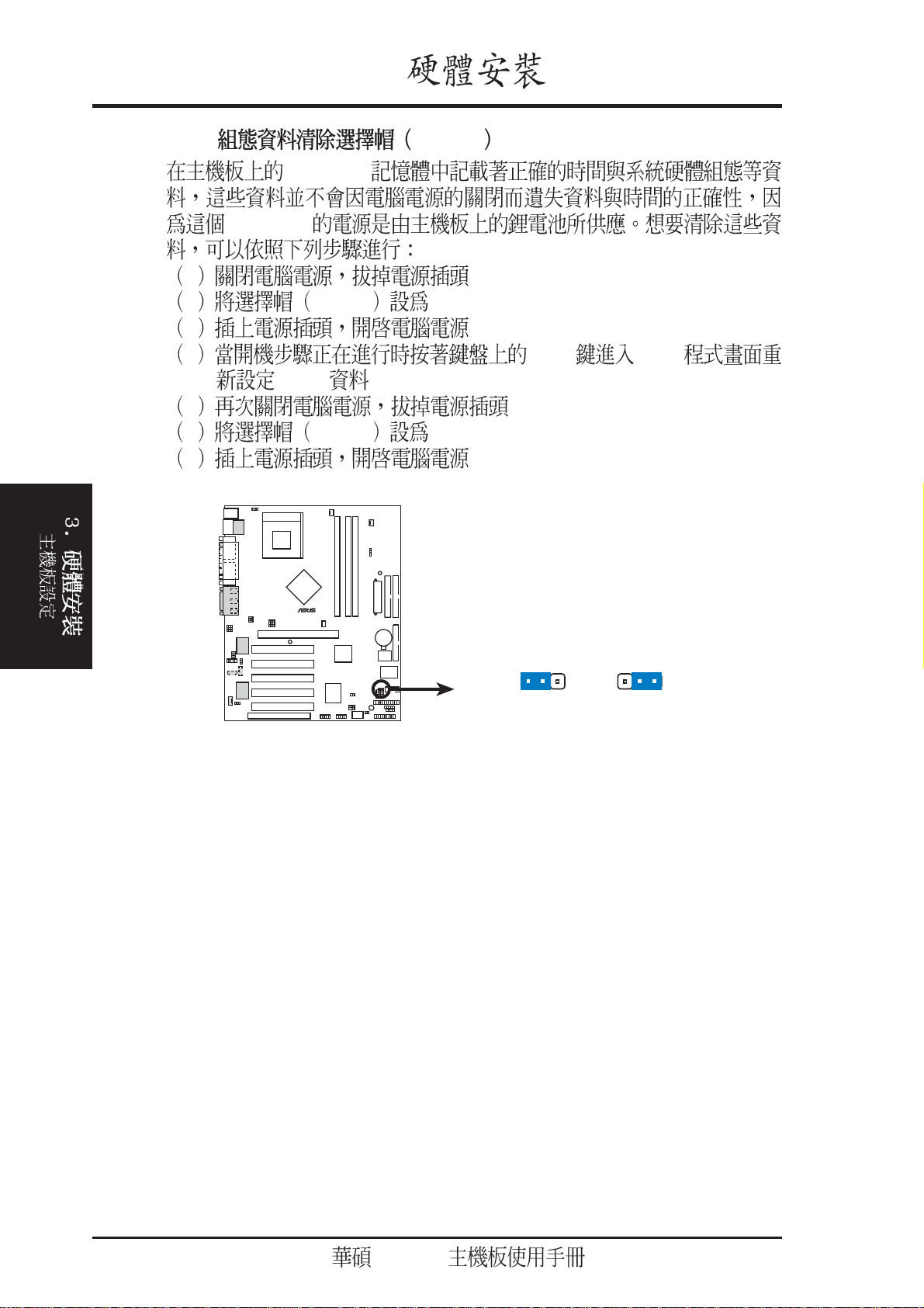
10) BIOS CLRTC
CMOS
CMOS
1
2 Jumper [2-3]
3
4 <Del> BIOS
BIOS
5
6 Jumper [1-2]
7
A7N266
010101
A7N266 Clear RTC RAM
CLRTC
12
Normal Clear CMOS
(Default)
23
22
A7N266
Page 23
3.
3.5 DDR SDRAM
3.5.1 DDR DIMM
DDR Double Data Rate DIMM
64, 128, 256, 512MB 2.5 DDR SDRAM
Double Data Rate Synchronous Dynamic Random Access Memory
64MB 1.5GB
DIMM
TwinBank
TM
128-bit DDR
4.2 GB/sec DIMM
DIMM 64-bit
DDR DIMM 184-pin non-ECC unbuf-
fered CAS Latency 2.0
(PC2100A) 2.5 (PC2100B) ( 25 DIMM )
1. DIMM
2. 5
DDR
DDR SDRAM
Capacity DIMM 1 (A0) DIMM2 (B0) DIMM3 (B1)
128 MB 64MB - 1B or 2B 64MB - 1B or 2B X
192 MB 128MB - 1B or 2B 64MB - 1B or 2B X
256 MB 128MB - 1B or 2B 128MB - 1B or 2B X
128MB - 1B or 2B 64MB - 1B or 2B 64MB - 1B
384 MB 256MB - 1B or 2B 128MB - 1B or 2B X
128MB - 1B or 2B 128MB - 1B or 2B 128MB - 1B
512 MB 256MB - 1B or 2B 256MB - 1B or 2B X
256MB - 1B or 2B 128MB - 1B or 2B 128MB - 1B
786 MB 512MB - 1B or 2B 256MB - 1B or 2B X
256MB - 1B or 2B 256MB - 1B or 2B 256MB - 1B
1 GB 512MB - 1B or 2B 512MB - 1B or 2B X
512MB - 1B or 2B 256MB - 1B or 2B 256MB - 1B
1.25 GB 512MB - 1B or 2B 512MB - 1B or 2B 256MB - 1B
1.5 GB 512MB - 1B or 2B 512MB - 1B or 2B 512MB - 1B
Table Legend:
1B = 1 bank: a single load module. 2B = 2 bank: a dual load module.
A7N266
23
Page 24
3.
®
s
3.5.2
184 DDR SDRAM
2.5V unbuffered DDR DIMM
A7N266
010101
104 Pin
A7N266 184-Pin DDR
DIMM Sockets
1.
2. SDR
3. SDR
80 Pins
24
A7N266
Page 25
1.
2.
3.5.3
3.
•
•
BIOS
•
•
•
128 256 512 MB
18 DIMM
SPD (Serial Presence Detect) DIMM
DIMM
64 128 256 MB
A7N266
25
Page 26
3.6 CPU
®
LOCK
AMD Athlon XP
3.
TM
Socket 462 Socket A
Athlon
TM
DuronTM
A7N266
010101
A7N266 Socket 462
1. Socket A
90
3. Socket A
Socket 462
4. Socket A
Socket A
CPU NOTCH
TO INNER
CORNER
CPU NOTCH
AMD™ Athlon
LEVER
26
5.
1 Socket A
2
3
Socket A
Socket A
A7N266
Page 27
3.
3.7
3.7.1
1.
2.
3.
4.
5.
6. BIOS
4.4.3 PCI IRQXX Used By ISA
7.
A7N266
27
Page 28
3.
3.7.2 IRQ
IRQ IRQ
AT 16
6 PCI
IRQ MIDI
IRQ IRQ 4
PCI PCI
IRQ IRQ
IRQ
IRQ
IRQ
01
12
2 N/A
3* 11 COM 2
4* 12 COM 1
5* 13 LPT 2
614
7* 15 LPT 1
83 CMOS/
9* 4 ACPI
10* 5 PCI
11* 6 PCI
12* 7 PS/2
13 8
14* 9 IDE
15* 10 IDE
28
*
A7N266
Page 29
3.
®
INT-A INT-B INT-C INT-D INT-E
PCI --- --- --- -- PCI --- --- --- -- PCI --- --- --- -- PCI --- --- --- ---
PCI --- --- --- --AGP Pro
ACR --- --- --- ---
USB --- --- --- ---
3.7.3 ACR
Phoneline Networking Alliance HomePNA
ACR AMR
--- --- --- ---
--- --- --- ---
Advanced Communication Riser
Home
ACR PCI
A7N266
010101
A7N266 Advanced
Communication Riser (ACR)
A7N266
29
Page 30

3.
An early 3.3V AGP card:
A new 1.5 / 3.3V AGP card:
®
3.7.4 AGP Pro
AGP Pro Accelerated Graphics Port
A7N266
010101
A7N266 Accelerated
Graphics Port (AGP PRO)
AGP Pro AGP
AGP Pro AGP Pro
AGP
AGP AGP Pro
AGP Pro
AGP Card without Retention Notch
20-pin bay
Rib (inside slot) Rib
AGP 6600
TOP VIEW
28-pin bay
AGP Pro
LED
Do not use.
3.3V AGP
1.5 / 3.3 V AGP
OKAY to use.
1.5V AGP AGP 4X
1.5 3.3 V AGP 3.3V
AGP 4X 3.3V AGP
SiS305 AGP 3.3V AGP
30
A7N266
Page 31

3.
3.8
15
1 PS/2 6-pin P2KBMS
PS/2 IRQ12 PS/2
PS/2
BIOS
PS/2 Mouse (6-pin female)
1
46
2 PS/2 6-pin P2KBMS
PS/2 mini DIN AT
large DIN PS/2
AT
PS/2 Keyboard (6-pin female)
A7N266
31
Page 32

3.
RJ-45
Parallel (Printer) Port (25-pin female)
3 USB0 / USB1 4-pin USB
USB
USB USB
Universal Serial Bus (USB)
4 25-pin PRINTER
BIOS 4.4.2
5) (RJ-45) ( )
RJ-45 USB
32
(LAN)
A7N266
Page 33

3.
®
6 9-pin COM1 / COM2
COM1 COM2
BIOS 4.4.2 /
010101
COM 1
A7N266
Serial Port (9-pin male)
A7N266 Serial COM2 Bracket
7) (Blue 15-pin VGA)
VGA
COM2
PIN 1
VGA Monitor (15-pin female)
A7N266
33
Page 34

3.
8) /MIDI 15-pin GAME_AUDIO
MIDI
Game/MIDI (15-pin female)
9) 1/8
Line Out
Line In
Line Out Mic
34
MicLine InLine Out
1/8" Stereo Audio Connectors
A7N266
Page 35

3.
®
t
®
n
10 IDE 2 pin IDELED
IDE IDE
IDE
A7N266
010101
TIP: If the case-mounted LED does no
light, try reversing the 2-pin plug.
A7N266 IDE Activity LED
IDE
IDE
IDELED
11 34-1 pin FLOPPY
A7N266
010101
A7N266 Floppy Disk Drive Connector
NOTE: Orient the red markings o
the floppy ribbon cable to PIN 1
PIN 1
A7N266
35
Page 36

3.
®
s
r
12 / IDE
(40-1 pin Primary IDE/Secondary IDE)(40-1 pin Promise IDE1 /Promise IDE2)
IDE IDE
IDE ( CD-ROM MO )
Primary
Secondary Master
UltraDMA/100/66 IDE
IDE
Slave UltraDMA/100/66 IDE
Secondary BIOS
4.6 UltraDMA100 /
UltraDMA66 UltraDMA100 / UltraDMA66
UltraDMA/100 UltraDMA/66 IDE 40- 80- IDE
100MB/s 66MB/s
A7N266
010101
NOTE: Orient the red marking
(usually zigzag) on the IDE
ribbon cable to PIN 1.
Secondary IDE Connecto
A7N266 IDE Connectors
Primary IDE Connector
PIN 1
36
A7N266
Page 37

3.
®
®
13 / /
CPU_FAN, PWR_FAN, CHA_FAN
Minute
CPU CPU
A7N266
010101
350mA 4.2 12
RPM Rotations Per
CHA_FAN
GND
+12V
Rotation
Rotation
CPU_FAN
NB_FAN
A7N266 12-Volt Cooling Fan Power
14 10-1 pin USB2_3, USB4_5
USB
USB USB USB
USB
A7N266
010 10 1
GND
USBP5+
USBP5–
USB Power
610
15
NC
GND
USBP4–
USBP4+
USB Power
A7N266 Front Panel USB Headers
GND
+12V
Rotation
GND
+12V
Rotation
USB
USB23USB45
NC
GND
USBP3+
GND
USBP2+
USBP3–
USB Power
610
15
USBP2–
USB Power
A7N266
37
Page 38

3.
®
)
15 IrDA 5 pin IR
IrDA
IrDA
COM2 IrDA
A7N266
010101
SIR
CIR
4.4.2 UART2
GND
IRRX
IRTX
+5 V
Standard Infrared (SIR)
NC
NC
GND
IR_CON
CIRRX
+5VSB
Front View Back View
A7N266 Infrared Connector
SIR
CIR
IRTX
GND
IRRX
+5V
(NC
38
A7N266
Page 39

3.
®
®
16) ATX (20-pin block ATXPWR)
ATX
ATX +5VSB 10
+5VSB 720mA
A7N266
010101
ATXPWR
A7N266 ATX Power Connector
17 SMBus 5-1 pin SMB
SMBus System Management Bus
A7N266
010101
+3.3VDC
-12.0VDC
COM
PS_ON#
COM
COM
COM
-5.0VDC
+5.0VDC
+5.0VDC
+3.3VDC
+3.3VDC
COM
+5.0VDC
COM
+5.0VDC
COM
PWR_OK
+5VSB
+12.0VDC
SMBus
SMB
1
+5V
Ground
A7N266 SMBus Connector
A7N266
SMBCLK
SMBDATA
39
Page 40

3.
®
)
®
INT_MIC
18) (4-pin CD/AUX/MODEM )
A7N266
010101
AUX (White)
MPEG
Modem-In
Ground
Ground
Modem-Out
A7N266 Internal Audio Connectors
19) (3-p i n MIC2 )
A7N266
010101
MODEM
MIC Power
1
Left Audio Channel
MIC Input
Ground
Right Audio Channel
Ground
Right Audio Channel
Left Audio Channel
CD (Black
Ground
A7N266 Internal Microphone Connector
MIC2
40
A7N266
Page 41

3.
®
®
20) (3-pin HPHONE )
A7N266
010101
A7N266 True-Level
Line Out Header
MIC2
HEADPHONE
1
GND
HP OUT LT
HP OUT RT
21) (3-pin INT_LINEIN) ( )
A7N266
010101
INT_LINEIN
Left Channel
1
A7N266 Line In Connector
GND
Right Channel
A7N266
41
Page 42

3.
®
®
S
22) (2-p i n SPDIFOUT/CDSPDIFIN)
CD-ROM DVD-ROM CD-RW
CDSPDIFIN
SPDIFOUT
A7N266
010101
SPDIF
SPDIF_IN
+5V
SPDIF_OUT
A7N266 Digital Audio Connector
23 4-1 pin CHASSIS
7. CIDB
A7N266
010101
CHASSI
GND
GND
1
CIDB
Ground
Chassis Signal
+5Volt
(Power Supply Stand By)
1
A7N266 Chassis Open Alarm Lead
42
A7N266
Page 43

3.
®
d
®
24) (2-pin JTPWR)
A7N266
01010 1
JTPWR
JTPWR
A7N266 Power Supply Thermal Connector
A7N266
010101
A7N266 System Panel Connectors
Groun
Keyboard Lock
Power LED
PLED+
Message LED
SMI Lead
* Requires an ATX power supply.
PLED-
MLED-
MLED+
Speaker
Connector
Ground
Keylock
+5V
GND
PWR
Ground
ExtSMI#
ATX Power
Switch*
Ground
Speaker
Ground
Reset
Ground
Reset SW
A7N266
43
Page 44

3.
25) (3-1 pin PWRLED)
26) (2-pin KEYLOCK)
27) (4-pin SPEAKER)
28) (2-pin MSG.LED)
29) SMI (2-pin SMI)
Turbo BIOS 4.5 Power
Menu Suspend Mode ACPI
30) ATX / (2-pin PWRSW)
Windows 98
CPU clock
31) (2-pin RESET)
Reset
44
A7N266
Page 45

3.
3.9
1.
2.
3.
4. /
5.
a.
b. SCSI ( )
c.
ATX
6. ATX
Award BIOS
Award POST
30
3.
CPU
A7N266
45
Page 46

3.
3.
7. Del BIOS
*
Windows95/98
ATX
ATX
46
A7N266
Page 47

4. BIOS
4.1 BIOS
4.1.1
AFLASH.EXE BIOS BIOS
BIOS BIOS
AFLASH.EXE
BIOS
BIOS DOS
AFLASH DOS Winodws MS-
DOS BIOS
AFLASH
1. DOS FORMAT A:/S
AUTOEXEC.BAT
CONFIG.SYS
2. DOS COPY D:\AFLASH\AFLASH.EXE A:\
D AFLASH.EXE
3. BIOS
4. DOS A:\AFLASH Enter AFLASH
BIOS
4. BIOS
Flash Memory unknown
ACPI BIOS BIOS
A7N266
47
Page 48

4. BIOS
5. 1. Save Current BIOS to File Enter
Save Current BIOS To File
6. A:\XXX-XX.
XXX Enter
4. BIOS
BIOS
48
A7N266
Page 49

4. BIOS
4.1.2 BIOS
BIOS
BIOS BIOS
1. ( WWW FTP) BIOS
3
2.
3. A:\ AFLASH.EXE
4. MAIN MENU 2 Update BIOS Including Boot Block and
ESCD
5. Update BIOS Including Boot Block and ESCD
BIOS A:\XXX-XX.XXX Enter
6. Y
A7N266
BIOS
4. BIOS
49
Page 50

4. BIOS
7. AFLASH BIOS BIOS
Flashed Successfully
8. BIOS
4. BIOS
BIOS
BIOS
BIOS
50
A7N266
Page 51

4. BIOS
4.2 BIOS
BIOS Basic Input and Output System
BIOS
BIOS
BIOS
RUN SETUP BIOS
BIOS
EEPROM Electrical Erasable Programmable
Read-Only Memory BIOS EEPROM
BIOS BIOS
BIOS
CMOS RAM
BIOS
POST Power-On Self Test
DELETE DELETE
RESET ALT -
CTRL - DEL
BIOS
BIOS
4. BIOS
BIOS
BIOS
A7N266
51
Page 52

4. BIOS
4.2.1 BIOS
BIOS
MAIN
ADVANCED BIOS
POWER
BOOT
EXIT BIOS
4.2.2
4. BIOS
BIOS
<F1> or <Alt + H>
<Esc> or<Alt + X>
← or → (keypad arrow)
or ↓ (keypad arrows)
↑
- (minus key)
+ (plus key) or spacebar
<Enter>
<Home> or <PgUp>
Exit
<End> or <PgDn>
<F5>
<F10>
52
BIOS
A7N266
Page 53

4. BIOS
F1 Alt + H
PgUp PgDn
Home End
Enter Esc
Enter
ESC
BIOS F5
BIOS
4.7 BIOS
BIOS
BIOS
[ ] BIOS
BIOS
BIOS
BIOS
4. BIOS
A7N266
53
Page 54

4.3 Main Menu
BIOS
4. BIOS
4. BIOS
System Time [XX:XX:XX]
00 23 00 59 00 59 Tab Tab
+ Shift
System Date [XX/XX/XXXX]
1 12 1 31 00 99 Tab Tab +
Shift
Legacy Diskette A [1.44M, 3.5 in.]Legacy Diskette B [none.]
[360K 5.25 in.] [1.
2M 5.25 in.] [720K 3.5 in.] [1.44M 3.5 in,] [2.88M 3.5 in.][None]
Floppy 3 Mode Support [Disabled]
1.2MB 3.5
[Disable] [Drive A] [Drive B] [Both]
54
A7N266
Page 55

4. BIOS
4.3.1 Primary & Secondary Master/Slave
IDE
Auto
Type [Auto]
[Auto] IDE
BIOS IDE
:
......................................................................................................................................
[None] -
IDE BIOS IDE
FDISK
IDE
active
[Auto]
4. BIOS
A7N266
55
Page 56

[User Type HDD]
4. BIOS
4. BIOS
cylinders heads sectors
[None]
Translation Method [LBA]
LBA Logical Block Access
28 cylinders heads sectors
LBA
504MB LBA [LBA] [LARGE]
[Normal] [Match Partition Table] [Manual]
Cylinders
Cylinder
[User Type HDD] Trans-
lation Method [Manual]
Head
Head
[User Type HDD] Trans-
lation Method [Manual]
56
Sector
Sector
[User Type HDD]
Translation Method [Manual]
A7N266
Page 57

4. BIOS
CHS Capacity
BIOS CHS
Maximum LBA Capacity
BIOS LBA
Multi-Sector Transfers [Maximum]
[User Type HDD] : [Dis-
abled] [2 Sectors] [4 Sectors] [8 Sectors] [16 Sectors] [32 Sectors] [Maximum]
SMART Monitoring [Disabled]
S.M.A.R.T. (Self-Monitoring, Analysis and Reporting
Technology)
[Disabled] [Enabled]
PIO Mode [4]
PIO Programmed Input/Output
IDE Mode 0 Mode 4 [0] [1]
[2] [3] [4]
Ultra DMA Mode [Disabled]
Ultra DMA
[Disabled] Ultra DMA [Type]
[User] UltraDMA Mode [0] [1] [2] [3] [4] [Disabled]
[CD-ROM] - IDE
[LS-120] - LS-120
[ZIP-100] - ZIP-100
[MO] - IDE
[Other ATAPI Device] - IDE
IDE
4. BIOS
Esc
Main Main
A7N266
57
Page 58

4.3.2
4. BIOS
Boot Up NumLock Status [On]
[Off] [On]
Keyboard Auto-Repeat Rate [12/Sec]
4. BIOS
Sec] [12/Sec] [15/Sec] [20/Sec] [24/Sec] [30/Sec]
Keyboard Auto-Repeat Delay [1/4 Sec]
[1/2 Sec] [3/4 Sec] [1 Sec]
Language [English]
Number Lock
[6/Sec] [8/Sec] [10/
[1/4 Sec]
BIOS
58
A7N266
Page 59

4. BIOS
Supervisor Password [Disabled] / User Password [Disabled]
Enter
Enter 8
Enter
Enter
BIOS
Enter
Enter
BIOS Main BIOS
BIOS
Supervisor password User password
BIOS
Supervisor
BIOS
CMOS
RTC
RTC
1
2 Jumper [2-3]
3
4 <Del> BIOS
BIOS
5
6 Jumper [1-2]
7
Halt On [All Errors]
[All Errors] [No Errors]
[All,But Keyboard] [All,But Diskette] [All,But Disk/Key]
Installed Memory [XXX MB]
4. BIOS
A7N266
59
Page 60

4. BIOS
4.4 Advanced Menu
4. BIOS
Current CPU Speed
CPU JumperFree
CPU/PCI multiple CPU
CPU Speed [Manual]
[Manual]
System Frequency Multiple (9.5x )
AMD
BIOS
CPU Speed
System/PCI Frequency
(MHz)
[5x][5.5x][6.0x]...[12.0x][12.5x]
CPU/PCI Frequency(MHz) (100/33)
PCI
CPU CPU
[103/33] ... [158/33]
CPU/Memory Frequency Ratio [Auto]
CPU/PCI Frequency(MHz)
[1:1] [3:4]
60
A7N266
Page 61

4. BIOS
CPU Level 1 Cache, CPU Level 2 Cache [Enabled]
[Disabled] [Enabled]
CPU Level 2 Cache ECC Check [Disabled]
ECC [Disabled] [Enabled]
BIOS Update [Enabled]
BIOS CPU
BIOS CPU
[Disabled] [Enabled]
PS/2 Mouse Function Control [Auto]
Auto PS/2 MOUSE
IRQ 12 PS/2 MOUSE IRQ 12
[Enabled] PS/2 MOUSE IRQ
12 PS/2 MOUSE [Enabled] [Auto]
USB Legacy Keyboard Support [Disabled]
USB [Disabled]
USB [Primary]
[Secondary] USB012 USB345 USB
[Disabled] [Primary] USB [Disabled]
[Primary] [Secondary]
OS/2 Onboard Memory > 64M [Disabled]
OS/2 64MB
[Enabled] [Disabled] [Disabled]
[Enabled]
4. BIOS
A7N266
61
Page 62

1.
2.
4. BIOS
CPU
CPU CPU
100MHz
BIOS BIOS
BIOS
CMOS CMOS
CMOS RTC ( 22 59
)
CPU
4. BIOS
3. CPU 1
4. CPU 2
CPU Upgrade/Reinstallation
BIOS
100MHz
CPU
CPU
CPU
CPU
CPU
CPU
62
A7N266
Page 63

4. BIOS
4.4.1 Chip Configuration
SDRAM Configuration [By SPD]
2 5
[By SPD] SPD (Serial Presence Detect)
2 5 EEPROM
memory type size speed voltage
module banks [User Define][7ns(143MHz)][8ns(125MHz)]
[By SPD] SDRAM Configuration [User Define]
SDRAM CAS Delay [Auto (Normal)]
SDRAM /
[Auto (Normal)] [2.0T (Normal)] [2.5T (Normal)] [Auto (TURBO)]
[2.0T (TURBO)] [2.5T (TURBO)]
Clock Spread Spectrum Mode [Center Spread]
[Center Spread] [Spread Down] [Disabled]
VGA Shared Memory Size [32MB]
VGA [8MB]
[16MB] [32MB]
4. BIOS
Graphics Aperture Size [64MB]
AGP
[32MB] [64MB] [128MB] [256MB] [512MB]
A7N266
63
Page 64

4. BIOS
Internal Graphic Over-clocking [Disable]
VGA LCD TV Display Type [Auto]
Video Memory Cache Mode [UC]
[Disable] [Enable]
[Auto]
[UC] [USWC]
Onboard VGA BIOS Update [Enabled]
MCP IDE Controller [Both]
MCP USB Controller [Enabled]
Keyboard support USB
MCP Audio Controller [Auto]
4. BIOS
MCP DOLBY DIGITAL Controller [Auto]
USWC
uncacheable, speculative write combining
UC uncacheable
[Enabled] [Disabled]
[Both] [Primary] [Secondary] [Disabled]
USB USB Legacy
[Enabled] [Disabled]
A7N266-E [Disabled] [Auto]
A7N266-E [Disabled] [Auto]
PCI 2.1 Support [Enabled]
[Disabled] [Enabled]
64
A7N266
Page 65

4. BIOS
4.4.2 I/O Device Configuration I/O
Onboard FDC Swap A & B [No Swap]
[No Swap] [Swap AB]
Floppy Disk Access Control [R/W]
(R/W)
[Read Only]
Onboard Serial Port 1 [3F8H/IRQ4];
Onboard Serial Port 2 [2F8H/IRQ3]
COM 1 COM 2 COM 1 COM 2
[3F8H/IRQ4] [2F8H/IRQ3] [3E8H/IRQ4]
[2E8H/IRQ10] [Disabled]Onboard AC97 Modem Controller [Auto]
UART2 Use Standard Infrared [Disabled]
SIR
COM 2 COM 2
3.8
[Disabled] [Enabled]
Onboard Parallel Port [378H/IRQ7]
I/O
4. BIOS
Parallel Port Mode ECP DMA Select
[Disabled] [378H/IRQ7] [278H/IRQ5]
A7N266
65
Page 66

4. BIOS
Parallel Port Mode [ECP+EPP]
ECP
ECP ECP
DMA
Normal
EPP ECP
ECP+EPP Two-way
[Normal] [EPP] [ECP] [ECP+EPP]
ECP DMA Select [3]
ECP DMA Parallel Port Mode
ECP ECP DMA Select [1] [3]
[Disabled]
Onboard Game Port [200H-207H]
Game Port I/O [200H-207H] [208H-
20FH] [Disabled]
4. BIOS
I/O
Onboard MIDI [Disabled]
MIDI I/O [330H-331H] [300H-301H]
[Disabled]
66
A7N266
Page 67

4. BIOS
4.4.3 PCI Configuration PCI
Slot 1/5, Slot 2, Slot 3, Slot 4 IRQ [Auto]
PCI IRQ PCI
IRQ IRQ PCI
Auto [Auto] [NA]
[3] [4] [5] [7] [9] [10] [11] [12] [14] [15]
PCI/VGA Palette Snoop [Disabled]
MPEG
[Enabled]
[Disabled] [Disabled] [Enabled]
PCI Latency Timer [32]
[32]
Primary VGA BIOS [AGP VGA Card]
[Onboard VGA Card]
optimal [AGP VGA Card] [Onboard VGA]
PCI
4. BIOS
A7N266
67
Page 68

4. BIOS
PCI DMA
DMA x Reserved for Legacy Drive [No/ICU]
DMA PNP ISA
[No/ICU] DMA ICU ISA
DMA ICU DMA
[Yes] [No/ICU] [Yes]
4. BIOS
PCI
PCI UMB
TSM MEM Block BASE [No/ICU]
PnP ISA
C800 DFFF ISA ICU
MEM Block Size
ICU TSM MEM Block
BASE [No/ICU] [No/ICU] [C800] [CC00] [D000]
[D400] [D800] [DC00]
68
A7N266
Page 69

4. BIOS
4.4.4 Shadow Configuration
Video ROM BIOS Shadow [Enabled]
VIDEO BIOS ROM RAM
[Disabled] [Enabled]
C8000-DFFFF Shadow [Disabled]
ROM RAM
ROM
640K 1024K [Disabled] [Enabled]
4. BIOS
A7N266
69
Page 70

4.5 Power Menu
4. BIOS
Video Off Option [Suspend -> Off ]
Video Off Method [DPMS OFF]
4. BIOS
Reduce ON Blank Screen V/H SYNC + Blank DPMS Standby DPMS
Suspend DPMS (Display Power Management System) BIOS
GREEN Blank Screen
[DPMS Suspend] [DPMS OFF] [DPMS Reduce ON]
HDD Power Down [Disabled]
[Always On] [Suspend -> Off]
DPMS OFF DPMS
DPMS [Blank Screen]
[V/H SYNC+Blank]
DPMS BIOS
[Blank Screen] [V/H SYNC+Blank] [DPMS Standby]
[Disable] [1 Min] [2 Min] [3 Min]...[15 Min]
70
A7N266
Page 71

4. BIOS
PWR Button < 4 Secs [Soft off]
Soft Off ATX ATX
Suspend ATX
[Soft off] [Suspend]
4.5.1 Power Up Control
ATX
AC PWR Loss Restart [Disabled]
[Enabled]
[Disabled] [Enabled]
Power Up From P/S2 Keyboard [Space bar]
[Space bar] Space bar [Space
bar] [Disabled]
[Disabled]
4. BIOS
A7N266
71
Page 72

4. BIOS
4.5.2 Hardware Monitor
MB Temperature [xxxC/xxxF]
CPU Temperature [xxxC/xxxF]
POWER TemperatureN/A
4. BIOS
CPU Fan Speed [xxxxRPM]
CHIP Fan Speed [xxxxRPM]
PWR Fan Speed N/A
VCORE Voltage, +3.3V Voltage, +5V Voltage, +12V Voltage [xx.xxV]
CPU
CPU
[Ignore]
: Hardware Monitor found an
error. Enter Power setup menu for details : Press F1 to
continue, DEL to enter SETUP F1 DEL
72
A7N266
Page 73

4.6 Boot Menu
4. BIOS
Space
[Removable Devices] [IDE
Hard Drive] [ATAPI CD-ROM] [Other Boot Device]
Removable Device [Legacy Floppy]
[LS120] [ZIP-100] [ATAPI MO] [Disable]
IDE Hard Drive
IDE [Enter]
IDE
ATAPI CD-ROM
ATAPI IDE
[Enter] ATAPI
Other Boot Device Select [INT18 Device (Network)]
[Disabled] [SCSI Boot Device] [INT18 Device (Network)]
[Legacy Floppy]
4. BIOS
A7N266
73
Page 74

4. BIOS
Boot Virus Detection [Enabled]
BIOS
[Disabled] [Enabled]
Disabled
BIOS
Quick Power On Self Test [Enabled]
POST [Disabled] [Enabled]
Boot Up Floppy Seek [Enabled]
4. BIOS
[Enabled]
Interrupt Mode [APIC]
POST
BIOS A [Disabled]
[APIC] [PIC]
74
A7N266
Page 75

4.7 Exit Menu
4. BIOS
Exit BIOS
BIOS
: Esc
Exit Saving Change
BIOS CMOS
Enter
Yes CMOS BIOS No
BIOS
BIOS BIOS
Enter BIOS
Exit Discarding Change
BIOS
Enter
BIOS No BIOS
Yes CMOS
4. BIOS
A7N266
75
Page 76

Load Setup Default
F5 Enter
Yes BIOS
No BIOS
Discard Changes
Enter
Save Changes
BIOS
4. BIOS
BIOS
BIOS No BIOS
Enter Yes
BIOS No
Yes
BIOS
4. BIOS
76
A7N266
Page 77

5.1
Windows NT 4.0 Service Pack 3.0
5.2 Windows
5.
Windows 98/ME/2000
Windows 95 OSR 2.0
Windows Windows
Windows
Windows
Windows
Windows 98
5.
A7N266
77
Page 78

5.3 A7N266
E)
5.3.1
5.
E:\Setup.exe (
5.
Windows 98
NVIDIA nForce
•
( INF )
Win98 80
NVIDIA
•
Windows NT (
INF )
C-Media
•
Realtek RTL8139
•
RTL8139
•
•
Windows ME
NVIDIA VGA
& C-Media
V2.15.04
V3.28.07 ASUS Live Update
BIOS
Windows NT
Realtek
78
Microsoft DirectX 8.0a
•
PC-cillin 2000 V7.61
•
Microsoft DirectX 8.0a
PC-cillin
A7N266
Page 79

5.
•
•
•
•
•
•
•
•
Adobe Acrobat Reader V5.0: Adobe Acrobat Reader
PDF
Cyberlink & Cyberlink PowerPlayer SE
Cyberlink VideoLive Mail
E-Color 3Deep
LCD
BIOS CPU
CRT
5.3.2
Windows 98
5.
A7N266
79
Page 80

5.3.3 Windows 98
5.
nVidia
Win98 nVidia
1. PCI System Management Bus
2. PCI Standard Host CPU Bridge
3. PCI Standard RAM Controller
®
®
PCI System Management Bus
1.
2. PCI System Management Bus
3.
4.
5.
6.
7.
D D :\Drivers\Chipset\Nvidia\win9x\SMbus
5.
Windows 98
8.
9. PCI System Management
10.
11.
PCI Standard Host CPU Bridge (GART driver)
1.
2. PCI standard Host CPU Bridge
3.
4.
5.
6.
7.
D D :\Drivers\Chipset\Nvidia\win9x\Gart
8.
9. AGP Host to the PCI Bridge
10.
11.
80
A7N266
Page 81

5.
PCI Standard Ram Controller
1.
2. PCI standard RAM Controller
3.
4.
5.
6.
7.
D D :
\Drivers\Chipset\Nvidia\win9x\MemoryController
8.
9. NVIDIA nForce 220/420 Memory Controller NVIDIA
nForce 420 Memory Controller DDR
10.
A7N266
81
Windows 98
5.
Page 82

6.
6.
6.1
BIOS
1. Windows
/ / AsusUpdate Vx.
xx.xx
ASUSUpdate Vx.xx.x
2.
Next
3. /
FTP
Auto Select
Next
4. BIOS
Next
5. BIOS
82
BIOS
BIOS
A7N266
Page 83

6.2 - PC Probe
CPU
6.2.1
Show up in next execution
A7N266
83
Page 84

6.2.2
CPU
CPU
CPU
84
A7N266
Page 85

FAT
CPU
A7N266
85
Page 86

CPU CPU
86
A7N266
Page 87

6.2.3
CPU !!!
A7N266
87
Page 88

6.3
6.3.1 C-Media
1. C-Media
/ /PCI Audio
Application/Auto Rack/
C-Media
C-Media PCI
/
Mixer
2. C-Media
Advanced
In Line-Out Mic-In /
6.3.2 C-Media
1. C-Media
Multi-Channel Audio Demo
/ /PCI Au-
dio Application/
Multi-Chan-
nel Audio Demo
Line-
88
A7N266
Page 89

2. C-Media
Multi-Channel Audio Demo
3.
6.3.3 /
/
/
MicLine InLine Out
A7N266
89
Page 90

3Deep color Tuner
6.4 3Deep Color Tuner
3Deep color tuner 3D
3Deep color tuner
6.4.1 3Deep
1.
3Deep color tuner
2.
3.
90
A7N266
Page 91

4.
5.
6.
True Internet Color
True Internet Color
Setup
3Deep Color Tuner
®
6.4.2 3Deep
3Deep - 3Deep Control Panel 3Deep
3Deep
gamma Set Game
Gamma
Run Color Wizard
?
3Deep
- -
3Deep
A7N266
91
Page 92

PowerPlayer SE
6.5 CyberLink PowerPlayer SE
6.5.1 CyberLink PowerPlayer SE
PowerPlayer SE PowerPlayer
6.5.2 CyberLink PowerPlayer
CyberLink PowerPlayer SE
CD MP3
CyberLink PowerPlayer / /CyberLink
i-Power!
92
OK
A7N266
Page 93

6.6 CyberLink VideoLive Mail
CyberLink VideoLive Mail Plus 3.0 ( VLM 3)
VLM3 VLM 3
VLM 3
AVI
Internet
VLM 3 1:900 30 VLM 3
CIF (352 x 288 pixel) QCIF
(176 x 144) 500KB
VLM 3 Video for Windows Video for
Windows
VideoLive Mail
A7N266
93
Page 94

VideoLive Mail
6.6.1 VideoLive Mail
VideoLive Mail
VideoLive Mail CyberLink
VideoLive Mail x.x VLM3
6.6.2 VideoLive Mail
94
A7N266
 Loading...