


A400CG
Trouble Shooting Guide
HX8528-D48
A400CG
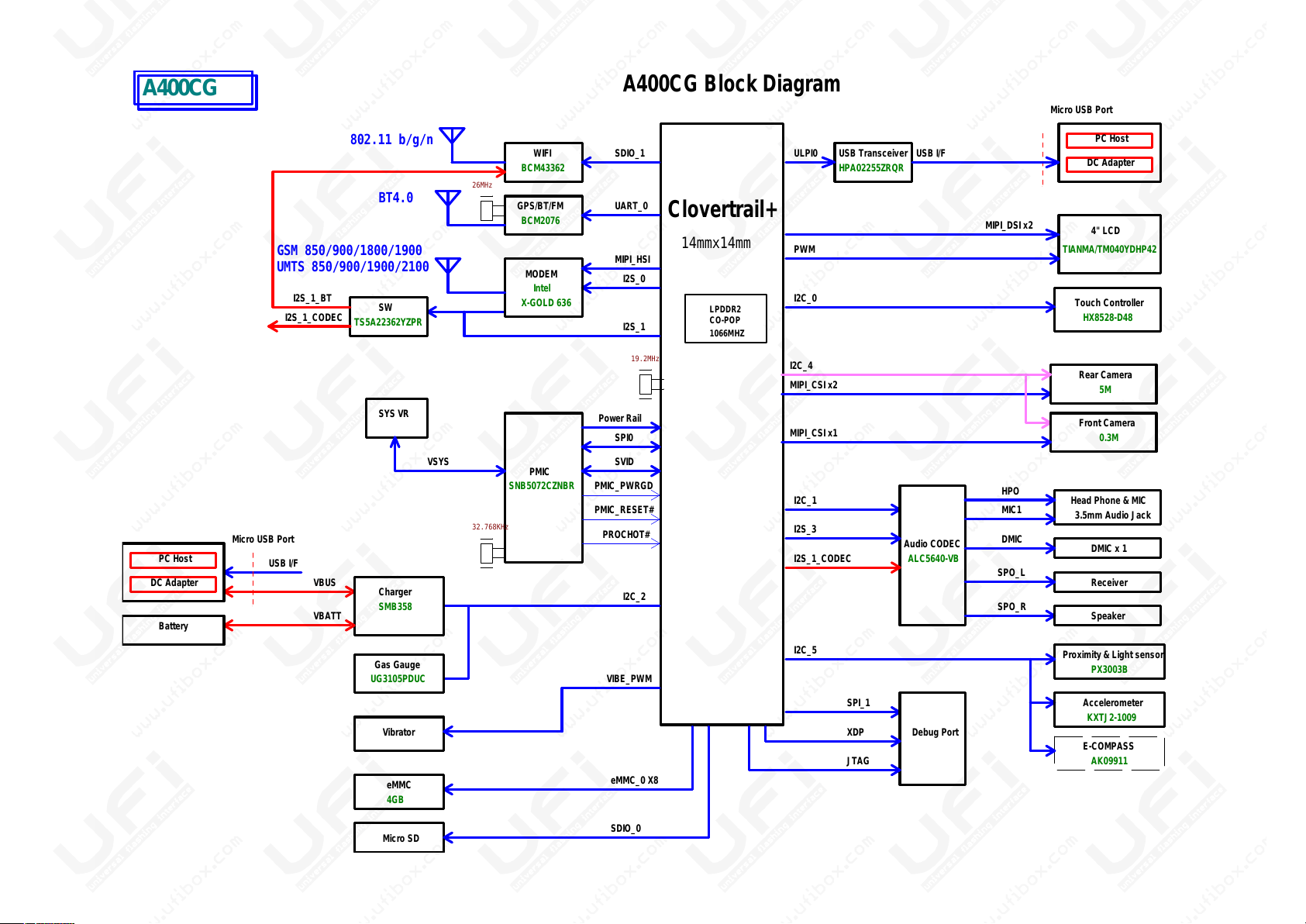
Clovertrail+
1066MHZ
LPDDR2
CO-POP
MIPI_CSI x2
14mmx14mm
Touch Controller
I2C_0
Micro USB Port
Front Camera
I2C_4
0.3M
Rear Camera
WIFI
GPS/BT/FM UART_0
SDIO_1
I2S_0
19.2MHz
26MHz
A400CG Block Diagram
5M
BCM43362
BCM2076
TIANMA/TM040YDHP42
4" LCD
X-GOLD 636
MODEM
MIPI_HSI
Intel
MIPI_DSI x2
GSM 850/900/1800/1900
UMTS 850/900/1900/2100
802.11 b/g/n
BT4.0
MIPI_CSI x1
HPA02255ZRQR
USB TransceiverULPI0
TS5A22362YZPR
SW
USB I/F
DC Adapter
PC Host
SYS VR
SPI0
I2S_1
I2S_1_BT
Power Rail
I2S_1_CODEC
PWM
HX8528-D48
A400CG
Clovertrail+
1066MHZ
LPDDR2
CO-POP
MIPI_CSI x2
14mmx14mm
Touch Controller
I2C_0
Micro USB Port
Front Camera
I2C_1 Head Phone & MIC
Audio CODEC
3.5mm Audio Jack
HPO
DMIC x 1
MIC1
DMIC
SPO_L
Receiver
I2S_3
I2C_4
0.3M
Rear Camera
WIFI
GPS/BT/FM UART_0
SDIO_1
eMMC_0 X8
eMMC
SDIO_0
Micro SD
I2S_0
19.2MHz
26MHz
A400CG Block Diagram
ALC5640-VB
5M
BCM43362
BCM2076
I2C_2
PX3003B
Proximity & Light sensor
I2C_5
TIANMA/TM040YDHP42
4" LCD
X-GOLD 636
MODEM
MIPI_HSI
Intel
MIPI_DSI x2
GSM 850/900/1800/1900
UMTS 850/900/1900/2100
802.11 b/g/n
BT4.0
MIPI_CSI x1
4GB
Speaker
SPO_R
Debug PortXDP
SPI_1
JTAG
HPA02255ZRQR
USB TransceiverULPI0
TS5A22362YZPR
SW
USB I/F
DC Adapter
PC Host
USB I/F
Micro USB Port
VBUS
SYS VR
Charger
SMB358
VSYS
PC Host
DC Adapter
Battery
Gas Gauge
VBATT
UG3105PDUC
PMIC
SVID
SPI0
I2S_1
PMIC_RESET#
PMIC_PWRGD
PROCHOT#
I2S_1_BT
Power Rail
I2S_1_CODEC
SNB5072CZNBR
32.768KHz
I2S_1_CODEC
AK09911
E-COMPASS
KXTJ2-1009
Accelerometer
PWM
Vibrator
VIBE_PWM
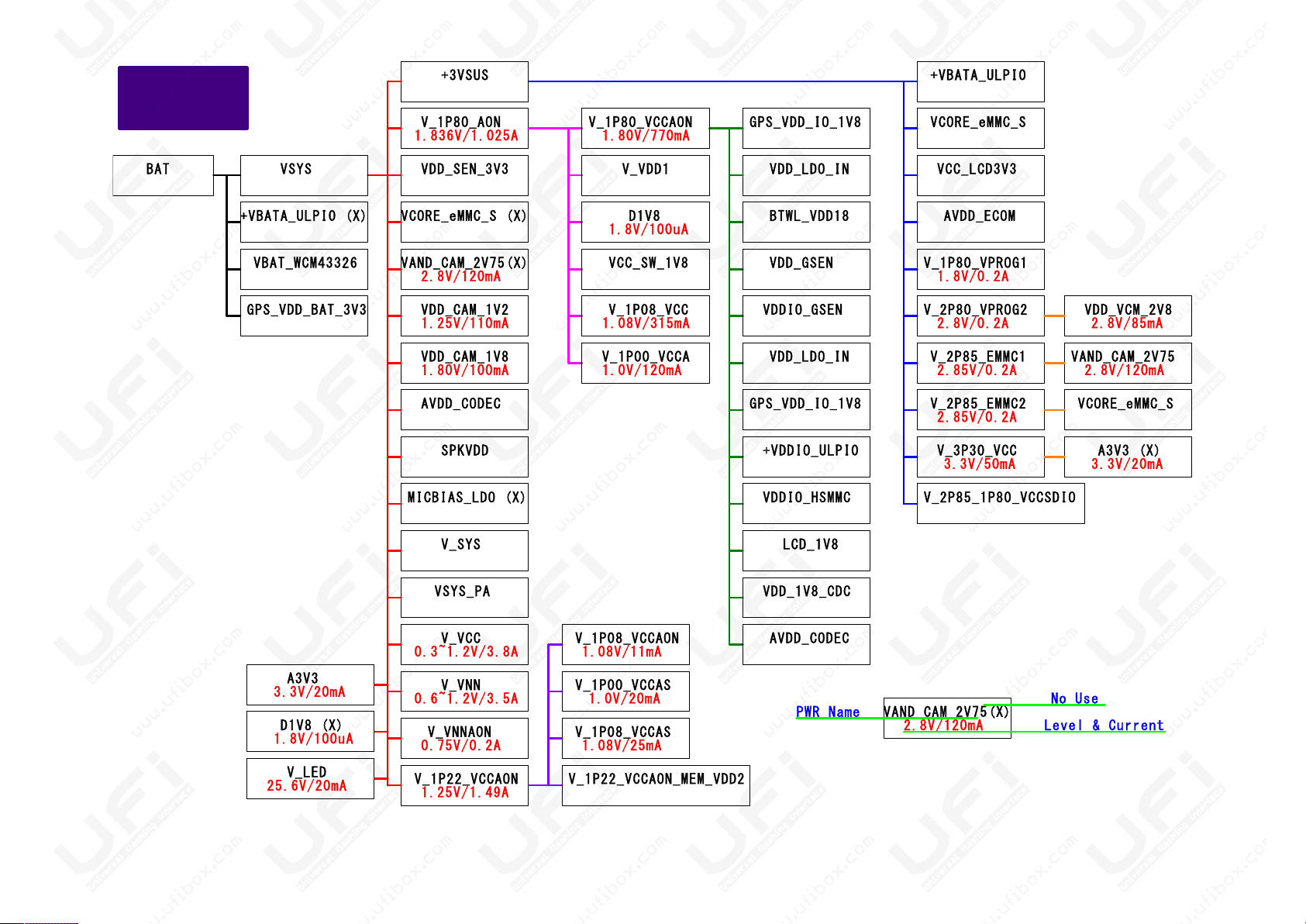
+3 VSUS
V_ 1P80 _AON
VD D_SE N_3V 3
VC ORE_ eMMC _S ( X)
VA ND_C AM_2 V75( X)
VD D_CA M_1V 2
VD D_CA M_1V 8
AV DD_C ODEC
SP KVDD
VD D_LD O_IN
GP S_VD D_IO _1V8
1. 8V/1 00uA
2. 8V/8 5mA
Power Tree
A400CG
2. 8V/1 20mA
1. 25V/ 110m A
2. 8V/1 20mA
1. 80V/ 100m A
AV DD_E COM
+V BATA _ULP I0
VC ORE_ eMMC _S
V_ 1P80 _VPR OG1
V_ 2P80 _VPR OG2
VC C_LC D3V3
V_ 2P85 _EMM C1
V_ 2P85 _EMM C2
V_ 3P30 _VCC
VD D_VC M_2V 8
VA ND_C AM_2 V75
VC ORE_ eMMC _S
A3 V3 ( X)
BT WL_V DD18
V_ VDD1
D1 V8
V_ 1P08 _VCC
V_ 1P00 _VCC A
VC C_SW _1V8
VD D_GS EN
VD DIO_ GSEN
VD D_LD O_IN
GP S_VD D_IO _1V8
V_ 1P80 _VCC AON
+V DDIO _ULP I0
VS YSBA T
+V BATA _ULP I0 ( X)
GP S_VD D_BA T_3V 3
VB AT_W CM43 326
1. 08V/ 315m A
2. 85V/ 0.2A
1. 80V/ 770m A1. 836V /1.0 25A
1. 0V/1 20mA
1. 8V/0 .2A
2. 8V/0 .2A
2. 85V/ 0.2A
LC D_1V 8
V_ 1P22 _VCC AON
+3 VSUS
V_ 1P80 _AON
VD D_SE N_3V 3
VC ORE_ eMMC _S ( X)
VA ND_C AM_2 V75( X)
VD D_CA M_1V 2
VD D_CA M_1V 8
AV DD_C ODEC
SP KVDD
MI CBIA S_LD O (X )
V_ SYS
VS YS_P A
V_ VCC
V_ VNN
V_ VNNA ON
D1 V8 ( X)
V_ LED
A3 V3
VD D_LD O_IN
GP S_VD D_IO _1V8
1. 8V/1 00uA
1. 8V/1 00uA
3. 3V/2 0mA
3. 3V/2 0mA
2. 8V/8 5mA
Power Tree
A400CG
2. 8V/1 20mA
1. 25V/ 110m A
2. 8V/1 20mA
25 .6V/ 20mA
1. 80V/ 100m A
AV DD_E COM
+V BATA _ULP I0
VC ORE_ eMMC _S
V_ 1P80 _VPR OG1
V_ 2P80 _VPR OG2
VC C_LC D3V3
V_ 2P85 _1P8 0_VC CSD IO
V_ 2P85 _EMM C1
V_ 2P85 _EMM C2
V_ 3P30 _VCC
VD D_VC M_2V 8
VA ND_C AM_2 V75
AV DD_C ODEC
VD D_1V 8_CD C
V_ 1P08 _VCC AON
V_ 1P22 _VCC AON_ MEM _VDD 2
V_ 1P00 _VCC AS
V_ 1P08 _VCC AS
VC ORE_ eMMC _S
A3 V3 ( X)
BT WL_V DD18
V_ VDD1
D1 V8
V_ 1P08 _VCC
V_ 1P00 _VCC A
VC C_SW _1V8
2. 8V/1 20mA
VA ND_C AM_2 V75( X)
No Use
PW R Na me
VD D_GS EN
VD DIO_ GSEN
Le vel & Cu rren t
VD D_LD O_IN
GP S_VD D_IO _1V8
V_ 1P80 _VCC AON
+V DDIO _ULP I0
VD DIO_ HSMM C
VS YSBA T
+V BATA _ULP I0 ( X)
GP S_VD D_BA T_3V 3
VB AT_W CM43 326
1. 25V/ 1.49 A
0. 75V/ 0.2A
0. 6~1. 2V/3 .5A
0. 3~1. 2V/3 .8A
1. 08V/ 315m A
1. 08V/ 11mA
1. 0V/2 0mA
1. 08V/ 25mA
2. 85V/ 0.2A
1. 80V/ 770m A1. 836V /1.0 25A
1. 0V/1 20mA
1. 8V/0 .2A
2. 8V/0 .2A
2. 85V/ 0.2A
3. 3V/5 0mA

Fail case analysis
• System can’t power on
• eMMC issue
• Display issue
• Touch Panel issue
Fail case analysis
• System can’t power on
• eMMC issue
• Display issue
• Touch Panel issue
• Camera issue
• USB issue
• Sensor issue
• Audio issue
• Charger

System Can’t Power On
System Can’t Power On
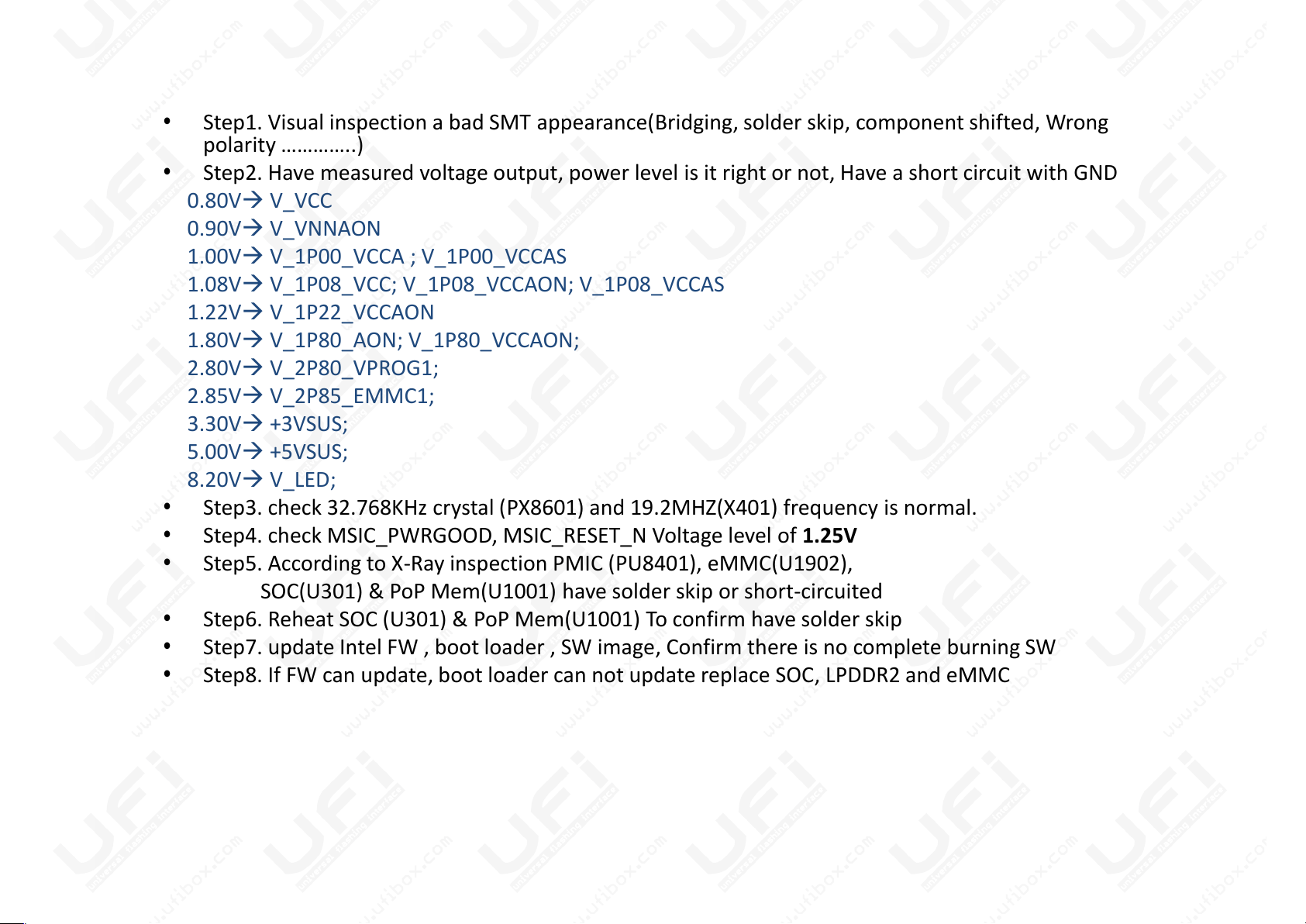
• Step1. Visual inspection a bad SMT appearance(Bridging, solder skip, component shifted, Wrong
polarity …………..)
• Step2. Have measured voltage output, power level is it right or not, Have a short circuit with GND
0.80V V_VCC
0.90V V_VNNAON
1.00V V_1P00_VCCA ; V_1P00_VCCAS
1.08V V_1P08_VCC; V_1P08_VCCAON; V_1P08_VCCAS
1.22V V_1P22_VCCAON
1.80V V_1P80_AON; V_1P80_VCCAON;
2.80V V_2P80_VPROG1;
2.85V V_2P85_EMMC1;
3.30V +3VSUS;
5.00V +5VSUS;
8.20V V_LED;
• Step3. check 32.768KHz crystal (PX8601) and 19.2MHZ(X401) frequency is normal.
• Step4. check MSIC_PWRGOOD, MSIC_RESET_N Voltage level of 1.25V
• Step5. According to X-Ray inspection PMIC (PU8401), eMMC(U1902),
SOC(U301) & PoP Mem(U1001) have solder skip or short-circuited
• Step6. Reheat SOC (U301) & PoP Mem(U1001) To confirm have solder skip
• Step7. update Intel FW , boot loader , SW image, Confirm there is no complete burning SW
• Step8. If FW can update, boot loader can not update replace SOC, LPDDR2 and eMMC

eMMC issue
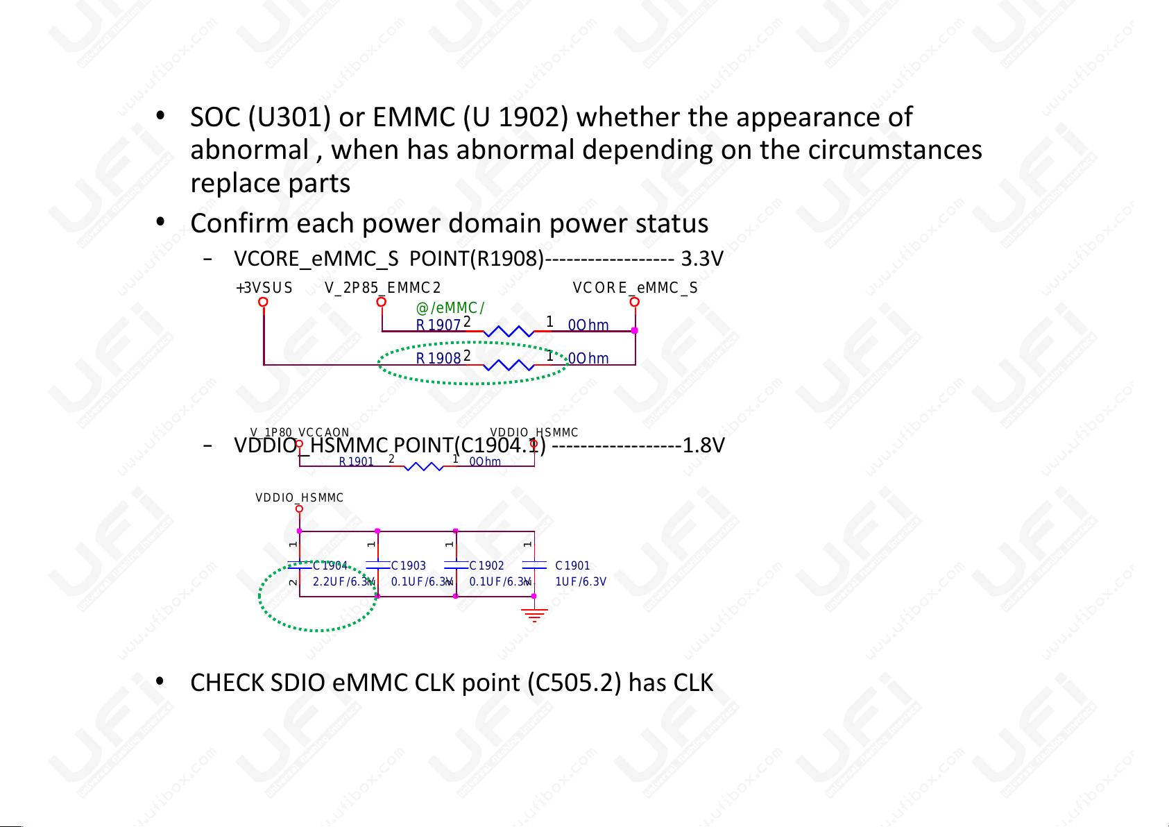
• SOC (U301) or EMMC (U 1902) whether the appearance of
abnormal , when has abnormal depending on the circumstances
replace parts
• Confirm each power domain power status
– VCORE_eMMC_S POINT(R1908)------------------ 3.3V
R1908 0Ohm
12
R1907 0Ohm
@/eMMC/
12
+3VSUS VCORE_eMMC_SV_2P85_EMMC2
• SOC (U301) or EMMC (U 1902) whether the appearance of
abnormal , when has abnormal depending on the circumstances
replace parts
• Confirm each power domain power status
– VCORE_eMMC_S POINT(R1908)------------------ 3.3V
– VDDIO_HSMMC POINT(C1904.1) ------------------1.8V
• CHECK SDIO eMMC CLK point (C505.2) has CLK
C1901
1UF/6.3V
12
R1901 0Ohm
12
C1903
0.1UF/6.3V
12
C1902
0.1UF/6.3V
12
C1904
2.2UF/6.3V
12
V_1P80_VCCAON VDDIO_HSMMC
VDDIO_HSMMC

Display issue
Display issue
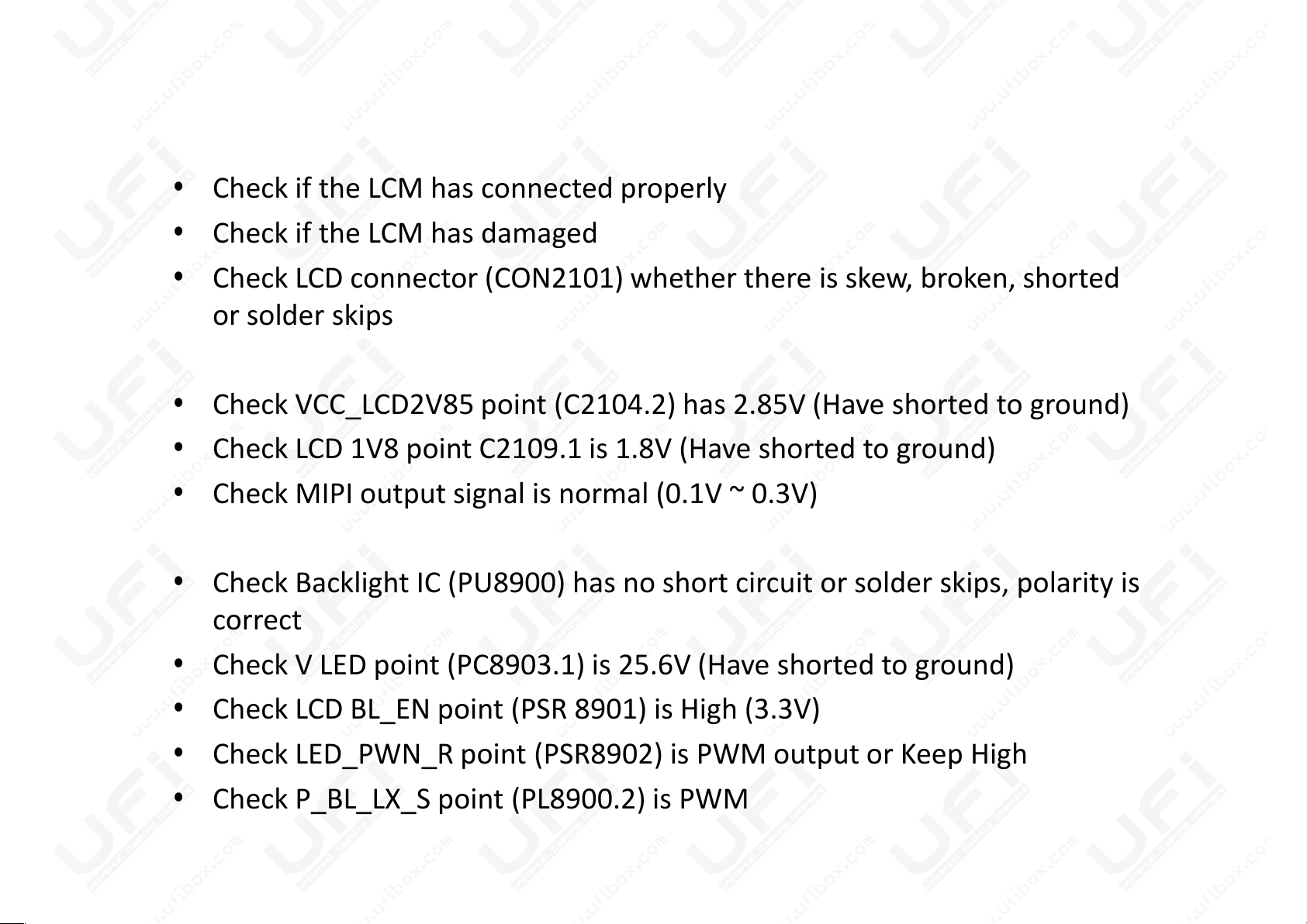
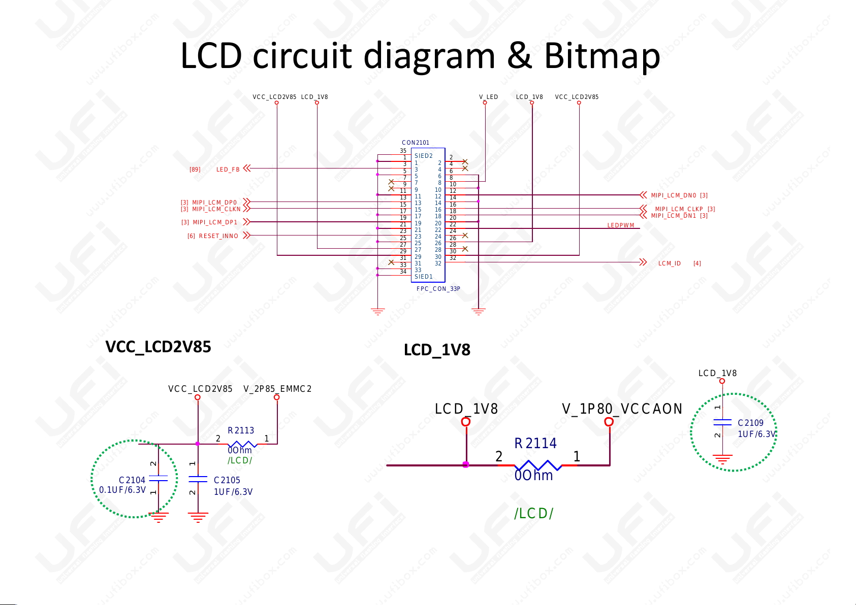
• Check if the LCM has connected properly
• Check if the LCM has damaged
• Check LCD connector (CON2101) whether there is skew, broken, shorted
or solder skips
• Check VCC_LCD2V85 point (C2104.2) has 2.85V (Have shorted to ground)
• Check LCD 1V8 point C2109.1 is 1.8V (Have shorted to ground)
• Check if the LCM has connected properly
• Check if the LCM has damaged
• Check LCD connector (CON2101) whether there is skew, broken, shorted
or solder skips
• Check VCC_LCD2V85 point (C2104.2) has 2.85V (Have shorted to ground)
• Check LCD 1V8 point C2109.1 is 1.8V (Have shorted to ground)
• Check MIPI output signal is normal (0.1V ~ 0.3V)
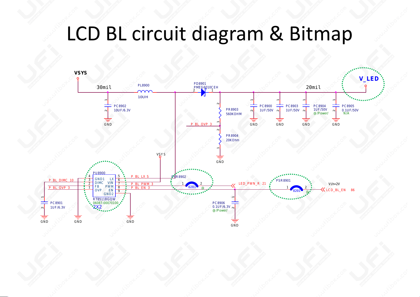
• Check Backlight IC (PU8900) has no short circuit or solder skips, polarity is
correct
• Check V LED point (PC8903.1) is 25.6V (Have shorted to ground)
• Check LCD BL_EN point (PSR 8901) is High (3.3V)
• Check LED_PWN_R point (PSR8902) is PWM output or Keep High
• Check P_BL_LX_S point (PL8900.2) is PWM
LCD circuit diagram & Bitmap
LEDPWM
CON2101
FPC_CON_33P
1
1
2
2
3
3
4
4
5
5
6
6
7
7
8
8
9910
10
111112
12
131314
14
151516
16
171718
18
191920
20
212122
22
232324
24
252526
26
272728
28
292930
30
313132
32
33
33
SIED1
34
SIED2
35
LCD_1V8VCC_LCD2V85 VCC_LCD2V85V_LEDLCD_1V8
MIPI_LCM_CLKN[3]
MIPI_LCM_DP1[3]
MIPI_LCM_DN0 [3]
LCM_ID [4]
LED_FB[89]
RESET_INNO[6]
MIPI_LCM_DN1 [3]
MIPI_LCM_CLKP [3]
MIPI_LCM_DP0[3]
VCC_LCD2V85
C2105
1UF/6.3V
12
V_2P85_EMMC2
R2113
0Ohm
/LCD/
12
C2104
0.1UF/6.3V
1 2
V_1P80_VCCAON
R2114
0Ohm
/LCD/
12
LCD_1V8
VCC_LCD2V85
LCD_1V8
C2109
1UF/6.3V
12
LCD_1V8
LEDPWM
CON2101
FPC_CON_33P
1
1
2
2
3
3
4
4
5
5
6
6
7
7
8
8
9910
10
111112
12
131314
14
151516
16
171718
18
191920
20
212122
22
232324
24
252526
26
272728
28
292930
30
313132
32
33
33
SIED1
34
SIED2
35
LCD_1V8VCC_LCD2V85 VCC_LCD2V85V_LEDLCD_1V8
MIPI_LCM_CLKN[3]
MIPI_LCM_DP1[3]
MIPI_LCM_DN0 [3]
LCM_ID [4]
LED_FB[89]
RESET_INNO[6]
MIPI_LCM_DN1 [3]
MIPI_LCM_CLKP [3]
MIPI_LCM_DP0[3]
LCD BL circuit diagram & Bitmap
P_BL_OVP_3
30mil
20mil
PC8903
1UF/50V
12
PR8903
560KOHM
1 2
PC8904
1UF/50V
@/Power/
12
PC8905
0.1UF/50V
N/A
12
PC8902
10UF/6.3V
12
PL8900
10UH
PR8904
20KOhm
PD8901
PMEG6010CEH
2 1
PC8900
1UF/50V
12
GND
GND
GND
VSYS
V_LED
GND
GND
2X2
Vih=2V
P_BL_EN_3
P_BL_DIMC_10
P_BL_OVP_3
P_BL_LX_S
P_BL_OVP_3
30mil
P_BL_PWM_3
20mil
PC8903
1UF/50V
12
PR8903
560KOHM
1 2
PC8904
1UF/50V
@/Power/
12
PC8905
0.1UF/50V
N/A
12
PC8906
0.1UF/6.3V
@/Power/
12
PU8900
RT8511BGQW
06087-00070100
OVP
1
FB
2
DIMC
3
GND1
4
GND2
9
EN
8
PWM
7
VIN
6
LX
5
PC8902
10UF/6.3V
12
PL8900
10UH
0201
PSR8901
@
21
PC8901
1UF/6.3V
12
PR8904
20KOhm
1 2
0201
PSR8902
@
21
PD8901
PMEG6010CEH
2 1
PC8900
1UF/50V
12
GND
GND
GND
GND
GND
GND
VSYS
V_LED
VSYS
GND
GND
GND
LED_PWN_R 21
LCD_BL_EN 86
GND
 Loading...