


D I S A S S E M B L Y P R O C E D U R E
3Chapter
Disassembly Procedure
Please follow the information provided in this section to perform the complete disassembly procedure of the notebook. Be sure to use proper tools described before.
ASUS A3000N Series Notebook consists of various modules. This chapter describes the procedures for the complete notebook disassembly. In addition, in between procedures, the detailed disassembly procedure of individual modules will be provided for your service needs.
The disassembly procedure consists of the following steps:
•Battery module
•HDD Module
•Memory Module
•Wireless LAN Module
•CPU Module
•ODD-Module
•Keyboard
•LCD Module
•Top Case Module
•Motherboard Module
•Bottom Case Module
3 - 1
B A T T E R Y
B A T T E R Y M O D U L E R E M O V A L
D I S A S S E M B L Y P R O C E D U R E
Battery module
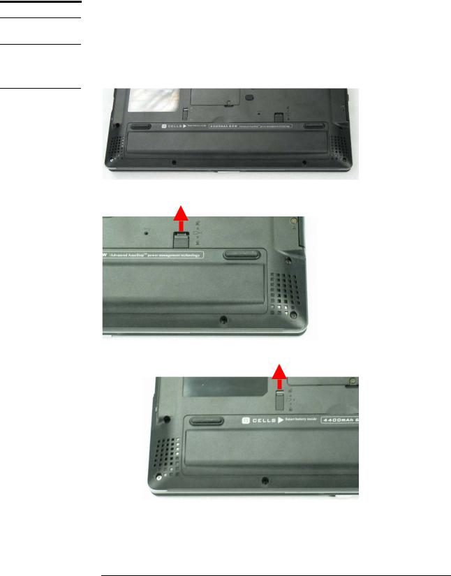
The illustration below shows how to remove the battery module.
Removing Battery Module
1. Turn over the notebook.
2. Slide the battery latch (No.1) to unlock.
1
3. Firmly slide the other latch (No.2) to the top and remove the battery.
2
3 - 2
H D D M O D U L E
H D D M O D U L E
R E M O V A L
D I S A S S E M B L Y P R O C E D U R E
HDD Module
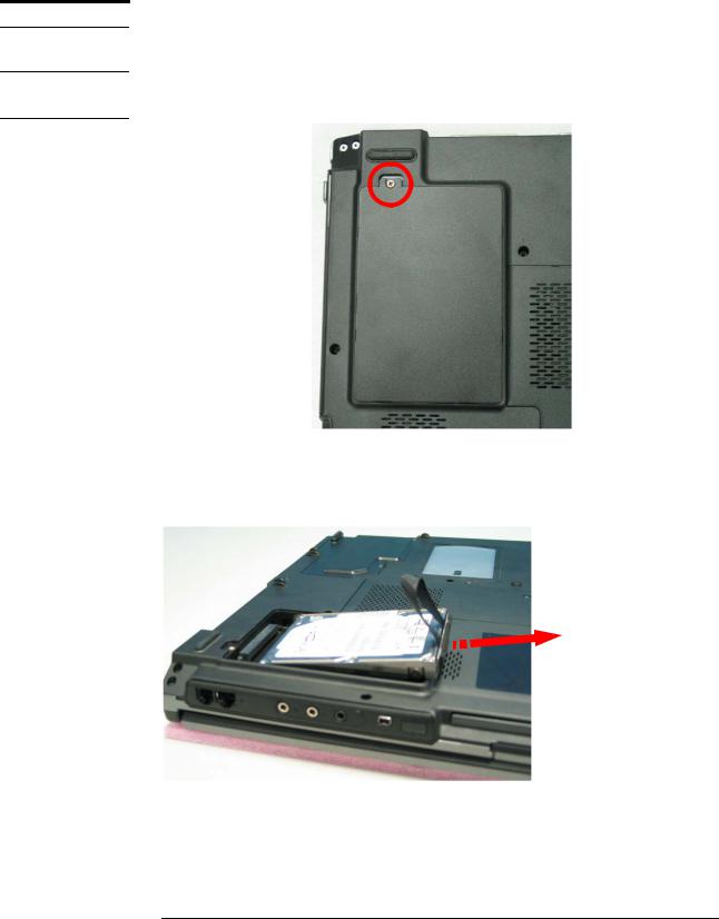
The illustrations below show how to remove the HDD module from the notebook.
Removing HDD Module
1. Release 1 screw (No.1) [M2*4L, (K) B-NI, NY]] from the HDD cover.
1
2.Lift the HDD cover away.
3.Pull out the hard drive and lift the hard drive away by 2 hands.
3 - 3

H D D M O D U L E
D I S A S S E M B L Y
D I S A S S E M B L Y P R O C E D U R E
Disassembling HDD Module
Remove 2 screws here (No.2, No.3) [M3 * 3L (K) B-NI] and 2 screws (No.4, No.5) [M3 * 3 L (K) B-NI] on the other side to separate HDD from HDD housing.
4
5
2
3
*Please do not touch inside of the HDD module.
3 - 4

M E M O R Y M O D U L E
M E M O R Y R E M O V A L
D I S A S S E M B L Y P R O C E D U R E
Memory Module
The A3000N Series Notebook comes standard with one SO-DIMM in SO-DIMM socket. There is another expansion SO-DIMM socket for you to upgrade the total memory up to 1024MB with two 512MB SO-DIMM.
Removing Memory module
1.Remove 2 screws on DDR Door (No.1, No.2) [M2*3L(K, D3.4) W-NI NY]
1
2
2.Lift the DDR Door away
3.Open the 2 latches aside (No. 3, 4), which will pop the memory module up to an angle of 30°, then pull out the memory module in that angle (No. 5).
 3
3
5
30o
 4
4
3 - 5

W I R E L E S S
L A N
W I R E L E S S
L A N
R E M O V A L
D I S A S S E M B L Y P R O C E D U R E
Wireless LAN Module
The illustration below shows how to remove the Wireless LAN module.
Removing Wireless LAN module
1. Remove 2 Antenna cables from Wireless LAN Module. (No.1, No.2) (White cable: AUX, Black cable: MAIN)
1 2
2.Remove the Wireless LAN module by opening the 2 latches aside, which will pop the module up to an angle of 30°, then pull out the module in that angle just like memory module.
 30o
30o
3 - 6

C P U
C P U
R E M O V A L
D I S A S S E M B L Y P R O C E D U R E
CPU Module
The illustrations below show how to remove the CPU module from the notebook.
Removing CPU
1.Remove 2 screws on the Thermal Door, (No.1, No.2) [M2*4L, (K) B-NI, NY].
2
1
2.Lift the Thermal Door away.
3 - 7
D I S A S S E M B L Y P R O C E D U R E
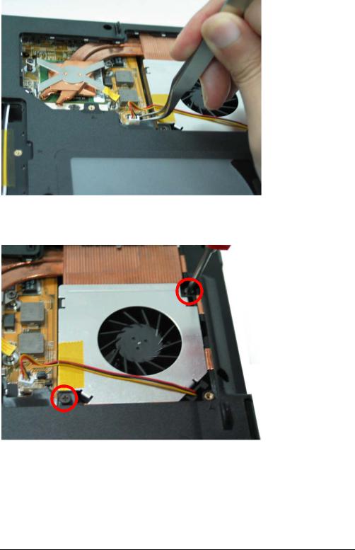
3.Disconnect the cable on CPU module.
4.Remove the 2 screws aside the CPU fan (No.3, No.4) [M2 * 6L (K, D4.6) (K) B- NI, NY].
3
4
5.Lift the CPU FAN module away.
3 - 8

D I S A S S E M B L Y P R O C E D U R E
6.Remove the 4 screws upon the CPU module (No.5 ~No.8) [M2 * 6L (K, D4.6)
(K) B-NI, NY].
6 |
|
|
8 |
7 |
5 |
|
7.Take away the CPU heat sink module gently.
3 - 9
 Loading...