

Page 1

DISASSEMBLY PROCEDURE
A
Disassembly Procedure
Please follow the information provided in this section to perform
the complete disassembly procedure of the notebook. Be sure to
use proper tools described before.
SUS A3000N Series Notebook consists of various modules. This chapter
describes the procedures for the complete notebook disassembly. In
addition, in between procedures, the detailed disassembly procedure of
individual modules will be provided for your service needs.
Chapter
The disassembly procedure consists of the following steps:
• Battery module
• HDD Module
• Memory Module
• Wireless LAN Module
• CPU Module
• ODD-Module
• Keyboard
• LCD Module
• Top Case Module
• Motherboard Module
• Bottom Case Module
3 - 1
Page 2
DISASSEMBLY PROCEDURE
BATTERY
BATTERY
MODULE
REMOVAL
Battery module
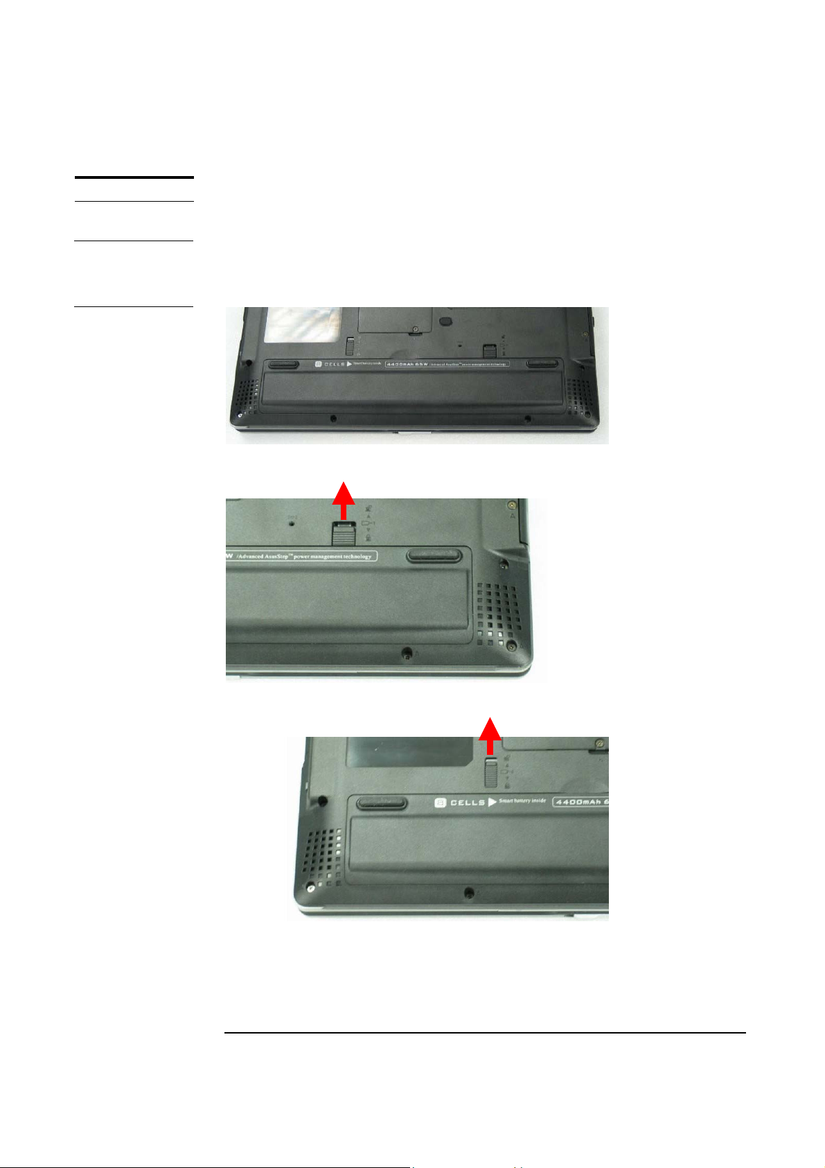
The illustration below shows how to remove the battery module.
Removing Battery Module
1. Turn over the notebook.
2. Slide the battery latch (No.1) to unlock.
1
3. Firmly slide the other latch (No.2) to the top and remove the battery.
2
3 - 2
Page 3

DISASSEMBLY PROCEDURE
HDD MODULE
HDD MODULE
REMOVAL
HDD Module
The illustrations below show how to remove the HDD module from the notebook.
Removing HDD Module
1. Release 1 screw (No.1) [M2*4L, (K) B-NI, NY]] from the HDD cover.
1
2. Lift the HDD cover away.
3. Pull out the hard drive and lift the hard drive away by 2 hands.
3 - 3
Page 4
HDD MODULE
DISASSEMBLY
DISASSEMBLY PROCEDURE
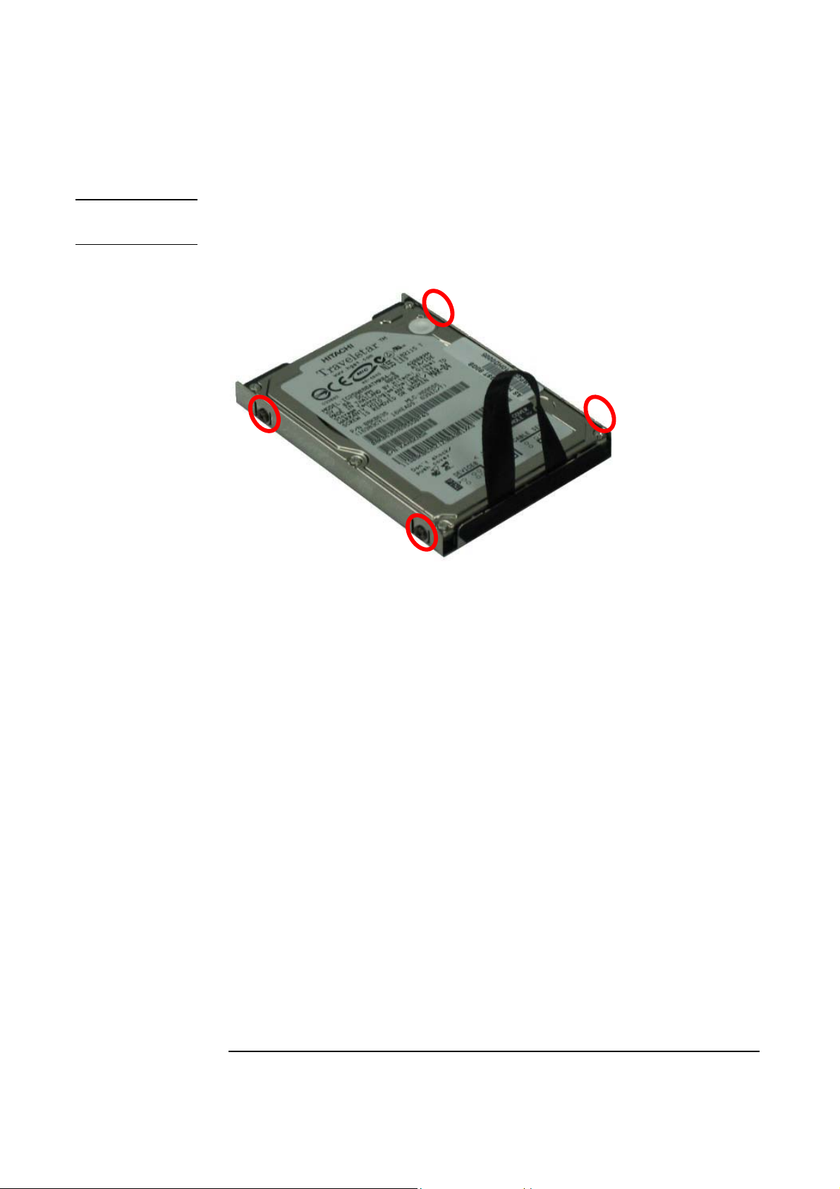
Disassembling HDD Module
Remove 2 screws here (No.2, No.3) [M3 * 3L (K) B-NI] and 2 screws (No.4, No.5)
[M3 * 3 L (K) B-NI] on the other side to separate HDD from HDD housing.
4
5
2
3
*Please do not touch inside of the HDD module.
3 - 4
Page 5
DISASSEMBLY PROCEDURE
MEMORY
MODULE
MEMORY
REMOVAL
Memory Module
The A3000N Series Notebook comes standard with one SO-DIMM in SO-DIMM
socket. There is another expansion SO-DIMM socket for you to upgrade the total
memory up to 1024MB with two 512MB SO-DIMM.
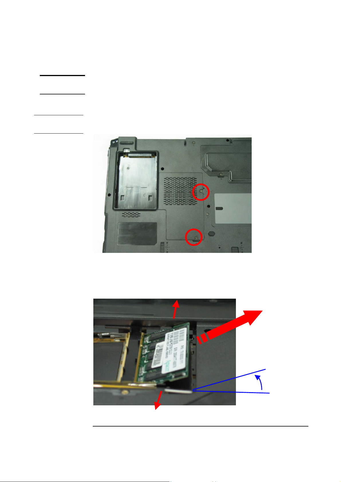
Removing Memory module
1. Remove 2 screws on DDR Door (No.1, No.2) [M2*3L(K, D3.4) W-NI NY]
1
2
2. Lift the DDR Door away
3. Open the 2 latches aside (No. 3, 4), which will pop the memory module up to an
angle of 30°, then pull out the memory module in that angle (No. 5).
3
5
30o
4
3 - 5
Page 6
DISASSEMBLY PROCEDURE
WIRELESS
LAN
WIRELESS
LAN
REMOVAL
Wireless LAN Module
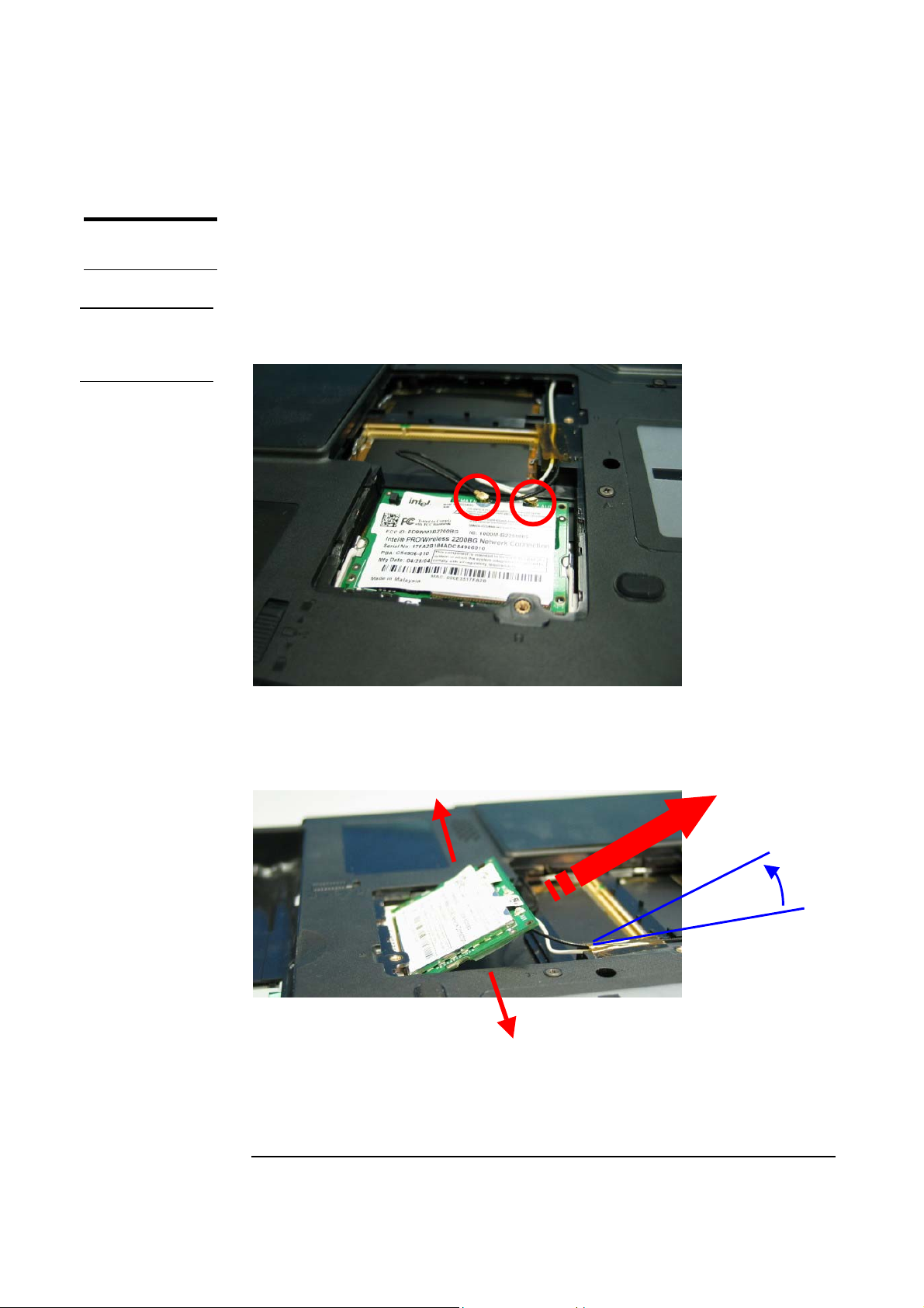
The illustration below shows how to remove the Wireless LAN module.
Removing Wireless LAN module
1. Remove 2 Antenna cables from Wireless LAN Module. (No.1, No.2)
(White cable: AUX, Black cable: MAIN)
1
2
2. Remove the Wireless LAN module by opening the 2 latches aside, which will pop
the module up to an angle of 30°, then pull out the module in that angle just like
memory module.
30o
3 - 6
Page 7
DISASSEMBLY PROCEDURE
CPU
CPU
REMOVAL
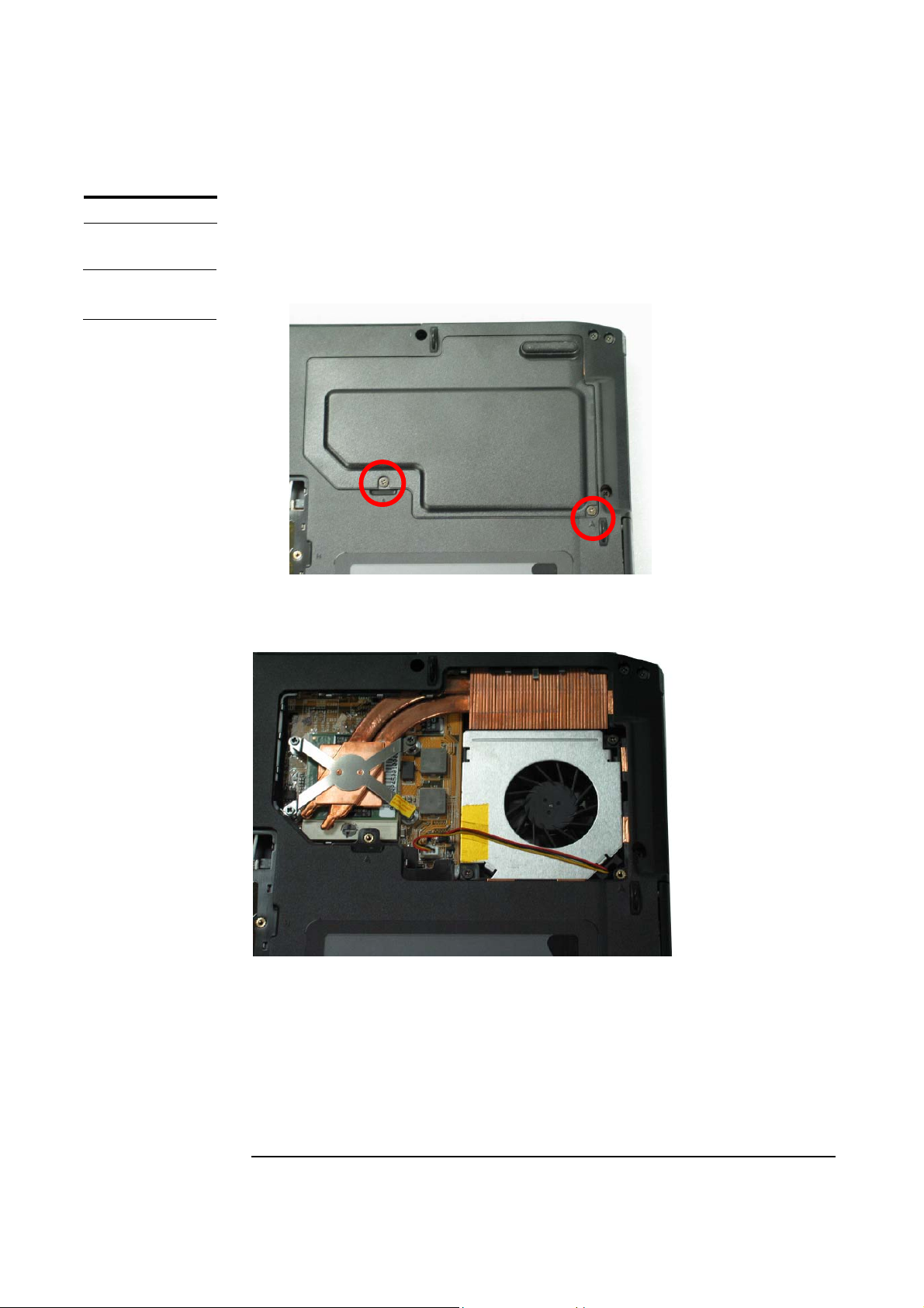
CPU Module
The illustrations below show how to remove the CPU module from the notebook.
Removing CPU
1. Remove 2 screws on the Thermal Door, (No.1, No.2) [M2*4L, (K) B-NI, NY].
2
1
2. Lift the Thermal Door away.
3 - 7
Page 8
DISASSEMBLY PROCEDURE
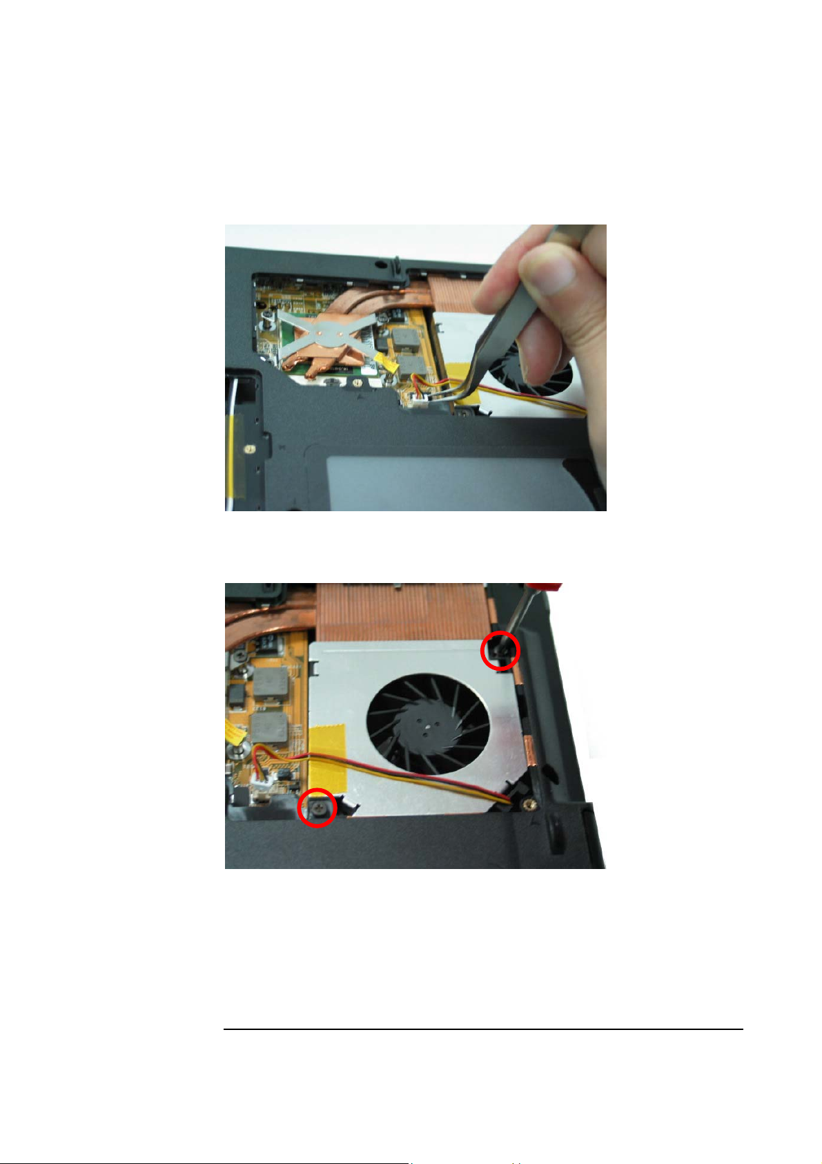
3. Disconnect the cable on CPU module.
4. Remove the 2 screws aside the CPU fan (No.3, No.4) [M2 * 6L (K, D4.6) (K) B-
NI, NY].
4
5. Lift the CPU FAN module away.
3 - 8
3
Page 9
DISASSEMBLY PROCEDURE
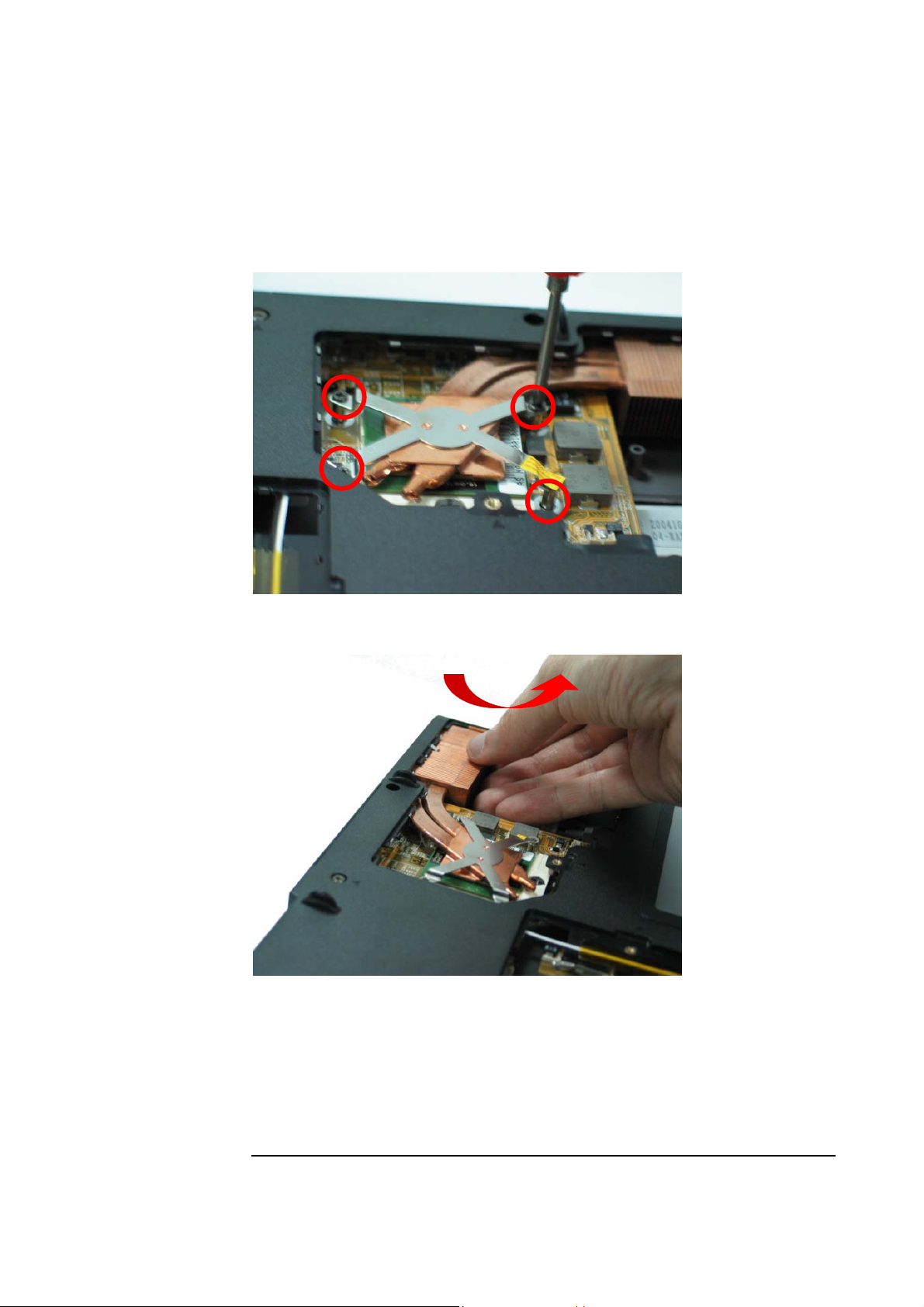
6. Remove the 4 screws upon the CPU module (No.5 ~No.8) [M2 * 6L (K, D4.6)
(K) B-NI, NY].
6
8
7
5
7. Take away the CPU heat sink module gently.
3 - 9
Page 10

DISASSEMBLY PROCEDURE
8. Turn the non-removable screw here 180 degrees counter-clockwise to loosen the
CPU.
L
O
Unlock
9. Squeeze the vacuum handling pump and use it to lift the CPU away.
* Don’t touch the die above the CPU.
3 - 10
Page 11

DISASSEMBLY PROCEDURE
ODD MODULE
ODD
REMOVAL
ODD Module
The illustration below shows how to remove the ODD module.
1. Remove 2 screws from the cover (No.1, No.2) [M2 * 4L (K) B-NI, NY].
1
2
2. Put the screwdriver (No. 3) here and push the ODD drive out from the NB.
3
3 - 11
Page 12

DISASSEMBLY PROCEDURE
3. Remove 4 screws (no.4-7) [M2 * 2L (P) W-NI] from ODD bracket.
7
4
5
6
3 - 12
Page 13

DISASSEMBLY PROCEDURE
KEYBOARD
DISASSEMBLY
KEYBOARD
REMOVAL
Keyboard
The illustration below shows how to remove the keyboard
Removing Keyboard
1. Remove 2 screws here (No.1, No.2) [M2 * 6L (K, D4.6) (K) B-NI, NY]
1
2
2. Turn over the NB and open the display panel.
3. Push the 3 latches in (No.1, No.2, No.3) with a pair of tweezers or a singleslotted screwdriver and lift the keyboard plate up.
2
1
3
3 - 13
Page 14

CABLE
REMOVAL
DISASSEMBLY PROCEDURE
4. Lay the keyboard down over the Touch Pad module.
keyboard yet.
The keyboard cable is still attached.
*Do not remove the
Removing Keyboard Cable
1. Use a flexible connector tool to unlock the cable connector on both ends (no. 1).
2. Carefully pull out the keyboard cable (no. 2) with a pair of tweezers.
3. Lock the connector (no. 3) again to avoid possible breakage.
2. Cable out
1. Unlock
3. Lock
1. Unlock
3. Lock
4. Remove keyboard from the top case.
3 - 14
Page 15

DISASSEMBLY PROCEDURE
5. Disconnect the connector of touch pad beneath keyboard.
3 - 15
Page 16

DISASSEMBLY PROCEDURE
LCD
LCD
REMOVAL
LCD Module
The illustrations below show how to remove and disassemble the LCD module. The
module contains LCD panel, invert, LCD hinge bracket, hinge cover, LCD front cover
and LCD bottom case.
Removing LCD Module
1. Close the display panel.
2. Remove 2 screws on the harness cover (No.1, No.2). [M2 * 4L(K) B-NI, NY]
Please do not disassemble the individual parts.
1
2
3. Remove the harness cover.
4. Remove 2 screws here (No.3). [M2 * 4L (K) B-NI, NY], (No.4). [M2 * 6L (K,
D4.6) (K) B-NI, NY]
3
4
3 - 16
Page 17

DISASSEMBLY PROCEDURE
5. Disconnect the 2 connectors.
6. Open LCD, and remove 2 screws on both ends (No.1, No.2). [M2. * 4L]
1
7. Remove 4 screws on both ends (No.3-6). [M2 * 6L]
3
5
8. Remove the LCD module from system.
6
2
4
3 - 17
Page 18

LCD DIS-
ASSEMBLY
DISASSEMBLY PROCEDURE
Disassembling LCD Module
1. Remove 5 rubes and 5 screws (No.1 ~ No.5) [M2.5*6L(K) (4.6) B-NI, NY] on the
LCD bezel.
4
5
3
1
2
2. Carefully pry the inside edges of the LCD case open on all four edges with your
fingers. Then, lift it away from the LCD module.
3 - 18
Page 19

DISASSEMBLY PROCEDURE
12
3. Disconnect the 2 cables on inverter board. (No.7, No.8).
7
8
4. Remove 4 screws here (no.9-12) [M2.5*6L(K) (4.6) B-NI, NY].
9
10
11
3 - 19
Page 20

DISASSEMBLY PROCEDURE
15 14 13
5. Remove 4 screws (no.13-16) [M2*3L(K) B-NI, NYLOK] to separate the LCD
panel from the LCD back cover.
16
6. Remove the panel and the 2 hinge modules from the LCD back cover.
3 - 20
Page 21

DISASSEMBLY PROCEDURE
21 19 22 20
7. Remove 6 screws (no.17-22) [M2*3L(K) B-NI, NYLOK] on both sides to
separate the LCD brackets from the panel.
18
17
8. Disconnect the cable on the back of LCD panel.
3 - 21
Page 22

DISASSEMBLY PROCEDURE
9. Tear of the tape and disconnect the cable from CCD module.
10. Remove CCD module.
3 - 22
Page 23

DISASSEMBLY PROCEDURE
11. Tear the tape on aluminum foil and Remove the cable and microphone.
3 - 23
Page 24

DISASSEMBLY PROCEDURE
TOP CASE
MODULE
TOP CASE
MODULE
REMOVE
Top Case Module
The illustrations below show how to disassemble and remove the top case module of
the notebook. The module contains the top case itself, touch pad module.
Removing Top Case Module
1. Remove 2 screws (no.1, no.2) [M2*4L(K) B-NI] at back side of notebook.
1
2. Remove 3 screws here (no.3-5) [M2*3L]
2
3
3 - 24
5 4
Page 25

DISASSEMBLY PROCEDURE
12
13 15
3. Remove 5 screws here (no.6-10) [M2*4L].
10
6
8
4. Remove 5 screws here (no.11-15) [M2*6L]
11
9
7
14
3 - 25
Page 26

DISASSEMBLY PROCEDURE
17 19 18 20 21
5. Lift it up to release the top case.
TOUCH PAD
MODULE
REMOVE
Removing Touch Pad Module
1. Remove 6 screws here (No.16-21) [M2 * 3L]
16
2. Disconnect the FPC cable and then remove the touchpad module.
3 - 26
Page 27

DISASSEMBLY PROCEDURE
MOTHERBOARD
MODEM CARD
REMOVAL
Motherboard Module
The illustrations below show how to disassemble and remove the motherboard
module of the notebook. The module contains the motherboard itself, modem card
module.
Removing Modem card
1. Remove 2 screws (no.1-2) (M2*2.5L (K) W-NI)on the modem card.
2
1
2. Pull out the modem card from motherboard.
3. Remove the tape and disconnect the cables (no.3) from modem card and
motherboard.
3
3 - 27
Page 28

MOTHERBOARD
REMOVAL
DISASSEMBLY PROCEDURE
Removing Motherboard
1. Disconnect the connector of speaker (no.4) on motherboard.
4
2. Remove 5 screws (no.5-9)(M2*4L)on motherboard.
5
6
9
8
7
3 - 28
Page 29

30o
DISASSEMBLY PROCEDURE
3. Lift the motherboard up a little bit and push aside the bottom case, and then
separate motherboard module from the bottom case at an angle of 20 degree.
3 - 29
Page 30

DISASSEMBLY PROCEDURE
BOTTOM
CASE
MODULE
SPEAKERS
REMOVAL
Bottom Case Module
The illustrations below show how to disassemble and remove the bottom case module
of the notebook. The module contains the bottom case itself and speakers.
Removing Speakers
1. Remove the 4 screws (no.1-4)(M2*3L)on both ends.
1
2
3
4
4. Lift up both speakers and speaker cable away from the bottom case.
3 - 30
 Loading...