

Asus 990FXGEN3, 990FX R20, 990FX-GEN3 R2 User Manual

SABERTOOTH
990FX/GEN3
R2.0
Motherboard

E8041
Revised Edition V2
January 2013
Copyright © 2013 ASUSTeK COMPUTER INC. All Rights Reserved.
No part of this manual, including the products and software described in it, may be reproduced,
transmitted, transcribed, stored in a retrieval system, or translated into any language in any form or by any
means, except documentation kept by the purchaser for backup purposes, without the express written
permission of ASUSTeK COMPUTER INC. (“ASUS”).
Product warranty or service will not be extended if: (1) the product is repaired, modied or altered, unless
such repair, modication of alteration is authorized in writing by ASUS; or (2) the serial number of the
product is defaced or missing.
ASUS PROVIDES THIS MANUAL “AS IS” WITHOUT WARRANTY OF ANY KIND, EITHER EXPRESS
OR IMPLIED, INCLUDING BUT NOT LIMITED TO THE IMPLIED WARRANTIES OR CONDITIONS OF
MERCHANTABILITY OR FITNESS FOR A PARTICULAR PURPOSE. IN NO EVENT SHALL ASUS, ITS
DIRECTORS, OFFICERS, EMPLOYEES OR AGENTS BE LIABLE FOR ANY INDIRECT, SPECIAL,
INCIDENTAL, OR CONSEQUENTIAL DAMAGES (INCLUDING DAMAGES FOR LOSS OF PROFITS,
LOSS OF BUSINESS, LOSS OF USE OR DATA, INTERRUPTION OF BUSINESS AND THE LIKE),
EVEN IF ASUS HAS BEEN ADVISED OF THE POSSIBILITY OF SUCH DAMAGES ARISING FROM ANY
DEFECT OR ERROR IN THIS MANUAL OR PRODUCT.
SPECIFICATIONS AND INFORMATION CONTAINED IN THIS MANUAL ARE FURNISHED FOR
INFORMATIONAL USE ONLY, AND ARE SUBJECT TO CHANGE AT ANY TIME WITHOUT NOTICE,
AND SHOULD NOT BE CONSTRUED AS A COMMITMENT BY ASUS. ASUS ASSUMES NO
RESPONSIBILITY OR LIABILITY FOR ANY ERRORS OR INACCURACIES THAT MAY APPEAR IN THIS
MANUAL, INCLUDING THE PRODUCTS AND SOFTWARE DESCRIBED IN IT.
Products and corporate names appearing in this manual may or may not be registered trademarks or
copyrights of their respective companies, and are used only for identication or explanation and to the
owners’ benet, without intent to infringe.
Offer to Provide Source Code of Certain Software
This product contains copyrighted software that is licensed under the General Public License (“GPL”),
under the Lesser General Public License Version (“LGPL”) and/or other Free Open Source Software
Licenses. Such software in this product is distributed without any warranty to the extent permitted by the
applicable law. Copies of these licenses are included in this product.
Where the applicable license entitles you to the source code of such software and/or other additional data,
you may obtain it for a period of three years after our last shipment of the product, either
(1) for free by downloading it from http://support.asus.com/download
or
(2) for the cost of reproduction and shipment, which is dependent on the preferred carrier and the location
where you want to have it shipped to, by sending a request to:
ASUSTeK Computer Inc.
Legal Compliance Dept.
15 Li Te Rd.,
Beitou, Taipei 112
Taiwan
In your request please provide the name, model number and version, as stated in the About Box of the
product for which you wish to obtain the corresponding source code and your contact details so that we
can coordinate the terms and cost of shipment with you.
The source code will be distributed WITHOUT ANY WARRANTY and licensed under the same license as
the corresponding binary/object code.
This offer is valid to anyone in receipt of this information.
ASUSTeK is eager to duly provide complete source code as required under various Free Open Source
Software licenses. If however you encounter any problems in obtaining the full corresponding source
code we would be much obliged if you give us a notication to the email address gpl@asus.com, stating
the product and describing the problem (please DO NOT send large attachments such as source code
archives, etc. to this email address).
ii

Contents
Safety information ..................................................................................................... vii
About this guide ....................................................................................................... viii
SABERTOOTH 990FX/GEN3 R2.0 specications summary .................................... x
Package contents ..................................................................................................... xiii
Installation tools and components ......................................................................... xiv
Chapter 1: Product Introduction 1-1
1.1 Special features..........................................................................................1-1
1.1.1 Product highlights........................................................................1-1
1.1.2 “Ultimate COOL!” Thermal Solution ............................................ 1-2
1.1.3 “TUF ENGINE!” Power Design....................................................1-2
1.1.4 “Safe & Stable!” Guardian Angel ................................................. 1-3
1.1.5 ASUS EZ DIY ..............................................................................1-3
1.1.6 Other special features ................................................................. 1-4
1.2 Motherboard overview ............................................................................... 1-5
1.2.1 Before you proceed .....................................................................1-5
1.2.2 Motherboard layout ..................................................................... 1-6
1.2.3 Central Processing Unit (CPU) ...................................................1-8
1.2.4 System memory .......................................................................... 1-9
1.2.5 Expansion slots ......................................................................... 1-23
1.2.6 Onboard buttons .......................................................................1-25
1.2.7 Jumpers ....................................................................................1-27
1.2.8 Onboard LEDs ..........................................................................1-28
1.2.9 Internal connectors....................................................................1-29
Chapter 2: Basic Installation 2-1
2.1 Building your PC system...........................................................................2-1
2.1.1 Motherboard installation ..............................................................2-1
2.1.2 CPU installation...........................................................................2-4
2.1.3 CPU heatsink and fan assembly installation ............................... 2-5
2.1.4 DIMM installation.........................................................................2-7
2.1.5 ATX Power connection ................................................................ 2-8
2.1.6 SATA device connection ..............................................................2-9
2.1.7 Front I/O Connector ..................................................................2-10
2.1.8 Expansion Card installation....................................................... 2-11
2.2 BIOS update utility ................................................................................... 2-12
2.3 Motherboard rear and audio connections .............................................2-13
iii

2.3.1 Rear I/O connection .................................................................. 2-13
2.3.2 Audio I/O connections ............................................................... 2-15
2.4 Starting up for the rst time .................................................................... 2-17
2.5 Turning off the computer ......................................................................... 2-18
Chapter 3: BIOS setup 3-1
3.1 Knowing BIOS ............................................................................................3-1
3.2 BIOS setup program ..................................................................................3-2
3.2.1 EZ Mode......................................................................................3-3
3.2.2 Advanced Mode .......................................................................... 3-4
3.3 Main menu ..................................................................................................3-6
3.4 Ai Tweaker menu ........................................................................................ 3-8
3.5 Advanced menu .......................................................................................3-17
3.5.1 CPU Conguration .................................................................... 3-17
3.5.2 North Bridge Conguration........................................................3-19
3.5.3 South Bridge Conguration ....................................................... 3-21
3.5.4 SATA Conguration ................................................................... 3-21
3.5.5 USB Conguration ....................................................................3-23
3.5.6 CPU Core On/Off Function .......................................................3-24
3.5.7 Onboard Devices Conguration ................................................ 3-24
3.5.8 APM ..........................................................................................3-26
3.5.9 Network Stack ........................................................................... 3-27
3.6 Monitor menu ...........................................................................................3-28
3.7 Boot menu ................................................................................................3-31
3.8 Tools menu ............................................................................................... 3-37
3.8.1 ASUS EZ Flash 2 Utility ............................................................ 3-37
3.8.2 ASUS SPD Information ............................................................. 3-38
3.8.3 ASUS O.C. Prole ..................................................................... 3-39
3.9 Exit menu .................................................................................................. 3-40
3.10 Updating BIOS .......................................................................................... 3-41
3.10.1 ASUS Update ............................................................................ 3-41
3.10.2 ASUS EZ Flash 2 ...................................................................... 3-44
3.10.3 ASUS BIOS Updater ................................................................. 3-45
Chapter 4: Software support 4-1
4.1 Installing an operating system .................................................................4-1
4.2 Support DVD information .......................................................................... 4-1
iv

4.2.1 Running the support DVD ........................................................... 4-1
4.2.2 Obtaining the software manuals..................................................4-2
4.3 Software information .................................................................................4-3
4.3.1 AI Suite II.....................................................................................4-3
4.3.2 ASUS TUF Thermal Radar .........................................................4-4
4.3.3 Remote GO! ................................................................................ 4-8
4.3.4 TurboV EVO .............................................................................. 4-19
4.3.5 DIGI+ Power Control .................................................................4-22
4.3.6 Sensor Recorder ....................................................................... 4-25
4.3.7 Ai Charger+ ...............................................................................4-27
4.3.8 USB 3.0 Boost...........................................................................4-28
4.3.9 USB BIOS Flashback Wizard....................................................4-29
4.3.10 Network iControl........................................................................4-31
4.3.11 ASUS Update ............................................................................ 4-36
4.3.12 MyLogo2 ...................................................................................4-37
4.3.13 Audio congurations..................................................................4-38
Chapter 5: RAID support 5-1
5.1 RAID congurations ..................................................................................5-1
5.1.1 RAID denitions ..........................................................................5-1
5.1.2 Installing Serial ATA hard disks ...................................................5-2
5.1.3 Setting the RAID item in BIOS .................................................... 5-2
5.1.4 AMD® Option ROM Utility ............................................................ 5-3
5.2 Creating a RAID driver disk.......................................................................5-7
5.2.1 Creating a RAID driver disk without entering the OS .................. 5-7
5.2.2 Creating a RAID driver disk in Windows® .................................... 5-7
5.2.3 Installing the RAID driver during Windows® OS installation ........ 5-8
5.2.4 Using a USB oppy disk drive ..................................................... 5-9
Chapter 6: Multiple GPU support 6-1
6.1 AMD® CrossFireX™ technology ...............................................................6-1
6.1.1 Requirements .............................................................................. 6-1
6.1.2 Before you begin ......................................................................... 6-1
6.1.3 Installing two CrossFireX™ graphics cards ................................6-2
6.1.4 Installing the device drivers ......................................................... 6-4
6.1.5 Enabling the AMD® CrossFireX™ technology ............................. 6-4
6.2 NVIDIA® SLI™ technology ......................................................................... 6-6
v

6.2.1 Requirements .............................................................................. 6-6
6.2.2 Installing two SLI-ready graphics cards ......................................6-6
6.2.3 Installing the device drivers ......................................................... 6-7
6.2.4 Enabling the NVIDIA® SLI™ technology ..................................... 6-8
Appendices A-1
Notices .................................................................................................................... A-1
ASUS contact information ...................................................................................... A-4
vi

Safety information
Electrical safety
To prevent electrical shock hazard, disconnect the power cable from the electrical outlet
•
before relocating the system.
When adding or removing devices to or from the system, ensure that the power cables
•
for the devices are unplugged before the signal cables are connected. If possible,
disconnect all power cables from the existing system before you add a device.
Before connecting or removing signal cables from the motherboard, ensure that all
•
power cables are unplugged.
Seek professional assistance before using an adapter or extension cord. These devices
•
could interrupt the grounding circuit.
Ensure that your power supply is set to the correct voltage in your area. If you are not
•
sure about the voltage of the electrical outlet you are using, contact your local power
company.
If the power supply is broken, do not try to x it by yourself. Contact a qualied service
•
technician or your retailer.
Operation safety
Before installing the motherboard and adding devices on it, carefully read all the manuals
•
that came with the package.
Before using the product, ensure all cables are correctly connected and the power
•
cables are not damaged. If you detect any damage, contact your dealer immediately.
To avoid short circuits, keep paper clips, screws, and staples away from connectors,
•
slots, sockets and circuitry.
Avoid dust, humidity, and temperature extremes. Do not place the product in any area
•
where it may become wet.
Place the product on a stable surface.
•
If you encounter technical problems with the product, contact a qualied service
•
technician or your retailer.
vii

About this guide
This user guide contains the information you need when installing and conguring the
motherboard.
How this guide is organized
This guide contains the following parts:
• Chapter 1: Product introduction
This chapter describes the features of the motherboard and the new technology it
supports. It includes description of the switches, jumpers, and connectors on the
motherboard.
• Chapter 2: Basic Installation
This chapter lists the hardware setup procedures that you have to perform when
installing system components.
• Chapter 3: BIOS setup
This chapter tells how to change system settings through the BIOS Setup menus.
Detailed descriptions of the BIOS parameters are also provided.
• Chapter 4: Software support
This chapter describes the contents of the support DVD that comes with the
motherboard package and the software.
• Chapter 5: RAID support
This chapter describes the RAID congurations.
• Chapter 6: Multiple GPU technology support
This chapter describes how to install and congure multiple AMD® CrossFireX™ and
NVIDIA® SLI™ graphics cards.
Where to nd more information
Refer to the following sources for additional information and for product and software
updates.
1. ASUS websites
The ASUS website provides updated information on ASUS hardware and software
products. Refer to the ASUS contact information.
2. Optional documentation
Your product package may include optional documentation, such as warranty yers,
that may have been added by your dealer. These documents are not part of the
standard package.
viii

Conventions used in this guide
To ensure that you perform certain tasks properly, take note of the following symbols used
throughout this manual.
DANGER/WARNING: Information to prevent injury to yourself when trying to
complete a task.
CAUTION: Information to prevent damage to the components when trying to
complete a task
IMPORTANT: Instructions that you MUST follow to complete a task. .
NOTE: Tips and additional information to help you complete a task.
Typography
Bold text Indicates a menu or an item to select.
Italics
<Key> Keys enclosed in the less-than and greater-than sign
<Key1> + <Key2> + <Key3> If you must press two or more keys simultaneously, the key
Used to emphasize a word or a phrase.
means that you must press the enclosed key.
Example: <Enter> means that you must press the Enter or
Return key.
names are linked with a plus sign (+).
ix
SABERTOOTH 990FX/GEN3 R2.0 specications summary
CPU AMD® Socket AM3+ for AMD® FX series CPU up to 8-core
compatible with AMD® Socket AM3 for AMD® Phenom™ II /
Athlon II™ / Sempron™ 100 series processors
Supports AMD® 140W CPU
AMD® Cool ‘n’ Quiet Technology
Supports 32nm CPU
Chipset AMD® 990FX / SB950 Chipset
System Bus Up to 5.2 GT/s HyperTransport™ 3.0
Memory 4 x DIMM, max. 32GB, DDR3 1866 / 1600 / 1333 / 1066 MHz, ECC,
non-ECC, un-buffered memory
Dual channel memory architecture
* Refer to www.asus.com for Memory QVL (Qualied Vendors List) of
AM3+ / AM3 CPU for details.
** Due to OS limitation, when installing a total memory of 4GB capacity
or more, Windows® 32-bit operation system may only recognize
less than 3GB. Hence, a total installed memory of less than 3GB is
recommended.
*** Due to CPU specications, AMD 100 Series CPUs support up to DDR3
1066MHz. With ASUS design, this motherboard can support up to
DDR3 1333MHz.
Expansion slots 3 x PCI Express 3.0 x16 slots (Dual at x16/x16, triple at x16/x8/x8
mode)*
1 x PCI Express 2.0 x16 slot (black@x16)
1 x PCI slot
* When running dual graphics cards, ensure to insert the card in the rst
and third PCI Express X16 slot to get the best performance.
Multi-GPU support Supports NVIDIA® QUAD-GPU SLI™ Technology
Supports AMD® QUAD-GPU CrossFireX™ Technology
LAN Realtek® 8111F Gigabit LAN controller
Storage
AMD® SB950 Chipset
- 6 x SATA 6.0 Gb/s ports with RAID 0, 1, 5 and 10 support
ASMedia® SATA 6Gb/s controllers
- 2 x SATA 6Gb/s ports
- 2 x eSATA 6Gb/s ports [red]
Audio
Realtek® ALC892 8-channel high denition audio
CODEC
- Absolute Pitch 192khz/24bit True BD Lossless Sound
- BD audio layer content protection
- Supports jack-detection, multi-streaming and front panel jackretasking
- Optical S/PDIF out ports at back I/O
- ASUS noise lter
(continued on the next page)
x

SABERTOOTH 990FX/GEN3 R2.0 specications summary
USB
3 x ASMedia® USB 3.0 controllers
- 2 x USB 3.0/2.0 ports at mid-board for front panel support
- 4 x USB 3.0/2.0 ports at back panel [blue]
AMD® SB950 Chipset
- 12 x USB 2.0/1.1 ports (4 ports at mid-board, 8 ports at back
panel)
Exclusive TUF features
“Ultimate COOL” Thermal Solution
- TUF CeraM!X heatsink coating technology
- TUF Thermal radar
TUF ENGINE! Digital Power Design
- 8+2 Digital phase power design
- TUF Components (alloy choke, Cap & MOSFET certied by
military standard)
- ASUS DIGI+ Power Control utility
- Efcient Switching Power (E.S.P.) design
Safe & Stable! Guardian Angel
- ESD Guards
- MemOK!
- Anti Surge
Other special features Front panel USB 3.0 support
Remote GO!
USB 3.0 Boost
Network iControl
ASUS UEFI BIOS EZ Mode
USB BIOS Flashback with USB BIOS Flashback Wizard
DirectKey
AI Suite II
ASUS Q-Connector
ASUS Q-Shield
ASUS Q-LED (CPU, DRAM, VGA, Boot Device LED)
ASUS Q-Slot
ASUS Q-DIMM
ASUS O.C. Prole
Ai Charger+
ASUS EZ Flash 2
ASUS MyLogo2
Multi-language BIOS
(continued on the next page)
xi
SABERTOOTH 990FX/GEN3 R2.0 specications summary
Back Panel I/O ports 1 x PS/2 keyboard/mouse combo port
1 x Optical S/PDIF Output port
2 x eSATA 6Gb/s ports [red]
1 x USB BIOS Flashback button
1 x LAN (RJ-45) port
4 x USB 3.0/2.0 ports [blue]
8 x USB 2.0/1.1 ports
6 x Audio jacks for 8-channel Audio I/O ports
Internal I/O connectors 1 x USB 3.0/2.0 connector (supports additional 2 19-pin USB
BIOS features 64 Mb Flash ROM, UEFI BIOS, PnP, SLP2.1, DMI 2.0, WfM 2.0,
Manageability WfM 2.0, DMI 2.0, WOL by PME, WOR by PME, PXE
Support DVD contents Drivers
Form factor ATX form factor: 12 in. x 9.6 in. (30.5 cm x 24.4 cm)
3.0/2.0 ports [moss green])
2 x USB 2.0/1.1 connectors (support additional 4 USB 2.0/1.1 ports)
6 x SATA 6Gb/s connectors [brown]
2 x SATA 6Gb/s connectors [gray]
1 x CPU Fan connector (4-pin)
1 x CPU Optional fan connector (4-pin)
4 x Chassis fan connectors (4-pin)
1 x TPM header
1 x COM connector
1 x S/PDIF Out header
1 x DirectKey button
1 x DRCT header
1 x MemOK! button
1 x Clear CMOS jumper
24-pin EATX power connector
8-pin EATX 12V power connector
Front panel audio connector
System panel (Q-Connector)
SM BIOS 2.7, ACPI 2.0a, Multi-language BIOS, ASUS EZ Flash 2,
F12 PrintScreen function, F3 Shortcut function, and ASUS DRAM
SPD (Serial Presence Detect) memory information
ASUS Utilities
ASUS Update
Anti-virus software (OEM version)
Specications are subject to change without notice.
xii
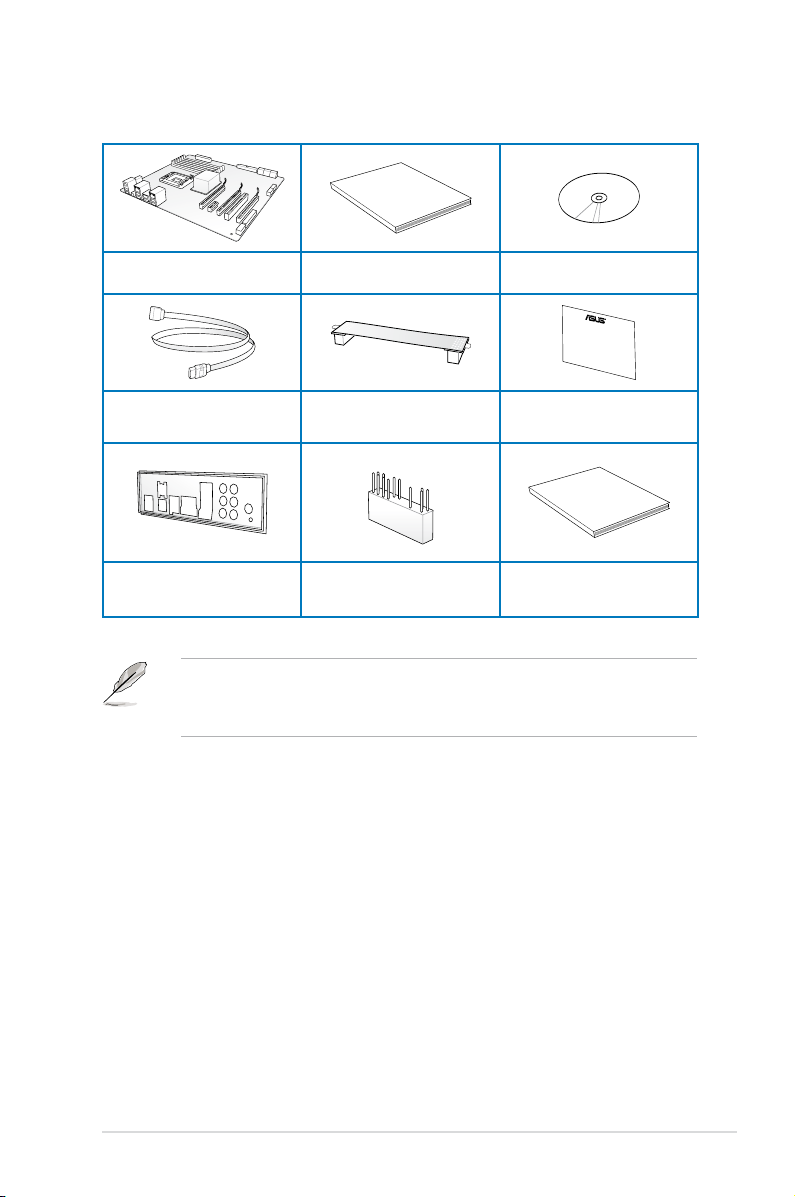
Package contents
User Manual
Five-year warranty
Check your motherboard package for the following items.
ASUS SABERTOOTH 990FX/GEN3
R2.0 motherboard
4 x Serial ATA 6.0 Gb/s cables 1 x ASUS SLI™ bridge connector 1 x TUF Certication card
1 x ASUS Q-Shield 1 x 2-in-1 ASUS Q-Connector kit 1 x TUF Five-year warranty manual
• If any of the above items is damaged or missing, contact your retailer.
• The illustrated items above are for reference only. Actual product specications may
vary with different models.
User manual Support DVD
xiii
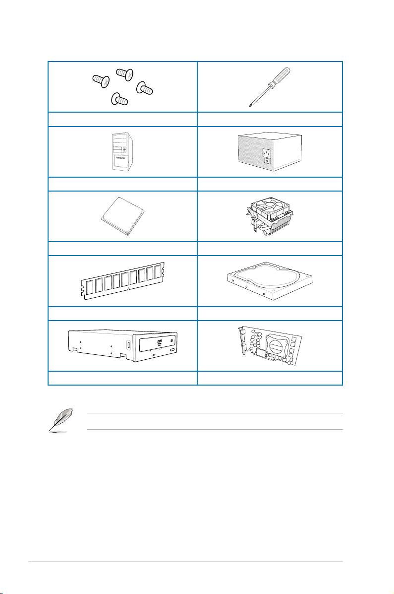
Installation tools and components
1 bag of screws Philips (cross) screwdriver
PC chassis Power supply unit
AMD AM3+ CPU AMD AM3+ compatible CPU Fan
DDR3 DIMM SATA hard disk drive
xiv
SATA optical disc drive (optional) Graphics card (optional)
The tools and components in the table above are not included in the motherboard package.

Chapter 1: Product Introduction
Product introduction
1
1.1 Special features
1.1.1 Product highlights
The Ultimate Force
The TUF series delivers a tough image with its unique design, and high-quality and militarystandard components. The TUF series pursues pre-eminent stability, all-around compatibility,
and extreme durability.
FX™/Phenom™ II/Athlon™ II/ Sempron™ 100 Series Processors (AM3+ / AM3
CPU)
This motherboard supports AMD® Socket AM3+ multi-core processors with up to 8-core
native CPU cores, and AMD® CPUs in the new 32nm manufacturing process. It provides
better overclocking capabilities with less power consumption. It features AMD Turbo CORE
Technology 2.0 to accelerate data transfer rate up to 5200MT/s rate via HyperTransport™ 3.0
based system bus.
AMD® 990FX Chipset
AMD 990FX Chipset is designed to support up to 5.2GT/s HyperTransport™ 3.0 (HT 3.0)
interface speed and dual PCI Express™ 2.0 x16 graphics. It is optimized with AMD AM3+
and multi-core CPUs to provide excellent system performance and overclocking capabilities.
PCI Express® 3.0
PCI Express® 3.0 (PCIe 3.0) is the latest PCI Express bus standard with improved encoding
schemes that provide twice the performance of current PCIe 2.0. Total bandwidth for a x16
link reaches a maximum of 32GB/s, double the 16GB/s of PCIe 2.0 (in x16 mode). As such,
PCIe 3.0 provides users unprecedented data speeds, combined with the convenience and
seamless transition offered by complete backward compatibility with PCIe 1.0 and PCIe
2.0 devices. PCIe 3.0 will become a must-have feature for users who wish to improve and
optimize graphic performance, as well as have the latest technology available to them.
QUAD-GPU SLI and QUAD-GPU CrossFireX™ Support
This motherboard supports multi-GPU congurations of both SLI™ and CrossFireX. This
motherboard features the AMD® 990FX/SB950 platform, optimizing PCIe allocation in multiple
GPU setups.
Dual-Channel 1866 MHz Support
The motherboard supports the dual-channel DDR3 memory that features data transfer
rates of 1866 MHz to boost the system’s performance, and to meet the higher bandwidth
requirements of 3D graphics, multimedia, and Internet applications.
Chapter 1
ASUS SABERTOOTH 990FX/GEN3 R2.0
1-1

Complete USB 3.0 Solution
This motherboard offers you the strategic USB 3.0 accessibility for both the front and rear
panels, allowing you to experience the convenience of the latest plug and play connectivity
solution at speed up to ten times faster than USB 2.0.
1.1.2 “Ultimate COOL!” Thermal Solution“Ultimate COOL!” Thermal Solution
TUF CeraM!X - Heatsink Coating Technology
This feature offers better cooling solution for an overall improvement in system stability. Its
innovative ceramics actively conducts heat away from the system, and replaces traditional
anti-oxidant for better heat dissipation.
TUF Thermal Radar
The TUF Thermal Radar monitors the temperature of the motherboard’s critical parts and
automatically adjusts fan speeds in real time to ensure that the system remains stable and
does not overheat. It consists of multiple sensors for various components, allowing you to
monitor each area, while increasing options for fan control housed inside the chassis. The
Thermal Radar calculates ideal fan speeds based on different parameters that you have
selected for each component, keeping your system cool and more stable.
1.1.3 “TUF ENGINE!” Power Design
DIGI+ Power Control
DIGI+ Power Control includes multiple digital voltage controllers, allowing ultra-precise
modulation and tuning of both CPU and DRAM. This innovative and industry-leading ASUS
technology provides accurate voltage tuning for better efciency, stability, and performance.
Efcient Switching Power (E.S.P.) Design
E.S.P., an ASUS exclusive feature, is designed for key components such as CPU, memory,
graphics cards, LAN, and USB 3.0 to help improve system efciency and reduce heat
generation.
TUF Components (Choke, Cap. & MOSFET; certied by military-standard)
This motherboard provides rugged performance even in the most challenging conditions
with its robust TUF chokes, solid capacitors, and MOSFETs, which are certied through a
Chapter 1
third-party, military-grade testing. TUF Chokes or Alloy Choke is made up of a compound
of various metals instead of the standard iron, which supports up to 40A rated current,
25% higher than the standard chokes. The TUF Chokes are packaged in a single piece,
eliminating the emission of vibration noise, delivering superb characteristics, and durability
under extreme conditions.
DO NOT uninstall the heatsink module by yourself. Doing so may bend the tubing and
affect the heat dissipation performance.
1-2
Chapter 1: Product introduction

1.1.4 “Safe & Stable!” Guardian Angel
ESD Guards
ESD (Electrostatic Discharge) Guards provides protection against electrostatic discharges,
which can damage the motherboard’s components. The ASUS exclusive Anti-Static chip
and circuit design, and the I/O shield provide four times better protection and ensure the
motherboard’s lifespan.
MemOK!
MemOK!, the remarkable memory rescue tool, allows you to simply press a button to
patch memory issues, ensure memory boot compatibility, determine fail-safe settings, and
dramatically improve the system’s bootup.
1.1.5 ASUS EZ DIY
ASUS UEFI BIOS (EZ Mode)
ASUS UEFI BIOS, a UEFI compliant architecture, offers the rst mouse-controlled intuitive
graphical BIOS interface that goes beyond the traditional keyboard-only BIOS controls,
providing you with more exibility, convenience, and easy to navigate EFI BIOS than the
traditional BIOS versions. It offers you with dual selectable modes and native support for hard
drives larger than 2.2 TB.
ASUS UEFI BIOS includes the following new features:
• F12 BIOS snapshot hotkey
• F3 Shortcut for most accessed information
• ASUS DRAM SPD (Serial Presence Detect) information detecting faulty DIMMs, and
helping with difcult POST situations.
DirectKey
DirectKey allows you to conveniently go into the BIOS setup with the press of a button. With
this feature, you can enter the BIOS anytime without having to press the <Del> key during
POST. It also allows you to shut down or turn on your computer and directly enter the BIOS
during boot-up.
Remote GO!
Remote GO! links PCs, tablets, smartphones, and TVs wirelessly together through an
existing LAN cable and route setup. It provides a seamless environment for a futuristic
connected lifestyle with three useful functions:
DLNA Media Hub: Enjoy HD video, music and photos stored in your PC, streaming to
•
your DLNA devices via Wi-Fi. You can even use your tablet to control your PC to play
multimedia contents.
Remote Desktop: Operate and control your PC in real time from a smartphone or tablet
•
for complete comfort and convenience.
File Transfer: Send and share les between your PC and smart devices* with only a
•
right click on the mouse.
* iPad/iPhone can send les, but cannot receive le transfers from PC.
Chapter 1
ASUS SABERTOOTH 990FX/GEN3 R2.0
1-3

USB BIOS Flashback
USB BIOS Flashback offers a hassle-free updating solution for your ultimate convenience.
Install a USB storage device containing the BIOS le, press the BIOS Flashback button for
about three seconds, and the UEFI BIOS is automatically updated even without entering
the existing BIOS or operating system. It also allows you to regularly check for UEFI BIOS
updates, and download the latest BIOS automatically.
USB 3.0 Boost
ASUS USB 3.0 Boost technology, which supports UASP (USB Attached SCSI Protocol),
automatically accelerates the data transfer speed of a USB 3.0 device up to 170% faster than
the standard USB 3.0 transfer speed.
Network iControl
Network iControl is an intuitive one-step network control center that makes it easier for you to
manage your bandwidth and allows you to set, monitor, and schedule the bandwidth priorities
for your network programs. It allows you to automatically connect to a PPPoE network for a
more convenient online experience.
ASUS EZ-Flash 2
ASUS EZ Flash 2 is a user-friendly utility that allows you to update the BIOS without using a
bootable oppy disk or an OS-based utility.
O.C. Prole
This motherboard features the ASUS O.C. Prole that allows you to store or load multiple
BIOS settings. The BIOS settings can be stored in the CMOS or a separate le, giving you
the freedom to share and distribute your favorite overclocking settings.
1.1.6 Other special features
8 Channel Audio Codec
The onboard 8-channel HD audio (High Denition Audio, previously codenamed Azalia)
CODEC enables high-quality Absolute Pitch 192kHz/24bit audio output, true BD lossless
sound, jack-sensing feature, retasking functions and multi-streaming technology.
S/PDIF-out on Back I/O port
This motherboard provides a convenient connectivity to external home theater audio systems
via optical S/PDIF-out (Sony-Philips Digital Interface) jacks. It allows the system to transfer
digital audio without converting to analog format and keeps the best signal quality.
ErP Ready
Chapter 1
The motherboard is European Union’s Energy-related Products (ErP) ready, and ErP requires
products to meet certain energy efciency requirement in regards to energy consumptions.
This is in line with ASUS vision of creating environment-friendly and energy-efcient products
through product design and innovation to reduce carbon footprint of the product and thus
mitigate environmental impacts.
1-4
Chapter 1: Product introduction

1.2 Motherboard overview
1.2.1 Before you proceed
Take note of the following precautions before you install motherboard components or change
any motherboard settings.
• Unplug the power cord from the wall socket before touching any component.
• Before handling components, use a grounded wrist strap or touch a safely groundedBefore handling components, use a grounded wrist strap or touch a safely grounded
object or a metal object, such as the power supply case, to avoid damaging them due
to static electricity.
• Hold components by the edges to avoid touching the ICs on them.Hold components by the edges to avoid touching the ICs on them.
• Whenever you uninstall any component, place it on a grounded antistatic pad or in the
bag that came with the component.
• Before you install or remove any component, ensure that the ATX power supply is
switched off or the power cord is detached from the power supply. Failure to do so
may cause severe damage to the motherboard, peripherals, or components.
ASUS SABERTOOTH 990FX/GEN3 R2.0
Chapter 1
1-5
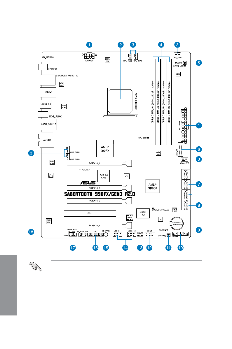
1.2.2 Motherboard layout
Chapter 1
1-6
Refer to 1.2.9 Internal connectors and 2.3.1 Rear I/O connection for more information
about rear panel connectors and internal connectors.
Chapter 1: Product introduction

Layout contents
Connectors/Jumpers/Slots Page
1. ATX power connectors (24-pin EATXPWR, 8-pin EATX12V) 1-36
2. AM3+ CPU socket 1-8
3. CPU, chassis, and optional fan connectors (4-pin CPU_FAN,
4-pin CPU_OPT, 4-pin CHA_FAN1-4 )
4. DDR3 DIMM slots 1-9
5. MemOK! button 1-25
6. USB 3.0 connector (20-1 pin USB3_56) 1-30
7. AMD® Serial ATA 6.0 Gb/s connectors (7-pin SATA6G_1-6 [brown]) 1-29
8. ASmedia® Serial ATA 6.0 Gb/s connectors
(7-pin SATA6G_E12 [gray])
9. Direct connector (2-pin DRCT) 1-38
10. System panel connector (20-8 pin PANEL) 1-37
11. DirectKey button 1-26
12. Serial port connector (10-1 pin COM1) 1-33
13. Clear RTC RAM (3-pin CLRTC) 1-27
14. USB 2.0 connectors (10-1 pin USB1314, USB1112) 1-32
15. Standby power LED 1-28
16. TPM connector (20-1 pin TPM) 1-38
17. Front panel audio connector (10-1 pin AAFP) 1-35
18. Digital audio connector (4-1 pin SPDIF_OUT) 1-31
1-34
1-30
ASUS SABERTOOTH 990FX/GEN3 R2.0
Chapter 1
1-7
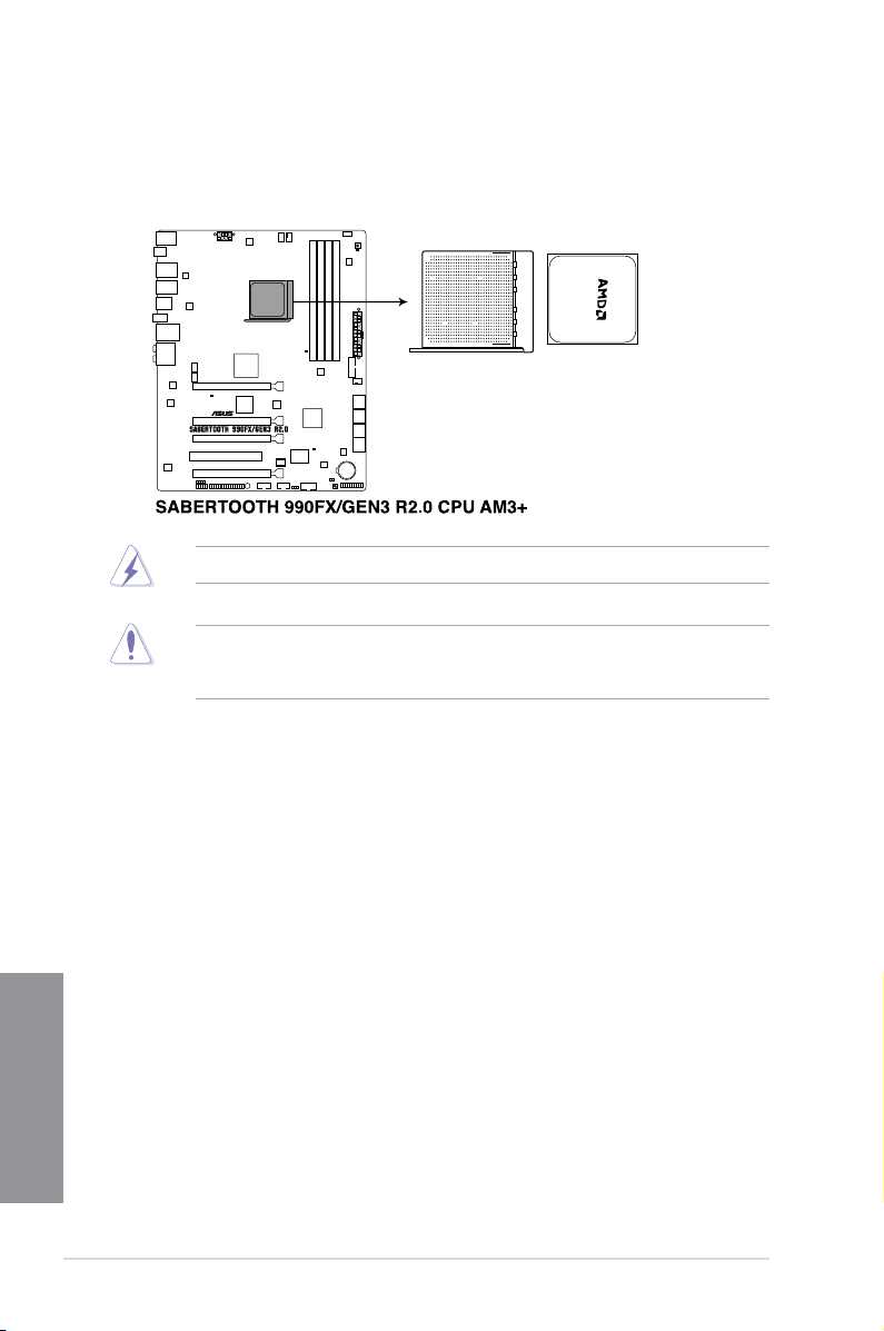
1.2.3 Central Processing Unit (CPU)
The motherboard comes with an AM3+ socket designed for AMD® FX Series CPU up to 8core, also compatible with AMD® socket AM3 for AMD® Phenom™ II/Athlon™ II/ Sempron™
100 Series Processors.
Ensure that all power cables are unplugged before installing the CPU.
The AM3+ socket has a different pinout design. Ensure that you use a CPU designed for
the AM3+/AM3 socket. The CPU ts in only one correct orientation. DO NOT force the CPU
into the socket to prevent bending the connectors on the socket and damaging the CPU!
Chapter 1
1-8
Chapter 1: Product introduction

1.2.4 System memory
The motherboard comes with four Double Data Rate 3 (DDR3) Dual Inline Memory Modules
(DIMM) slots.
A DDR3 module is notched differently from a DDR or DDR2 module. DO NOT install a DDR
or DDR2 memory module to the DDR3 slot.
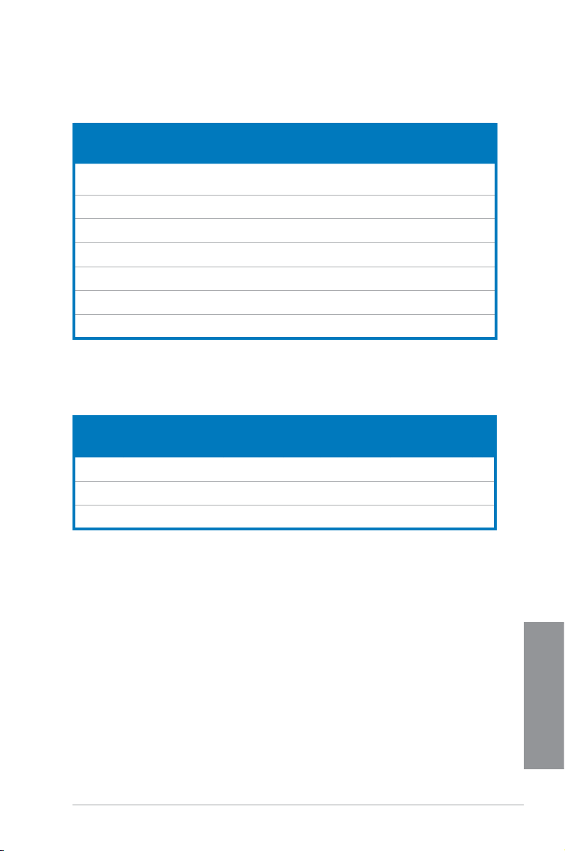
Recommended memory congurations
ASUS SABERTOOTH 990FX/GEN3 R2.0
Chapter 1
1-9

Memory congurations
You may install 1GB, 2GB, 4GB, 8GB, and 16GB ECC, non-ECC and unbuffered DDR3
DIMMs into the DIMM sockets.
• Memory module with memory frequency higher than 2133 MHz and its corresponding
timing or the loaded DRAM OC Prole is not the JEDEC memory standard. The
stability and compatibility of these memory modules depend on the CPU’s capabilities
and other installed devices.
• You may install varying memory sizes in Channel A and Channel B. The system maps
the total size of the lower-sized channel for the dual-channel conguration. Any excess
memory from the higher-sized channel is then mapped for single-channel operation.
• Due to CPU behavior, DDR3 1800 MHz memory module will run at the default
frequency of DDR3 1600 MHz.
• Always install DIMMs with the same CAS latency. For optimal compatibility, weAlways install DIMMs with the same CAS latency. For optimal compatibility, we
recommend that you install memory modules of the same version or date code (D/C)
from the same vendor. Check with the retailer to get the correct memory modules.
• Due to the memory address limitation on 32-bit Windows OS, when you install 4GBDue to the memory address limitation on 32-bit Windows OS, when you install 4GB
or more memory on the motherboard, the actual usable memory for the OS can be
about 3GB or less. For effective use of memory, we recommend that you do any of the
following:
a) Use a maximum of 3GB system memory if you are using a 32-bit Windows OS.Use a maximum of 3GB system memory if you are using a 32-bit Windows OS.
b) Install a 64-bit Windows OS when you want to install 4GB or more on theInstall a 64-bit Windows OS when you want to install 4GB or more on thenstall a 64-bit Windows OS when you want to install 4GB or more on the
motherboard.
c) For more details, refer to the Microsoft® support site at http://support.microsoft.
com/kb/929605/en-us.
• This motherboard does not support DIMMs made up of 512Mb (64MB) chips or less
(Memory chip capacity counts in Megabit, 8 Megabit/Mb = 1 Megabyte/MB).
Chapter 1
1-10
• The default memory operation frequency is dependent on its Serial Presence DetectThe default memory operation frequency is dependent on its Serial Presence Detect
(SPD), which is the standard way of accessing information from a memory module.
Under the default state, some memory modules for overclocking may operate at a
lower frequency than the vendor-marked value. To operate at the vendor-marked
or at a higher frequency, refer to section 3.4 Ai Tweaker menu for manual memory
frequency adjustment.
• For system stability, use a more efcient memory cooling system to support a fullFor system stability, use a more efcient memory cooling system to support a full
memory load (4 DIMMs) or overclocking condition.
Chapter 1: Product introduction
SABERTOOTH 990FX/GEN3 R2.0 Motherboard Qualied Vendors Lists (QVL)
DDR3 2400 MHz capability
Vendors Part No. Size SS/DSChip
CORSAIR CMZ16GX3M4A2400C9R
G.SKILL F3-19200CL10Q-
G.SKILL F3-19200CL11Q-
G.SKILL F3-19200CL9Q-
KINGSTON KHX24C11K4/16X(XMP) 16GB
Patriot PXD38G2400C11K(XMP) 8GB
Team TXD34096M2400HC9N-
(Ver4.13)(XMP)
32GBZHD(XMP)
16GBZHD(XMP)
16GBZMD (XMP)
L (XMP)
16GB
(4x4GB)
32GB
(4x8GB)
16GB
(4x4GB)
16GB
(4x4GB)
(4x4GB)
(2x4GB)
4GB DS SAMSUNG K4B2G0846D 9-9-9-24 1.65 • •
Brand
DS - - 2400
DS - - 10-12-
DS - - 11-11-
DS - - 9-11-
DS - - 11-13-
DS - - 11-11-
DDR3 2200 MHz capability
Vendors Part No. Size SS/DSChip
G.SKILL F3-17600CL7D-4GBFLS(XMP) 4G
GEIL GET34GB2200C9DC(XMP) 4GB
KINGMAX FLKE85F-B8KJAA-FEIS(XMP) 4GB
DS - - 7-10-10-28 1.65 • • •
(2x2G)
DS - - 9-10-9-28 1.65 • • •
(2x2GB)
DS Kingmax N/A - - • •
(2x2GB)
Chip NO. Timing Voltage DIMM socket
1.65 • •
9-1111-31
1.65 • •
12-31
1.65 • •
11-31
1.65 • •
11-31
1.65 • •
13-30
1.65 • •
11-30
Chip
Brand
Timing Voltage DIMM socket
NO.
support (Optional)
1 2 4
support (Optional)
1 2 4
ASUS SABERTOOTH 990FX/GEN3 R2.0
Chapter 1
1-11

DDR3 2133 MHz capability
Vendors Part No. Size SS/DSChip Brand Chip
CORSAIR CMD8GX3M2A2133C9
CORSAIR CMT4GX3M2B2133C9
CORSAIR CMT4GX3M2B2133C9
G.SKILL F3-17000CL11Q2-
G.SKILL F3-17000CL9Q-16GBZH
G.SKILL F3-17066CL9Q-
KINGSTON KHX2133C11D3K4/
KINGSTON KHX2133C11D3T1K2/
KINGSTON KHX21C11T1BK2/8X
Patriot PVV34G2133C9K (XMP) 4GB
Patriot PXD38G2133C11K (XMP) 8GB
Team TXD34096M2133HC9N-
(Ver1.5)(XMP)
(Ver7.1)(XMP)
(XMP)
64GBZLD (XMP)
(XMP)
16GBTDD(XMP)
16GX(XMP)
16GX (XMP)
(XMP)
L(XMP)
8GB
DS - - 9-11-
(2x4GB)
4GB
DS - - 9-9-9-241.5 • • •
(2x2GB)
4GB
DS - - 9-10-
(2x2GB)
64GB
DS - - 11-11-
(8x8GB)
16GB
DS - - 9-11-
(4x4GB)
16GB
DS - - 9-9-9-241.65 • •
(4x4GB)
16GB
DS - - 11-12-
(4x4GB)
16GB
DS - - 9-9-9-
(2x8GB)
8GB
DS - - 11-12-
(2x4GB)
DS - - 9-11-
(2x2GB)
DS - - 9-9-9-
(2x4GB)
4GB DS SAMSUNG K4B2G
NO.
0846D
Timing Voltage DIMM socket
10-27
9-27
11-30
10-28
11-30
24
11-30
9-27
24
9-9-924
support (Optional)
1 2 4
1.5 • •
1.5 • •
1.5 • • •
1.65 • • •
1.65 • • •
1.6 • •
1.6 • • •
1.66 • • •
1.65 • • •
1.65 • • •
Chapter 1
1-12
Chapter 1: Product introduction

DDR3 2000 MHz capability
Vendors Part No. Size SS/DSChip
AEXEA AXA3ES2G2000LG28V
(XMP)
AEXEA AXA3ES4GK2000LG28V
(XMP)
Apacer 78.AAGD5.9KD (XMP) 6GB
Asint SLA302G08-ML2HB
(XMP)
G.SKILL F3-16000CL9D-4GBRH
(XMP)
G.SKILL F3-16000CL9D-4GBTD
(XMP)
GEIL GUP34GB2000C9DC
(XMP)
Patriot PV736G2000ELK
(XMP)
Patriot PVT36G2000LLK
(XMP)
Patriot PX7312G2000ELK
(XMP)
Silicon
SP002GBLYU200S02
Power
(XMP)
Team TXD32048M2000C9
(XMP)
Team TXD32048M2000C9-L
(XMP)
Team TXD32048M2000C9-L
(XMP)
2GB DS - - - 1.65 • • •
4GB
(2x2GB)
(3x2GB)
4GB DS Hynix H5TQ2G83BFRH9C 9-9-9-27 - • • •
4GB
(2x2GB)
4GB
(2x2GB)
4GB
(2x2GB)
6GB
(3x2GB)
6GB
(3x2GB)
12GB
(3x4GB)
2GB DS - - - - • • •
2GB DS Team T3D1288RT-20 9-9-9-24 1.5 • • •
2GB DS Team T3D1288LT-20 9-9-9-24 1.5 • • •
2GB DS Team T3D1288RT-20 9-9-9-24 1.6 • •
Brand
DS - - - 1.65 • • •
DS - - 9-9-9-27 - • •
DS - - 9-9-9-24 1.65 • •
DS - - 9-9-9-24 1.65 • •
DS - - 9-9-9-28 1.65 • • •
DS - - 7-7-7-20 1.65 • • •
DS - - 8-8-8-24 1.65 • •
DS - - 9-11-9-27 1.65 • •
Chip NO. Timing Voltage DIMM socket
support
(Optional)
1 2 4
ASUS SABERTOOTH 990FX/GEN3 R2.0
Chapter 1
1-13

DDR3 1866 MHz capability
Vendors Part No. Size SS/DSChip
CORSAIR CMD16GX3M4A1866C9
CORSAIR CMD16GX3M4A1866C9
CORSAIR CMD8GX3M2A1866C9
CORSAIR CMD8GX3M2A1866C9
CORSAIR CMT32GX3M4X1866C9
CORSAIR CMZ16GX3M4X1866C9R
CORSAIR CMZ16GX3M4X1866C9R
CORSAIR CMZ32GX3M4X1866C10
CORSAIR CMZ32GX3M4X1866C10
CORSAIR CMZ8GX3M2A1866C9
CORSAIR CMZ8GX3M2A1866C9
CORSAIR CMZ8GX3M2A1866C9G
Crucial BLE4G3D1869DE1XT0.1
G.SKILL F3-14900CL10Q2-
G.SKILL F3-14900CL9D-
G.SKILL F3-14900CL9Q-16GBXL
G.SKILL F3-14900CL9Q-16GBZL
G.SKILL F3-14900CL9Q-8GBFLD
KINGSTON KHX1866C9D3K2/8GX
Chapter 1
Patriot PXD34G1866ELK (XMP) 4GB
Patriot PXD38G1866ELK (XMP) 8GB
Patriot PXD38G1866ELK (XMP) 8GB
Patriot PXD38G1866ELK (XMP) 8GB
Team TXD34096M1866HC9K-
(Ver4.13)(XMP)
(Ver8.16)(XMP)
(Ver4.13)(XMP)
(Ver8.16)(XMP)
(Ver3.23)(XMP)
(Ver8.16)(XMP)
(Ver8.16)(XMP)
(Ver3.23)(XMP)
(Ver3.23)(XMP)
(Ver8.16)(XMP)
(XMP)
(Ver5.12)(XMP)
6FMD(XMP)
64GBZLD (XMP)
8GBSR(XMP)
(XMP)
(XMP)
(XMP)
(XMP)
L (XMP)
Chip NO. Timing Voltage DIMM socket
Brand
16GB
DS - - 9-10-9-27 1.5 • • •
(4x4GB)
16GB
DS - - 9-10-9-27 1.5 • •
(4x4GB)
8GB
DS - - - 1.5 • • •
(2x4GB)
8GB
DS - - 9-10-9-27 1.5 • • •
(2x4GB)
32GB
DS - - 9-10-9-27 1.5 • • •
(4x8GB)
16GB
DS - - 9-10-9-27 1.5 • • •
(4x4GB)
16GB
DS - - 9-10-9-27 1.5 • • •
(4x4GB)
32GB
DS - - 10-11-10-27 1.5 • • •
(4x8GB)
32GB
DS - - 10-11-10-27 1.5 • •
(4x8GB)
8GB
DS - - 9-10-9-27 1.5 • • •
(2x4GB)
8GB
DS - - 9-10-9-27 1.5 • • •
(2x4GB)
8GB
DS - - 1866 9-10-
(2x4GB)
4GB DS - - 9-9-9-27 1.5 • • •
64GB
DS - - 10-11-10-30 1.5 • • •
(8x8GB)
8GB
DS - - 9-10-9-28 1.5 • • •
( 2x
4GB)
16GB
DS - - 9-10-9-28 1.5 • • •
(4x4GB)
16GB
DS - - 9-10-9-28 1.5 • • •
(4x4GB)
8GB
DS - - 9-9-9-24 1.6 • • •
(2x4GB)
8GB
DS - - - 1.65 •
(2x4GB)
SS - - 9-9-9-24 1.65 • • •
(2x2GB)
DS - - 9-11-9-27 1.65 • • •
(2x4GB)
DS - - 9-11-9-27 1.65 • • •
(2x4GB)
DS - - 1866 9-10(2x4GB)
4GB DS Hynix H5TC2G83BFRH9A 9-11-9-27 1.65 • • •
9-27
9-27
support
(Optional)
1 2 4
1.5 • • •
1.5 • • •
1-14
Chapter 1: Product introduction

DDR3 1800 MHz capability
Vendors Part No. Size SS/DSChip
G.SKILL F3-14400CL9D-
4GBRL(XMP)
4GB
DS - - 9-9-9-24 1.6 • • •
(2x2GB)
Brand
Chip
Timing Voltage DIMM socket support
NO.
(Optional)
1 2 4
DDR3 1600 MHz capability
Vendors Part No. Size SS/DSChip
AMD AE32G1609U1-U 2GB SS AMD 23EY4587MB6H - 1.5 • • •
AMD AP38G1608U2K
(XMP)
Apacer 78.B1GE3.9L10C 4GB DS Apacer AM5D5908DEQSCK - 1.65 • • •
Apacer AHU04GFA60C9Q1D
(XMP)
Asint SLA302G08-EGG1C
(XMP)
Asint SLA302G08-EGJ1C
(XMP)
Asint SLA302G08-EGN1C 4GB DS ASint 302G08-GN1C - - • • •
Asint SLB304G08-EGN1B 8GB DS ASint 304G08-GN1B - - • • •
Asint SLZ302G08-EGN1C 2GB SS ASint 302G08-GN1C - - • • •
Asint SLZ3128M8-EGJ1D
(XMP)
ATP AQ12M64B8BKK0S 4GB DS SAMSUNG K4B2G08460 - NO • • •
8GB
(2x4GB)
4GB DS - - 9-9-9-27 1.65 • • •
4GB DS Asint 302G08-GG1C 9-9-9-27 - • • •
4GB DS Asint 302G08-GJ1C 9-9-9-27 - • • •
2GB DS Asint 3128M8-GJ1D - - • • •
Brand
DS - - 9-9-9-28 1.65 • •
(continued on the next page)
Chip NO. Timing Voltage DIMM socket
support
(Optional)
1 2 4
ASUS SABERTOOTH 990FX/GEN3 R2.0
Chapter 1
1-15

DDR3 1600 MHz capability
Vendors Part No. Size SS/DSChip
CENTURY CD4G-D3U1600 4GB DS ELPIDA EDJ2108BDBG-
CENTURY CD4G-D3U1600 4GB DS Hynix H5TQ2G83CFR-
CENTURY CD8G-D3U1600 8GB DS ELPIDA EDJ4208BBBG-
CENTURY CD8G-D3U1600 8GB DS Hynix H5TQ4G83MFR-
CORSAIR CMD16GX3M2A1600C9
CORSAIR CMD8GX3M2A1600C8
CORSAIR CMD8GX3M2A1600C9
CORSAIR CMG4GX3M2A1600C6 4GB
CORSAIR CML16GX3M4X1600C8
CORSAIR CMP6GX3M3A1600C8
CORSAIR CMP6GX3M3A1600C8
CORSAIR CMX6GX3M3C1600C7
CORSAIR CMX8GX3M2A1600C9
CORSAIR CMZ16GX3M2A1600C10
CORSAIR CMZ16GX3M4A1600C9
CORSAIR CMZ32GX3M4X1600C10
CORSAIR CMZ8GX3M2A1600C8
CORSAIR CMZ8GX3M2A1600C9
CORSAIR CMZ8GX3M4X1600C9
Chapter 1
CORSAIR HX3X12G1600C9 (XMP) 12GB
(Ver8.21)(XMP)
(Ver5.12)(XMP)
(Ver2.12)(XMP)
(Ver 2.12)(XMP)
(XMP)
(XMP)
(XMP)
(Ver3.19)(XMP)
(Ver.3.24)(XMP)
(XMP)
(Ver2.2)(XMP)
(XMP)
(XMP)
(Ver 2.12)(XMP)
Chip NO. Timing Voltage DIMM
Brand
GN-F
PBC
GN-F
PBC
16GB
DS - - 9-9-9-24 1.5 • •
(2x8GB)
8GB
DS - - 1600 8-8-
(2x4GB)
8GB
DS - - 9-9-9-24 1.5 • • •
(2x4GB)
DS - - 6-6-6-18 1.65 • • •
(2x2GB)
16GB
DS - - Heat-Sink
(4x4GB)
6GB
DS - - 8-8-8-24 1.65 • • •
(3x2GB)
6GB
DS - - 8-8-8-24 1.65 • • •
(3x2GB)
6GB
DS - - 7-8-7-20 1.65 • • •
( 3x
2GB)
8GB
SS - - 9-9-9-24 1.65 • • •
(2x4GB)
16GB
DS - - 10-10-10-27 1.5 • • •
(2x8GB)
16GB
DS - - 9-9-9-24 1.5 • • •
(4x4GB)
32GB
DS - - 10-10-10-27 1.5 • • •
(4x8GB)
8GB
DS - - 8-8-8-24 1.5 • • •
(2x4GB)
8GB
DS - - 9-9-9-24 1.5 • • •
(2x4GB)
8GB
SS - - 9-9-9-24 1.5 • • •
(4x2GB)
DS - - 9-9-9-24 1.6 • • •
(6x2GB)
- 1.5 • • •
- 1.5 • • •
- 1.5 • • •
- 1.5 • • •
8-24
Package
(continued on the next page)
socket
support
(Optional)
1 2 4
1.5 • • •
1.5 • • •
1-16
Chapter 1: Product introduction
 Loading...