


Z87-WS
Motherboard

E8226
First Edition
May 2013
Copyright© 2013 ASUSTeK COMPUTER INC. All Rights Reserved.
No part of this manual, including the products and software described in it, may be reproduced,
transmitted, transcribed, stored in a retrieval system, or translated into any language in any form or by any
means, except documentation kept by the purchaser for backup purposes, without the express written
permission of ASUSTeK COMPUTER INC. (“ASUS”).
Product warranty or service will not be extended if: (1) the product is repaired, modied or altered, unless
such repair, modication of alteration is authorized in writing by ASUS; or (2) the serial number of the
product is defaced or missing.
ASUS PROVIDES THIS MANUAL “AS IS” WITHOUT WARRANTY OF ANY KIND, EITHER EXPRESS
OR IMPLIED, INCLUDING BUT NOT LIMITED TO THE IMPLIED WARRANTIES OR CONDITIONS OF
MERCHANTABILITY OR FITNESS FOR A PARTICULAR PURPOSE. IN NO EVENT SHALL ASUS, ITS
DIRECTORS, OFFICERS, EMPLOYEES OR AGENTS BE LIABLE FOR ANY INDIRECT, SPECIAL,
INCIDENTAL, OR CONSEQUENTIAL DAMAGES (INCLUDING DAMAGES FOR LOSS OF PROFITS,
LOSS OF BUSINESS, LOSS OF USE OR DATA, INTERRUPTION OF BUSINESS AND THE LIKE),
EVEN IF ASUS HAS BEEN ADVISED OF THE POSSIBILITY OF SUCH DAMAGES ARISING FROM ANY
DEFECT OR ERROR IN THIS MANUAL OR PRODUCT.
SPECIFICATIONS AND INFORMATION CONTAINED IN THIS MANUAL ARE FURNISHED FOR
INFORMATIONAL USE ONLY, AND ARE SUBJECT TO CHANGE AT ANY TIME WITHOUT NOTICE,
AND SHOULD NOT BE CONSTRUED AS A COMMITMENT BY ASUS. ASUS ASSUMES NO
RESPONSIBILITY OR LIABILITY FOR ANY ERRORS OR INACCURACIES THAT MAY APPEAR IN THIS
MANUAL, INCLUDING THE PRODUCTS AND SOFTWARE DESCRIBED IN IT.
Products and corporate names appearing in this manual may or may not be registered trademarks or
copyrights of their respective companies, and are used only for identication or explanation and to the
owners’ benet, without intent to infringe.
Offer to Provide Source Code of Certain Software
This product contains copyrighted software that is licensed under the General Public License (“GPL”),
under the Lesser General Public License Version (“LGPL”) and/or other Free Open Source Software
Licenses. Such software in this product is distributed without any warranty to the extent permitted by the
applicable law. Copies of these licenses are included in this product.
Where the applicable license entitles you to the source code of such software and/or other additional data,
you may obtain it for a period of three years after our last shipment of the product, either
(1) for free by downloading it from http://support.asus.com/download
or
(2) for the cost of reproduction and shipment, which is dependent on the preferred carrier and the location
where you want to have it shipped to, by sending a request to:
ASUSTeK Computer Inc.
Legal Compliance Dept.
15 Li Te Rd.,
Beitou, Taipei 112
Taiwan
In your request please provide the name, model number and version, as stated in the About Box of the
product for which you wish to obtain the corresponding source code and your contact details so that we
can coordinate the terms and cost of shipment with you.
The source code will be distributed WITHOUT ANY WARRANTY and licensed under the same license as
the corresponding binary/object code.
This offer is valid to anyone in receipt of this information.
ASUSTeK is eager to duly provide complete source code as required under various Free Open Source
Software licenses. If however you encounter any problems in obtaining the full corresponding source
code we would be much obliged if you give us a notication to the email address gpl@asus.com, stating
the product and describing the problem (please DO NOT send large attachments such as source code
archives, etc. to this email address).
ii

Contents
Safety information ..................................................................................................... vii
About this guide ....................................................................................................... viii
Z87-WS specications summary ............................................................................... x
Package contents ...................................................................................................... xv
Installation tools and components ......................................................................... xvi
Chapter 1: Product Introduction
1.1 Special features..........................................................................................1-1
1.1.1 Product highlights
1.1.2 ASUS Workstation Exclusive Features .......................................
1.1.3 Dual Intelligent Processors 4 with 4-Way Optimization ...............
1.1.4 ASUS Exclusive Features ...........................................................
1.1.5 ASUS Quiet Thermal Solution .....................................................
1.1.6 ASUS EZ DIY ..............................................................................
1.1.7 Other special features .................................................................
1.2 Motherboard overview ...............................................................................
1.2.1 Before you proceed .....................................................................
1.2.2 Motherboard layout .....................................................................
1.2.3 Central Processing Unit (CPU) .................................................
1.2.4 System memory ........................................................................
1.2.5 Expansion slots .........................................................................
1.2.6 Onboard buttons and switches
1.2.7 Onboard LEDs ..........................................................................
1.2.8 Internal connectors
........................................................................ 1-1
.................................................. 1-17
.................................................................... 1-31
1-3
1-4
1-5
1-6
1-6
1-7
1-8
1-8
1-9
1-11
1-12
1-15
1-23
Chapter 2: Basic installation
2.1 Building your PC system...........................................................................2-1
2.1.1 Motherboard installation ..............................................................
2.1.2 CPU installation
2.1.3 CPU heatsink and fan assembly installation ...............................
2.1.4 DIMM installation
2.1.5 ATX Power connection ................................................................
2.1.6 SATA device connection ..............................................................
2.1.7 Front I/O Connectors
2.1.8 Expansion Card installation
........................................................................... 2-3
......................................................................... 2-6
................................................................... 2-9
....................................................... 2-10
2-1
2-4
2-7
2-8
iii

2.2 BIOS update utility ................................................................................... 2-11
2.3 Motherboard rear and audio connections .............................................
2.3.1 Rear I/O connection ..................................................................
2.3.2 Audio I/O connections ...............................................................
2.4 Starting up for the rst time ....................................................................
2.5 Turning off the computer .........................................................................
2-13
2-13
2-15
2-17
2-18
Chapter 3: BIOS setup
3.1 Knowing BIOS ............................................................................................3-1
3.2 BIOS setup program ..................................................................................
3.2.1 EZ Mode
3.2.2 Advanced Mode ..........................................................................
3.3 My Favorites ...............................................................................................
3.4 Main menu ..................................................................................................
3.5 Ai Tweaker menu ........................................................................................
3.6 Advanced menu .......................................................................................
3.6.1 CPU Conguration ....................................................................
3.6.2 PCH Conguration ....................................................................
3.6.3 SATA Conguration ...................................................................
3.6.4 System Agent Conguration
3.6.5 USB Conguration ....................................................................
3.6.6 Platform Misc Conguration ......................................................
3.6.7 Onboard Devices Conguration ................................................
3.6.8 APM ..........................................................................................
3.6.9 Network Stack ...........................................................................
3.7 Monitor menu ...........................................................................................
3.8 Boot menu ................................................................................................
3.9 Tools menu ...............................................................................................
3.9.1 ASUS EZ Flash 2 Utility ............................................................
3.9.2 ASUS O.C. Prole .....................................................................
3.9.3 ASUS SPD Information .............................................................
3.10 Exit menu ..................................................................................................
3.11 Updating BIOS ..........................................................................................
3.11.1 EZ Update .................................................................................
3.11.2 ASUS EZ Flash 2 ......................................................................
3.11.3 ASUS CrashFree BIOS 3 ..........................................................
3.11.4 ASUS BIOS Updater .................................................................
...................................................................................... 3-3
...................................................... 3-31
3-2
3-4
3-6
3-7
3-9
3-24
3-25
3-28
3-29
3-33
3-34
3-35
3-37
3-38
3-39
3-42
3-48
3-48
3-48
3-49
3-50
3-51
3-51
3-52
3-53
3-54
iv

Chapter 4: Software support
4.1 Installing an operating system .................................................................4-1
4.2 Support DVD information ..........................................................................
4.2.1 Running the support DVD ...........................................................
4.2.2 Obtaining the software manuals
.................................................. 4-2
4.3 Software information .................................................................................
4.3.1 AI Suite 3
..................................................................................... 4-3
4.3.2 Dual Intelligent Processors 4 ......................................................
4.3.3 EPU .............................................................................................
4.3.4 DIGI+ Power Control .................................................................
4.3.5 Fan Xpert 2 ...............................................................................
4.3.6 USB 3.0 Boost
4.3.7 Network iControl
........................................................................... 4-15
........................................................................ 4-16
4.3.8 USB BIOS Flashback ................................................................
4.3.9 Ai Charger+ ...............................................................................
4.3.10 EZ Update .................................................................................
4.3.11 USB Charger+ ...........................................................................
4.3.12 System Information ...................................................................
4.3.13 ASUS SSD Caching II ...............................................................
4.3.14 Audio congurations
.................................................................. 4-26
4.3.15 ASUS Dr. Power Utility ..............................................................
4-1
4-1
4-3
4-5
4-8
4-10
4-12
4-18
4-19
4-20
4-21
4-22
4-24
4-27
Chapter 5: RAID support
5.1 RAID congurations ..................................................................................5-1
5.1.1 RAID denitions ..........................................................................
5.1.2 Installing Serial ATA hard disks ...................................................
5.1.3 Setting the RAID item in BIOS ....................................................
5.1.4 Intel
5.2 Creating a RAID driver disk
®
Rapid Storage Technology Option ROM utility ..................5-3
....................................................................... 5-7
5.2.1 Creating a RAID driver disk without entering the OS ..................
5.2.2 Creating a RAID driver disk in Windows
5.2.3 Installing the RAID driver during Windows
®
.................................... 5-8
®
OS installation ........ 5-8
5-1
5-2
5-2
5-7
v

Chapter 6: Multiple GPU support
6.1 ATI® CrossFireX™ technology ..................................................................6-1
6.1.1 Requirements ..............................................................................
6.1.2 Before you begin .........................................................................
6.1.3 Installing two CrossFireX™ graphics cards ................................
6.1.4 Installing three CrossFireX™ graphics cards ..............................
6.1.5 Installing four CrossFireX™ graphics cards ................................
6.1.6 Installing the device drivers .........................................................
6.1.7 Enabling the AMD
6.2 NVIDIA
®
SLI™ technology ......................................................................... 6-7
®
CrossFireX™ technology ............................. 6-5
6.2.1 Requirements ..............................................................................
6.2.2 Installing two SLI-ready graphics cards ......................................
6.2.3 Installing three SLI-ready graphics cards ....................................
6.2.4 Installing four SLI-ready graphics cards ....................................
6.2.5 Enabling the NVIDIA® SLI™ technology ..................................
6.3 NVIDIA
®
CUDA™ technology .................................................................. 6-13
6.3.1 Requirements ............................................................................
6.3.2 Installing CUDA-ready graphics cards ......................................
6-1
6-1
6-2
6-3
6-4
6-5
6-7
6-8
6-9
6-10
6-11
6-13
6-13
Appendices
Notices .................................................................................................................... A-1
ASUS contact information ...................................................................................... A-5
vi

Safety information
Electrical safety
To prevent electrical shock hazard, disconnect the power cable from the electrical outlet
•
before relocating the system.
When adding or removing devices to or from the system, ensure that the power cables
•
for the devices are unplugged before the signal cables are connected. If possible,
disconnect all power cables from the existing system before you add a device.
Before connecting or removing signal cables from the motherboard, ensure that all
•
power cables are unplugged.
Seek professional assistance before using an adapter or extension cord. These devices
•
could interrupt the grounding circuit.
Ensure that your power supply is set to the correct voltage in your area. If you are not
•
sure about the voltage of the electrical outlet you are using, contact your local power
company.
If the power supply is broken, do not try to x it by yourself. Contact a qualied service
•
technician or your retailer.
Operation safety
Before installing the motherboard and adding devices on it, carefully read all the manuals
•
that came with the package.
Before using the product, ensure all cables are correctly connected and the power
•
cables are not damaged. If you detect any damage, contact your dealer immediately.
To avoid short circuits, keep paper clips, screws, and staples away from connectors,
•
slots, sockets and circuitry.
Avoid dust, humidity, and temperature extremes. Do not place the product in any area
•
where it may become wet.
Place the product on a stable surface.
•
If you encounter technical problems with the product, contact a qualied service
•
technician or your retailer.
vii

About this guide
This user guide contains the information you need when installing and conguring the
motherboard.
How this guide is organized
This guide contains the following parts:
• Chapter 1: Product introduction
This chapter describes the features of the motherboard and the new technology it
supports. It includes description of the switches, jumpers, and connectors on the
motherboard.
• Chapter 2: Basic installation
This chapter lists the hardware setup procedures that you have to perform when
installing system components.
• Chapter 3: BIOS setup
This chapter tells how to change system settings through the BIOS Setup menus.
Detailed descriptions of the BIOS parameters are also provided.
• Chapter 4: Software support
This chapter describes the contents of the support DVD that comes with the
motherboard package and the software.
• Chapter 5: RAID support
This chapter describes the RAID congurations.
Where to nd more information
Refer to the following sources for additional information and for product and software
updates.
1. ASUS websites
The ASUS website provides updated information on ASUS hardware and software
products. Refer to the ASUS contact information.
2. Optional documentation
Your product package may include optional documentation, such as warranty yers,
that may have been added by your dealer. These documents are not part of the
standard package.
viii

Conventions used in this guide
To ensure that you perform certain tasks properly, take note of the following symbols used
throughout this manual.
DANGER/WARNING: Information to prevent injury to yourself when trying to
complete a task.
CAUTION: Information to prevent damage to the components when trying to
complete a task
IMPORTANT: Instructions that you MUST follow to complete a task.
NOTE: Tips and additional information to help you complete a task.
Typography
Bold text Indicates a menu or an item to select.
Italics
<Key> Keys enclosed in the less-than and greater-than sign
<Key1> + <Key2> + <Key3> If you must press two or more keys simultaneously, the key
Used to emphasize a word or a phrase.
means that you must press the enclosed key.
Example: <Enter> means that you must press the Enter or
Return key.
names are linked with a plus sign (+).
ix

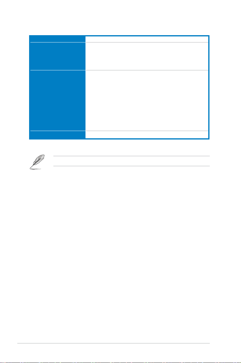
Z87-WS specications summary
CPU LGA1150 socket for the 4th Generation Intel® Core™ i7/Intel®
Core™i5/ Intel® Core™ i3, Pentium® and Celeron® processors
Supports 22nm CPU
Supports Intel® Turbo Boost Technology 2.0*
* The Intel® Turbo Boost Technology 2.0 support depends on the CPU
types.
Chipset Intel® Z87 Express Chipset
Memory 4 x DIMM, max. 32GB, DDR3 2800 (O.C.)* / 2666 (O.C.)* 2600
(O.C.)* / 2500 (O.C.)* / 2400 (O.C.)* / 2200(O.C.)* / 2133(O.C.)* /
2000 (O.C.)* / 1866(O.C.)* / 1800(O.C.)* /1600 / 1333 MHz, non-
ECC, un-buffered memory
Dual channel memory architecture
Supports Intel® Extreme Memory Prole (XMP)
* Hyper DIMM support is subject to the physical characteristics of
individual CPUs. Please refer to Memory QVL (Qualied Vendors List)
for details.
Expansion slots 4 x PCI Express 3.0*/2.0 x16 slots (single at x16, dual at x16/x16
mode, triple at x16/x8/x8, quad at x8/x8/x8/x8)
2 x PCI Express 2.0 x1 slots
VGA Integrated Graphics Processor - Intel® HD Graphics support
Multi-VGA output support: DisplayPort/Mini DisplayPort/HDMI port
Supports DisplayPort 1.2* with max. resolution 4096x2160@24Hz
and 3840x2160@60Hz
Supports HDMI with max. resolution of 4096x2160@24Hz and
2560x1600@60Hz
Supports Intel® InTru™ 3D, Intel® Quick Sync Video, Intel® Clear
Video HD Technology, and Intel® Insider™
Supports up to three displays simultaneously
Maximum shared memory 1024MB
* DisplayPort 1.2 Multi-Stream Transport compliant, supports
DisplayPort 1.2 monitor daisy chain up to 3 displays.
Multi-GPU support Supports NVIDIA® 4-Way SLI™ Technology
Supports AMD® 4-Way CrossFireX™ Technology
LAN 2 x Intel® I210 Gigabit LAN controller
(continued on the next page)
x

Z87-WS specications summary
Storage
Intel® Z87 Express Chipset with RAID 0, 1, 5, 10
- 6 x SATA 6.0 Gb/s ports (yellow)
- Supports Intel
Response Technology, Intel® Rapid Start Technology, Intel®
Smart Connect Technology*
®
Dynamic Storage Accelerator, Intel® Smart
Marvell® 9230 SATA controllers
- 4 x SATA 6Gb/s ports with RAID 0, 1, 10 and port multiplier
support
ASMedia® SATA 6Gb/s controller**
- 2 x eSATA 6Gb/s ports with port multiplier support
* Supported on Intel® Core™ processor family.
** These SATA ports are for data hard drives only. ATAPI devices are not
supported.
1394 VIA VT6315N controller support 1x1394a port
Audio
Realtek® ALC1150 8-channel high denition audio
CODEC
- High quality 112dB SNR stereo playback output (Line-out at
rear) and 104dB SNR recording input (Line-in) support.
- Absolute Pitch 192khz/24-bit True BD Lossless Sound
- BD audio layer content protection
- DTS UltraPC II
- DTS Connect
- Supports jack-detection, multi-streaming and front panel jackretasking
- Optical S/PDIF out ports at rear I/O
USB
Intel® Z87 Express Chipset - supports ASUS USB 3.0
Boost
- 1 x USB 3.0/2.0 ports at rear panel (blue)
- 2 x USB 3.0/2.0 ports at mid-board for front panel support
- 4 x USB 2.0/1.1 ports at rear panel
- 5 x USB 2.0/1.1 ports at mid-board
ASMedia® USB 3.0 controller - supports ASUS USB 3.0
Boost
- 3 x USB 3.0/2.0 ports at rear panel (blue)
Workstation unique
features
4 PCIe x 16 slots
ASUS Dr. Power
Quick gate: 1 vertical USB 2.0 on board
ASUS WS Diag. LED
(continued on the next page)
xi

Z87-WS specications summary
ASUS unique features
ASUS Dual Intelligent Processors 4 with 4-Way
Optimization
- 4-Way Optimization tuning key perfectly consolidates
ASUS-exclusive DIGI+Power Control, TPU, EPU, and Fan
Xpert 2 that quickly optimize the digital power setting, system
performance, power saving and whole system cooling
conguration with just a click.
CPU Power
- Industry leading digital 8-phase power design
- ASUS CPU power utility
DRAM Power
- Industry leading digital 2-phase DRAM power design
- ASUS DRAM power utility
ASUS EPU
- EPU, EPU switch
ASUS TPU
- TurboV, GPU Boost, TPU switch
ASUS Fan Xpert 2
- Featuring Fan Auto Tuning function for optimized speed
control.
ASUS Exclusive Features:
- Network iControl featuring instant network bandwidth
domination for top network program in use
- USB 3.0 Boost featuring speedy USB 3.0 transmission
- USB Charger+ featuring quick-charging function for all smart
devices
- Ai Charger+
- Disk Unlocker
- AI Suite 3
- Anti Surge
- MemOK!
ASUS Quiet Thermal Solution:
- ASUS Fan Xpert 2
- ASUS Fanless Design: Heat-sink solution
ASUS EZ DIY
- ASUS USB BIOS Flashback with USB BIOS Flashback Wizard
for EZ BIOS download scheduling
- ASUS UEFI BIOS EZ Mode featuring friendly graphical user
interface
- ASUS O.C. Tuner
- ASUS CrashFree BIOS 3
- ASUS EZ Flash 2
ASUS Q-Design
- ASUS Q-Shield
- ASUS Q-Code
- ASUS Q-LED (CPU, DRAM, VGA, Boot Device LED)
- ASUS Q-Slot
- ASUS Q-DIMM
- ASUS Q-Connector
(continued on the next page)
xii

Z87-WS specications summary
Rear Panel I/O Ports 4 x USB 3.0/2.0 ports (blue)
4 x USB 2.0/1.0 ports (1 supports USB BIOS Flashback)
1 x PS/2 Keyboard/mouse port
1 x HDMI port
1 x Display port
1 x Mini-Display port
2 x eSATA ports
2 x LAN (RJ-45) ports (2 x Intel® LAN)
1 x Optical S/PDIF Out port
8-channel Audio I/O ports
Internal I/O connectors 10 x SATA 6.0Gb/s connectors (6 x yellow; 4 x dark brown)
1 x mSATA connector
1 x 4-pin CPU Fan connector supports both 3-pin (DC mode) and
4-pin (PWM mode) CPU coolers control
1 x 4-pin CPU Optional Fan connector (CPU_OPT)
4 x 4-pin Chassis Fan connectors
1 x Front panel audio connector (AAFP)
1 x S/PDIF out header
1 x TPM connector
1 x chassis intrusion header
1 x COM port
1 x 24-pin EATX Power connector
2 x 8-pin EATX 12V Power connector
1 x 6-pin EATX 12V_1 Power connector
1 x System Panel (Q-connector)
1 x MemOK! button
1 x Clear CMOS jumper
1 x mSATA switch jumper
1 x DirectKey button
1 x DRCT (DirectKey) connector
1 x EPU switch
1 x TPU switch (advanced 2-stage adjustments)
1 x Power on switch
1 x CHAFAN_SEL jumper
1 x Dr. Power switch
BIOS features 64 Mb Flash ROM, UEFI AMI BIOS, PnP, DMI2.7, WfM2.0, SM
BIOS 2.7, ACPI 5.0, Multi-language BIOS, ASUS EZ Flash 2, ASUS
CrashFree BIOS 3, My Favorites, Quick Note, Last Modied log,
F12 PrintScreen, F3 Shortcut functions, and ASUS DRAM SPD
(Serial Presence Detect) memory information
(continued on the next page)
xiii
Z87-WS specications summary
Manageability WfM 2.0, DMI 2.7, WOL by PME, PXE
Support DVD contents Drivers
ASUS Utilities
ASUS Update
Anti-virus software (OEM version)
Accessories 10 x Serial ATA 6Gb/s cables
1 x COM port bracket
1 x USB+ 1394 bracket
1 x ASUS 4-Way SLI bridge connector
1 x ASUS 3-Way SLI bridge connector
1 x ASUS SLI bridge connector
1 x 2-in-1 Q-connector
1 x User’s manual
1 x I/O Shield
Form factor ATX form factor: 12 in. x 9.6 in. (30.5 cm x 24.4 cm)
Specications are subject to change without notice.
xiv
User Manual
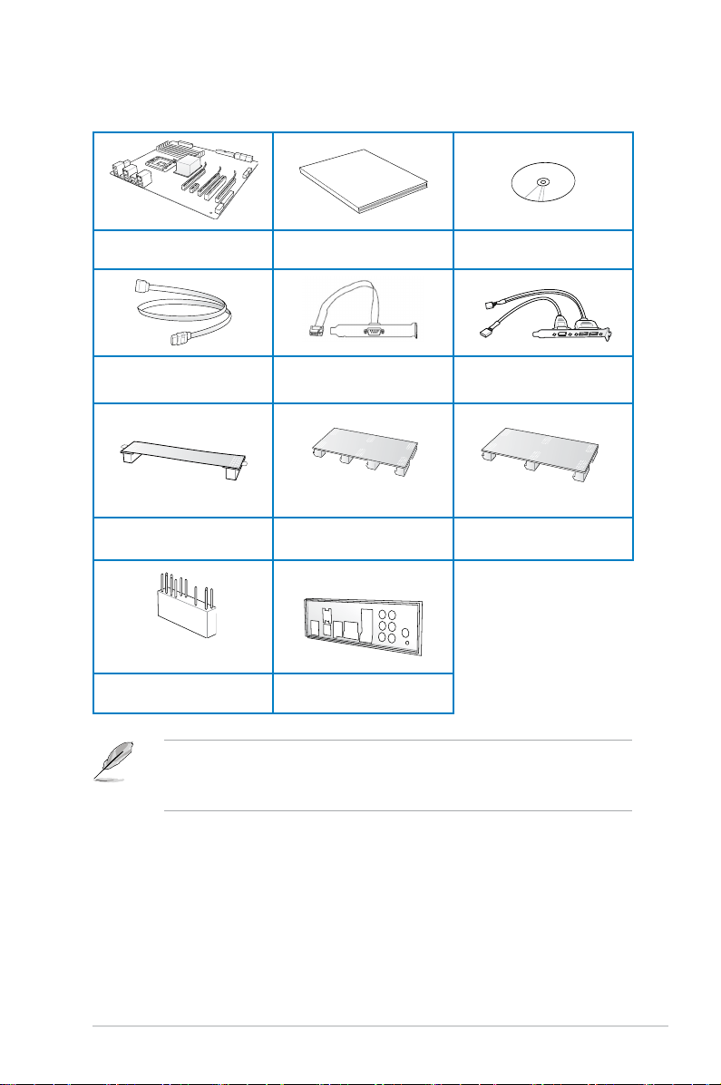
Package contents
Check your motherboard package for the following items
ASUS Z87-WS motherboard User manual Support DVD
10 x Serial ATA 6.0 Gb/s cables COM port bracket
1 x ASUS SLI™ bridge connector
1 x 2-in-1 Q-connector 1 x I/O Shield
1 x ASUS 4-Way SLI™ bridge
connector
• If any of the above items is damaged or missing, contact your retailer.
• The illustrated items above are for reference only. Actual product specications may
vary with different models.
2 USB ports + 1394a cable with
1394 bracket
1 x ASUS 3-Way SLI™ bridge
connector
xv
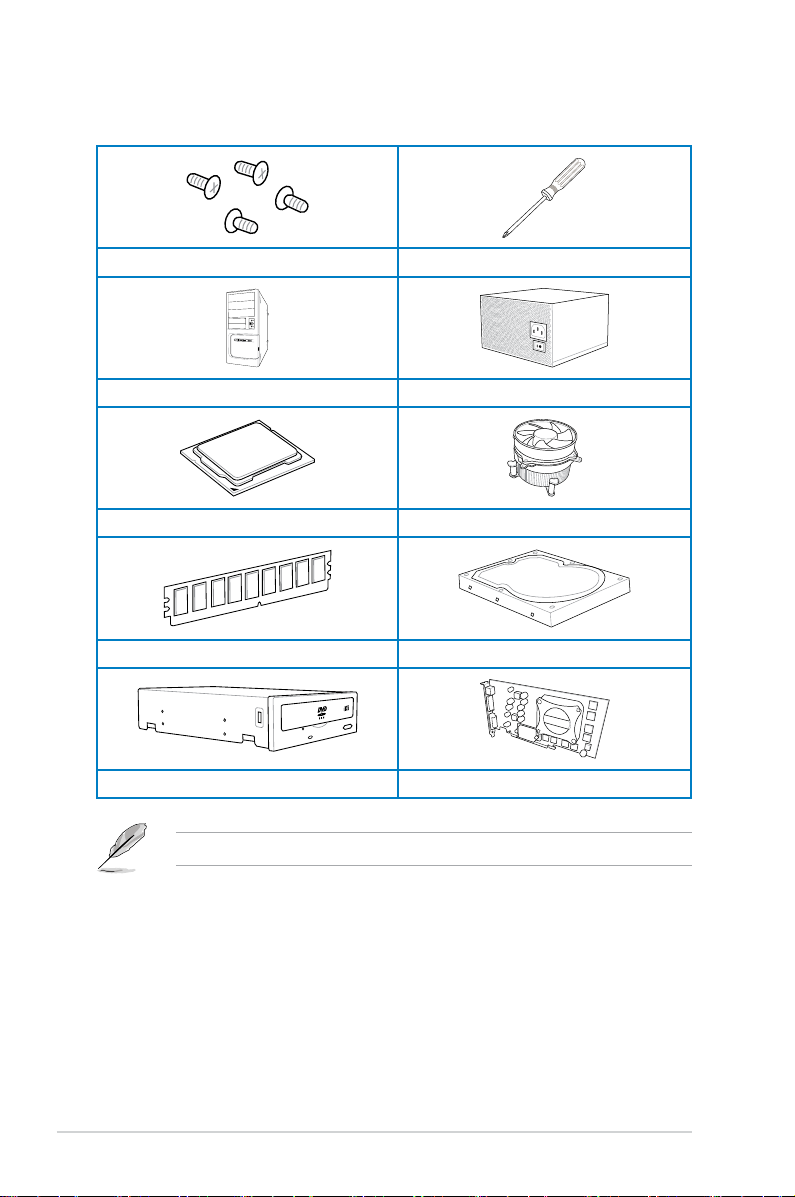
Installation tools and components
1 bag of screws Philips (cross) screwdriver
PC chassis Power supply unit
Intel® LGA1150 CPU Intel® LGA1150 compatible CPU Fan
DIMM SATA hard disk drive
xvi
SATA optical disc drive (optional) Graphics card (optional)
The tools and components in the table above are not included in the motherboard package.

Chapter 1: Product Introduction
Product introduction
1
1.1 Special features
1.1.1 Product highlights
LGA1150 socket for 4th generation Intel® Core™ i7 / Intel® Core™ i5 / Intel®
Core™ i3, Pentium® and Celeron® processors
This motherboard supports 4th generation Intel® Core™ i7 / Intel® Core™ i5 / Intel® Core™ i3,
Pentium®, and Celeron® processors in the LGA1150 package. It provides great graphics and
system performance with its GPU, dual-channel DDR3 memory slots and PCI Express 2.0/3.0
expansion slots.
Intel® Z87 Express Chipset
Intel® Z87 Express Chipset is a single chipset that supports the LGA1150 socket for 4th
generation Intel® Core™ i7 / Intel® Core™ i5 / Intel® Core™ i3, Pentium® and Celeron®
processors. It utilizes serial point-to-point links, which increases bandwidth and enhances
the system’s performance. It natively supports up to six USB 3.0 ports for up to ten times
faster transfer rate than USB 2.0 and enables the iGPU function for Intel
performance.
PCI Express® 3.0
PCI Express® 3.0 (PCIe 3.0) is the PCI Express bus standard that provides twice the
performance and speed of PCIe 2.0. It provides optimal graphics performance, unprecedented
data speed, and seamless transition with its complete backward compatibility to PCIe 1.0/2.0
devices.
Dual-Channel DDR3 2800 (O.C.) / 2666 (O.C.) / 2600 (O.C.) / 2500 (O.C.) / 2400
(O.C.) / 2200 (O.C.) / 2133 (OC.) / 2000 (O.C.) / 1866 (O.C.) / 1800 (O.C.) / 1600 /
1333 MHz Support
The motherboard supports dual-channel DDR3 memory featuring data transfer rates of
DDR3 2800 (O.C.) / 2666 (O.C.) / 2600 (O.C.) / 2500 (O.C.) / 2400 (O.C.) / 2200 (O.C.) /
2133 (OC.) / 2000 (O.C.) / 1866 (O.C.) / 1800 (O.C.) / 1600 / 1333 MHz to boost the system’s
performance, and to meet the higher bandwidth requirements of 3D graphics, multimedia, and
Internet applications.
Quad-GPU SLI and CrossFireX™ Support
This motherboard features the most powerful Intel® Z87 platform that optimizes PCIe
allocation in a multi-GPU SLI or CrossFireX™ solution, giving you a brand-new gaming
enjoyment.
®
integrated graphics
ASUS Z87-WS
Chapter 1
1-1

Intel® Smart Response Technology
Intel® Smart Response Technology, an important part of Green ASUS eco-friendly computing,
reduces load and wait time, eliminates unecessary hard drive spin thus lowering power
usage, and uses an installed SSD (requires 18.6 GB available space) as a cache for
frequently accessed data or applications. It combines SSD performance and hard drive
capacity, operating up to six times faster than a hard-drive-only system to boost the system’s
overall performance.
* 4th Generation Intel® Core™ processors family support Intel® Smart Response Technology.
** An operating system must be installed on the HDD to launch Intel
*** The SSD is reserved for caching function.
®
Smart Response Technology.
Intel® Smart Connect Technology
Your computer can receive fresh updates for selected applications, even when the system
is in sleep mode. This means less time waiting for applications to update and sync with the
cloud, leading to a more efcient computing experience.
Intel® Rapid Start Technology
Intel® Rapid Start Technology allows your system to receive updates for your web
applications in real-time even when your system is in sleep mode, saving wait time and
power usage.
Chapter 1
1-2
Chapter 1: Product introduction

1.1.2 ASUS Workstation Exclusive Features
Best performance for PCI Express 3.0 4-Way CrossFireX™ and SLI™
Native third generation PCI Express x16 4-way AMD CrossFireX™ and NVIDIA® SLI™ offer
the fastest and most reliable graphics performance ever. It’s ideal for professional use in
mechanical, architectural, and interior design, aeronautics, and audiovisual content creation.
Additionally, the ample graphics power can easily run even the most demanding PC games in
full detail for enhanced entertainment.
ASUS Dr. Power: Intelligent power supply monitoring
Power supply health detection helps prevent sudden system shutdown and provides hassle-
free notications should power delivery be insufcient. Additionally, LED messages on the
board clearly indicate any relevant power issues in the event your system fails to boot.
Built-in dual server-class Intel® i210 Ethernet
For more reliable networking, the Z87-WS features the latest server class built-in Intel®
Ethernet adapter. This leads to lower CPU utilization and temperature, outstanding
performance, as well as better support for diverse operating systems.
Beat Thermal Chokes: Better stability and lower power loss
ASUS Beat Thermal Chokes deliver great durability and up to 93% power efciency under
normal operation. A special n design results in 3-50C lower choke temps for added stability,
which is increased exponentially through use of highly conductive and efcient gold-treated
coating. This translates to minimal loss of power delivery.
Extra mSATA 6Gb/s
A built-in mSATA 6Gb/s card provides users diverse storage options. Install your SSD to a
mSATA 6Gb/s port for super-fast boot up and reduced resume times.
Diagnostic LED
Diag. LED checks key components (CPU, memory, graphics card, and hard drive) in
sequence during bootup. If an error is found, the LED next to the relevant device will stay lit
until the problem is solved. This user-friendly design provides an intuitive way to locate the
root problem.
Quick Gate
Quick Gate is a vertical USB connector on the motherboard, allowing you to install USB
devices directly with no messy cables. This stops important data storage devices from
breaking off unexpectedly. P8P67 WS Revolution with this unique design provides a
convenient and safe way to install data and applications on your PC.
ASUS Z87-WS
Chapter 1
1-3

1.1.3 Dual Intelligent Processors 4 with 4-Way Optimization
ASUS Dual Intelligent Processors 4 brings system control solution to a totally whole new
level, combining TPU, EPU, DIGI+ Power Control and Fan Xpert 2 functions to push the
system’s performance to its optimal potential. It automatically pushes or reasonably balances
the system’s performance, power saving levels and fan settings via the user-friendly AI Suite
3 utility.
Digital Power Control
ASUS DIGI+ Power Control features the revolutionary and innovative digital VRM, DRAM,
and CPU Voltage controllers. These controllers offers ultra-precise memory and voltage
tuning for optimal system efciency, stability and performance.
TPU
TPU (Turbo Processing Unit), offers precise voltage control and advanced monitoring
mechanisms through the TurboV functions in your ASUS AI Suite 3 utility.
EPU
EPU (Energy Processing Unit), the world’s rst real-time system power-saving chip,
automatically detects the current system load and intelligently moderates power usage.
It offers a total system-wide energy optimization, reduces fan noise, and extends the
component’s lifespan.
ASUS Fan Xpert 2
ASUS Fan Xpert 2 provides customizable settings for a cooler and quieter computing
environment. With its Fan Auto Tuning feature, ASUS Fan Xpert 2 automatically detects
and tweaks all fan speeds, and provides you with optimized fan settings based on the fans’
specications and positions.
Chapter 1
1-4
Chapter 1: Product introduction

1.1.4 ASUS Exclusive Features
USB 3.0 Boost
ASUS USB 3.0 Boost, which supports USB 3.0 standard UASP (USB Attached SCSI
Protocol), signicantly increases a USB device’s transfer speed up to 170% faster than the
already impressive USB 3.0 transfer speed. It automatically accelerates data speeds for
compatible USB 3.0 peripherals without the need for any user interaction.
USB Charger+
With a dedicated onboard controller, quick-charge all your smart devices such as
smartphones, tablets and more, all up to three times faster, even when the system is
powered off, in sleep or hibernation mode.
USB BIOS Flashback
USB BIOS Flashback offers a hassle-free updating solution for your ultimate convenience.
Connect a USB storage device containing the BIOS le, press the BIOS Flashback button
for about three seconds, and the UEFI BIOS is automatically updated even without entering
the existing BIOS or operating system. It also allows you to regularly check for UEFI BIOS
updates, and download the latest BIOS automatically.
AI Suite 3
With its user-friendly interface, ASUS AI Suite 3 consolidates all the exclusive ASUS features
into one simple-to-use software package. It allows you to supervise overclocking, energy
management, fan speed control, voltage and sensor readings, and even interact with smart
devices via Wi-Fi. This all-in-one software offers diverse and easy to use features with no
need to switch back and forth between different utilities.
ASUS Z87-WS
Chapter 1
1-5

1.1.5 ASUS Quiet Thermal Solution
ASUS Fanless Design - Heat-sink solution
The stylish heatsink features a 0-dB thermal solution that offers you a noiseless PC
environment. The heatsink design also lowers the temperature of the chipset and power
phase area through highly efcient heat-exchange. Combined with usability and aesthetics,
the ASUS stylish heatsink will give you an extremely silent and cooling experience with its
elegant appearance.
1.1.6 ASUS EZ DIY
ASUS UEFI BIOS (EZ Mode)
ASUS UEFI BIOS, a UEFI compliant architecture, offers the rst mouse-controlled intuitive
graphical BIOS interface that goes beyond the traditional keyboard-only BIOS controls,
providing you with more exibility, convenience, and easy to navigate UEFI BIOS than the
traditional BIOS versions. It offers dual modes and native support for hard drives larger than
2.2 TB.
ASUS UEFI BIOS includes the following new features:
• New My Favorite function allows you to quickly access frequently used items
• New Quick Note function allows you to take notes in the BIOS environment
• New log reminder allows you to view all your modied settings
• F12 BIOS snapshot hotkey
• F3 Shortcut for most accessed information
• ASUS DRAM SPD (Serial Presence Detect) information detecting faulty DIMMs, and
helping with difcult POST situations.
ASUS Q-connector
ASUS Q-Connector is a unique adapter that allows you to easily connect or disconnect the
chassis front panel cables to one module, eliminating the hassle of plugging one cable at a
time and making the connection quick and accurate.
Chapter 1
1-6
Chapter 1: Product introduction

1.1.7 Other special features
DTS Connect
To get the most out of your audio entertainment across all formats and quality levels,
DTS Connect combines two technologies, DTS Neo:PC™ upmixes stereo sources (CDs,
MP3s, WMAs, Internet radio) into as many as 7.1 channels of incredible surround sound.
Consumers can connect their PC to a home theater system. DTS Interactive is capable of
performing mult-channel encoding of DTS bitstreams on personal computers, and sending
encoded bitstreams out of a digital audio connection (such as S/PDIF or HDMI) designed to
deliver audio to an external decoder.
DTS UltraPC II
DTS UltraPC II delivers a superior surround sound experience through your system’s
speakers and headphones while monitoring and balancing the loudness level difference
between digital audio formats. It also enhances audio settings by augmenting low and high
frequencies of musical tones, restores compressed or re-mastered sounds, improves bass
performance even without a subwoofer, and improves dialogue derived from DVD or Blu-ray
Disc™.
ErP Ready
The motherboard is European Union’s Energy-related Products (ErP) ready, and ErP requires
products to meet certain energy efciency requirement in regards to energy consumption.
This is in line with the ASUS vision of creating environment-friendly and energy-efcient
products through product design and innovation to reduce carbon footprint of the product and
thus mitigate environmental impacts.
ASUS Z87-WS
Chapter 1
1-7

1.2 Motherboard overview
1.2.1 Before you proceed
Take note of the following precautions before you install motherboard components or change
any motherboard settings.
• Unplug the power cord from the wall socket before touching any component.
• Before handling components, use a grounded wrist strap or touch a safely grounded
object or a metal object, such as the power supply case, to avoid damaging them due
to static electricity.
• Hold components by the edges to avoid touching the ICs on them.
• Whenever you uninstall any component, place it on a grounded antistatic pad or in the
bag that came with the component.
• Before you install or remove any component, ensure that the ATX power supply is
switched off or the power cord is detached from the power supply. Failure to do so
may cause severe damage to the motherboard, peripherals, or components.
Chapter 1
1-8
Chapter 1: Product introduction
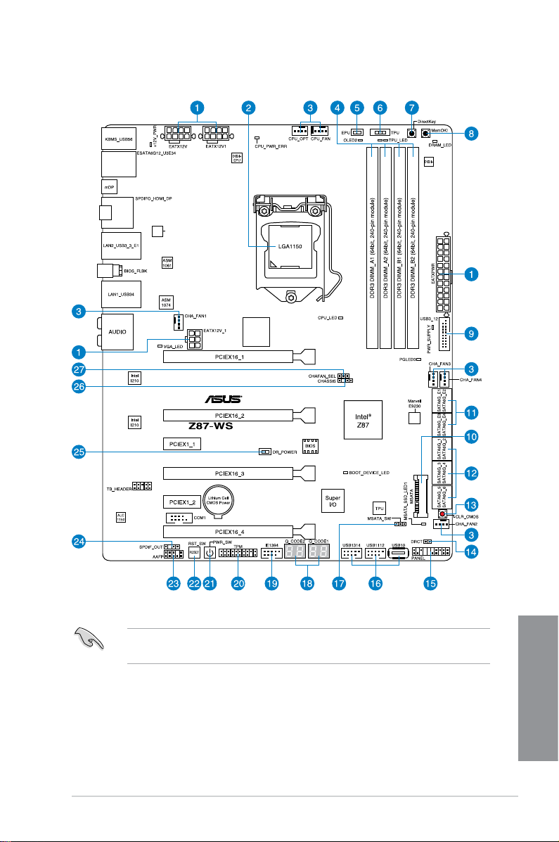
1.2.2 Motherboard layout
Parade
PS8201
PLX
PEX8747
Refer to 1.2.6 Internal connectors and 2.3.1 Rear I/O connection for more information
about rear panel connectors and internal connectors.
ASUS Z87-WS
Chapter 1
1-9

Layout contents
Connectors/Jumpers/Slots Page
1. ATX power connectors
(24-pin EATXPWR; 8-pin EATX12V1, 8-pin EATX12V; 6-pin
EATX12V_1)
2. LGA1150 CPU socket
3. CPU, chassis, and power fan connectors
(4-pin CPU_FAN, 4-pin CPU_OPT, 4-pin CHA_FAN1~4 )
4. DDR3 DIMM slots
5. EPU switch
6. TPU switch
7. DirectKey
8. MemOK! button
9. USB 3.0 connector (20-1 pin USB3_12)
10. mSATA connector
11. Marvell 9230 ATA 6.0 Gb/s connectors
(7-pin SATA6G_E1234 [dark brown])
®
12. Intel
13. Clear CMOS button
14. Direct connector (2-pin DRCT)
15. System panel connector (20-8 pin PANEL)
16. USB 2.0 connectors (10-1 pin USB1112, USB1314; USB10)
17. mSATA_SW
18. Q-Code LED
19. IEEE 1394 port connector (10-1 pin IE1394)
20. TPM connector (20-1 pin TPM)
21. Power-on button
22. Reset button
23. Front panel audio connector (10-1 pin AAFP)
24. Digital audio connector (4-1 pin SPDIF_OUT)
25. ASUS Dr. POWER switch
Z87 Serial ATA 6.0 Gb/s connectors (7-pin SATA6G_1~6 [yellow]) 1-31
1-37
1-11
1-35
1-12
1-21
1-20
1-19
1-18
1-33
1-40
1-32
1-21
1-19
1-38
1-34
1-22
1-24
1-33
1-39
1-17
1-22
1-36
1-32
1-17
Chapter 1
1-10
Chapter 1: Product introduction
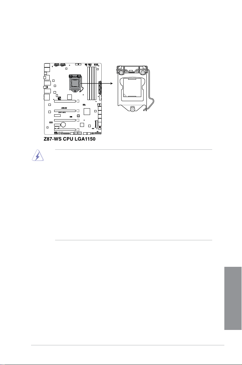
1.2.3 Central Processing Unit (CPU)
The motherboard comes with a surface mount LGA1150 socket designed for the 4th
Generation Intel® Core™ i7 / Intel® Core™ i5 / Intel® Core™ i3, Pentium® and Celeron®
processors.
• Ensure that all power cables are unplugged before installing the CPU.
• Ensure that you install the correct CPU designed for LGA1150 only. DO NOT install a
CPU designed for LGA1155 and LGA1156 sockets on the LGA1150 socket.
• Upon purchase of the motherboard, ensure that the PnP cap is on the socket and
the socket contacts are not bent. Contact your retailer immediately if the PnP cap
is missing, or if you see any damage to the PnP cap/socket contacts/motherboard
components. ASUS will shoulder the cost of repair only if the damage is shipment/
transit-related.
• Keep the cap after installing the motherboard. ASUS will process Return Merchandise
Authorization (RMA) requests only if the motherboard comes with the cap on the
LGA1150 socket.
• The product warranty does not cover damage to the socket contacts resulting from
incorrect CPU installation/removal, or misplacement/loss/incorrect removal of the PnP
cap.
ASUS Z87-WS
Chapter 1
1-11

1.2.4 System memory
The motherboard comes with four Double Data Rate 3 (DDR3) Dual Inline Memory Modules
(DIMM) slots.
A DDR3 module is notched differently from a DDR or DDR2 module. DO NOT install a DDR
or DDR2 memory module to the DDR3 slot.
Recommended memory congurations
Chapter 1
1-12
Chapter 1: Product introduction

Memory congurations
You may install 2GB, 4GB and 8GB unbuffered and non-ECC DDR3 DIMMs into the DIMM
sockets.
• You may install varying memory sizes in Channel A and Channel B. The system maps
the total size of the lower-sized channel for the dual-channel conguration. Any excess
memory from the higher-sized channel is then mapped for single-channel operation.
• According to Intel
protect the CPU.
• Always install DIMMs with the same CAS latency. For optimum compatibility, we
recommend that you obtain memory modules from the same vendor.
• Due to the memory address limitation on 32-bit Windows
or more memory on the motherboard, the actual usable memory for the OS can be
about 3GB or less. For effective use of memory, we recommend that you do any of the
following:
a) Use a maximum of 3GB system memory if you are using a 32-bit Windows
b) Install a 64-bit Windows
motherboard.
c) For more details, refer to the Microsoft
com/kb/929605/en-us.
• This motherboard does not support DIMMs made up of 512Mb (64MB) chips or less
(Memory chip capacity counts in Megabit, 8 Megabit/Mb = 1 Megabyte/MB).
• The default memory operation frequency is dependent on its Serial Presence Detect
(SPD), which is the standard way of accessing information from a memory module.
Under the default state, some memory modules for overclocking may operate at a
lower frequency than the vendor-marked value. To operate at the vendor-marked
value or at a higher frequency, refer to section 3.5 Ai Tweaker menu for manual
memory frequency adjustment.
• For system stability, use a more efcient memory cooling system to support a full
memory load (4 DIMMs) or overclocking condition.
• Memory modules with memory frequency higher than 2133MHz and their
corresponding timing or the loaded XMP prole is not the JEDEC memory standard.
The stability and compatibility of the memory modules depend on the CPU’s
capabilities and other installed devices.
• Always install DIMMS with the same CAS Latency. For optimum compatibility, we
recommend that you install memory modules of the same version or data code (D/C)
from the same vendor. Check with the vendor to get the correct memory modules.
®
CPU spec, a DIMM voltage below 1.65V is recommended to
®
OS, when you install 4GB
®
®
OS when you want to install 4GB or more on the
®
support site at http://support.microsoft.
OS.
ASUS Z87-WS
Chapter 1
1-13

Z87-WS Motherboard Qualied Vendors List (QVL)
Visit the ASUS website for the latest QVL.
Chapter 1
1-14
Chapter 1: Product introduction

1.2.5 Expansion slots
Unplug the power cord before adding or removing expansion cards. Failure to do so may
cause you physical injury and damage motherboard components.
Slot No. Slot Description
1 PCIe 3.0/2.0 x16_1 slot (single at x16 or dual at x8/x8 mode)
2 PCIe 3.0/2.0 x16_2 slot (at x8 mode)
3 PCIe 2.0 x1_1 slot
4 PCIe 3.0/2.0 x16_3 slot (single at x16 or dual at x8/x8 mode)
5 PCIe 2.0 x1_2 slot
6 PCIe 3.0/2.0 x16_4 slot (at x8 mode)
PCIE x16_1 auto switches to x8 when slot PCIE x16_2 is occupied; PCIE x16_2 auto
switches to x4 when slot PCIE x16_4 is occupied.
ASUS Z87-WS
Chapter 1
1-15

Slot
no.
1
2 — — x8 x8
4 —
6 — — — x8
IRQ assignments for this motherboard
PCIe x16_1 shared – – – – – – –
PCIe x16_2 shared – – – – – – –
PCIe x16_3 shared – – – – – – –
PCIe x16_4 shared – – – – – – –
PCIe x1_1 – – – shared – – – –
PCIe x1_2 shared – – – – – – –
Marvell 9230 shared – – – – – – –
ASM1061 – shared – – – – – –
VIA1394 – – shared – – – – –
USB 3.0 – – – – – shared – –
LAN1 (I210) – – shared – – – – –
Chapter 1
LAN2 (I210) – – – shared – – – –
SATA Controller 1 – – – – shared – – –
SATA Controller 2 – – – – shared – – –
USB 2.0 Controller 1 – – – – – – – shared
USB 2.0 Controller 2 – – – – shared – – –
HD Audio – – – – – – shared –
PCIe Express 3.0 operating mode
Single VGA
x16
(single VGA recommended)
• We recommend that you provide sufcient power when running CrossFireX™ or SLI™
mode.
• Connect a chassis fan to the motherboard connector labeled CHA_FAN1-4 when
using multiple graphics cards for better thermal environment.
• We recommend you connect an EATX 12V_1 cable when running CrossFireX and
SLI.
SLI
CrossFireX
x16 x8 x8
x16
(dual VGA
recommended)
3-WAY SLI
CrossFireX
x16 x8
4-WAY SLI
CrossFireX
A B C D E F G H
1-16
Chapter 1: Product introduction

1.2.6 Onboard buttons and switches
Onboard switches and buttons allow you to ne-tune performance when working on a bare or
open-case system. This is ideal for overclockers and gamers who continually change settings
to enhance system performance.
1. Power-on button
The motherboard comes with a power-on button that allows you to power up or wake
up the system. The button also lights up when the system is plugged to a power source
indicating that you should shut down the system and unplug the power cable before
removing or installing any motherboard component.
2. ASUS Dr. POWER switch
This switch allows you to enable or disable the ASUS Dr. Power feature. Install the
bundled ASUS Dr. Power Utility then enable this switch to allow the system to display
notication messages in your Windows screen if a problem is detected with your Power
Supply Unit (PSU).
ASUS Z87-WS
Chapter 1
1-17

3. MemOK! button
Installing DIMMs that are not compatible with the motherboard may cause system boot
failure, and the DRAM_LED near the MemOK! to switch lights continuously. Press
and hold the MemOK! button until the DRAM_LED starts blinking to begin automatic
memory compatibility tuning for successful boot.
Chapter 1
• Refer to section 1.2.8 Onboard LEDs for the exact location of the DRAM_LED.
• The DRAM_LED also lights up when the DIMM is not properly installed. Turn off the
system and reinstall the DIMM before using the MemOK! function.
• The MemOK! switch does not function under a Windows
• During the tuning process, the system loads and tests failsafe memory settings. It
takes about 30 seconds for the system to test one set of failsafe settings. If the test
fails, the system reboots and test the next set of failsafe settings. The blinking speed
of the DRAM_LED increases, indicating different test processes.
• Due to memory tuning requirements, the system automatically reboots when
each timing set is tested. If the installed DIMMs still fail to boot after the whole
tuning process, the DRAM_LED lights continuously. Replace the DIMMs with ones
recommended in the Memory QVL (Qualied Vendors Lists) in this user manual or on
the ASUS website at www.asus.com.
• If you turn off the computer and replace DIMMs during the tuning process, the system
continues memory tuning after turning on the computer. To stop memory tuning, turn
off the computer and unplug the power cord for about 5–10 seconds.
• If your system fails to boot up due to BIOS overclocking, press the MemOK! switch
to boot and load the BIOS default settings. A message will appear during POST
reminding you that the BIOS has been restored to its default settings.
• We recommend that you download and update to the latest BIOS version from the
ASUS website at www.asus.com after using the MemOK! function.
®
OS environment.
1-18
Chapter 1: Product introduction

4. DirectKey button
This feature allows your system to go to the BIOS Setup program with the press of
a button. With DirectKey, you can enter the BIOS anytime without having to press
the <Del> key during POST. It also allows you to turn on or turn off your system and
conveniently enter the BIOS during boot-up.
Ensure to save your data before using the DirectKey button.
• When the system is on and you press the DirectKey button, your system will shut
down. Press the DirectKey button again or the Power-on button to reboot and enter
the BIOS directly.
• Turn off your system using the power-on button to allow your system to go through
POST (without entering the BIOS) when you reboot your system.
• Refer to section
function.
3.8 Boot Menu for details about setting the DirectKey default
ASUS Z87-WS
Chapter 1
1-19

5. TPU switch
With its two-level adjustment functions, the TPU allows you to automatically adjust the
CPU ratio and clock speed for optimal system performance.
• Enable this switch when the system is powered off.
• When the TPU switch is set to Enabled (TPU_I: CPU Ratio Boost), the system
automatically adjusts the CPU ratio for enhanced performance.
• When the TPU switch is set to Enabled (TPU_II: CPU BCLK and Ratio Boost), the
system automatically adjusts the base clock rate (BLCK) and the CPU ratio for
enhanced performance.
• The TPU LED (TPU_LED) near the TPU switch lights up when the TPU switch is
enabled. Refer to section 1.2.7 Onboard LEDs for the exact location of the TPU LED.
• If you enable this switch under a Windows
activated after the next system bootup.
• You may use the 4-Way Optimization and TPU feature in the AI Suite 3 application,
adjust the BIOS setup program, or enable the TPU switch at the same time. However,
the system will use the last setting you have made.
®
OS environment, the TPU function will be
Chapter 1
1-20
Chapter 1: Product introduction

6. EPU switch
Enable this switch to automatically detect the current PC loading and intelligently
moderate power consumption.
Enable this switch when the system is powered off.
• The EPU LED (OLED2) near the EPU switch lights up when the EPU switch is
enabled. Refer to section 1.2.7 Onboard LEDs for the exact location of the EPU LED.
• If you enable this switch under a Windows
activated after the next system bootup.
• You may change the EPU settings in the software application or BIOS setup program
and enable the EPU function at the same time. However, the system will use the last
setting you have made.
®
OS environment, the EPU function will be
7. Clear CMOS button
Press the Clear CMOS switch to clear BIOS setup information only when the system
hangs due to overclocking.
ASUS Z87-WS
Chapter 1
1-21

8. Reset button
Auto-detect
mSATA or
SATA port 6
Force
mSATA
function
Press the reset button to reboot the system.
9. MSATA switch
The mSATA switch congures mSATA support for the motherboard.
Chapter 1
1-22
Chapter 1: Product introduction
1.2.7 Onboard LEDs
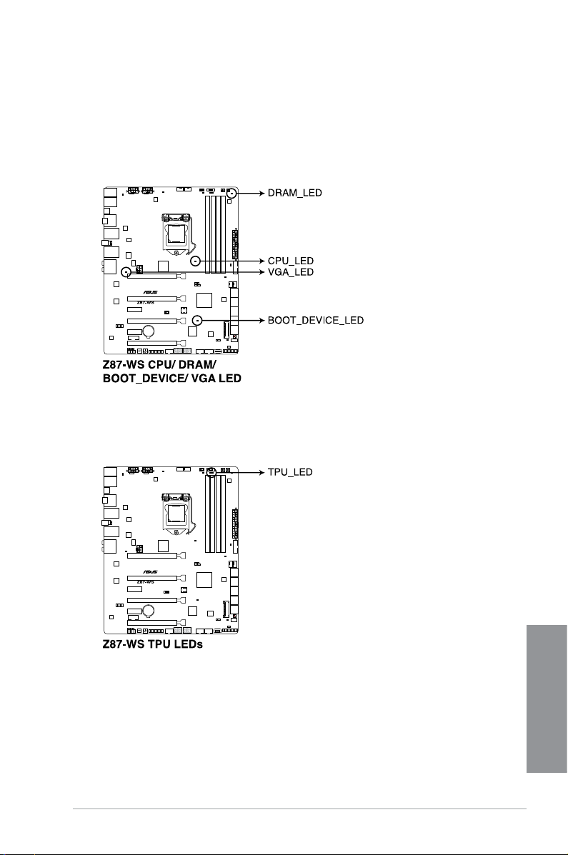
1. POST State LEDs
The POST State LEDs provide the status of these key components during POST
(Power-On-Self Test): CPU, memory modules, VGA card, and hard disk drives If an
error is found, the critical component’s LED stays lit until the problem is solved.
2. TPU LED
The TPU LED lights up when the TPU switch is enabled.
ASUS Z87-WS
Chapter 1
1-23
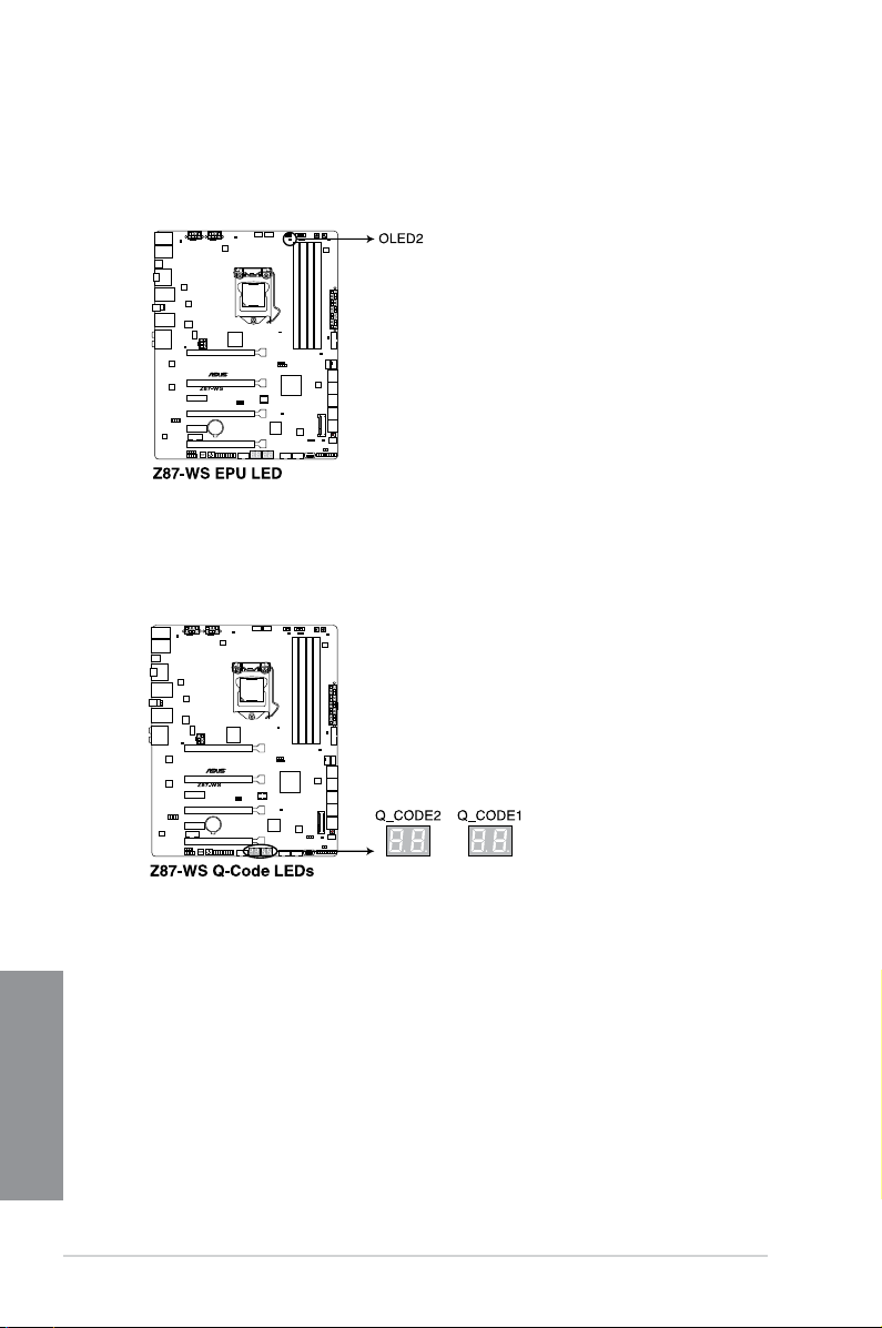
3. EPU LED
The EPU LED lights up when the EPU switch is enabled.
4. Q-Code LED
The Q-Code LED provides you with a 2-digit error code that displays the system status.
Refer to the Q-Code table on the next page for details.
Chapter 1
1-24
Chapter 1: Product introduction

Q-Code table
Code Description
00 Not used
01 Power on. Reset type detection (soft/hard).
02 AP initialization before microcode loading
03 System Agent initialization before microcode loading
04 PCH initialization before microcode loading
06 Microcode loading
07 AP initialization after microcode loading
08 System Agent initialization after microcode loading
09 PCH initialization after microcode loading
0B Cache initialization
0C – 0D Reserved for future AMI SEC error codes
0E Microcode not found
0F Microcode not loaded
10 PEI Core is started
11 – 14 Pre-memory CPU initialization is started
15 – 18 Pre-memory System Agent initialization is started
19 – 1C Pre-memory PCH initialization is started
2B – 2F Memory initialization
30 Reserved for ASL (see ASL Status Codes section below)
31 Memory Installed
32 – 36 CPU post-memory initialization
37 – 3A Post-Memory System Agent initialization is started
3B – 3E Post-Memory PCH initialization is started
4F DXE IPL is started
50 – 53
54 Unspecied memory initialization error
55 Memory not installed
56 Invalid CPU type or Speed
57 CPU mismatch
58 CPU self test failed or possible CPU cache error
59 CPU micro-code is not found or micro-code update is failed
Memory initialization error. Invalid memory type or incompatible memory
speed
(continued on the next page)
Chapter 1
ASUS Z87-WS
1-25

Code Description
5A Internal CPU error
5B Reset PPI is not available
5C – 5F Reserved for future AMI error codes
E0 S3 Resume is stared (S3 Resume PPI is called by the DXE IPL)
E1 S3 Boot Script execution
E2 Video repost
E3 OS S3 wake vector call
E4 – E7 Reserved for future AMI progress codes
E8 S3 Resume Failed
E9 S3 Resume PPI not Found
EA S3 Resume Boot Script Error
EB S3 OS Wake Error
EC – EF Reserved for future AMI error codes
F0 Recovery condition triggered by rmware (Auto recovery)
F1 Recovery condition triggered by user (Forced recovery)
F2 Recovery process started
F3 Recovery rmware image is found
F4 Recovery rmware image is loaded
F5 – F7 Reserved for future AMI progress codes
F8 Recovery PPI is not available
F9 Recovery capsule is not found
FA Invalid recovery capsule
FB – FF Reserved for future AMI error codes
60 DXE Core is started
61 NVRAM initialization
62 Installation of the PCH Runtime Services
Chapter 1
63 – 67 CPU DXE initialization is started
68 PCI host bridge initialization
69 System Agent DXE initialization is started
6A System Agent DXE SMM initialization is started
6B – 6F System Agent DXE initialization (System Agent module specic)
1-26
(continued on the next page)
Chapter 1: Product introduction

Code Description
70 PCH DXE initialization is started
71 PCH DXE SMM initialization is started
72 PCH devices initialization
73 – 77 PCH DXE Initialization (PCH module specic)
78 ACPI module initialization
79 CSM initialization
7A – 7F Reserved for future AMI DXE codes
90 Boot Device Selection (BDS) phase is started
91 Driver connecting is started
92 PCI Bus initialization is started
93 PCI Bus Hot Plug Controller Initialization
94 PCI Bus Enumeration
95 PCI Bus Request Resources
96 PCI Bus Assign Resources
97 Console Output devices connect
98 Console input devices connect
99 Super IO Initialization
9A USB initialization is started
9B USB Reset
9C USB Detect
9D USB Enable
9E – 9F Reserved for future AMI codes
A0 IDE initialization is started
A1 IDE Reset
A2 IDE Detect
A3 IDE Enable
A4 SCSI initialization is started
A5 SCSI Reset
A6 SCSI Detect
A7 SCSI Enable
A8 Setup Verifying Password
(continued on the next page)
Chapter 1
ASUS Z87-WS
1-27

Code Description
A9 Start of Setup
AA Reserved for ASL (see ASL Status Codes section below)
AB Setup Input Wait
AC Reserved for ASL (see ASL Status Codes section below)
AD Ready To Boot event
AE Legacy Boot event
AF Exit Boot Services event
B0 Runtime Set Virtual Address MAP Begin
B1 Runtime Set Virtual Address MAP End
B2 Legacy Option ROM Initialization
B3 System Reset
B4 USB hot plug
B5 PCI bus hot plug
B6 Clean-up of NVRAM
B7 Conguration Reset (reset of NVRAM settings)
B8– BF Reserved for future AMI codes
D0 CPU initialization error
D1 System Agent initialization error
D2 PCH initialization error
D3 Some of the Architectural Protocols are not available
D4 PCI resource allocation error. Out of Resources
D5 No Space for Legacy Option ROM
D6 No Console Output Devices are found
D7 No Console Input Devices are found
D8 Invalid password
D9 Error loading Boot Option (LoadImage returned error)
Chapter 1
DA Boot Option is failed (StartImage returned error)
DB Flash update is failed
DC Reset protocol is not available
1-28
Chapter 1: Product introduction

ACPI/ASL Checkpoints
Code Description
01 System is entering S1 sleep state
02 System is entering S2 sleep state
03 System is entering S3 sleep state
04 System is entering S4 sleep state
05 System is entering S5 sleep state
10 System is waking up from the S1 sleep state
20 System is waking up from the S2 sleep state
30 System is waking up from the S3 sleep state
40 System is waking up from the S4 sleep state
AC System has transitioned into ACPI mode. Interrupt controller is in PIC mode.
AA System has transitioned into ACPI mode. Interrupt controller is in APIC mode.
5. PWR_SUPPLY LED
The ASUS Dr. Power LED near the EATX PWR connector lights up when the ASUS Dr.
Power switch setting is on Enable and the power supply unit has failed.
ASUS Z87-WS
Chapter 1
1-29

6. PGLED3 LED
The ASUS Dr. Power LED near the ASUS Dr. Power switch lights up when the ASUS
Dr. Power switch is on Enable.
7. +12V_PWR LED
The ASUS Dr. Power LED near EATX12V connector lights up when the ASUS Dr.
Power switch setting is on enable and there is no power detected going into the
processor.
Chapter 1
1-30
Chapter 1: Product introduction

1.2.8 Internal connectors
1. Intel® Z87 Serial ATA 6.0 Gb/s connectors (7-pin SATA6G_1-6 [yellow])
These connectors connect to Serial ATA 6.0 Gb/s hard disk drives via Serial ATA 6.0
Gb/s signal cables.
If you installed Serial ATA hard disk drives, you can create a RAID 0, 1, 5, and 10
conguration with the Intel® Rapid Storage Technology through the onboard Intel® Z87
chipset.
• These connectors are set to [AHCI Mode] by default. If you intend to create a Serial
• Before creating a RAID set, refer to section
ASUS Z87-WS
ATA RAID set using these connectors, set the SATA Mode item in the BIOS to [RAID
Mode]. Refer to section 3.6.3 SATA Conguration for details.
5.1 RAID congurations or the manual
bundled in the motherboard support DVD.
Chapter 1
1-31

2. Marvell 9230 ATA 6.0 Gb/s connectors (7-pin SATA6G_E1234 [dark brown])
Z87-WS Marvell SATA 6.0 Gb/s connectors
These connectors connect to Serial ATA 6.0 Gb/s hard disk drives via Serial ATA 6.0
Gb/s signal cables.
• Marvell storage controller can only support AHCI mode.
• These SATA ports are for data drives only.
3. Digital audio connector (4-1 pin SPDIF_OUT)
This connector is for an additional Sony/Philips Digital Interface (S/PDIF) port. Connect
the S/PDIF Out module cable to this connector, then install the module to a slot
opening at the back of the system chassis.
Chapter 1
The S/PDIF module is purchased separately.
1-32
Chapter 1: Product introduction

4. USB 3.0 connector (20-1 pin USB3_12)
This connector allows you to connect a USB 3.0 module for additional USB 3.0 front
or rear panel ports. With an installed USB 3.0 module, you can enjoy all the benets of
USB 3.0 including faster data transfer speeds of up to 5Gbps, faster charging time for
USB-chargeable devices, optimized power efciency, and backward compatibility with
USB 2.0.
• The USB 3.0 module is purchased separately.
• These connectors are based on xHCI specication. We recommend you to install the
related driver to fully use the USB 3.0 ports under Windows® 7.
• The plugged USB 3.0 device may run on xHCI or EHCI mode depending on the
operating system’s setting.
5. IEEE 1394 port connector (10-1 pin IE1394)
This connector is for an IEEE 1394 port. Connect the IEEE 1394 module cable to this
connector, then install the module to a slot opening at the back of the system chassis.
ASUS Z87-WS
Chapter 1
1-33

6. USB 2.0 connectors (10-1 pin USB1112, USB1314; USB10)
These connectors are for USB 2.0 ports. Connect the USB module cable to any of
these connectors, then install the module to a slot opening at the back of the system
chassis. These USB connectors comply with USB 2.0 specication that supports up to
480 MBps connection speed.
DO NOT connect a 1394 cable to the USB connectors. Doing so will damage the
motherboard!
You can connect the front panel USB cable to the ASUS Q-Connector (USB, dark brown)
rst, and then install the Q-Connector (USB) to the USB connector onboard if your chassis
supports front panel USB ports.
Chapter 1
1-34
• The USB 2.0 module is purchased separately.
• These connectors are based on xHCI specication. We recommend you to install the
related driver to fully use the USB 2.0 ports under Windows® 7.
Chapter 1: Product introduction

7. CPU, chassis, and optional fan connectors
(4-pin CPU_FAN; 4-pin CPU_OPT; 4-pin CHA_FAN1~4)
Connect the fan cables to the fan connectors on the motherboard, ensuring that the
black wire of each cable matches the ground pin of the connector.
• DO NOT forget to connect the fan cables to the fan connectors. Insufcient air ow
inside the system may damage the motherboard components. These are not jumpers!
Do not place jumper caps on the fan connectors!
• Ensure that the CPU fan is securely installed to the CPU fan connector.
• The CPU_FAN connector supports the CPU fan of maximum 1A (12 W) fan power.
• The CPU_FAN connector and CHA_FAN connectors support the ASUS FAN Xpert 2
ASUS Z87-WS
feature.
Chapter 1
1-35

8. Front panel audio connector (10-1 pin AAFP)
This connector is for a chassis-mounted front panel audio I/O module that supports
either HD Audio or legacy AC`97 audio standard. Connect one end of the front panel
audio I/O module cable to this connector.
• We recommend that you connect a high-denition front panel audio module to this
connector to avail of the motherboard’s high-denition audio capability.
• If you want to connect a high-denition or an AC’97 front panel audio module to this
connector, set the Front Panel Type item in the BIOS setup to [HD] or [AC97].
Chapter 1
1-36
Chapter 1: Product introduction
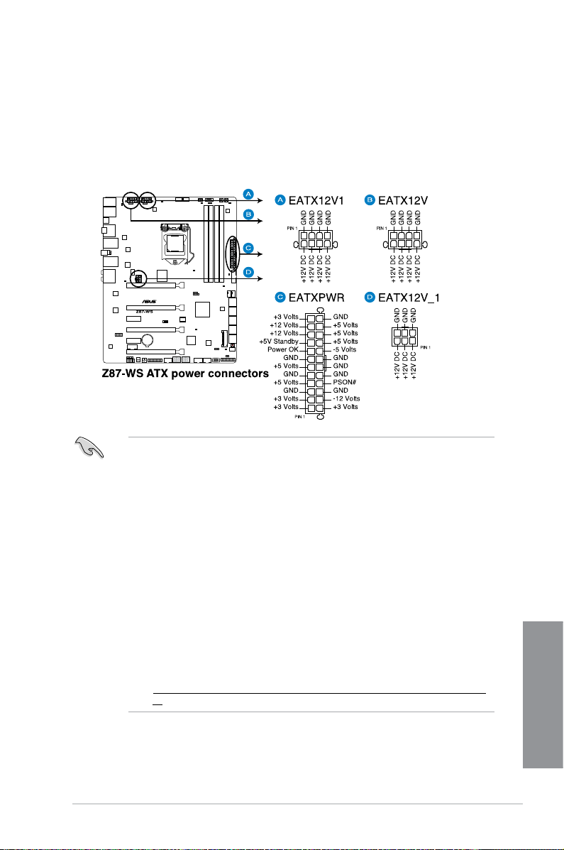
9. EATX power connectors
(24-pin EATXPWR; 8-pin EATX12V1, 8-pin EATX12V; 6-pin EATX12V_1)
These connectors are for ATX power supply plugs. The power supply plugs are
designed to t these connectors in only one orientation. Find the proper orientation and
push down rmly until the connectors completely t.
• For a fully congured system, we recommend that you use a power supply unit
(PSU) that complies with ATX 12 V Specication 2.0 (or later version) and provides a
minimum power of 350 W.
• DO NOT forget to connect the 4-pin/8-pin EATX12 V power plug. Otherwise, the
system will not boot.
• We recommend you use an EATX12V power connector to increase power efciency
when you overclock the CPU.
• We recommend that you use a PSU with a higher power output when conguring a
system with more power-consuming devices. The system may become unstable or
may not boot up if the power is inadequate.
• If you want to use two or more high-end PCI Express x16 cards, use a PSU with
1000W power or above to ensure the system stability.
• We recommend you connect an EATX 12V_1 cable to increase power efciency when
you plug in high-end PCI Express x16 cards.
• If you are uncertain about the minimum power supply requirement for your system,
refer to the Recommended Power Supply Wattage Calculator at
http://support.asus.com/PowerSupplyCalculator/PSCalculator.aspx?SLanguage=enus
ASUS Z87-WS
Chapter 1
1-37

10. System panel connector (20-8 pin PANEL)
This connector supports several chassis-mounted functions.
• System power LED (2-pin PLED)
This 2-pin connector is for the system power LED. Connect the chassis power LED
cable to this connector. The system power LED lights up when you turn on the system
power, and blinks when the system is in sleep mode.
• Hard disk drive activity LED (2-pin HDD_LED)
This 2-pin connector is for the HDD Activity LED. Connect the HDD Activity LED cable
to this connector. The HDD LED lights up or ashes when data is read from or written
to the HDD.
• System warning speaker (4-pin SPEAKER)
This 4-pin connector is for the chassis-mounted system warning speaker. The speaker
allows you to hear system beeps and warnings.
• ATX power button/soft-off button (2-pin PWRSW)
This connector is for the system power button. Pressing the power button turns the
system on or puts the system in sleep or soft-off mode depending on the operating
system settings. Pressing the power switch for more than four seconds while the
system is ON turns the system OFF.
• Reset button (2-pin RESET)
This 2-pin connector is for the chassis-mounted reset button for system reboot without
turning off the system power.
Chapter 1
1-38
Chapter 1: Product introduction

11. TPM connector (20-1 pin TPM)
This connector supports a Trusted Platform Module (TPM) system, which securely
store keys, digital certicates, passwords and data. A TPM system also helps enhance
network security, protect digital identities, and ensures platform integrity.
12. Direct Connector (2-pin DRCT)
This connector is for the chassis-mounted button that supports the DirectKey function.
Connect the button cable that supports DirectKey, from the chassis to this connector on
the motherboard.
Ensure that your chassis comes with the extra button cable that supports the DirectKey
feature. Refer to the technical documentation that came with the chassis for details.
ASUS Z87-WS
Chapter 1
1-39

13. mSATA connector
This connector is for a single SATA 6.0Gb/s Solid-State Drive (SSD). Connect the SSD
to the mSATA port.
14. Chassis intrusion connector (4-1 pin CHASSIS)
This connector is for a chassis-mounted intrusion detection sensor or switch. Connect
one end of the chassis intrusion sensor or switch cable to this connector. The chassis
intrusion sensor or switch sends a high-level signal to this connector when a chassis
component is removed or replaced. The signal is then generated as a chassis intrusion
event.
By default, the pin labeled “Chassis Signal” and “Ground” are shorted with a jumper
cap. Remove the jumper caps only when you intend to use the chassis intrusion
detection feature.
Chapter 1
1-40
Chapter 1: Product introduction

Chapter 2: Basic installation
Basic installation
2.1 Building your PC system
2.1.1 Motherboard installation
The diagrams in this section are for reference only. The motherboard layout may vary with
models, but the installation steps are the same for all models.
1. Install the ASUS I/O Shield to the chassis rear I/O panel.
2
2. Place the motherboard into the chassis, ensuring that its rear I/O ports are aligned to
the chassis’ rear I/O panel.
ASUS Z87-WS
Chapter 2
2-1

3. Place nine screws into the holes indicated by circles to secure the motherboard to the
chassis.
Chapter 2
2-2
DO NOT overtighten the screws! Doing so can damage the motherboard.
Chapter 2: Basic installation

2.1.2 CPU installation
Ensure that you install the correct CPU designed for LGA1150 socket only. DO NOT install
a CPU designed for LGA155 and LGA1156 socket on the LGA1150 socket.
ASUS Z87-WS
Chapter 2
2-3

2.1.3 CPU heatsink and fan assembly installation
Apply the Thermal Interface Material to the
CPU heatsink and CPU before you install
the heatsink and fan, if necessary.
To install the CPU heatsink and fan assembly
Chapter 2
2-4
Chapter 2: Basic installation

To uninstall the CPU heatsink and fan assembly
ASUS Z87-WS
Chapter 2
2-5

2.1.4 DIMM installation
To remove a DIMM
Chapter 2
2-6
Chapter 2: Basic installation

2.1.5 ATX Power connection
OR
ASUS Z87-WS
Chapter 2
2-7

2.1.6 SATA device connection
OR
OR
Chapter 2
2-8
Chapter 2: Basic installation

2.1.7 Front I/O Connectors
HDD LED
POWER SW
RESET SW
HDD LED-
HDD LED+
PWR
Reset
Ground
Ground
HDD LED
To install ASUS Q-Connector
To install USB 2.0 connector To install front panel audio connector
USB 2.0
To install USB 3.0 connector
ASUS Z87-WS
USB 3.0
AAFP
Chapter 2
2-9

2.1.8 Expansion Card installation
To install PCIe x16 cards
To install PCIe x1 cards
Chapter 2
2-10
Chapter 2: Basic installation

2.2 BIOS update utility
USB BIOS Flashback
USB BIOS Flashback allows you to easily update the BIOS without entering the existing
BIOS or operating system. Simply insert a USB storage device to the USB port, press the
USB BIOS Flashback button for three seconds, and the BIOS is updated automatically.
To use USB BIOS Flashback:
1. Place the bundled support DVD to the optical drive and install the USB BIOS
Flashback Wizard. Follow the onscreen instructions to complete the installation.
2. Insert the USB storage device to the USB Flashback port.
We recommend you use a USB 2.0 storage device to save the latest BIOS version for
better compatibility and stability.
3. Launch the USB BIOS Flashback Wizard to automatically download the latest BIOS
version.
4. Press the BIOS Flashback button for three seconds until a ashing light appears, which
indicates that the BIOS Flashback function is enabled.
5. Wait until the light goes out, indicating that the BIOS updating process is completed.
ASUS Z87-WS
Chapter 2
2-11

For more BIOS update utilities in BIOS setup, refer to the section 3.11 Updating BIOS in
Chapter 3.
• Do not disconnect the USB ash drive or power off the system during the BIOS
updating process. Doing so will interrupt the BIOS updating process. In case the
process is interrupted, follow the steps again to update the BIOS.
• If FLBK_LED ashes for ve seconds and turns into a stable light, this indicates
that USB BIOS Flashback is not working properly due to an improper USB ash
drive connection, a BIOS le name error, or an incompatible BIOS le format. If this
happens, restart the syetem.
• Updating the BIOS poses some risks. If the BIOS program is damaged during the
updating process and the system fails to reboot, please contact your local ASUS
Service Center for assistance
Chapter 2
2-12
Chapter 2: Basic installation

2.3 Motherboard rear and audio connections
2.3.1 Rear I/O connection
Rear panel connectors
1. PS/2 keyboard/mouse combo port 7. Mini-Display Port
2. ASmedia® USB 3.0 ports, support
ASUS USB 3.0 Boost.
3. Optical S/PDIF Out port 9. HDMI port
4. Intel® LAN (RJ-45) port* 10. BIOS Flashback button
5. USB 2.0 ports 5 and 6 11. USB 2.0 ports 3 and 4
6. External SATA ports 12. Audio I/O ports**
8. Display Port
* and **: Refer to the tables on the next page for LAN port LEDs and audio port descriptions.
ASUS Z87-WS
Chapter 2
2-13

• A plugged USB 3.0 device may run on xHCI or EHCI mode, depending on the
operating system’s setting.
• DO NOT insert a different connector to the external SATA port.
• We strongly recommend that you connect USB 3.0 devices to USB 3.0 ports for a
faster and better performance from your USB 3.0 devices.
• USB 3.0 devices can be used for data storage only.
• Due to the design of the Intel
USB 2.0 and USB 3.0 ports are controlled by the xHCI controller. Some legacy USB
devices must have updated rmware for better compatibility.
• Multi-VGA output supports up to three displays under a Windows
two displays under BIOS, and one display under DOS.
• The Intel
®
display architecture design supports the following maximum supported pixel
clock rates (Pixel Clock = H total x V Total x Frame Rate (Screen refresh rate)):
- Mini DisplayPort: 533 MHz
- DVI-D: 165 MHz
- RGB: 180 MHz
- HDMI port: 300 MHz
®
8 series chipset, all USB devices connected to the
* LAN ports LED indications
Activity Link LED Speed LED
Status Description Status Description
Off
Orange
Orange (Blinking)
Orange (Blinking
then steady)
No link Off 10 Mbps connection
Linked Orange 100 Mbps connection
Data activity Green 1 Gbps connection
Ready to wake up
from S5 mode
®
OS environment,
ACT/LINK
LED
LAN port
SPEED
LED
Chapter 2
2-14
Chapter 2: Basic installation

** Audio 2, 4, 6, or 8-channel conguration
Port Headset
2-channel
Light Blue Line In Line In Line In Line In
Lime Line Out Front Speaker Out Front Speaker Out Front Speaker Out
Pink Mic In Mic In Mic In Mic In
Orange – – Center/Subwoofer Center/Subwoofer
Black – Rear Speaker Out Rear Speaker Out Rear Speaker Out
Gray – – – Side Speaker Out
4-channel 6-channel 8-channel
2.3.2 Audio I/O connections
Audio I/O ports
Connect to Headphone and Mic
Connect to Stereo Speakers
ASUS Z87-WS
Chapter 2
2-15

Connect to 2.1 channel Speakers
Connect to 4.1 channel Speakers
Connect to 5.1 channel Speakers
Chapter 2
2-16
Chapter 2: Basic installation

Connect to 7.1 channel Speakers
When the DTS UltraPC II feature is enabled, ensure to connect the rear speaker to the gray
port.
2.4 Starting up for the rst time
1. After making all the connections, replace the system case cover.
2. Ensure that all switches are off.
3. Connect the power cord to the power connector at the back of the system chassis.
4. Connect the power cord to a power outlet that is equipped with a surge protector.
5. Turn on the devices in the following order:
a. Monitor
b. External SCSI devices (starting with the last device on the chain)
c. System power
6. After applying power, the system power LED on the system front panel case lights up.
For systems with ATX power supplies, the system LED lights up when you press the
ATX power button. If your monitor complies with the “green” standards or if it has a
“power standby” feature, the monitor LED may light up or change from orange to green
after the system LED turns on.
The system then runs the power-on self tests (POST). While the tests are running, the
BIOS beeps (refer to the BIOS beep codes table) or additional messages appear on
the screen. If you do not see anything within 30 seconds from the time you turned on
the power, the system may have failed a power-on test. Check the jumper settings and
connections or call your retailer for assistance.
Chapter 2
ASUS Z87-WS
2-17

BIOS Beep Description
One short beep VGA detected
Quick boot set to disabled
No keyboard detected
One continuous beep followed by two
short beeps then a pause (repeated)
One continuous beep followed by three
short beeps
One continuous beep followed by four
short beeps
7. At power on, hold down the <Delete> key to enter the BIOS Setup. Follow the
instructions in Chapter 3.
No memory detected
No VGA detected
Hardware component failure
2.5 Turning off the computer
While the system is ON, press the power button for less than four seconds to put the system
on sleep mode or soft-off mode, depending on the BIOS setting. Press the power switch
for more than four seconds to let the system enter the soft-off mode regardless of the BIOS
setting.
Chapter 2
2-18
Chapter 2: Basic installation

Chapter 3: BIOS setup
BIOS setup
3
3.1 Knowing BIOS
The new ASUS UEFI BIOS is a Unied Extensible Interface that complies with UEFI
architecture, offering a user-friendly interface that goes beyond the traditional keyboard-
only BIOS controls to enable a more exible and convenient mouse input. You can easily
navigate the new UEFI BIOS with the same smoothness as your operating system. The
term “BIOS” in this user manual refers to “UEFI BIOS” unless otherwise specied.
BIOS (Basic Input and Output System) stores system hardware settings such as storage
device conguration, overclocking settings, advanced power management, and boot
device conguration that are needed for system startup in the motherboard CMOS. In
normal circumstances, the default BIOS settings apply to most conditions to ensure
optimal performance. DO NOT change the default BIOS settings except in the following
circumstances:
An error message appears on the screen during the system bootup and requests you to
•
run the BIOS Setup.
You have installed a new system component that requires further BIOS settings or
•
update.
Inappropriate BIOS settings may result to instability or boot failure. We strongly
recommend that you change the BIOS settings only with the help of a trained service
personnel.
When downloading or updating the BIOS le, rename it as Z87WS.CAP for this
motherboard.
ASUS Z87-WS
Chapter 3
3-1

3.2 BIOS setup program
Use the BIOS Setup to update the BIOS or congure its parameters. The BIOS screen
includes navigation keys and brief onscreen help to guide you in using the BIOS Setup
program.
Entering BIOS at startup
To enter BIOS Setup at startup:
• Press <Delete> during the Power-On Self Test (POST). If you do not press <Delete>,
POST continues with its routines.
Entering BIOS Setup after POST
To enter BIOS Setup after POST:
• Press <Ctrl>+<Alt>+<Delete> simultaneously.
• Press the reset button on the system chassis.
• Press the power button to turn the system off then back on. Do this option only if you
failed to enter BIOS Setup using the rst two options.
• The BIOS setup screens shown in this section are for reference purposes only, and
may not exactly match what you see on your screen.
• Ensure that a USB mouse is connected to your motherboard if you want to use the
mouse to control the BIOS setup program.
• If the system becomes unstable after changing any BIOS setting, load the default
settings to ensure system compatibility and stability. Select the Load Optimized
Defaults item under the Exit menu or press hotkey <F5>. See section 3.9 Exit Menu
for details.
• If the system fails to boot after changing any BIOS setting, try to clear the CMOS and
reset the motherboard to the default value. See section 1.2.6 Onboard buttons and
switches for information on how to erase the RTC RAM via the Clear CMOS button.
• The BIOS setup program does not support the bluetooth devices.
BIOS menu screen
The BIOS Setup program can be used under two modes: EZ Mode and Advanced Mode.
You can change modes from the Exit menu or from the Exit/Advanced Mode screen.
Chapter 3
3-2
Chapter 3: BIOS setup

3.2.1 EZ Mode
By default, the EZ Mode screen appears when you enter the BIOS setup program. The EZ
Mode provides you an overview of the basic system information, and allows you to select
the display language, system performance mode and boot device priority. To access the
Advanced Mode, click Exit/Advanced Mode, then select Advanced Mode or press <F7> hot
key for the advanced BIOS settings.
The default screen for entering the BIOS setup program can be changed. Refer to the
Setup Mode item in section 3.7 Boot menu for details.
Displays the CPU/motherboard
temperature, CPU/5V/3.3V/12V voltage
output, CPU/chassis/power fan speed
Displays the selected
shortcut items
Selects the boot
device priority
Displays the Advanced
mode menus
Selects the display language
of the BIOS setup program
Selects the boot
device priority
Displays the system properties of the
selected mode on the right hand side
Exits the BIOS setup program
without saving the changes, saves
the changes and resets the system,
or enters the Advanced Mode
Loads optimized
default settings
• The boot device options vary depending on the devices you installed to the system.
• The
ASUS Z87-WS
Boot Menu(F8) button is available only when the boot device is installed to the
system.
Chapter 3
3-3

3.2.2 Advanced Mode
The Advanced Mode provides advanced options for experienced end-users to congure
the BIOS settings. The gure below shows an example of the Advanced Mode. Refer to the
following sections for the detailed congurations.
To access the Advanced Mode, click Exit, then select Advanced Mode or press F7 hotkey.
Back button
Menu bar
Menu items
Menu bar
The menu bar on top of the screen has the following main items:
Submenu item
Pop-up window
Conguration elds
Scroll bar
Navigation keys
General help
Last modied
settings
Quick note
My Favorites For saving the frequently-used system settings and conguration.
Chapter 3
Main For changing the basic system conguration
Ai Tweaker For changing the overclocking settings
Advanced For changing the advanced system settings
Monitor
Boot For changing the system boot conguration
Tool For conguring options for special functions
Exit For selecting the exit options and loading default settings
3-4
For displaying the system temperature, power status, and changing the
fan settings.
Chapter 3: BIOS setup

Menu items
The highlighted item on the menu bar displays the specic items for that menu. For example,
selecting Main shows the Main menu items.
The other items (Ai Tweaker, Advanced, Monitor, Boot, Tool, and Exit) on the menu bar have
their respective menu items.
Back button
This button appears when entering a submenu. Press <Esc> or use the USB mouse to click
this button to return to the previous menu screen.
Submenu items
A greater than sign (>) before each item on any menu screen means that the item has a
submenu. To display the submenu, select the item and press <Enter>.
Pop-up window
Select a menu item and press <Enter> to display a pop-up window with the conguration
options for that item.
Scroll bar
A scroll bar appears on the right side of a menu screen when there are items that do not t on
the screen. Press the Up/Down arrow keys or <Page Up> / <Page Down> keys to display the
other items on the screen.
Navigation keys
At the bottom right corner of the menu screen are the navigation keys for the BIOS setup
program. Use the navigation keys to select items in the menu and change the settings.
If you delete all shortcut items from the F3: Shortcut list, the default shortcut items will
reappear after your next startup.
General help
At the top right corner of the menu screen is a brief description of the selected item. Use
<F12> key to capture the BIOS screen and save it to the removable storage device.
Conguration elds
These elds show the values for the menu items. If an item is user-congurable, you can
change the value of the eld opposite the item. You cannot select an item that is not
user-congurable.
A congurable eld is highlighted when selected. To change the value of a eld, select it and
press <Enter> to display a list of options.
Quick Note button
This button allows you to enter notes of the activities that you have done in BIOS.
• The Quick Note function does not support the following keyboard functions: delete,
cut, copy and paste.
• You can only use the alphanumeric characters to enter your notes.
ASUS Z87-WS
Chapter 3
3-5

Last Modied button
This button shows the items that you last modied and saved in BIOS Setup.
3.3 My Favorites
MyFavorites is your personal space where you can easily save and access your favorite
BIOS items.
Adding items to My Favorites
To add frequently-used BIOS items to My Favorites:
1. Use the arrow keys to select an item that you want to add. When using a mouse, hover
the pointer to the item.
2. Press <F4> on your keyboard or right-click on your mouse to add the item to My
Chapter 3
3-6
Favorites page.
You cannot add the following items to My Favorites:
• Items with submenu options
• User-congurable items such as language and boot device order
• Conguration items such as Memory SPD Information, system time and date
Chapter 3: BIOS setup
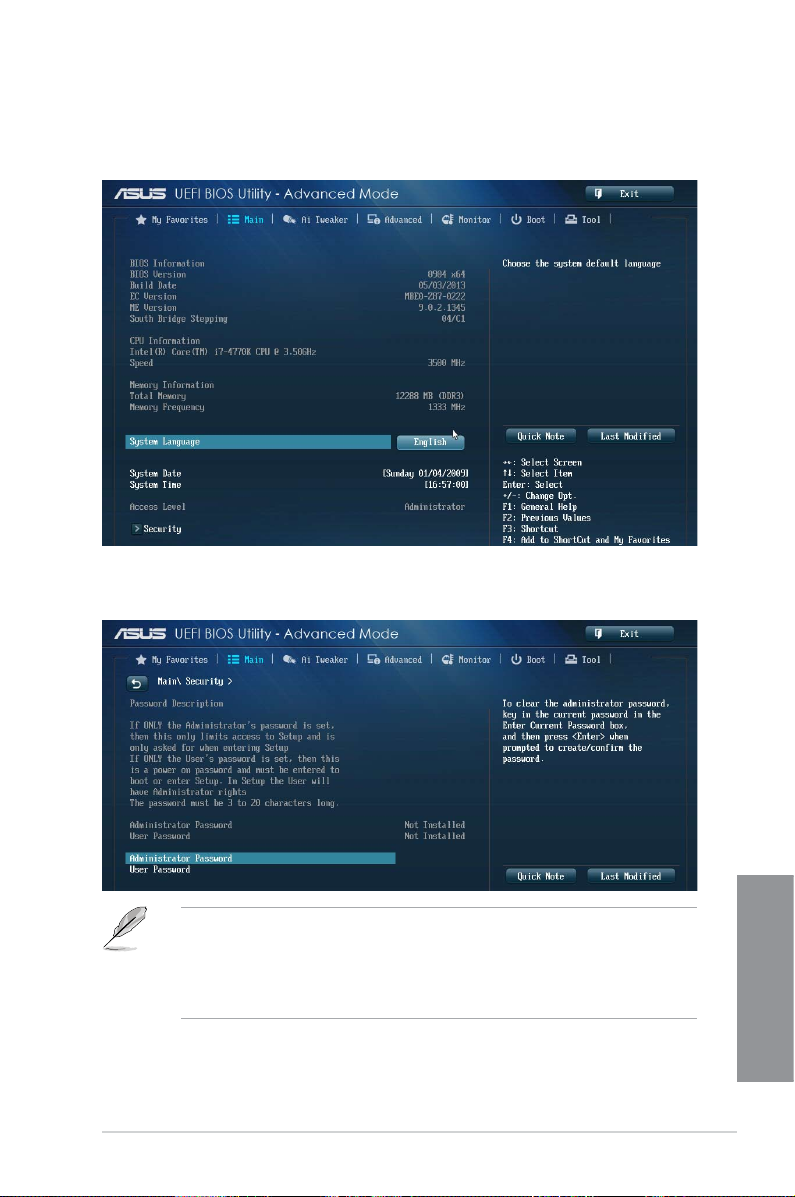
3.4 Main menu
The Main menu screen appears when you enter the Advanced Mode of the BIOS Setup
program. The Main menu provides you an overview of the basic system information, and
allows you to set the system date, time, language, and security settings.
Security
The Security menu items allow you to change the system security settings.
• If you have forgotten your BIOS password, erase the CMOS Real Time Clock (RTC)
• The Administrator or User Password items on top of the screen show the default
ASUS Z87-WS
RAM to clear the BIOS password. See section 1.2.6 Onboard buttons and switches
for information on how to erase the RTC RAM via the Clear CMOS button.
[Not
Installed]. After you set a password, these items show [Installed].
Chapter 3
3-7

Administrator Password
If you have set an administrator password, we recommend that you enter the administrator
password for accessing the system. Otherwise, you might be able to see or change only
selected elds in the BIOS setup program.
To set an administrator password:
1. Select the
2. From the
3. Conrm the password when prompted.
To change an administrator password:
1. Select the
2. From the
<Enter>.
3. From the
4. Conrm the password when prompted.
To clear the administrator password, follow the same steps as in changing an administrator
password, but press <Enter> when prompted to create/conrm the password. After you clear
the password, the Administrator Password item on top of the screen shows Not Installed.
Administrator Password item and press <Enter>.
Create New Password box, key in a password, then press <Enter>.
Administrator Password item and press <Enter>.
Enter Current Password box, key in the current password, then press
Create New Password box, key in a new password, then press <Enter>.
User Password
If you have set a user password, you must enter the user password for accessing the system.
The User Password item on top of the screen shows the default Not Installed. After you set a
password, this item shows Installed.
To set a user password:
1. Select the
2. From the
3. Conrm the password when prompted.
Chapter 3
3-8
User Password item and press <Enter>.
Create New Password box, key in a password, then press <Enter>.
Chapter 3: BIOS setup

To change a user password:
1. Select the
2. From the
<Enter>.
3. From the
4. Conrm the password when prompted.
To clear the user password, follow the same steps as in changing a user password, but press
<Enter> when prompted to create/conrm the password. After you clear the password, the
User Password item on top of the screen shows Not Installed.
User Password item and press <Enter>.
Enter Current Password box, key in the current password, then press
Create New Password box, key in a new password, then press <Enter>.
3.5 Ai Tweaker menu
The Ai Tweaker menu items allow you to congure overclocking-related items.
Be cautious when changing the settings of the Ai Tweaker menu items. Incorrect eld
values can cause the system to malfunction.
The conguration options for this section vary depending on the CPU and DIMM model you
installed on the motherboard.
Scroll down to display other BIOS items.
ASUS Z87-WS
Chapter 3
3-9

Ai Overclock Tuner [Auto]
Allows you to select the CPU overclocking options to achieve the desired CPU internal
frequency. Select any of these preset overclocking conguration options:
[Auto] Loads the optimal settings for the system.
[Manual] Allows you to automatically optimize the CPU ratio and BCLK frequency.
[X.M.P.] Allows your system to automatically optimize the CPU ratio, BCLK
Filter PLL [Auto]
Allows you to select a BCLK (base clock) mode when running in a high or low BCLK.
Conguration options: [Auto] [Low BCLK Mode] [High BCLK Mode]
BCLK Frequency [100.0]
Allows you to set the BCLK/PEG frequency to enhance the system performance. Use
the <+> or <-> keys to adjust the value. The values range from 80.0MHz to 300.0MHz.
eXtreme Memory Profile
Allows you to select the X.M.P. mode supported by your memory module.
Conguration options: [Prole #1] [Prole #2]
frequency, and memory parameters. If you install memory modules
supporting the eXtreme Memory Prole (X.M.P.) Technology, select this
item to set the proles supported by your memory modules for optimizing
the system performance.
The following item appears only when you set the Ai Overclocking Tuner to [Manual].
The following item appears only when you set the Ai Overclocking Tuner to [X.M.P.].
ASUS MultiCore Enhancement [Enabled]
[Enabled] Default set to [Enabled] for maximum performance under XMP/Manual/
[Disabled] Allows you to set to default core ratio settings.
User-dened memory frequency mode.
CPU Core Ratio [Auto]
Allows you to set the CPU ratio and synchronize automatically either per core or all cores.
Conguration options: [Auto] [Sync All Cores] [Per Core]
Chapter 3
3-10
When the CPU Core Ratio is set to [Per Core], the following item appears:
1-Core Ratio Limit [Auto]
Select [Auto] to apply the CPU default Turbo Ratio setting or manually
assign a 1-Core Limit value that must be higher than or equal to the 2-Core
Ratio Limit.
2-Core Ratio Limit [Auto]
Select [Auto] to apply the CPU default Turbo Ratio setting or manually
assign a 2-Core Limit value that must be higher than or equal to the 3-Core
Ratio Limit.
Chapter 3: BIOS setup

If you assign a value for 2-Core Ratio Limit, do not set the 1-Core Ratio Limit to [Auto].
3-Core Ratio Limit [Auto]
Select [Auto] to apply the CPU default Turbo Ratio setting or manually
assign a 3-Core Limit value that must be higher than or equal to the 4-Core
Ratio Limit.
If you assign a value for 3-Core Ratio Limit, do not set the 1-Core Ratio Limit and 2-Core
Ratio Limit to [Auto].
4-Core Ratio Limit [Auto]
Select [Auto] to apply the CPU default Turbo Ratio setting or manually
assign a 4-Core Limit value that must be higher than or equal to the 3-Core
Ratio Limit.
If you assign a value for 4-Core Ratio Limit, do not set the 1-Core Ratio Limit, 2-Core Ratio
Limit, and 3-Core Ratio to [Auto].
Min CPU Cache Ratio [Auto]
Allows you to set the minimum possible ratio on the Uncore part of the processor. Use the
<+> or <-> keys to adjust the value. The values depend on the CPU installed.
Max CPU Cache Ratio [Auto]
Allows you to set the maximum possible ratio on the Uncore part of the processor. Use the
<+> or <-> keys to adjust the value. The values depend on the CPU installed.
Internal PLL Overvoltage [Auto]
Allows you to enable the internal PLL Overvoltage for K-SKU CPUs to get the extreme
overclocking capability.
Conguration options: [Auto] [Enabled] [Disabled]
CPU bus speed : DRAM speed ratio mode [Auto]
Allows you to set the CPU bus speed to DRAM speed ratio mode.
[Auto] DRAM speed is set to the optimized settings.
[100:133] The CPU bus speed to DRAM speed ratio is set to 100:133.
[100:100] The CPU bus speed to DRAM speed ratio is set to 100:100.
Memory Frequency [Auto]
Allows you to set the memory operating frequency. The conguration options vary with the
BCLK/PCIE Frequency item settings.
CPU Graphics Max. Ratio [Auto]
[Auto] Allows you to automatically optimize the CPU Graphics Ratio depending on
the system loading.
[Manual] Allows you to set a value for an optimal CPU Grapics Ratio. Use the <+> or
<-> keys to adjust the CPU graphics ratio. The minimum value depends on
the installed CPU.
Chapter 3
ASUS Z87-WS
3-11

OC Tuner [As Is]
OC Tuner automatically overclocks the frequency and voltage of CPU and DRAM for
enhancing the system performance and accelerates the iGPU performance to the extreme
according to the integrated graphics loading.
Conguration options: [As Is] [Ratio First] [BCLK First]
EPU Power Saving Mode [Disabled]
Allows you to enable or disable the EPU power saving function.
Conguration options: [Disabled] [Enabled]
DRAM Timing Control
The subitems in this menu allow you to set the DRAM timing control features. Use the <+> or
<-> keys to adjust the value. To restore the default setting, type [auto] using the keyboard and
press the <Enter> key.
Changing the values in this menu may cause the system to become unstable! If this
happens, revert to the default settings.
Primary Timings
DRAM CAS# Latency [Auto]
Conguration options: [Auto] [1] – [31]
DRAM RAS# to CAS# Delay [Auto]
Conguration options: [Auto] [1] – [31]
DRAM RAS# PRE Time [Auto]
Conguration options: [Auto] [1] – [31]
DRAM RAS# ACT Time [Auto]
Conguration options: [Auto] [1] – [63]
DRAM COMMAND Mode [Auto]
Conguration options: [Auto] [1] – [3]
Secondary Timings
DRAM RAS# to RAS# Delay [Auto]
Conguration options: [Auto] [1] – [15]
DRAM REF Cycle Time [Auto]
Chapter 3
3-12
Conguration options: [Auto] [1] – [511]
DRAM Refresh Interval [Auto]
Conguration options: [Auto] [1] – [65535]
DRAM WRITE Recovery Time [Auto]
Conguration options: [Auto] [1] – [16]
DRAM READ to PRE Time [Auto]
Conguration options: [Auto] [1] – [15]
Chapter 3: BIOS setup

DRAM FOUR ACT WIN Time [Auto]
Conguration options: [Auto] [1] – [255]
DRAM WRITE to READ Delay [Auto]
Conguration options: [Auto] [1] – [15]
DRAM CKE Minimum pulse width [Auto]
Conguration options: [Auto] [1] – [15]
DRAM CAS# Write Latency [Auto]
Conguration options: [Auto] [1] – [31]
RTL IOL control
DRAM RTL (CHA_R0D0) [Auto]
Conguration options: [Auto] [1] - [63]
DRAM RTL (CHA_R0D1) [Auto]
Conguration options: [Auto] [1] - [63]
DRAM RTL (CHA_R1D0) [Auto]
Conguration options: [Auto] [1] - [63]
DRAM RTL (CHA_R1D1) [Auto]
Conguration options: [Auto] [1] - [63]
DRAM RTL (CHB_R0D0) [Auto]
Conguration options: [Auto] [1] - [63]
DRAM RTL (CHB_R0D1) [Auto]
Conguration options: [Auto] [1] - [63]
DRAM RTL (CHB_R1D0) [Auto]
Conguration options: [Auto] [1] - [63]
DRAM RTL (CHB_R1D1) [Auto]
Conguration options: [Auto] [1] - [63]
DRAM IO-L (CHA_R0D0) [Auto]
Conguration options: [Auto] [1] - [15]
DRAM IO-L (CHA_R0D1) [Auto]
Conguration options: [Auto] [1] - [15]
DRAM IO-L (CHA_R1D0 [Auto]
Conguration options: [Auto] [1] - [15]
DRAM IO-L (CHA_R1D1 [Auto]
Conguration options: [Auto] [1] - [15]
DRAM IO-L (CHB_R0D0 [Auto]
Conguration options: [Auto] [1] - [15]
Chapter 3
ASUS Z87-WS
3-13

DRAM IO-L (CHB_R0D1) [Auto]
Conguration options: [Auto] [1] - [15]
DRAM IO-L (CHB_R1D0 [Auto]
Conguration options: [Auto] [1] - [15]
DRAM IO-L (CHB_R1D1 [Auto]
Conguration options: [Auto] [1] - [15]
Third Timings
tRDRD [Auto]
Conguration options: [Auto] [1] – [7]
tRDRD_dr [Auto]
Conguration options: [Auto] [1] – [15]
tRDRD_dd [Auto]
Conguration options: [Auto] [1] – [15]
tWRRD [Auto]
Conguration options: [Auto] [1] – [63]
tWRRD_dr [Auto]
Conguration options: [Auto] [1] – [15]
tWRRD_dd [Auto]
Conguration options: [Auto] [1] – [15]
tWRWR [Auto]
Conguration options: [Auto] [1] – [7]
tWRWR_dr [Auto]
Conguration options: [Auto] [1] – [15]
tWRWR_dd [Auto]
Conguration options: [Auto] [1] – [15]
Dec_WRD
Conguration options: [Auto] [0] – [1]
tRDWR [Auto]
Conguration options: [Auto] [1] – [31]
tRDWR_dr [Auto]
Chapter 3
Conguration options: [Auto] [1] – [31]
tRDWR_dd [Auto]
Conguration options: [Auto] [1] – [31]
3-14
Chapter 3: BIOS setup

MISC
MRC Fast Boot [Auto]
Allows you to enable, disable or automatically set the MRC fast boot.
Conguration options: [Auto] [Enable] [Disable]
DRAM CLK Period [Auto]
Conguration options: [Auto] [1] – [14]
Channel A/B DIMM Control [Enable Bot...]
Conguration options: [Enable Both DIMMS] [Disable DIMM0] [Disable DIMM1]
[Disable Both DIMMS]
Scrambler Setting [Optimized ...]
Allows you to set the optimized scrambler setting for stability.
Conguration options: [Optimized (ASUS] [Default (MRC)]
DIGI+ Power Control
CPU Load-Line Calibration [Auto]
Load-line is dened by Intel® VRM specication and affects CPU power voltage. The
CPU working voltage will decrease proportionally to CPU loading. Higher load-line
calibration could get higher voltage and good overclocking performance, but increases
the CPU and VRM thermal conditions.
Select from Level 1 to Level 8 to adjust CPU power voltage from 0% to 100%.
The actual performance boost may vary depending on your CPU specication.
DO NOT remove the thermal module. The thermal conditions should be monitored.
CPU Voltage Frequency [Auto]
Frequency switching affects the VRM transient response and the thermal component
conditions. Higher frequency gets quicker transient response.
Conguration options: [Auto] [Manual]
DO NOT remove the thermal module when setting this item to [Manual Mode]. The thermal
conditions should be monitored.
The following item appears only when you set the CPU Voltage Frequency to [Manual].
CPU Fixed Frequency [300]
This item allows you to set a xed CPU Voltage frequency. Use the <+> or
<-> keys to adjust the value. The values range from 300kHz to 500kHz with
a 50kHz interval.
ASUS Z87-WS
Chapter 3
3-15

The following items appear only when you set the CPU Voltage Frequency to [Auto].
VRM Spread Spectrum [Disabled]
Enable the VRM Spread Spectrum to enhance system stability.
Conguration options: [Disabled] [Enabled]
Active Frequency Mode [Disabled]
Enable the Active Frequency Mode for an enhanced power saving
condition.
Conguration options: [Disabled] [Enabled]
CPU Power Phase Control [Auto]
Allows you to set the power phase control of the CPU.
Conguration options: [Auto] [Standard] [Optimized] [Extreme] [Manual Adjustment]
DO NOT remove the thermal module when setting this item to [Extreme] and [Manual
Adjustment]. The thermal conditions should be monitored.
The following item appears only when you set the CPU Power Phase Control to [Manual
Adjustment].
Manual Adjustment [Fast]
Allows you to set a faster phase response for the CPU to increase system
performance or to slower phase response to decrease DRAM power
efciency.
Conguration options: [Ultra Fast] [Fast] [Medium] [Regular]
CPU Power Duty Control [T.Probe]
DIGI + VRM Duty Control adjusts the current of every VRM phase and the thermal
conditions of every phase component.
[T. Probe] Select to maintain the VRM thermal balance.
[Extreme] Select to maintain the current VRM balance.
CPU Current Capability [Auto]
DIGI+ VRM CPU Current Capability provides wider total power range for overclocking.
A higher value setting gets higher VRM power consumption delivery and extends the
overclocking frequency range simultaneously.
Chapter 3
3-16
Conguration options: [Auto] [100%] [110%] [120%] [130%] [140%]
DO NOT remove the thermal module. The thermal conditions should be monitored.
Choose a higher value when overclocking, or under a high CPU loading for extra power
support.
Chapter 3: BIOS setup

CPU Power Thermal Control [130]
A higher temperature brings a wider CPU power thermal range and extends the
overclocking tolerance to enlarge the O.C. potential. Use the <+> or <-> keys to adjust
the value. The values depend on the CPU installed.
DO NOT remove the thermal module. The thermal conditions should be monitored.
DRAM Current Capability [100%]
A higher value brings a wider total power range, and extends the overclocking range
simultaneously.
Conguration options: [100%] [110%] [120%] [130%]
DRAM Voltage Frequency [Auto]
Allows you to adjust the DRAM switching frequency. Assign a xed high DRAM
frequency to increase the O.C. range, or a low DRAM frequency for a better system
stability.
Conguration options: [Auto] [Manual]
The following item appears only when you set set the DRAM Frequency Mode item to
[Manual].
DRAM Fixed Frequency Mode [300]
Allows you to set a xed DRAM frequency to increase the overclocking
range or a low DRAM frequency for better system stability. Use the <+> or
<-> keys to adjust the value. The values range from 300kHz to 500kHz with
a 50kHz interval.
DRAM Power Phase Control [Auto]
[Auto] Allows you to set the Auto mode.
[Optimized] Allows you to set the ASUS optimized phase tuning prole.
[Extreme] Allows you to set the full phase mode.
CPU Power Management
The subitems in this menu allow you to set the CPU ratio and their features.
Enhanced Intel SpeedStep Technology [Enabled]
Allows the operating system to dynamically adjust the processor voltage and cores
frequency, resulting to a decreased average power consumption and decreased
average heat production.
Conguration options: [Disabled] [Enabled]
Turbo Mode [Enabled]
Allows you to enable your core processor’s speed to run faster than the base operating
frequency when it is below operating power, current and temperature specication limit.
Conguration options: [Disabled] [Enabled]
The following items appear only when you set the Turbo Mode to [Enabled].
ASUS Z87-WS
Chapter 3
3-17

Turbo Mode Parameters
Long Duration Package Power Limit [Auto]
Allows you to limit the Turbo Ratio’s time duration that exceeds the TDP
(Thermal Design Power) for maximum performance. Use the <+> or <->
keys to adjust the value. The values range from 1W t0 4096W.
Package Power Time Window [Auto]
Also known as Power Limit 1, and allows you to maintain the time window
for Turbo Ratio over TDP (Thermal Design Power). Use the <+> or <->
keys to adjust the value. The values range from 1 to 127 in seconds.
Short Duration Package Power Limit [Auto]
Also known as Power Limit 2, and allows you to provide rapid protection
when the package power exceeds the Power Limit 1. Use the <+> or <->
keys to adjust the value. The values range from 1W t0 4096W.
CPU Integrated VR Current Limit [Auto]
Allows you to set a higher current limit to prevent frequency and power
throttling when overclocking. Use the <+> or <-> keys to adjust the value.
The values range from 0.125 to 1023.875 with a 0.125 interval.
CPU Internal Power Switching Frequency
Frequency Tuning Mode [Auto]
Allows you to increase or decrease the switching frequency of the internal regulator.
Decrease to help consume less power or increase to help votlage stability. When this
item is set to [+] or [-], the Frequency Tuning Offset appears and allows you to set its
value from 0% to 6%.
CPU Internal Power Fault Control
Thermal Feedback [Auto]
Allows your system to take precautionary actions to be taken by the CPU when the
thermal conditions of the external regulator exceeds the threshold.
Conguration options: [Auto] [Disabled] [Enabled]
CPU Integrated VR Fault Management [Auto]
Disable this item to prevent tripping the Fully Integrated Voltage Regulator when doing
over-voltage. We recommend you to disable this item when overclocking.
Conguration options: [Auto] [High Performance] [Balanced]
Chapter 3
3-18
CPU Internal Power Configuration
CPU Integrated VR Efficiency Management [Auto]
Allows you to improve power saving when the processor is in low power state. Disable
to make the Fully Integrated Voltage Regulator work in high performance at all times.
Conguration options: [Auto] [High Performance] [Balanced]
Chapter 3: BIOS setup

Power Decay Mode [Auto]
Allows your system to improve the power saving mode on the Fully Integrated Voltage
Regulator as the processor goes into low current state.
Conguration options: [Auto] [Disabled] [Enabled]
Idle Power-in Response [Auto]
Allows you to set the slew rate for the Fully Integrated Voltage Regulator as it enters
manual override mode.
Conguration options: [Auto] [Regular] [Fast]
Idle Power-out Response [Auto]
Allows you to set the slew rate for the Fully Integrated Voltage Regulator as it exits
manual override mode.
Conguration options: [Auto] [Regular] [Fast]
Power Current Slope [Auto]
Allows you to set the gradient of the high-speed active phase current balance during
load transients to eliminate current imbalance that can result from a load current
oscillating near the switching frequency.
Conguration options: [Auto] [LEVEL -4] - [LEVEL 4]
Power Current Offset [Auto]
Allows you to increase or decrease the output current sensed by the CPU. It nds the
balance between optimal regulating while staying below the current threshold.
Conguration options: [Auto] [100%] [87.5%] [75.0%] [62.5%] [50.0%] [37.5%] [25.0%]
[12.5%] [0%] [-12.5%] [-25.0%] [-37.5%] [-50.0%] [-62.5%] [-75.0%] [-87.5%] [-100%]
Power Fast Ramp Response [Auto]
Allows you to increase to enhance the response of the voltage regulator during the
load transient.
Conguration options: [Auto] [0.00] - [1.50]
CPU Internal Power Saving Control
Power Saving Level 1 Threshold [Auto]
Lower value provides sufcient overclocking tolerance to enlarge the overclocking
potential. Higher value provides better power-saving condition.Use <+> or <-> key to
adjust the value. The values range from 0A to 80A at 1Amp increment.
Power Saving Level 2 Threshold [Auto]
Lower value provides sufcient overclocking tolerance to enlarge the overclocking
potential. Higher value provides better power-saving condition.Use <+> or <-> key to
adjust the value. The values range from 0A to 50A at 1Amp increment.
Power Saving Level 3 Threshold [Auto]
Lower value provides sufcient overclocking tolerance to enlarge the overclocking
potential. Higher value provides better power-saving condition.Use <+> or <-> key to
adjust the value. The values range from 0A to 30A at 1Amp increment.
ASUS Z87-WS
Chapter 3
3-19

Extreme OV [Disabled]
Default set to DIsabled and help to protect CPU not been burned by Over Voltage. When set
to Enabled, you might choose high level voltage to overclock, but not guaranteed CPU life.
Conguration options: [Disabled] [Enabled]
CPU Core Voltage [Auto]
Allows you to congure the amount of voltage fed to the cores of the processor. Increase the
amount of voltage when increasing core frequency.
Conguration options: [Auto] [Manual Mode] [Offset Mode] [Adaptive Mode]
The following item appears only when you set the CPU Core Voltage to [Manual].
CPU Core Voltage Override [Auto]
Allows you to set the CPU Core Voltage override. Use the <+> or <-> keys to adjust the
value, The values range from 0.001V to 1.920V with a 0.001V interval.
The following items appear only when you set the CPU Core Voltage to [Offset Mode] or
[Adaptive Mode].
Offset Mode Sign [+]
[+] To offset the voltage by a positive value.
[–] To offset the voltage by a negative value.
CPU Core Voltage Offset
Use the <+> or <-> keys to adjust the value. The values range from 0.001V
to 0.999V with a 0.001V interval.
The following item appears only when you set the CPU Core Voltage to [Adaptive Mode].
CPU Cache Voltage [Auto]
Allows you to congure the amount of voltage fed to the uncore of the processor including its
cache. Increase the voltage when increasing Ring frequency.
Chapter 3
Conguration options: [Auto] [Manual Mode] [Offset Mode]
CPU Cache Voltage Override [Auto]
Allows you to set the CPU Cache Voltage override. Use the <+> or <-> keys to adjust
the value, The values range from 0.001V to 1.920V with a 0.001V interval.
3-20
Additional Turbo Mode CPU Core Voltage [Auto]
Allows you to add voltage for Turbo Mode CPU core. Use the <+> or <->
keys to adjust the value. The values range from 0.001V to 1.920V with a
0.001V interval.
The following item appears only when you set the CPU Cache Voltage to [Manual Mode].
The following items appear only when you set the CPU Core Voltage to [Offset Mode].
Chapter 3: BIOS setup

Offset Mode Sign [+]
[+] To offset the voltage by a positive value.
[–] To offset the voltage by a negative value.
CPU Cache Voltage Offset
Allows you to set the CPU cache voltage offset. Use the <+> or <-> keys to adjust the
value. The values range from 0.001V to 0.999V with a 0.001V interval.
CPU Graphics Voltage [Auto]
Allows you to congure the amount of voltage fed to the onboard graphics unit on the
processor. Increase the amount of voltage when increasing iGPU frequency.
Conguration options: [Auto] [Manual Mode] [Offset Mode] [Adaptive Mode]
The following item appears only when you set the CPU Core Voltage to [Manual].
CPU Graphics Voltage Override [Auto]
Allows you to set the CPU Graphics Voltage override. Use the <+> or <-> keys to
adjust the value, The values range from 0.001V to 1.920V with a 0.001V interval.
The following items appear only when you set the CPU Core Voltage to [Offset Mode] or
[Adaptive Mode].
Offset Mode Sign [+]
[+] To offset the voltage by a positive value.
[–] To offset the voltage by a negative value.
CPU Graphics Voltage Offset
Use the <+> or <-> keys to adjust the value. The values range from 0.001V
to 0.999V with a 0.001V interval.
The following item appears only when you set the CPU Core Voltage to [Adaptive Mode].
Additional Turbo Mode CPU Graphics Voltage [Auto]
This item allows you to add voltage for Turbo Mode CPU Graphics. Use
the <+> or <-> keys to adjust the value. The values range from 0.001V to
1.920V with a 0.001V interval.
CPU System Agent Voltage Offset Mode Sign [+]
[+] To offset the voltage by a positive value.
[–] To offset the voltage by a negative value.
CPU System Agent Voltage Offset [Auto]
Allows you to congure the amount of voltage fed to the system agent of the processor
including its PCIe controller and power control unit. Increase the amount of voltage
when increasing DRAM frequency. Use the <+> or <-> keys to adjust the value. The
values range from 0.001V to 0.999V with a 0.001V interval.
ASUS Z87-WS
Chapter 3
3-21

CPU Analog I/O Voltage Offset Mode Sign [+]
[+] To offset the voltage by a positive value.
[–] To offset the voltage by a negative value.
CPU Analog I/O Voltage Offset [Auto]
Allows you to congure the amount of voltage fed to the analog portion of the I/O on
the processor. Increase the amount of voltage when increasing DRAM frequency. Use
the <+> or <-> keys to adjust the value. The values range from 0.001V to 0.999V with
a 0.001V interval.
CPU Digital I/O Voltage Offset Mode Sign [+]
[+] To offset the voltage by a positive value.
[–] To offset the voltage by a negative value.
CPU Digital I/O Voltage Offset [Auto]
Allows you to congure the amount of voltage fed to the digital portion of the I/O on the
processor. Increase the amount of voltage when increasing DRAM frequency. Use the
<+> or <-> keys to adjust the value. The values range from 0.001V to 0.999V with a
0.001V interval.
SVID Support [Auto]
When overclocking, set this item to [Enabled]. Disabling this item would stop the processor
from communicating with the external voltage regulator.
Conguration options: [Auto] [Disabled] [Enabled]
SVID Voltage Override [Auto]
Allows you to set the SVID Voltage override. By default, this item takes the standard
value of the installed CPU. You can use the <+> or <-> keys to adjust the value. The
values range from 0.001V to 2.440V with a 0.001V interval.
CPU Input Voltage [Auto]
Allows you to set an input voltage for the processor by the external voltage regulator. By
default, this item takes the standard value of the installed CPU. You can use the <+> or <->
keys to adjust the value. The values range from 0.800V to 3.040V with a 0.010V interval.
DRAM Voltage [Auto]
Allows you to set the DRAM voltage. You can use the <+> or <-> keys to adjust the value.
Chapter 3
The values range from 1.20V to 1.92V with a 0.005V interval.
The following item appears only when you set SVID Support to [Enabled].
According to Intel® CPU specications, DIMMs with voltage requirement over 1.65V may
damage the CPU permanently. We recommend that you install the DIMMs with the voltage
requirement below 1.65V.
PCH VLX Voltage [Auto]
Allows you to set the voltage for the I/O on the PCH. Use the <+> or <-> keys to adjust the
value. The values range from 1.2000V to 2.0000V with a 0.0125V interval.
3-22
Chapter 3: BIOS setup

PCH Voltage [Auto]
Allows you to set the Core voltage for the PCH (Platform Controller Hub). You can use the
<+> or <-> keys to adjust the value. The values range from 0.70V to 1.50V with a 0.0125V
interval.
• The values of the CPU PLL Voltage, CPU Manual Voltage, CPU Offset Voltage,
iGPU Manual Voltage, iGPU Offset Voltage, DRAM Voltage, VCCSA Voltage, VCCIO
Voltage, and PCH Voltage items are labeled in different color, indicating the risk levels
of high voltage settings.
• The system may need better cooling system for a more stable performance under high
voltage settings.
VTTDDR Voltage [Auto]
Allows you to set the termination voltage for the system memory. You can use the <+> or <->
keys to adjust the value. The values range from 0.6000V to 1.0000V with a 0.0125V interval.
DRAM CTRL REF Voltage [Auto]
This item is the DRAM reference voltage for the control lines from the memory bus. You can
use the <+> or <-> keys to adjust the value. The values range from 0.3950x to 0.6300x with a
0.0050x interval.
DRAM DATA REF Voltage on CHA/CHB [Auto]
This item is the DRAM reference voltage for the data lines on Channels A and B. You can
use the <+> or <-> keys to adjust the value. The values range from 0.395x to 0.630x with a
0.005x interval.
Clock Crossing VBoot [Auto]
Allows you to increase the value of the clock crossing voltage boot when the rising edge of
the BCLK DN is equal to the falling edge of the BCLK DP. You can use the <+> or <-> keys to
adjust the value. The values range from 0.1V to 1.9V with a 0.00625V interval.
Clock Crossing Reset Voltage [Auto]
Allows you to increase the value of the clock crossing reset voltage when the rising edge of
the BCLK DN is equal to the falling edge of the BCLK DP. You can use the <+> or <-> keys to
adjust the value. The values range from 0.1V to 1.9V with a 0.10625V interval.
Clock Crossing Voltage [Auto]
Allows you to increase the value of the clock crossing voltage when the rising edge of the
BCLK DN is equal to the falling edge of the BCLK DP. You can use the <+> or <-> keys to
adjust the value. The values range from 0.1V to 1.9V with a 0.10625V interval.
CPU Spread Spectrum [Auto]
[Auto] Automatic conguration.
[Disabled] Enhances the BCLK overclocking ability.
[Enabled] Sets to [Enabled] for EMI control.
Chapter 3
ASUS Z87-WS
3-23

3.6 Advanced menu
The Advanced menu items allow you to change the settings for the CPU and other system
devices.
Be cautious when changing the settings of the Advanced menu items. Incorrect eld values
can cause the system to malfunction.
Chapter 3
3-24
Chapter 3: BIOS setup

3.6.1 CPU Conguration
The items in this menu show the CPU-related information that the BIOS automatically
detects.
The items in this menu may vary based on the CPU installed.
Intel Adaptive Thermal Monitor [Enabled]
[Enabled] Enables the overheated CPU to throttle its clock speed to cool down.
[Disabled] Disables the CPU thermal monitor function.
Hyper-threading [Enabled]
The Intel Hyper-Threading Technology allows a hyper-threading processor to appear as two
logical processors to the operating system, allowing the operating system to schedule two
threads or processes simultaneously.
[Enabled] Two threads per activated core are enabled.
[Disabled] Only one thread per activated core is enabled.
This Item apears only if you installed a CPU that supports the Intel Hyper-threading
technology.
Active Processor Cores [All]
Allows you to choose the number of CPU cores to activate in each processor package.
Conguration options: [All] [1] [2] [3]
ASUS Z87-WS
Chapter 3
3-25

Limit CPUID Maximum [Disabled]
[Enabled] Allows legacy operating systems to boot even without support for CPUs
[Disabled] Disables this function.
Execute Disable Bit [Enabled]
[Enabled] Enables the No-Execution Page Protection Technology.
[Disabled] Forces the XD feature ag to always return to zero (0).
Intel Virtualization Technology [Disabled]
[Enabled] Allows a hardware platform to run multiple operating systems separately
[Disabled] Disables this function.
Hardware Prefetcher [Enabled]
[Enabled] Allows a hardware platform to automatically analyze the requirements and
[Disabled] Disables this function.
Adjacent Cache Line Prefetch [Enabled]
[Enabled] Allows a hardware platform to perform adjacent cache line prefetching.
[Disabled] Disables this function.
Boot performance mode [Max Non-Turbo Performance]
Allows you to select the boot performance before entering the OS.
Conguration options: [Max Non-Turbo Performance] [Max Battery] [Turbo Performance]
Dynamic Storage Accelerator [Disabled]
Allows you to enable or disable Dynamic Storage Accelerator for C state conguration.
Conguration options: [Enabled] [Disabled]
CPU Power Management Conguration
This item allows you to manage and congure the CPU’s power.
Enhanced Intel SpeedStep Technology [Enabled]
Allows your system to adjust the processor’s voltage and cores frequency, resulting in
decreased power consumption and heat production.
Chapter 3
[Disabled] The CPU runs at its default speed.
[Enabled] The system controls the CPU speed.
with extended CPUID functions.
and simultaneously, enabling one system to virtually function as several
systems.
prefetch data and codes for the CPU.
3-26
Chapter 3: BIOS setup
 Loading...