

Page 1

Owner's Operating
Service Instruction
Manual
• ASSEMBLY
lOtfc
Model Nos
136-480A
•OPERATION
• REPAIR PARTS
136-485A
MTD PRODUCTS INC
PRINTED IN U.S.A.
• 5389 tlEST 130th STREET •
P. 0. BOX 2741 CLEVELAND OHIO 44111
FORM NO. 770-6037
Page 2

IMPORTANT
It is suggested that this manual be read in its entirety before attempting to assemble or operate. Keep this
manual in a safe place for future reference and for ordering replacement parts.
This unit is shipped WITHOUT GASOLINE or OIL. After assembly, see operating section of this manuai for
proper fuel and amount.
SAFE OPERATION PRACTICES FOR RIDING VEHICLES
1. Know the controls and how to stop quickly—
READ THE OWNER’S MANUAL.
2. Do not allow children to operate vehicle. Do
not allow adults to operate it without proper
instruction.
3. Do not carry passengers. Keep children and
pets a safe distance away.
4. Clear work area of objects which might be
picked up and thrown.
5. Disengage all attachment clutches and shift
into neutral before attempting to start engine.
6. Disengage power to attachment(s) and stop
engine before leaving operator position.
7. Disengage power to attachment(s) and stop
engine before making any repairs or adjust
ments.
8. Disengage power to attachment(s) when
transporting or not in use.
9. Take all possible precautions when leaving
vehicle unattended such as disengaging
power-take-off, lowering attachments, shift
ing into neutral, setting parking brake,
stopping engine and removing key.
10. Do not stop or start suddenly when going
uphill or downhill. Mow up and down face of
steep slopes; never across the face.
11. Reduce speed on slopes and in sharp turns to
prevent tipping or loss of control. Exercise ex
treme caution when changing direction on
slopes.
12. Stay alert for holes in terrain and other hidden
hazards.
13. Use care when pulling loads or using heavy
equipment.
A. Use only approved drawbar hitch points.
B. Limit loads to those you can safely
control.
C. Do not turn sharply. Use care when
backing.
D. Use counterweight(s) or wheel weights
when suggested in owner’s manual.
14. Watch out for traffic when crossing or near
roadways.
15. When using any attachments never direct dis
charge of material toward bystanders nor
allow anyone near vehicle while in operation.
16. Handle gasoline with care—it is highly
flammable.
A. Use approved gasoline container.
B. Never remove cap or add gasoline to a run
ning or hot engine or fill fuel tank indoors.
Wipe up spilled gasoline.
C. Open doors if engine is run in garage—ex
haust fumes are dangerous. Do not run
engine indoors.
17. Keep the vehicle and attachments in good
operating condition, and keep safety devices
in place. Use guards as instructed in owner’s
manual.
18. Keep all nuts, bolts, and screws tight to be
sure the equipment is in safe working
condition.
19. Never store the equipment with gasoline in
the tank inside a building where fumes may
reach an open flame or spark. Allow engine to
cool before storing in any enclosure.
20. To reduce fire hazard keep engine free of
grass, leaves or excessive grease.
21. The vehicle and attachments should be
stopped and inspected for damage after
striking a foreign object, and the damage
should be repaired before restarting and
operating the equipment.
22. Do not change the engine governor settings or
overspeed the engine.
23. When using the vehicle with mower, proceed
as follows:
(1) Mow only in daylight or in good artificial
light.
(2) Never make a cutting height adjustment
while engine is running if operator must
dismount to do so.
(3) Shut engine off when removing grass
catcher and/or unclogging chute.
(4) Check blade mounting bolts for proper
tightness at frequent intervals.
24. Check grass catcher bags frequently for wear
or deterioration. Replace with new bags for
safety protection.
25. Look behind to make sure the area is clear
before placing the transmission in reverse and
backing up.
Page 3
INDEX
Safe Operation Practices.....
Index......................................................................... 3
Assembly and Battery Instructions
Controis.....................................................................6
Operating Instructions.............................................9
Maintenance
Lubrication............................................................. 10
Adjustments...........................................................11
Belt Replacement
Off-Season Storage................................................15
Trouble Shooting Chart for Recoil Start
Trouble Shooting Chart for Electric Start
Schematic for Recoil Start Unit.............................19
Schematic for Electric Start Unit
GRASS CATCHER Model No. 196-015A is
available as optional equipment for the mowers
shown in this manual.
...........................................................
...................................................
...................................
.....................
..............
............
..........................
2
4
10
13
16
17
20
\ warning )
The mower should not be operated
without the entire grass catcher or
chute deflector in place.
NOTE
Under normal usage bag material is
subject to wear, and should be
checked periodically. Be sure any
replacement bag complies with the
mower manufacturer’s recommen
dations.
For replacement bags, use only fac
tory authorized replacement bag No.
764-0121.
Differential Breakdown and Parts List
Deck Linkage
Transmission Breakdown......................................23
Transmission Parts List.........................................24
Wheel Chart.
Illustrated Parts for R.H. Side of Rider
Parts List for R.H. Side of Rider
Illustrated Parts for L.H. Side of Rider
Parts List for L.H. Side of Rider............................29
Illustrated Parts for Frame View
Parts List for Frame View
Illustrated Parts for Deck View
Parts List for Deck View
Parts Information....................................Back Cover
TIRE PRESSURE
FOR SHIPPING PURPOSES, THE TIRES ON
YOUR UNIT MAY BE OVER-INFLATED. TIRE
PRESSURE SHOULD BE REDUCED BEFORE
UNIT IS PUT INTO OPERATION. PRESSURE
SHOULD BE APPROXIMATELY 15 P.S.I. EQUAL
TIRE PRESSURE SHOULD BE MAINTAINED ON
ALL TIRES. MAXIMUM TIRE PRESSURE IS 30
P.S.I.
Reference to right-hand or left-hand
side of machine is from the driver’s
seat facing forward.
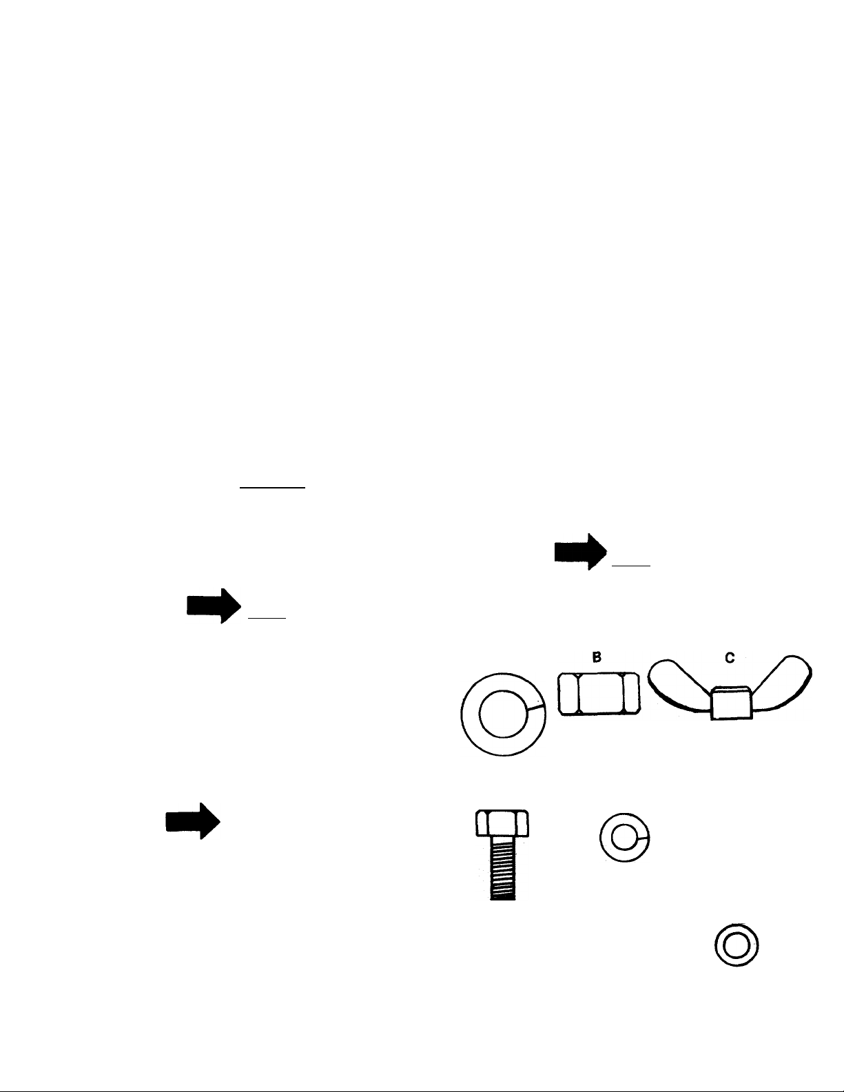
Lockwasher 1/2”
..........................................................
........................................................
...........
.............................
........................................
NOTE
Hex Nut
1/2—13
................
.25
................
..........
..................27
.................
...........................
...........................31
Wing Nut 1/4—20
21
22
26
28
30
32
33
IMPORTANT
After striking a foreign object, stop
the engine. Remove wire from spark
plug, thoroughly inspect the mower
for any damage, and repair the dam
age before restarting and operating
the mower.
The steering wheel and seat, with the necessary
hardware, are easily assembled to the machine.
On the electric starter models, the battery must be
activated and installed as outlined in this section.
D
Lock Washer 1 /4”
Hex Bolt
1/4—20x5/8
(ED
Hex Lock Nut
3/8—16 Belleville Washer 3/8”
FIGURE 1. HARDWARE SUPPLIED
¿D
Hex Nut
1/4—20
H
Page 4
ASSEMBLY
Step 1. Remove the lawn mower and all parts
from the carton. Make certain that all
loose parts and literature have been
removed before the carton is discarded.
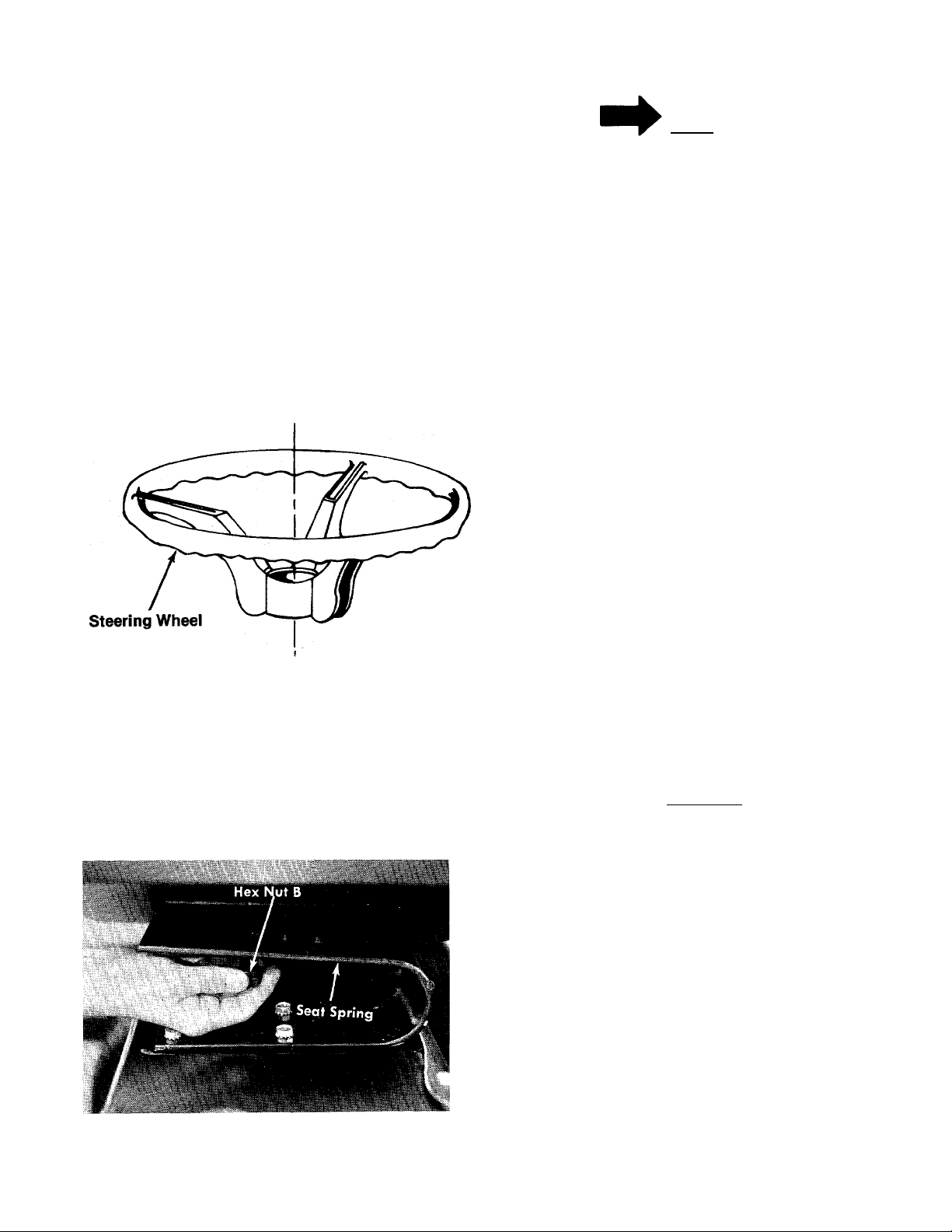
Step 2. Place steering wheel over steering shaft.
Step 3. Secure with Believille washer and hex
nut. See figure 2.
Step 4. Press the cap on the steering wheei by
hand. See figure 2.
Steering Wheel Cap—
NOTE
Check ALL nuts and bolts for cor
rect tightness.
BATTERY INFORMATION
FOR ELECTRIC START
MODELS
Hex Nut-
Belleville Washer ’
FIGURE 2. STEERING WHEEL ASSEMBLY
mounting bolt molded in the seat.
A. Select one of three hole locations on
seat spring.
B. Place seat on spring and secure with
lockwasher (A) and hex nut (B). See
figures 1 and3.
■G
■H
\ WARNING (
Battery acid must be handled with great care
A.
as it will blister the skin and damage clothing.
It is advisable to wear goggles, rubber gloves,
and a protective apron when working with it.
B.
Neutralize acid spilled on clothing with dilute
ammonia water or a water solution of baking
soda. If acid gets on clothes, dilute it with
clean water first, then neutralize.
C. If for any reason acid should be spattered in
the eyes, wash it out immediately with clean
cold water. Seek medical aid if discomfort
continues.
D. Since battery acid is corrosive to metals, do
not pour into any sink or drain. Rinse empty
theStep 5. Your molded seat comes with
electrolyte containers and mutilate before
discarding.
I DANGER \
BATTE-RIES CONTAIN SULFURIC
ACID AND MAY CONTAIN EXPLO
SIVE GASES (when electrolyte has
been added)
FIGURE 3. SEAT ASSEMBLY
A. Keep sparks, flame, cigarettes away.
B. Hydrogen gas is generated during charging
and discharging.
C. Ventilate when charging or using in enclosed
space.
D. When using a charger—to avoid sparks,
NEVER connect or disconnect charger clips to
battery while charger is turned on.
E. Always shield eyes, protect skin and clothing
when working near batteries.
Page 5

ACTIVATING THE
BATTERY
1. Place battery to be filled on bench or
workbench. NEVER activate battery in unit.
Remove vent caps from all cells.
2. Fill each cell carefully using battery grade
1.250-1.265 specific gravity. Sulfuric acid to
be 3/8” above the top of the separators or to
split ring.
3-. Allow battery to set for 20 minutes to I/2 hour.
Add additional acid if necessary to bring it up
to the proper levei.
4. Repiace the vent caps.
5. The battery can now be charged after the 20
minutes setting period. Battery can be SLOW
CHARGED (DO NOT FAST CHARGE) at a
maximum bench rate of 4-5 amperes until the
specific gravity reading is 1.265-1.275. A
charging rate in excess of this will buckle and
warp the positive plates and perforate the
separators. If electrolyte bubbles violently
while charging, reduce charging rate until
excessive bubbling action subsides, then
continue charging until specific gravity is
reached.
CAUTION
A
After battery has been in service,
add only approved water. DO NOT
ADD ACID.
B. TO INSTALL BATTERY
To install the battery in this unit, refer to next
column.
C. MAINTENANCE
1. Check periodically (every two weeks or
before and after charging) to be sure elec
trolyte level is 9/16” above separator
plates. Add only distilled water or good
quality drinking water. NEVER add addi
tional acid or other chemicals to battery
after initial activation.
2. The battery should be checked with a
hydrometer after every 25 hours of
operation. If the specific gravity is less than
1.225 remove battery and recharge.
3. Coat the terminals and exposed wiring with
a thin coat of grease or petroleum jelly for
longer service and protection against
electrolyte corrosion.
4. The battery should be kept clean. Any
deposits of acid should be neutralized with
soda and water. Be careful not to get this
solution in the cells.
D. STORAGE
1. Charge battery using normal methods.
NEVER store discharged battery as it will
not recover.
2. Store in cold, dry place.
3. Recharge battery whenever the specific
gravity is less than 1.225 before returning to
service or every two months, whichever
comes first.
E.
COMMON CAUSES FOR BATTERY FAILURE
ARE:
1. Overcharging
2. Undercharging
3. Lack of water
4. Loose hold downs and/or corroded con
nections
5. Excessive loads
6. Battery electrolyte substitutes
7. Freezing of electrolyte
NOTE
THESE FAILURES DO NOT CON
STITUTE WARRANTY.
LIMITED WARRANTY
For ninety (90) days of original retail purchase, the
battery carries a limited warranty against faulty
material or workmanship by the battery manufac
turer.
INSTALLING THE
BATTERY
1. Open the hood of the riding mower.
2. Place the battery in the battery case with the
terminal to the front. See figure 4.
Page 6
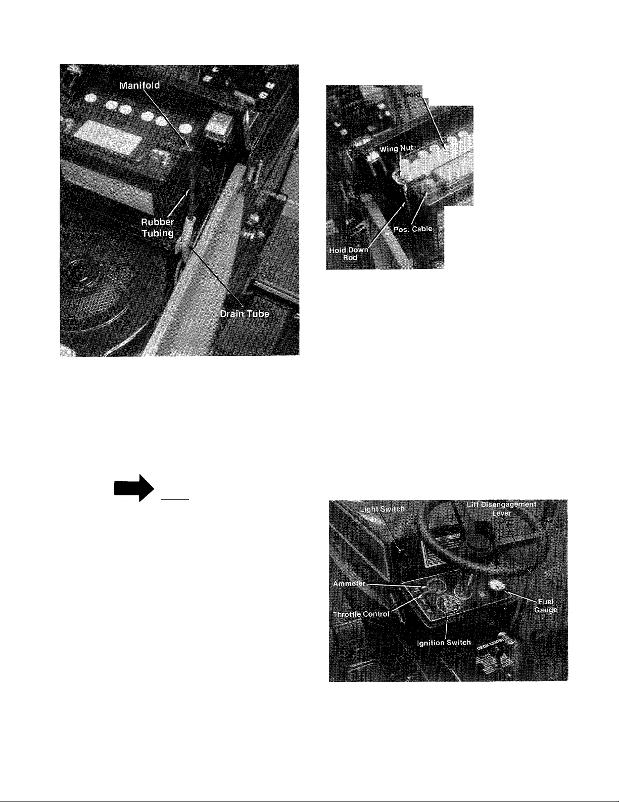
FIGURE 4.
3. Cut the black rubber tubing approximately 4
Inches long.
4. Push the rubber tubing into the manifold of
the battery and place the other end into the
drain tube. See figure 4.
Dov.n
Neg.
i . .. .■,<
FIGURES.
CONTROLS
The controls on both models may be considered
as the Drive Control and the Cutting Control as
follows:
a. Throttle Control. The throttle control is used to
regulate the engine speed and choke the engine.
The engine should be operated from % to full
throttle when operating the cutting deck or snow
thrower (optional). See figure 6.
NOTE
The vented battery allows any gases
or liquid from the battery to be car
ried to the rear of the mower through
the drain tube.
5. Hook the hold down rods under the battery
case and place the hold down over the
manifold of the battery as shown In figure 5.
6. Secure the hold down with the wing nuts.
7. Attach the positive cable (from the starter
solenoid) and the small wire (from the
ammeter) to the positive battery terminal with
the bolt, lockwasher and nut in the assembly
pack.
8. Attach the negative cable, grounded, to the
negative battery terminal with the bolt,
lockwasher and nut in the assembly pack.
FIGURE 6. CONTROLS
b. Gear Shift Lever. The gear shift lever is used to
shift into one of four Forward Gears, NEUTRAL or
REVERSE. See figures 6 and 7.
Page 7
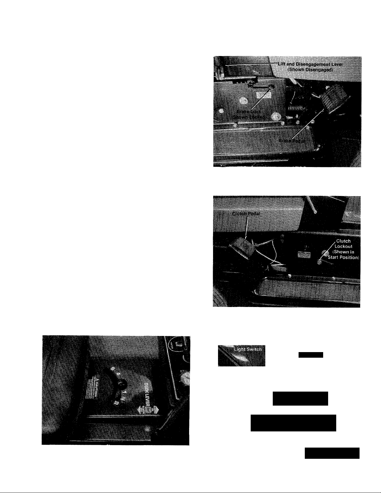
c. Brake. The brake pedal is located on the right
hand side of the mower and is operated by
depressing it with your right foot. See figure 8.
d. Brake Lock. The brake lock is located on the
right hand side of the mower. To lock the brake,
depress the brake pedal and lift up the lock
button. The pedal will stay depressed. To release,
depress the pedal. See figure 8.
e. Clutch Pedal. The clutch pedal is used to
disengage the drive mechanism. Depressing the
clutch pedal at any time will reduce mower speed.
If depressed all the way, it will stop the mower.
See figure 9.
f. Clutch Lockout. When the clutch pedal is
depressed all the way it can be locked by placing
the clutch lockout in the START position as
shown in figure 9. The clutch lockout must be in
this position before the engine will start.
g. Ammeter. (Electric Start Model Only.) The
ammeter registers the rate of battery charge or
discharge. The ammeter should register on the
plus ( + ) side when the engine is running in the
fast position until the battery is completely
charged. With a fully charged battery or with the
engine idling the ammeter will not show a charge.
See figure 10.
h. Light Switch. (Electric Start Only.) Pull the
light switch out to turn on the lights. The lights
will only operate when the engine is running. See
figure..
FIGURE 8. RIGHT HAND CONTROLS.
FIGURE 7. SHIFT PATTERN
FIGURE 9. LEFT HAND CONTROLS
Ammeter
• L * \
\ Gauge
Throttle ^ ,
Control Ignition Switch
’^¿iLift Disengagement
7 FIGURE 10. ELECTRIC START MODEL
' Lever ,
Page 8
R«coil Sta^qr
iShoiWH taeWrtjc”
k ^ Ignition Switch
I. Cutting Controls. The cutting controls consist
of the height of cut stop and the wheel height
adjusters.
Height of Cut Stop. See figure 12. Lift the stop
and set it at the desired cutting height.
r
Height of Cut Stop
FIGURE 11. RECOIL START MODEL.
i. Ignition Switch. The ignition switch is iocated
on the right side of the dashboard.
Recoil Model. See figure 11. Turn the key to the
ON position when starting the engine. To stop the
engine turn the key to the left to the OFF position
and remove the key to prevent accidental starting.
Electric Start. See figure 10. Turn the key to the
START positon to start the engine. When the
engine is running, let the key return to the ON
position. To stop the engine, turn the key to the
left to the OFF position and remove it to prevent
accidental starting.
The engine will not start unless the
clutch lockout is in the START posi
tion and the lift lever is in the DIS
ENGAGED position.
j. Recoil Starter. The recoil starter is located on
the right side of the dashboard. The recoil starter
can either be pulled while seated on the rider or
pulled while standing behind the rider. The
ignition key must be on before the engine will
start. After the engine starts, the recoil starter
handle must be returned and locked into the
dashboard before the blades or clutch are
engaged. The engine will stop if you do not follow
these instructions. See figure 11.
FIGURE 12. HEIGHT OF CUT SETTINGS
Wheel Height Adjuster. See figure 13. Move the
lever towards the wheel and set it in the desired
cutting height.
The cutting height of the mower can be set in two
different ways; FULL FLOAT position where the
deck follows the contour of the ground, and the
SUSPENDED position where the deck hangs
from the frame of the rider. The suspended
position is normally used for cutting rough
uneven ground.
To set the cutting deck in the full float position,
set the wheel height adjusters in the desired
cutting height as indicated in figure 13. Set height
of cut stop in the 1 Vz position. See figure 12.
To set the cutting deck in the suspended position,
set the height of cut stop in the desired cutting
height and then set the deck wheel so they just
dearths ground.
k. Lift and Disengagement Lever. It is used to
raise the cutting deck. Pulling it all the way back
and locking it disengages the blades. The engine
will not start unless the lift and disengagement
lever is in the disengaged position. See figure 10
S FIGUREIS. WHEEL HEIGHT ADJUSTER
Page 9
Parking Brake MUST be disengaged
before unit is put into motion.
Unit is equipped with separate brake
and ciutch pedals. To efficiently
stop, it is necessary to disengage
ciutch when applying brakes.
OPERATING
INSTRUCTIONS
STARTING THE ENGINE
Electric Start.
See figure 10. Turn the ignition key to
the START position. When the engine is
running, let the key return to the ON
position.
To stop either model, turn the key to the left to the
OFF position and remove the key to prevent
accidental starting.
A brief break-in period is essential
to ensure maximum engine and
mower life. This consists of running
the engine at half speed for a period
of time required to use one tank of
gasoline. It is also recommended to
change crankcase oil after the first 2
hours of operation.
Be sure to follow the instructions for the oil and
gasoline as described in the engine manual.
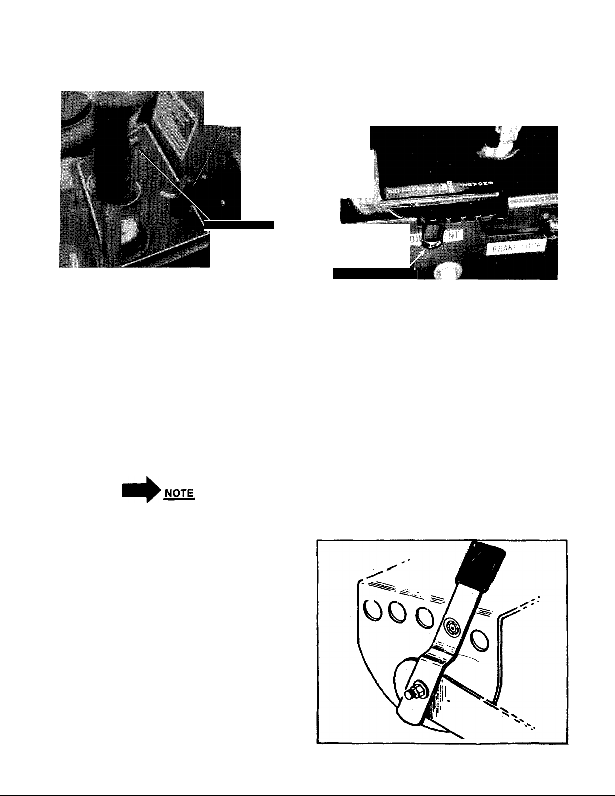
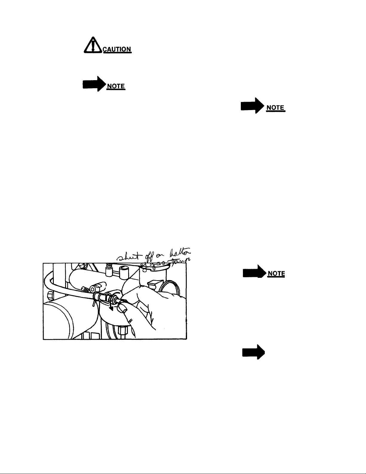
Step 1. Be sure the fuel shut-off valve is open.
See figure 14.
Step 2. Place the clutch lockout in the START
position. See figure 9.
Step 3. Place the lift and disengagement lever in
the DISENGAGED position. See figure
12.
FIGURE 14. FUEL SHUT-OFF VALVE
Step 4. Set the throttle control in the CHOKE
position. See figure 10.
Step 5. Recoil Starter.
a. Turn the ignition key to the ON
position. See figure 11.
b. Grasp the recoil starter, unlock it by
twisting it V4 turn and pull it out
sharply and hold it in the out position.
c. Slowly release the recoil starter and
lock it into the dashboard as shown in
figure 11.
STOPPING THE ENGINE
Turn the ignition key to the left to the OFF
position and remove the key to prevent accidental
starting.
OPERATING THE MOWER
Step 1. Set the desired cutting height.
Step 2. Start the engine as outlined on page 9.
Step 3. Select gear and shift.
As you become familiar with the op
eration of the mower you can move
the stop lever to a faster position.
Step 4. While holding down the clutch pedal,
move the clutch lockout lever forward.
Step 5. Put the gear shift lever into either
FORWARD or REVERSE.
'NOTE
DO NOT force the gear shift lever! If
the lever cannot be moved from
NEUTRAL to one of the drive posi
tions, release the clutch pedal slow
ly, depress it again, and then move
the gear shift lèveras required.
Step 6. Once the machine is in motion, remove
foot from the pedal. The mower will now
move ahead or to the rear, and the use of
the steering wheel will provide direction
al control.
Page 10
step 7. The mower is brought to a stop by
pressing your right foot against the brake
pedal and your left foot against the
clutch pedal. The drive belt will be disen
gaged and the brake will be applied.
A
Gear changing should be done only
after the mower has been brought to
a full stop. If the mower Is not to be
used for a long period, place the
gear shift lever in NEUTRAL and
stop the engine. DO NOT leave the
machine on an incline.
OPERATING THE CUTTER BLADE
The cutting blades may be engaged while the
mower is moving or standing still. DO NOT en
gage the cuttting blades abruptly as the sudden
belt tension on the pulley may cause the engine to
stall.
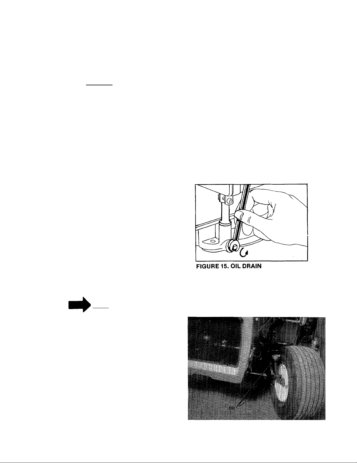
CAUTION
After the first five hours of operating a new
engine, drain the oil (see figure 15) from the
crankcase while engine is still hot and refill
crankcase with new oil; thereafter change the oil
every 25 hours of operation. This procedure
ensures for minimum wear of engine parts and
provides for virtually trouble-free operation. To
change the oii, proceed as foliows:
Step 1. With the machine on level ground, place
a suitable metal container under the oil
drain plug, then remove the drain plug.
See figure 15.
Step 2. After the oil has been drained complete-
iy from the crankcase, replace the drain
plug and tighten.
Step 3. Refill crankcase with IVa pints of good
quality, type MS, Engine oil into the
crankcase. Summer use SAE 30; Winter
(Below 40°F) use SAE 5W-20 or SAE
low.
WARNING
t
When the blade drive is engaged,
keep feet and hands away from the
discharge opening and from the
blade.
To stop the blades, move the lift and
disengagement lever (figure 10) into the DISEN
GAGED position. This raises the deck and
disengages the blades.
NOTE
When the machine is used for other
than mowing operations the blade
drive should be disengaged.
MAINTENANCE
CRANKCASE OIL
To ensure maximum engine performance, perform
the following periodic maintenance:
Oil Check
Check the oil level in the crankcase before each
use of the machine and after every five hours of
operation. Oil should b.e kept between the add and
full marks on the dipstick.
LUBRICATION
Lubricate the wheel bearings (2 per wheel) and the
upper and lower spindle bearings with SAE 30 oil
once a season. See figure 16.
FIGUREIS.
10
Page 11
The chain can be lubricated by wiping it with an
oily rag.
The differential and transmission are sealed at the
factory and require no further lubrication.
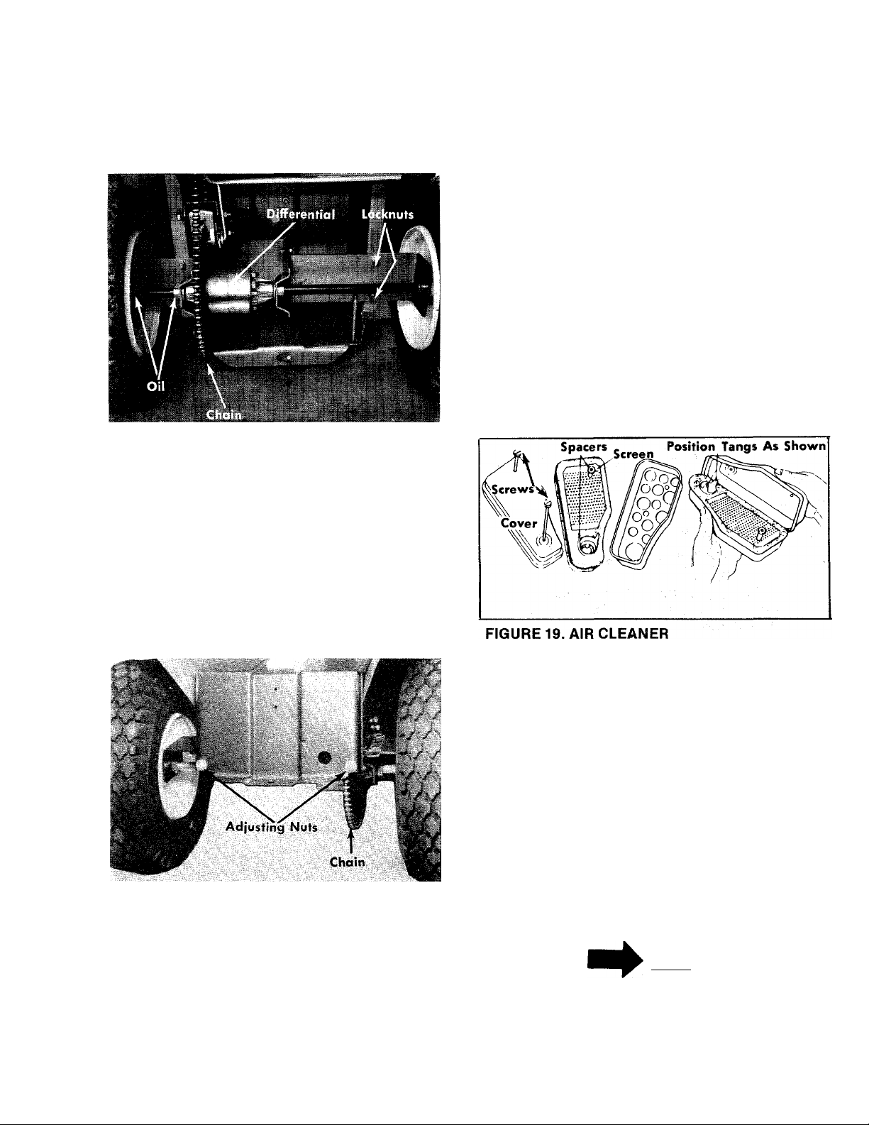
FIGURE 17. REAR AXLE ASSEMBLY
CHAIN ADJUSTMENT
To tighten the chain, loosen two locknuts on each
side of rear axie as shown in figure 17.
Tighten the adjusting nuts (figure 18) equally on
both sides. Tighten until the chain has Va inch
siack between the sprockets.
The adjusting nuts can be tightened individuaiiy
to aiign the axle.
Tighten the 4 locknuts after the adjustment is
made.
When assembling the air cleaner, make certain
the iip of the foam element extends over edge of
the air cleaner body. The foam element will form a
protective seal.
Step 1. Remove two screws and lift off complete
air cleaner assembly.
Step 2. Remove screen and spacers from foam
element.
Step 3. Remove foam element from air cleaner
body.
Step 4. a. Wash foam element in kerosene or
liquid detergent and water to remove
dirt.
b. Wrap foam in cloth and squeeze dry.
c. Saturate foam in SAE 30 engine oil,
then squeeze out excess oil.
d. Assemble parts, fasten to carburetor
with screw.
FIGURE 18. CHAIN ADJUSTMENT
AIR CLEANER
Under normal operating conditions, the air
cleaner, located on top of the carburetor, must be
serviced after every ten hours of use. Under
extremely dusty operating conditions the air
cleaner must be serviced after every hour of
operation. Refer to figure 19.
CLEANING ENGINE AND BLADE HOUSING
Any fuel or oil spilled on the machine should be
wiped off promptly. Grass, leaves, and other dirt
mustoot be left to accumulate around the cooling
fins of the engine or on any part of the machine.
Clean the underside of the blade housing after
each mowing.
BELTS
Check that belts are free of oil or dirt. Wipe the
belts periodically with a clean rag.
NOTE
Belt tension is automatically main
tained by the spring on the variable
speed bracket on the drive belts and
the belt tension on the deck belt is
maintained by the two deck springs.
11
Page 12

SPARK PLUG
WHEEL ADJUSTMENT
The spark plug gap should be cleaned and reset to
a 0.030-inch clearance every hours of engine
operation (See figure 20). Spark plug replacement
is recommended at the start of each mowing
season; check engine parts list for correct plug
type.
^NQTE
Whenever the spark plug is removed
for cleaning, it is advisable to re
place the spark plug gasket with a
new gasket.
FIGURE 20. SPARK PLUG CLEARANCE
REPLACING BLADE
The caster (forward slant of the king pin) and the
camber (tilt of the wheels out at the top) requires
no adjustment. Automotive steering principals
have been used to determine the caster and
camber on the tractor. The front wheels should
toe-in 1/8 inch.
To adjust the toe-in foilow these steps.
1. Remove the eiastic locknut and drop the tie
rod end from the wheel bracket. See figure 22.
2. Loosen the hex jam nut on tie rod.
3. Adjust the tie rod assembly for correct toe-in.
WARNING
Before beginning work on the cutter
blade, remove the spark plug from
the cylinder.
Removing and Sharpening Blades. Remove the
center bolt and lockwasher. See figure 21. Pull the
blade and blade adapter from the blade spindle.
The adapter can be removed from the blade by
removing the two adapter bolts, lockwashers and
nuts.
FIGURE 22. TIE ROD ADJUSTMENT
Dimension “B” should be approximately 118” less
than Dimension “A”. See figure 23.
A.) To increase Dimension “B”, screw tie rod into
12
tie rod end.
Page 13

B. ) To decrease Dimension “B”, unscrew tie rod
from tie rod end.
C. ) Reassmble tie rod. Check dimensions.
Readjust if necessary.
NOTE
To insure safe operation of your
unit, ALL nuts and bolts must be
checked periodicaliy for correct
tightness.
ADJUSTING CARBURETOR CHOKE
Proper choke adjustment is dependent upon
proper adjustment of remote controls on the
powered equipment.
To Check Operation of Choke-A-Matic Controls:
Move control lever to CHOKE position. (See figure
10.) The carburetor choke should be closed.
PREPARING FOR BELT REMOVAL
1
To prevent gasoline from leaking from the
engine, remove the fuel tank cap, place a
piece of thin plastic over the neck of the fuel
tank and screw on the cap.
2. Disconnect the spark plug wire and ground it
against the engine.
If the unit is equipped with a battery,
continue with Steps.
3. Remove the battery to prevent acid from
leaking.
NOTE
The air cleaner can be removed to
check the operation of the choke.
FIGURE 24. CARBURETOR ADJUSTMENT
To Adjust:
Place control lever on equipment in FAST (high
speed) position. Loosen control casing clamp
screw B. Move control casing A and wire until
lever D touches choke operating link at C. Tighten
casing clamp screw B. See figure 25.
I WARNING {
Disconnect the negatjve terminal
first and connect last when instal
ling the battery.
MOWING UNIT BELT REPLACEMENT
Step 1. Place the lift lever in the disengaged
position. See figure 10.
Step 2. Remove the belt keeper and large bolt on
the engine pulley. See figure 26.
FIGURE 26. BELT KEEPER
Step 3. Unhook the belt from the engine pulley.
See figure 27.
13
Page 14

■f
,r-
'i, .It»'.'"
FIGURE 27. REMOVING MOWER BELT
Step 4. Place the lift lever in the engaged
position. See figure 10.
Step 5. Unhook the tension springs on both
sides of the deck. See figure 27.
Deck,;, ■ ■
Links'“'...'
Deck Boll .0'
. V*-
FIGURE 29. DECK LINKS
“t'
TRANSMISSION BELTS
REMOVAL
Step 1. Place the lift lever in the disengaged
position. See figure 10.
Step 2. Remove the belt keeper and large bolt on
the engine pulley. See figure 26.
Step 3. Unhook the belt from the engine pulley.
See figure 27.
FIGURE 28. REMOVING TENSION SPRINGS
Step 6. Remove the front four deck links from the
cutting deck. See figure 29.
Step 7. Remove the belt guards from both deck
pulleys. See figure 29.
Step 8. Remove and. replace the belt and
reassemble.
Step 4. Place the lift lever in the engaged
position. See figure 10.
Step 5. Unhook the tension springs on both
sides of the deck. See figure 28.
Step 6. Remove the front four deck links from the
cutting deck. See figure 29.
Step 7. Tip the deck down as shown in figure 29.
NOTE
Leave the belt attached to the deck
pulleys unless you want to replace
it.
Step 8. Remove the engine belt guard by
removing the two front engine mounting
bolts. See figure 30.
14
Page 15

a.
Remove the entire belt guard from the
engine pulley by removing the two
front engine boits. See figure 30.
b.
Remove the transmisson pulley by
removing the hex nut and washer. See
figure 31.
c.
Remove the bolt and nut from the
steering rack and remove the belt.
Reassemble in reverse order with the
d.
new belt.
OFF-SEASON STORAGE
FIGURE 30. BELT GUARD REMOVAL
By working between the frame and
the deck, it is possible to remove
and repiace the deck belt without
removing the deck, however, the
working space is limited.
Belt Guard
If the machine is to be inoperative for a period
longer than 30 days, the following precautions are
recommended:
Step 1. Working outdoors, drain ail fuel from the
fuel tank. Use a clean dry doth to absorb
the small amount of fuel remaining in the
tank, then run the engine until all fuel in
carburetor is exhausted.
I WARNING I
C‘ # i^|>
Do not drain fuel while smoking, or
if near an open fire.
Step 2. Drain all the oil from the crankcase (this
should be done after the engine has been
operated and is still warm) and refill the
crankcase with clean new oil.
FIGURE 31. BOTTOM VIEW
Step 9. Removing the transmisión
figure 31.
Belt. See
Step 3. Disconnect the spark plug wire and
remove the spark plug from the cylinder.
Pour about six drops of engine oil into
the cylinder, and then pull the recoil
starter several times to spread the oil on
the cylinder wall. Replace the spark plug,
but DO NOT connect the wire.
Step 4. Clean the engine and the entire mower
thoroughly.
Step 5. Lubricate all lubrication points indicated
in figures 16 and 17 then wipe the entire
machine with an oiled rag in order to
protect the surfaces.
15
Page 16

TROUBLE SHOOTING CHART FOR RECOIL START MODELS
CAUTION: ALWAYS DISCONNECT SPARK PLUG BEFORE ATTEMPTING ANY REMEDY.
TROUBLE
Engine fails to start.
LOOK FOR
Safety System If the engine wili not start be sure the clutch control is dis
engaged; blade controls disengaged, the throttle control is
set and the key is turned on.
A. Disconnect the yellow wire from the engine. This comes
from the ignition switch.
B. If the engine fails to start the problem is with the engine,
not the safety system.
C. If the engine starts, the problem is with the safety system.
Check the yellow wire for a ground.
D. Check the operation of the switch behind the recoil start
er handle.
E. If the engine stops when the clutch or blade is en
gaged, the recoil handle is not pushed into the receptacle
and twisted a quarter turn.
Blocked fuel line or
empty gas tank.
Defective spark
plug.
Clean fuel line; check fuel supply. Also check fuel shut-off
valve.
Spark plug lead wire disconnected.
Faulty spark plug—spark should jump gap between control
electrode and side electrode. If spark does not jump, re
place spark plug.
NOTE: Use insulated pliers to hold the spark plug wire.
REMEDY
Hard starting or loss of
power.
Excessive vibration.
Unit fails to discharge
grass.
Engine overheats.
Throttle setting.
Loose connections
Dirty air cleaner.
Carburetor improp
erly adjusted.
Bent or damaged
blade spindle.
Discharge chute
clogged.
Foreign object
lodged in deck.
Obstructions in air
passages.
Oil level.
Throttle control lever not in the starting position.
Spark plug wire loose.
Remove air cleaner and clean as outlined in Engine
Manual.
Review paragraph Carburetor Adjustment.
Stop engine immediately; tighten all bolts and make all nec
essary repairs. If vibration continues, have the unit serviced
by a competent repairman.
Clean discharge chute artd inside of deck.
Remove object from deck. See CAUTION following step 1 in
paragraph Operation.
Remove any obstruction from air passages in shroud.
Grass and dirt in engine shroud.
Clean cooling fins.
Fill crankcase to proper oil level.
16
Page 17

TROUBLE SHOOTING CHART FOR ELECTRIC START MODEL
TROUBLE
Engine fails to start.
LOOK FOR
Safety System
Blocked fuel line or
empty gas tank.
Defective spark
plug.
REMEDY
A. Check for a blown fuse in the wire leading from the
positive terminal of the battery.
B. Before checking the safety system further, be sure the
clutch control and the blade control are disengaged; only
the starting system is being checked. Therefore remove
the spark piug lead and ground it to prevent the engine
from starting.
C. Attach a wire (minimum 18 gauge) to the positive ter
minal of the battery and touch the other end to the
small terminal (coil primary) of the solenoid. If the en
gine cranks, the problem is in the safety system.
D. Check for continuity from the battery to the solenoid.
NOTE: The positive terminal of the battery should have
a large cable (#8 guage) and a small wire (#18 gauge)
attached to it.
E. Check all wires and cable for tightness.
F. Use a #8 gauge wire and jump between the two large
terminals of the solenoid. If the unit starts, replace the
solenoid.
G. If the unit fails to start after following the above pro
cedure the problem is probably in the starting motor of
the engine.
Clean fuel line; check fuel supply. Also check fuel shut-off
valve.
Spark plug lead wire disconnected.
Faulty spark plug—spark should jump gap between control
electrode and side electrode. If spark does not jump, re
place spark plug.
NOTE: Use insulated pliers to hold the spark plug wire.
Hard starting or loss of
power.
Excessive vibration.
Unit fails to discharge
grass.
Engine overheats.
Throttle setting.
Loose connections
Dirty air cleaner.
Carburetor improp
erly adjusted.
Bent or damaged
blade spindle.
Discharge chute
clogged.
Foreign object
lodged in deck.
Obstructions in air
passages.
Oil level.
Throttle control lever not in the starting position.
Spark plug wire loose.
Remove air cleaner and clean as outlined in Engine
Manual.
Review paragraph Carburetor Adjustment.
Stop engine immediately; tighten all bolts and make all nec
essary repairs. If vibration continues, have the unit serviced
by a competent repairman.
Clean discharge chute and inside of deck.
Remove object from deck. See CAUTION following step 1 in
paragraph Operation.
Remove any obstruction from air passages in shroud.
Grass and dirt in engine shroud.
Clean cooling fins.
Fill crankcase to proper oil level.
17
Page 18

NOTES
18
Page 19

PARTS LIST FOR MODEL 136-480A ONLY
REF. PART
NO.
NO.
SCHEMATIC FOR ELECTRICAL SYSTEM
DESCRIPTION
NEW
PART
725-0269
1
725-0266
2
3
712-0121
4
710-0425
5
736-0338
6
732-0257
7
736-0225
8
Safety Switch Norm
Closed—Red
Magneto Igntion Switch
w/Nut
Wire Harness
Hex Nut #10-24
Truss Mach. Scr. #10-24 x .62
Fiber Washer
Switch Spring
internai L-wash. 5/8 i.D.
19
Page 20

136-485A
PARTS LIST FOR MODEL 136-485A ONLY
REF.
NO.
PART
NO.
1
725-0201
2 725-0267
3 725-0119
COLOR
CODE
DESCRIPTION
Ignition Key
Ignition Switch
Ammeter
4 725-0202 Headlight Switch
5 725-0486
Wire Harness N
6 725-0480 Vinyl Sealing Tape
7 725-0268 Safety Switch
8 725-0270
Solenoid
9 725-0298 Fuse7V2 Amp. V4 Dia. x
1.25 Lg.
10
725-0268
Safety Switch
NEW
PART
N
PARTS LIST FOR MODEL 136-485A ONLY
1
731-0333
2
726-0141
3
725-0453
PART
NO.
REF.
NO.
4
5 725-0^ Ì»
6 725-0480
COLOR
CODE
DESCRIPTION
NEW
PARI
Convoluted Conduit
Mtg. Clamps 3/8 I.D.
Battery 12 V.—Manifold
Vented
Battery Cable Harness
Electric Wire
Vinyl Sealing Tape N
N
20
Page 21

136-480A 136-485A
PARTS LIST FOR DIFFERENTIAL ASSEMBLY 717-0330
Ref.
No.
,'3 738-0249
8 736-0187
9
10 711-0276
11
^13
Part
No.
1
715-0247
2
748-0185
4
736-0188
5 717-0341
6
736-0119
7
710-0363
748-0158
712-0237
09133
738-0250
737-0120
Qty.
Req’d.
2
Spring Pin Spir. 3/16” Dia.
2 Gear—Doubie “D” Hoie ,,
Shaft—Long t&:8§” Lg.
1
2
FI-Wash. .760I.D. X1.49
O.D.
2
Housing Haif
2
L-Wash.5/16” Scr.*
2
Hex Scr. 5/16-24x4.00”
2
FI-Wash. .640 I.D. X 1.24
2 Gear—Round Hole
1
Drive Pin
2 Hex Cent. L-Nut 5/16-24
1
Sprocket—60 Tooth
1
Shaft—Short 9r53” Lg.
Grease—High Temp. 450®F.
2oz.
Description
X1.00” Lg.
Lg.*
O.D.
Thd.
SHORT SHAFT
New
Part
N
*For faster service obtain standard nuts, boits and washers iocaiiy. If these items cannot be obtained locally, order by part
number and size as shown on parts list.
21
Page 22

DECK LINKAGE
NOTE
Refer to illustration below for proper deck link
hook-up. if the deck is removed for any reason use
the illustraton below for correct assembly.
22
Page 23

REVERSING TRANSMISSION (PEERLESS 701)
44 36
23
Page 24

PARTS LIST FOR FIVE SPEED TRANSMISSION PEERLESS MODEL 701
REF.
NO.
1
2
3
4
5
6
7
8
9
10
11
12
13
14
15
16
17
18
19
20
27
28
29
30
31
32
33
34
35
36
37
40
41
42
43
44
PART
NO.
Pc-770061 Case, Transmission
PEt772070
PE-776164 Shaft, Output and Brake
PE-778121
PE-778122 Gear, Spur (22 teeth)
PE-778123
PE-778124
PE-778125
PE-784266
PE-786060
PE-786061
PE-776134 Shaft, Counter
PE-778109
PE-778126
PE-778127
PE-778128
PE-778129
PE-776140 Shaft, Input
PE-778113
PE-786049
PE-780105
PE-786062
PE-780072
PE-780106 Bearing, Needle
PE-792072
PE-792035
PE-780109
PE-788040
PE-784271 Rod and Fork Ass'y., Shift
PE-792073
PE-792089
PE-792077 Ball, 5/16" Steel
PE-792078
PE-792079 Spring
PE-780'l 08
PE-792074
Cover, Transmission
Gear, Spur (20 teeth)
Gear, Spur (25 teeth)
Gear, Spur (30 teeth)
Gear, Spur (35 teeth)
Collar, Shift
Sprocket (14 teeth)
Sprocket (10 teeth)
Gear, Bevel (42 tooth and 15 tooth spur gear)
Gear, Spur (20 teeth)
Gear, Spur (25 teeth)
Gear, Spur (28 teeth)
Gear, Spur (30 teeth)
Bevel Pinion, Input
Sprocket (8 teeth)
Bushing, Flanged
Chain, Roller (No. 41 chbin, 22 links)
Race, Thrust
Ring, Retaining *
Ring, Retaining
Washer
Ring, Retaining
Scr., ’^-20 X IVi hex hd. tap-tite
Key
Screw, %-16 y. % set
Washer, Thrust
Plug
DESCRIPTION
NOTE; This unit is not under warranty by
the mower manufacturer. All Part Orders
and Service must be handled through the
Local Authorized Tecumseh Service Deoler.
Find Us Fast
In The
YeHow Pages
This unit it undar warranty by TtcvmMh
Products Company. Parts and Sorvice ara
ovaiiobla through all Tacumtah, Lauton
Power Products Sarvica Oaalart. ¿hack tha
"Yallow Pagas" of your talaphona dirac-
tory under "Engines—Gasolina."
PEERLESS MODEL 701
24
Page 25

WHEELCHART
FRONT WHEEL
PART
NO.
DESCRIPTION
734-0494 Wheel Ass’y-—Comp.
734-0520 .
Rim Ass’y. Only
734-0495 Tire Only 13x5.00
734-0255 Air Valve
734-0249
Inner Tube (Service Only)
PART
NO.
734-0592
734-0594
734-0294
734-0255
734-0310
REAR WHEEL
DESCRIPTION
Wheel Ass’y.—Comp.
Rim Ass’y. Only
Tire Only 18 X ’i-B
Air Valve
Inner Tube (Servi
25
Page 26

136-480A
136-485A
RIGHT HAND VIEW
26
Page 27

J»ef.
NO.
PART
NO.
COLOR
CODE
PARTS LIST FOR MODEL 136-480A AND 136-485A
NEW
DESCRIPTION
PART
REF.
NO.
PART
NO.
COLOR
CODE
DESCRIPTION
NEW
PART
1 11263
2 710-0351
Plastic Handle (480A only)
Truss Mach. Scr. #10x .50”
Lg. (480A only)
3 710-0425
Truss Mach. Scr. #10-24 x
.62” Lg.(480Aonly)
4 736-0338
712-0121
5
Fiber Wash. (480A only)
Hex Nut #10-24 Thd.* (480A
only)
6 11053 Switch Brkt. Ass’y- (480A
only)
7
712-0147
Speed Nut #10-24 U-Type
(480A only)
725-0266
8
9 732-0257
10 725-0128
712-0287 Hex Nut 1/4-20Thd.* (485A
11
Ignition Switch (480A only)
Switch Spring (480A only)
Ignition Key (480A only)
only)
12 736-0329
L-Wash. 1/4” Scr. *(485A
only)
13 710-0258
Hex Scr 1/4-20 X. 62” Lg.*
(485A only)
14 711-0222
Battery Hold Down Rod
(485A only)
725-0453 Battery 12-volt Manifold
15
Vented (485A only)
16
712-0113
Wing Nut Solid V4-20 Thd.
(485A only)
1 17
12614 Battery Hold Dow'n (485A
only)
18 731-0333
Convoluted Conduit (485A
only)
710-0286 Truss Mach. Scr. V4-20 x
19
.50” Lg. (485A only)
20 736-0329
L-Wash. 1/4” Scr.* (485A
only)
21
712-d^
Hex Nut 1/4-20 Thd.*(485A
only)
22
710-0258
Hex Scr. 1/4-20 X.62” Lg.*
(485A only)
23 12811
Battery Brkt. Brace (485A
only)
24 736-0329
L-Wash. 1/4” Scr.* (485A
only)
712-0287 Hex Nut 1/4-20 Thd.* (485A
25
only)
26
12747
Battery Brkt. (485A only)
27 710-0289 Hex Scr. 1/4-20 X.50” Lg.*
28 723-0296 Hood Latch Ass’y-
29 736-0329 L-Wash. 1/4” Scr.*
712-0287
30
Hex Nut V4-20Thd.*
31 11027 Handle Stop Brkt. Ass’y.
32 726-0121 Push Cap V4” Dia. Black
736-0192
33
FI-Wash. .531 I.D. xl.13
O.D.
34 712-0287
Hex Nut 1/4-20 Thd.* (485A
only)
35 736-0329, L-Wash. 1/4” Scr.* (485A
only)
36 Head Lamp Bezel (485A
only)
N
37 Head Lamp Retainer (485A
only)
N
12781 Head Lamp Bezel (480A
only)
N
38 714-0101 Inter. Cot. Pin 1/2” Dia.
39 10346
40 720-0157
Lockout Link Ass’y.
Grip
41 749-0212 Lift Handle
42 11032
43 736-0219
Lift Handle Brkt. Ass’y.
Bel I.-Wash. .400 I.D. x1.130
O.D.
44
710-0201 Hex Scr. 3/8-16 X.62” Lg.*
45 11029
Handle Pivot Brkt.
46 735-0180 Rubber Wash. .75 I.D. x
1.25 O.D.
47 748-0201
Spacer .635 I.D. x .88 O.D.
X .57
10904
48
Deck Link Ass’y.
49 710-0195 Hex Scr. 1/4-28 X.62” Lg.*
711-0577
50
51 726-0106
52
11399 Adapter Plate Ass’y.
Pivot Pin
Push-on Flange Palnut
53 732-0261 Torsion Spring
54 11574
Chute Cover Ass’y.
55 10349 Deck Link Ass’y.
56 710-0627
57 736-0242
Hex Scr. 5/16-24 X .75” Lg.*
Bell.-Wash. .345I.D. x.88
O.D.
734-0592
N
58
Rear Wheel Ass’y.—Comp.
18x6.50-8
59
738-0140 Shid. Scr. .437 Dia. x .180
736-0264
N
60
61 712-0267
62 09735
FI-Wash. .344 I.D. x .62 O.D.
Hex Nut 5/16-18 Thd.*
Connecting Rod 3/16x1 x
12.5” Lg.
09721
63
Pivot Link Ass’y.
*For faster service obtain standard nuts, bolts and washers locally. If these items cannot be obtained locally, order by part
number and size as shown on parts list.
(462—Red Flake)
When ordering parts if color or finish is important, use color code shown at left,
(e.g. Red Flake Finish—11839 (462).)
27
Page 28

co co
o> o>
I I
È
00 00
СЛ о
>>
IO
00
<0 Od
Cb \)
Page 29

PARTS LIST FOR M
REF.
NO.
1 731-0220
2 712-0158
736-0242
" 3
PART
NO.
COLOR
CODE
DESCRIPTION
Steering Wheel Cap
Hex Cent. L-Nut 5/16-18 Thd
Bell.-Wash. .345I.D.X.88
O.D.
4 731-0219
750-0319
5
722-0115
6
710-0351
7
Steering Wheel
Steering Tube
Knob—Throttle Control
Truss Mach. Scr. #10 x .50”
Lg.*
746-0160 Throttle Control Ass’y-
8
Comp.
9 12790
710-0599
10
Upper Frame Cover
Hex C-Tap Scr. V4-20 x .50”
Lg.
757-0264 Seat Assembly
11
12
13
15
736-0921
712-0206
710-0198
L-Wash. V2”Scr.*
Hex Nut 1/2-13Thd.*
Hex Sems Scr. 5/16-18 x
.75” Lg.*
736-0119
16
712-0267
17
11839
18
19 710-0259
L-Wash. 5/16” Scr.*
Hex Nut 5/16-18 Thd.*
Rear Fender
Hex Sems Scr. 5/16-18 x
.62” Lg.*
20 11090
21 723-0241
22 712-0798
736-0105
23
Frame Assembly
Foot Pad 15.75x4.00”
Hex Nut 3/8-16 Thd.*
Bell.-Wash. .400I.D. x.88
O.D.
24 738-0317
12748
25
748-0227
26
27 748-0237
736-0264
28
29 748-0236
30 710-0180
31 736-0tJ3'
710-0494
32
S'
Steering Shaft
Steering Gear Support
Hex Flange Bearing .630 I.D.
Pinion Gear
FI-Wash. .344 I.D. x .62 O.D.
Side Gear
Hex Scr. 3/8-24 X .75” Lg.*
FI-Wash. .406 I.D. X 1.25
O.D.
Sq. Hd. Set Scr. 5/16-18 X
.38 Cup
34
35
711-0169
734-0494
Collar5/8” I.D.
Front Wheel Ass’y-—Comp.
13x5.00
723-0156
36
37 712-0711
711-0613
38
736-0156
39
Ball Joint Ass’y. 3/8-24 Thd.
Hex Jam Nut 3/8-24 Thd.
Tie Rod
FI-Wash. .6351.D.x 1.20
O.D.
40
41
748-0151
710-0670
Flange Brg.w/Flats.75 I.D.
Hex Nylon Scr. 3/8-16 X
1.25” Lg.
42 12749
43 736-0%aS“
44 710-0180
747-0186
45
714-0507
46
Steering Arm Shaft Ass’y.
Fi-Wash. .406 I.D.x 1.25 O.D.
Hex Scr. 3/8-24 X.75” Lg.*
Steering Rod
Cotter Pin 3/32” Dia. X.75”
Lg.*
712-0923
47
48 736-0158
12406
49
c, 50
712-0711
12755
51
52 736-0169
j
________________
*For faster service obtain standard nuts, boits and washers
iocaily. If these items cannot be obtained locally, order by
part number and size as shown on parts list.
Hex Cent. L-Nut 5/8-16 Thd.
L-Wash. 5/8” Scr.*
Front Pivot Bar Ass’y.
Hex Jam Nut 3/8-24 Thd.
Axle Ass’y.—Front R.H.
L-Wash. 3/8” Scr.*
L136-480AAND 136-4
ODE
NEW
PART
REF.
NO.
53
PART
NO.
712-0241
54 12752
COLOR
CODE
35A
DESCRIPTION
Hex Nut 3/8-24 Thd.*
Axle Ass’y.—Front L.H. N
55 748-0193 Spacer .380 I.D.x .630 O.D.
X .575 Lg.
56 12411 Front Pivot Bracket
57 710-0622
N
58 12791
59
■\
60 712-0121
61
62
N
✓
710-0192
736-0722 L-Wash. #10 Scr.*
12782 Lower Side Panel R.H.
Hex Scr. 5/8-18x1.62” Lg.*
Grille Screen N
Truss Scr. #10-24 X .375”
Lg.*
Hex Nut #10-24Thd.*
63 12781 Lower Grille Panel
64
65
712-0375
12814
Hex Cent. L-Nut 3/8-16 Thd.
Front Grille Upper Ass’y.
(485A only)
12808 Front Grille Upper (480A
only) N
66 727-0199 Hood Stop
67
736-0463 FI-Wash. .25 I.D. x .62 O.D.
68 736-0722 L-Wash. #10 Scr.*
69 712-0121 Hex Nut #10-24 Thd.*
70 736-0101
FI-Wash. .380 I.D. X 1.00
O.D.
71
735-0126 Rubber Wash. .3? ^ x .87
O.D.
72
710-0253 Hex Scr. 3/8-16 X i
73
710-0258 Hex Scr. V4-20X.62” Lg.
74
12780
75 723-0155 Fuel Gauge—Cap
N
76 735-0179
N
Front Hood
Rubber Grommet (Fuel Tank
Neck)
77
731-0345 Dash Panel Insert (480A
only) N
N
731-0346 Dash Panel Insert (485A
only) N
78 12795 Dash Panel Ass’y. (480A
only) N
12798 Dash Panel Ass’y. (485A
only)
79 712-0222
80
72&=048O Vinyl Sealing Tape'^'=‘ ''s
81 12784
—462 Side Panel R.H.
82 712-0287
Speed Nut Push On 5/8” Dia.
Hex Nut 1/4-20 Thd.*
83 736-0329 L-Wash. 1/4” Scr.*
84
12785 —462 Side Panel L.H.
85 710-0621
86 12783 —462
87 726-0157
712-0147
88
89 751-0182 Fuel Tank
N
90
N
732-0255 Seat Spring 4.50” High
91 751-0183
92
710-0289
93 11852
N
94
751-0173 Fuel Line
95 751-0171
96 735-0149
97
710-0342
Hex Scr. 5/16-18 X.50” Lg.*
Lower Side Panel L.H.
Speed Nuti /8” Stud
Speed Nut #10-24 “U”-Type
Engine Brace
Hex Scr. 1/4-20 X.50” Lg.*
Upper Frame
Fuel Shut-Off Valve
Bushing—Fuel Tank (Valve)
Hex Scr. 3/8-16x1.25” Lg.*
98 725-0270 Solenoid (485A only)
99 736-0222
N
100 748-0228
(462—Red Flake)
When ordering parts, if color or finish is important use the
Ext. L-Wash. 1/4”Scr.*
(485A only)
Hex Flange Brg. .5(X)” I.D.
29 appropriate color code shown above (e.g. Red Flake
Finish—11839(462).)
NEW
PART
N
N
N
N
N
i^^N
N
N
N
N
N
Page 30

136-480A 136-485A
NOTE: If for any rea
son disc brake is dis
assembled, be sure
round end of push
pin (Ref. No. 97) is
toward the cam lever
(Ref. No. 93).
FRAME VIEW
30
Page 31

PARTS LIST FOR MODEL 136-480A AN
NO.
....
COLOR
CODE
DESCRIPTION
Enqine
Hex Scr. 5/16-18x1.50” Lg.*
Part of Engine
Muffler Strap
L-Wash.5/16” Scr.*
Hex Nut 5/16-18 Thd.*
Hex Drill Scr. #10x.50” Lg.
L-Wash. 1/4” Scr.*
Hex Scr. 1/4-20 X .62” Lg.* Lg.
Hose Clamp
Muffler w/1.120 I.D. Inlet
Clutch Pedal Pad
Clutch Pedal Ass’y.
Cotter Pin 3/32” Dia. x .75”
REF.
PART
NO.
1
710-0442
^ 3
4 751-0188
5 736-0119
712-0267
6
710-0456
7
736-0329
8
710-0258
9
751-0186 Exhaust Pipe Ass’y-
10
11 726-0132
751-0190
12
11057 Parking Brake—Lever Ass’y-
13
14 12379
11037
15
714-0507
16
Lg.*
17
18
19
20
12654
11090
712-0267
736-0105
Belt Guard Ass’y. —Engine
Frame Ass’y.
HexNut5/16-18Thd.*
Bell.-Wash. .400I.D. X.88
O.D.
21 738-0215
Shid. Scr. .489” Dia. x 3.00”
Lg.
22 710-0259
Hex Sems Scr. 5/16-18 x
' .62” Lg.*
23 12160
24 747-0112
25 12448
26 712-0158
27 12806
X
712-0375
28
29 711-0630
Belt Keeper Ass’y.
Clutch Rod
Idler Brkt. Ass’y.
Hex Cent. L-Nut 5/16-18 Thd
Parking Brake—Lever
Ass’y.
Hex Cent. L-Nut 3/8-16 Thd.
Spacer .380 I.D. x .50 O.D. x
.562
30 11039
750-0298
31
32 736-0119
712-0267
33
34
710-0193
Pedal ‘‘U”-Brkt. Ass’y.
Spacer .384 1.D. x .500 O.D.
X1.43” Lg.
L-Wash. 5/16” Scr.*
Hex Nut 5/16-18Thd.*
Hex Sems Scr. 5/16-18 x
.75” Lg.*
35 11845
710-0194
36
37 714-0129
Transmission Belt Guard
Hex Scr. 3/8-16 X 3.00” Lg.*
#4Hi-ProKey3/32”x5/8”
Dia. Hdn.
712-0287
38
736-0329
39
40 761 -0148
Hex Nut 1/4-20 Thd.*
L-Wash. 1/4” Scr.*
Blade Brake Ass’y. 1.38”
High
41 710-0198
Hex Sems Scr. 5/16-18 x
.75” Lg.
42 12813
43 12378
710-0134 Carriage Bolt V4-20 x .62”
44
Brake Pedal Ass’y.
Brake Pedal Pad
Lg.*
726-0121
45
712-0267
46
47 736-0119
48 738-0140
- 49
732-0245
Push Cap Va” Dia. Black
Hex Nut5/16-18Thd.*
L-Wash. 5/16” Scr.*
ShId. Scr. .437 Dia. x .180
Extension Spring .90 O.D.
X3.75” Lg.
'For faster service obtain standard nuts, bolts and washers
locally. If these items cannot be obtained locally, order by
part number and size as shown on parts list.
NEW
PART
N
N
N
N
N
D 136-485A
REF.
PART
NO.
50 736-0119
NO.
COLOR
CODE
DESCRIPTION
L-Wash. 5/16” Scr.*
51 712-0267 Hex Nut 5/16-18 Thd.*
52 732-0191
53 736-0119
Spring .75 O.D. x 11.00” Lg.
L-Wash. 5/16” Scr.*
54 712-0267 Hex Nut 5/16-18 Thd.*
55 710-0322 Hex Sems Scr. 5/16-18 x
1.00” Lg.*
56 747-0106 Brake Rod .25” Dia. x 23.50”
57 710-0198 Hex Sems Scr. 5/16-18 x
.75” Lg.*
58 10398 Disc Brake Brkt. Ass’y.
712-0287 Hex Nut 1/4-20Thd.*
59
60 736-0329
61 10410
62
710-0258
L-Wash. 1/4” Scr.*
Spring Brkt.
Hex Scr. 1/4-20 X .62” Lg.*
63 713-0163 #420 Chain Vz” Pitch x 79
Links
64 741-0199 Plastic Flange Brg. w/Flats
65 10364 Rear Axle Plate
710-0437 Chain Adj. Link 5/16-18 x
66
4.38” Lg.
67
712-0429 Hex Ins. L-Nut 5/16-18 Thd.
732-0157
68
Spring .38 O.D. x 3.25” Lg.
69 10360 Axle Bolt Plate Ass’y.
10362 Rear Axle Brkt. Ass’y.
70
71 710-0198
Hex Sems Scr. 5/16-18 x
.75” Lg.*
72 736-0119
L-Wash. 5/16” Scr.*
73 712-0267 Hex Nut 5/16-18 Thd.*
74 710-0412 Hex Scr. 1/4-28 X .75” Lg.
736-0242
75
Bell.-Wash. .345 I.D. x.88
O.D.
710-0237 Hex Scr. 5/18-24 X.62” Lg.*
76
77 735-0126 Rubber Wash. .33 I.D. x .87
O.D.
712-0158
78
Hex Cent. L-Nut 5/16-18 Thd.
79 736-0159 FI-Wash. .344 I.D. x.88 O.D.
80 11846 Shift Lever Brkt. Ass’y.
81 11545
82
720-0165
Shift Lever
Knob (For Transmission
Lever)
83 736-0329 L-Wash. 1/4” Scr.*
84
712-0138 Hex Nut 1/4-28 Thd.
12797
85
761-0137 Disc Brake Ass’y.—Comp.
86
87
710-0316 Hex Scr. 3/8-16x3.50” Lg.*
88 761 -0138 Spacer for Disc Brake 5/8
transmission Support Brkt.
O.D.
HH-12-03045 Casting—Carrier Side
89
90
HH-11
-03436
Spacer
91 HH-12-03041 Casting—Cam Side
92
712-0375 Hex Cent. L-Nut 3/8-16 Thd.
93 HH-18-02770
94
HH-03-03032 Thrust Wash. 5/16” I.D.
712-0134 Hex Top L-Nut
95
Cam Lever
96 HH-06-03031 Spring
97 HH-05-03034 Push Pin
HH-03-03097 Disc—Back Up
98
99 HH-15-02533
(462—Red Flake)
When ordering parts, if color or finish is important us® the
31
appropriate color code shown above (e.g. Red Flake
Finish—11839(462).)
Pad—Friction
NEW
PART
N
N
Page 32

136-480A
136-485A
IMPORTANT
Belts listed by Part Number are of
special construction and should be
used when replacement is necessary.
The dimensions and description given
are for general reference only and belts
purchased by description and dimen
sion generally will only provide tempo
rary service.
DECK VIEW
32
Page 33

PART
REF.
L,no.
1
756-0174
NO.
COLOR
CODE
Transmission Split Pulley
.50 I.D.
2 712-0261
736-0158
3
4 754-0191
5 756-0124
754-0151
6
756-0253
7
736-0235
8
Hex Jam Nut 5/8-11 Thd.
L-Wash. 5/8” Scr.* C.D.
“V”-Belt Vz x65” Lg. 34
Deck Pulley 4.75” O.D.
“V”-Belt21 /32x67” Lg.
Two Step Engine Pulley
FI-Wash. .406 I.D. X 1.25
O.D.
9
10
11
12
13
14
736-0169
710-0152
12672
09164
12674
710-0322
L-Wash. 3/8” Scr.*
Hex Scr. 3/8-24x1.00” Lg.*
Belt Guard—L.H.
Deck Reinforcement Plate
34” Deck Ass’y. 42
Hex Sems Scr. 5/16-18 x
1.00” Lg.* 44 732-0307 Spring (Deck)
710-0289
15
712-0123
16
17 736-0119
742-0120
18
710-0117
19
Hex Scr. V4-20X.50” Lg.*
Hex Nut 5/16-24 Thd.*
L-Wash. 5/16” Scr.*
17” Blade 47 09321
Hex Scr. 5/16-24x1.00” Lg.
H.T. C.D.
20
710-0459
Hex Scr. 3/8-24 X1.50” Lg.
H.T.
736-0217
21
22 10769
710-0289
23
4 24
711-0571
11399 Adapter Plate Ass’y-
25
710-0195
26
27 732-0261
11574
28
726-0106
29
736-0329
30
L-Wash. 3/8” Scr. H.D.
Blade Adapter Kit 52
Hex Scr. 1/4-20 X.50” Lg.* 53 756-0217 Fl-ldler 2.75” C.D.
Pivot Pin
Hex Scr. 1/4-28 X.62” Lg.* 56 712-0922
Torsion Spring
Chute Cover Ass’y.
Push Nut 1/4” Rod
L-Wash. 1/4” Scr.*
PARTS LIST FOR MODEL 136-480A AND 136-485A
DESCRIPTION
NEW
PART
REF.
NO.
PART
NO.
712-0287 Hex Nut 1/4-20 Thd.*
31
32
10949
COLOR
CODE
33 736-0105
712-0116 Hex Ins. L-Nut 3/8-24 Thd.
35 738-0119 Shid. Scr. .625” Dia. xl.75”
36 734-0295 Wheel Ass’y. 5.0” Dia.
37 736-0105 Bell.-Wash. .400I.D. x.88
10937
38
11236 Wheel Brkt. Ass’y.—R.H .
39
40 736-0329
41 712-0287 Hex Nut 1/4-20 Thd.*
12673
43 711-0255 Blade Spindle
45 714-0365
46 08253
48 741-0919
49 736-0329
50 712-0287 Hex Nut 1/4-20 Thd.*
11237
51
712-0116 Hex Ins. L-Nut 3/8-24 Thd.
54
756-0116
55 09322 Blade Brake Disc
57
736-0921 L-Wash. 1/2” Scr.*
58 11917 34” Deck Ass’y. Comp.
"2 % *'^■3
DESCRIPTION
Spring Lever Ass’y. w/Knob
Bell. Wash. .400 I.D. x .88
Lg.
C.D.
Wheel Pivot Bar
L-Wash. 1/4” Scr.*
Belt Guard—R.H.
#6Hi-Pro Key 5/32” X 5/8”
Dia.
Bearing Housing
Blade Spindle Ass’’.'. Comp.
Ball Brg. .787 I.D «‘i
L-Wash. 1/4” Scr.*
Wheel Brkt. Ass’y. L.H.
“V”-Belt ldler3.06”C.D.
Hex Jam Nut 1/2-20 Thd.
(For Service Cniy)
1i
NEW
PART
*For faster service obtain standard nuts, bolts and washers locally. If these items cannot be obtained locally, order by part
number and size as shown on parts list.
(462—Red Flake)
When ordering parts if color or finish is important, use color code shown at left,
(e.g. Red Flake Finish—11839(462),)
33
Page 34

PARTS INFORMATION
POWER EQUIPMENT PARTS AND SERVICE
BRIGGS & STRATTON, TECUMSEH AND PEERLESS
PARTS AND SERVICE
Ports and service for all MTD manufactured power
equipment are available through the authorized service
firms listed below. All orders should specify the model
number of your unit, parts numbers, description of parts
and the quantity of each part required.
ALABAMA BIRMINGHAM
Auto Electric&Carburetor Co...2625 4th Ave. S.......................... 35233
ARKANSAS NORTH LITTLE ROCK
Sutton's Lawn Mower Shop
Mity Mite Motors, Inc; .....................2515 Towson Ave
CALIFORNIA SAN BERNARDINO
Lawn Mower Supply Co................... 25608 E. Baseline .... 92410
J.W. Jewett Co.................................. 981 Folsom St......................94107
Luttig 8i Severson ........................... 2030 28th St....................... 95818
COLORADO DENVER
South Denver Lawn Equip
CONNECTICUT SUFFIELD
The Jones 8i Ramsey Co
FLORIDA JACKSONVILLE
Rodeo Distributors
Moz-AII of Florida, Inc
GEORGIA EAST POINT
East Point Cycle & Key
ILLINOIS !
Keen Edge
INDIA‘S' ■ ELKHART
^ & Sales Inc
Brown Equip. Dist., Inc
IOWA DUBUQUE
Power Lawn 8i Garden Equip. .2551 J.F. Kennedy —52001
KANSAS WICHITA
Hixon, Inc
LOUISIANA NEW ORLEANS
Suhren Engine Co
MARYLAND ТАКОМА PARK
Center Supply Co
MASSACHUSETTS SPRINGFIELD
Morton B. Collins Co
MICHIGAN MOUNT CLEMENS
Power Equipment Dist
Lorenz Service Co
MINNESOTA MINNETONKA
Hance Distributing Inc......................11212 Wayzata Blvd. ..55343
MISSISSIPPI BILOXI
Biloxi Sales & Service, Inc. ....506 Caillavet St
MISSOURI KANSAS CITY
Automotive Equip. Service
Henzier, Inc
NEBRASKA OMAHA
R.P.W., Inc
............................
...........................................
.............................
..........................
.............................
.......................................
.........................................
.............
FORT SMITH
SAN FRANCISCO
SACRAMENTO
..............
..................
..........................
CORAL GABLES
.....................
..........
......... 2834 Church St....................30344
...............
CORYDON
....................
.......................
.....................
LANSING
..............
ST. LOUIS
Rt. 4, Box 368
527 West Evans
850 Thompsonvi He Rd. 06078
2403 Market St
365 Greco Ave
8615 Ogden Ave
2101 Industrial Pkwy. ..46514
110 Beech St
3030 Mascot
8330 Earhart Blvd
6867 New Hampshire Ave. 20012
300 Birnie Ave
36463 South Gratiot... 48043
2500 S. Pennsylvania.. 48900
3117 Holmes St
2015 Lemay Ferry Rd. 63125
7402 "L" St......................... 68127
...................
..............
..................
..................
....................
.................
.......................
.....................
..............
.....................
............................
..................
72117
72901
80223
32206
33146
60534
47112
67204
70118
01107
39533
64109
Briggs & Stratton, Tecumseh and Peerless parts anV
service should be handled by your nearest authorize
engine service firm. Check the yellow pages of your
telephone directory under the listing Engines
Goso/irae, Briggs & Stratton or Tecumseh Lauson
NEW YORK CARTHAGE
Gamble Dist., Inc
Kimber's, Inc......................................115 N. Geddes St
Henry W. O'Neil8> Associates ..410 N. Goodman St. ... 14609
NORTH CAROLINA GREENSBORO
Dixie Sales Company
Smith Hordware Co
OHIO WADSWORTH
National Central .................................687 Seville Rd,
Bleckrie, Inc
Stebe's Mid-State Mower Supply Box 366
Sunshine Wholesale Tire Outlet Route 224.................................44890
McClure Lawn & Garden Supply...1114 Lexington Ave. . 44903
OKLAHOMA MUSKOGEE
Victory Motors, Inc
Ada Auto Supply
OREGON PORTLAND
Kenton Supply Co
PENNSYLVANIA LANCASTER
Raub Supply Co................................ James8iMulberry Sts...17604
Bluemont Co
TENNESSEE KNOXVILLE
Master Repair Service
Memphis Cycle & Supply Co
American Sales 8t Service, Inc.. 1922 Lynnbrook
TEXAS DALLAS
Marr Brothers, Inc............................ 423 E. Jefferson ..................75203
Bullard Supply Co
Catto & Putty, Inc............................. P.O. Box 2408
Woodson Sales Corp
UTAH SALT LAKE CITY
A-1 Engine & Mower Co.................. 437 E. 9th St
VERMONT BURLINGTON
Vermont Appliance Co.......................44 Lakeside Ave
VIRGINIA RICHMOND
RBI Corp............................................. 963 Myers St
WASHINGTON SEATTLE
Bailey’s Rebuild, Inc
WEST VIRGINIA CHARLESTON
Young's, Inc........................................233 Virginia St., E. ...25301
WISCONSIN APPLETON
Automotive Supply Co
...............................
SYRACUSE
ROCHESTER
.......................
GOLDSBORO
..........................
.......................................
....................................
CLEVELAND
CARROL
WILLARD
MANSFIELD
...........................
ADA
....
..........................301 E. 12th St..................... 74820
..............................
PITTSBURGH
....................
MEMPHIS
HOUSTON
........................ 2409 Commerce St
SAN ANTONIO
FORT WORTH
........................
........................
.....................
West End Ave
327 Battleground Ave.. 27402
515 N. George St
7900 Lorain Ave
605 S. Cherokee
8216 N. Denver Ave. . 97217
11125 Frankstown Rd.. 1523f' 2423 Broadway, N.E. ..37917
...........
421 Monroe Ave..................38103
1702 N. Sylvania ............. .76111
1325 E. Madison St. ...98102
123 S. Linwood Ave. ..54911
-------------------------
-----------------
....................
..............
.............
...............
.................
.................................
.............
......................
................
....................
.......................
................
......................
13619
13204
27530
44281
44102
43112
74401
38117
77003
78206
84111
05401
23260
WARRANTY PARTS AND SERVICE POLICY
The purpose of warranty is to protect the customer from defects in workmanship and materials, defects which are NOT detected
at the time of manufacture. It does not provide for the unlimited and unrestricted replacement of parts. Use and maintenance are
the responsibility of the customer. The manufacturer cannot assume responsibility for conditions over which it has no control.
Simply put, if it's the manufacturer’s fault, it's the manufacturer’s responsibility; if it's the customer's fault, it’s the customer’s
responsibi lity.
CLAIMS AGAINST THE MANUFACTURER'S
WARRANTY INCLUDES
1. Replacement of Missing Ports on new equipment. 1. Model Number of unit involved.
2. Replacement of Defective Parts within the warranty period. 2. Dote unit was purchased or first put into service.
3. Repair of Defects within the warranty period. 3. Dote of failure.
All claims MUST be substantiated with the following
information:
4. Nature of failure.
 Loading...