

FP1
Titan Tube
User Manual

Astera LED Technology GmbH
User Manual for FP1 Titan Tube 2019-01-21
1 CONTENTS
2 Package Contents ............................................................................................................................................... 5
3 CE and FCC Conformity ..................................................................................................................................... 5
4 Safety and Handling ............................................................................................................................................ 6
4.1 Mounting Accessories ................................................................................................................................ 8
4.2 Battery ......................................................................................................................................................... 10
4.3 Battery Icon ................................................................................................................................................ 10
4.4 Charging ..................................................................................................................................................... 11
4.5 AC and DMX Wiring .................................................................................................................................. 12
4.6 PowerBox Button and Status LED ........................................................................................................... 13
5 Specification ....................................................................................................................................................... 15
6 Troubleshooting .................................................................................................................................................. 16
7 Operation ............................................................................................................................................................ 17
7.1 Ship Mode .................................................................................................................................................. 17
7.2 AsteraRGB Color Space ........................................................................................................................... 17
7.3 Ways to Control ......................................................................................................................................... 18
7.4 Control By Infrared with ARC1 ................................................................................................................ 18
7.5 Control by the AsteraApp™ ................................................................................................................... 19
7.6 Control by Wireless DMX .......................................................................................................................... 19
7.7 Control by wired DMX .............................................................................................................................. 19
7.8 Control Panel ............................................................................................................................................. 20
7.9 Blue Mode .................................................................................................................................................. 20
7.10 Status Screen ............................................................................................................................................. 21
7.11 Main Menu Options .................................................................................................................................. 22
7.12 Input Select ................................................................................................................................................ 23
7.13 Select a Static Color ................................................................................................................................. 24
7.14 DMX Settings .............................................................................................................................................. 25
7.15 Dimmer Curve............................................................................................................................................ 25
7.16 Runtime ....................................................................................................................................................... 26
7.17 Unpair CRMX .............................................................................................................................................. 27
7.18 Standalone ................................................................................................................................................. 28
7.19 AC Failure(Emergency Light) .................................................................................................................. 30
7.20 DMX Failure ................................................................................................................................................ 30
7.21 Info ............................................................................................................................................................... 31
7.22 Reset Settings ............................................................................................................................................. 31
7.23 Adjust Color via the Color Palette Button ............................................................................................. 32
7.24 Adjust Brightness or Runtime via the Brightness Button ...................................................................... 33
8 Using the Light with the AsteraApp™ ............................................................................................................. 34
8.1 Pair your Light with the AsteraApp™ ..................................................................................................... 34
8.2 Powerful Light Control .............................................................................................................................. 35
8.3 Change the Color ..................................................................................................................................... 35
8.4 Create a Set ............................................................................................................................................... 36
8.5 Targeting Lights.......................................................................................................................................... 37
8.6 Changing The Effect................................................................................................................................. 38
8.7 List of Effects ............................................................................................................................................... 39
8.8 Chaser Effects in Depth ........................................................................................................................... 40
8.9 The Main Screen ........................................................................................................................................ 41
8.10 Brightness .................................................................................................................................................... 42
8.11 Runtime ....................................................................................................................................................... 43
8.12 Anti-Flicker .................................................................................................................................................. 43
8.13 Theft Alarm ................................................................................................................................................. 44
8.14 Enter and Leave Standby ........................................................................................................................ 45
8.15 DMX Settings .............................................................................................................................................. 46

Astera LED Technology GmbH
User Manual for FP1 Titan Tube 2019-01-21
Page | 3
59: RGBWS RGBWS (PIXEL = 16; STROBE = MULTIPLE) ....................................................................................... 143
60: RGBAWS RGBAWS (PIXEL = 16; STROBE = MULTIPLE) ................................................................................. 147
61: DIM RGBS DIM RGBS (PIXEL = 16; STROBE = MULTIPLE) .............................................................................. 151
62: DIM RGBWS DIM RGBWS (PIXEL = 16; STROBE = MULTIPLE)....................................................................... 155
63: DIM RGBAWS DIM RGBAWS (PIXEL = 16; STROBE = MULTIPLE) ................................................................. 159
64: RGB CCT DIM IND S (PIXEL = 16; STROBE = MULTIPLE) ............................................................................... 164
LEE Color Gels ........................................................................................................................................................ 172
11 Version History ................................................................................................................................................... 176

Astera LED Technology GmbH
User Manual for FP1 Titan Tube 2019-01-21
Page | 4
Contact Information
Astera LED Technology GmbH
Stahlgruberring 36
81829 Munich
Germany
+49 89 2155253-0
Technical support
Europe: +49 89 21552253-1
USA: +1 954 578 8881
Asia: +86 755 28237295
Email: service@astera-led.com
©2019, Astera LED Technology GmbH
All rights reserved

Astera LED Technology GmbH
Titan Tube
Floorstand
2x Metal holder
2x Eye bolt
Quick-start manual
User Manual for FP1 Titan Tube 2019-01-21
2 PACKAGE CONTENTS
3 CE AND FCC CONFORMITY
This device complies with Part 15 of the FCC Rules. Operation is subject to the following
two conditions:
(1) this device may not cause harmful interference, and
(2) this device must accept any interference received, including interference that may
cause undesired operation.
FCC statement
Note: This equipment has been tested and found to comply with the limits for a Class B digital
device,pursuant to part 15 of the FCC Rules. These limits are designed to provide reasonable
protection against harmful interference in a residential installation. This equipment generates
uses and can radiate radio frequency energy and, if not installed and used in accordance
with the instructions, may cause harmful interference to radio communications. However,
there is no guarantee that interference will not occur in a particular installation. If this
equipment does cause harmful interference to radio or television reception, which can be
determined by turning the equipment off and on, the user is encouraged to try to correct the
interference by one or more of the following measures:
• Reorient or relocate the receiving antenna.
• Increase the separation between the equipment and receiver.
• Connect the equipment into an outlet on a circuit different from that to which the receiver
is connected.
• Consult the dealer or an experienced radio/TV technician for help.
Changes or modifications not expressly approved by the party responsible for compliance
could void the user's authority to operate the equipment.
The distance between user and device should be no less than 20cm.
EU Declaration of Conformity
These products comply with the RED (Radio EquipmentDirective) of the European Union
(2014/53/EC). This equipment meets the following conformance standards: ETSI EN 301 489-1
V1.8.1; ETSI EN 301 489-3 V1.4.1; ETSI EN 300 328 V1.81; EN 609 50.
Page | 5
Astera LED Technology GmbH
User Manual for FP1 Titan Tube 2019-01-21
Page | 6
4 SAFETY AND HANDLING
Before you operate this unit read the manual carefully. Always make sure to include the
manual if you pass/rent/sell the unit to another user. Keep in mind that this manual cannot
address all possible dangers and environments. Please use your own caution when
operating. This product is for professional use only. It is not for household use.
Do not operate the unit in areas of high temperature conditions or
under direct sunlight. It will cause abnormal function or damage the
product.
Always use a suitable safety wire when mounting the light
overhead.
Connect the safety wire only to the intended safety mount.
Always follow local safety requirements.
Only qualified personnel may repair this product.
Do not open the product housing.
Do not apply power if the light is damaged.
Do not submerge the light into any liquid.
Do not replace LED light source by yourself.
Caution, risk of electrical shock
Do not directly look into the light.
It can cause harm to your eyes.
Do not look at the LEDs with a magnifying glass or any other optical
instrument that may concentrate the light output.
Use only Astera approved accessories to diffuse or modify the light
beam.
The exterior surfaces of the light can become hot, up to 70°C
(158°F) during normal operation.
Ensure that accidental physical contact with the device is
impossible.
Install only in ventilated locations.
Do not cover the light.
Allow all lights to cool before touching.
Keep 0.3m (12in) from objects to be illuminated.
LI-ION Battery: A rechargeable lithium ion battery is built into this unit.
Only authorized personal may service the battery.
Do not place in fire or heat.
Do not use or charge the light if it is damaged.
Avoid bumping or plunging, it may cause fire or explosion.
Never store the battery when fully drained.
Always recharge immediately when empty.
Make sure to fully charge all units before storing them.
Partially charged batteries will lose capacity.
Fully recharge every 6 months if not used.
The battery may only be replaced with an original spare part from
Astera.
Follow applicable laws and regulations for transport, shipping, and
disposal of batteries. For details on recycling lithium, lithiumphosphate, and lithium-ion batteries, please contact a government
recycling agency or your waste-disposal service.
Astera LED Technology GmbH
User Manual for FP1 Titan Tube 2019-01-21
Page | 7
Always charge with the flight case open.
It is recommended to charge at a temperature between 15°C and
35°C
The light contains a lithium ion battery.
Don't throw the unit into the garbage at the end of its lifetime.
Make sure to dispose is according to your local ordinances and/or
regulations, to avoid polluting the environment!
The packaging is recyclable and can be disposed.

Astera LED Technology GmbH
User Manual for FP1 Titan Tube 2019-01-21
Page | 8
4.1 MOUNTING ACCESSORIES
The Titan Tube offers a variety of mounting options via customized accessories.
4.1.1 Floorstand
For a quick vertical setup, the floorstand can be
screwed onto the tube via one of its M5 threads.
The floorstand can be folded together for a
convenient transportation.
Please note: the M5 threads are not designed
for several tubes to be screwed together to form
one long tube element.
4.1.2 Holders
The silver Astera metal holders fit around the Titan Tube.
To prevent them from opening, they can be locked in
with metal pins.
The holders have a 1/4”-20 thread so that Astera’s
double-ended spigot (AX1-BLT) can attach the holder to
a Manfrotto Super Clamp. Also, holders can be fixed
with a screw to a wooden wall or board. Holders also
have 2 M5 threads for the eyebolts mentioned below
4.1.3 Wing Plate
The Wing Plate is designed to attach two holders
onto its surface. It can be mounted with just one
of Astera’s double-ended spigots.
The holders on the Wing Plate can be aligned in
parallel if one Wing Plate is used with one tube.
In addition, the holders on the Wing Plate can be
turned 45°or 90°. That way two tubes can be
connected together in different angles.
Wing Plates manufactured after March 2019
offer the possibility of 60°anles so that they
can be used to arrange tubes in triangles.
For this, the screws of the wing plate need to
be moved to the inner holes which are marked
with triangles. For hanging, Astera recommends
that customers buy standard eybolts with 1/4” thread.
Astera LED Technology GmbH
User Manual for FP1 Titan Tube 2019-01-21
Page | 9
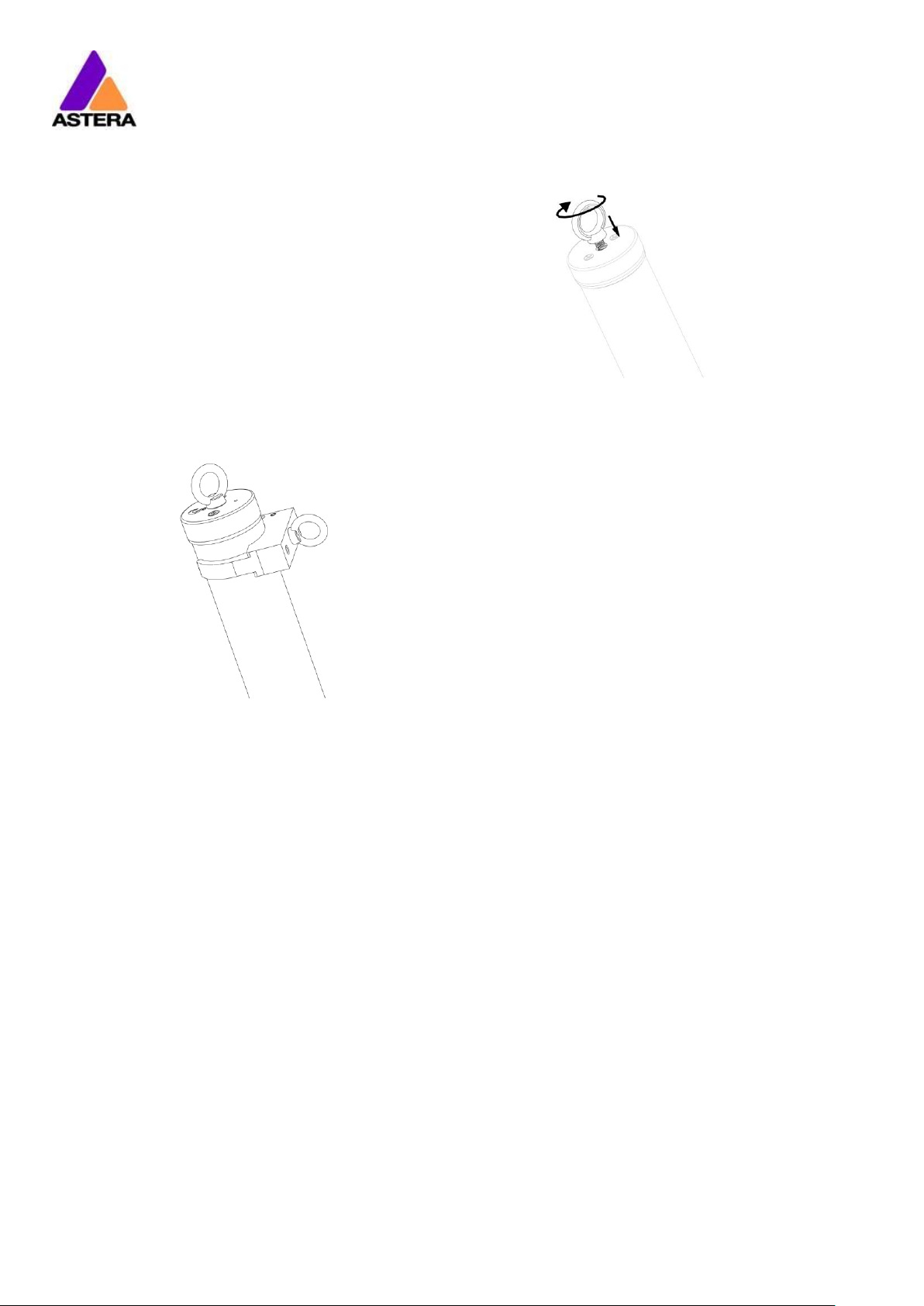
4.1.4 Eyebolts
Eyebolts can be screwed into the M5 threads of the
Titan Tube or the holders. The eye bolts can be used
with a safety wire when hanging a tube via holders
above people’s heads.
The eyebolts can also be used to suspend the tube
but in this case a secondary point must be attached
for safety (e.g. via a holder).

Astera LED Technology GmbH
User Manual for FP1 Titan Tube 2019-01-21
Page | 10
4.2 BATTERY
While running on battery, the light adjusts its output to meet the required minimum runtime. It
can be set by the control panel (see chapter 7.16) or the AsteraApp™ between one and
twenty hours.
The battery is specified to last for 300 full discharge cycles. Its runtime will have decreased to
70% by then. To increase the battery life, it is recommended to recharge as early as possible
and not let the light run until the battery is fully discharged.
If operated below 20°C, the battery runtime may be slightly shorter than predicted. This is also
true if the lights are stored for a long time at cold temperature right before they are used.
The light is constantly monitoring the LED temperature and dims down the brightness if it
exceeds 65°C. That ensures a save and long-live operation but in a hot environment the
brightness might be slightly lower.
PLEASE NOTE: Always store the lights with full battery.
Depleted batteries must be recharged immediately, otherwise their performance will suffer.
ATTENTION: The battery may be only replaced with an original Astera replacement battery.
4.2.1 STANDBY
By using the AsteraApp™, the light can be set to a special standby mode.
In that mode, its output is switched off, the CRMX receiver is powered down and it enters a
state of low power consumption.
A full battery will supply the Titan Tube roughly 20 days in standby mode.
To leave the standby mode press ENTER key or select Leave Standby mode NOW in the
AsteraApp™.
4.3 BATTERY ICON
42%
The display at the backside of the Titan Tube contains a battery icon which indicates the
rough battery status. Next to it is a percentage that shows a more exact battery status.
While the light is connected to AC power, a power plug icon is shown next to the battery
icon. If the battery is fully charged the battery icon will be filled with color and the power plug
icon remains next to the battery icon.
The battery icon is shown in the top navigation and the Main Menu but not in the HIS and
brightness menus. If you do not see the battery icon, press the Menu button once to return to
the top navigation.
Astera LED Technology GmbH
User Manual for FP1 Titan Tube 2019-01-21
Page | 11
4.3.1 HOT icon
During operation with high power in an hot environment the tube might overheat. If this is the
case the output will automatically be reduced until the tube has cooled down enough. A
reduced output is indicated in the display by this icon:
4.4 CHARGING
Charge the light immediately after use and do not store lights with empty battery.
Lights can be charged with individual charger (FP1-CHR) or with Astera’s PowerBox (FP1PWB). If PowerBox and tubes are placed inside a charging case, make sure the case is open.
It is recommended to charge the lights at an ambient temperature between 0°C and 35°C. A
normal charge cycle will take three hours, but may take much longer if the light is hot.
The light is designed to be charged while powered off. If it is connected to AC and powered
on, it may charge at reduced current if enough power is available and the battery
temperature is below 45°C. If the battery temperature is above 45°C, charging stops
completely until the battery has cooled down enough. If the battery temperature cools
below 5°C charging also stops completely until the battery has warmed up enough.
The light has an automatic battery bypass switch, so it can safely be used wired for longer
periods, this will not cause wear to the battery.
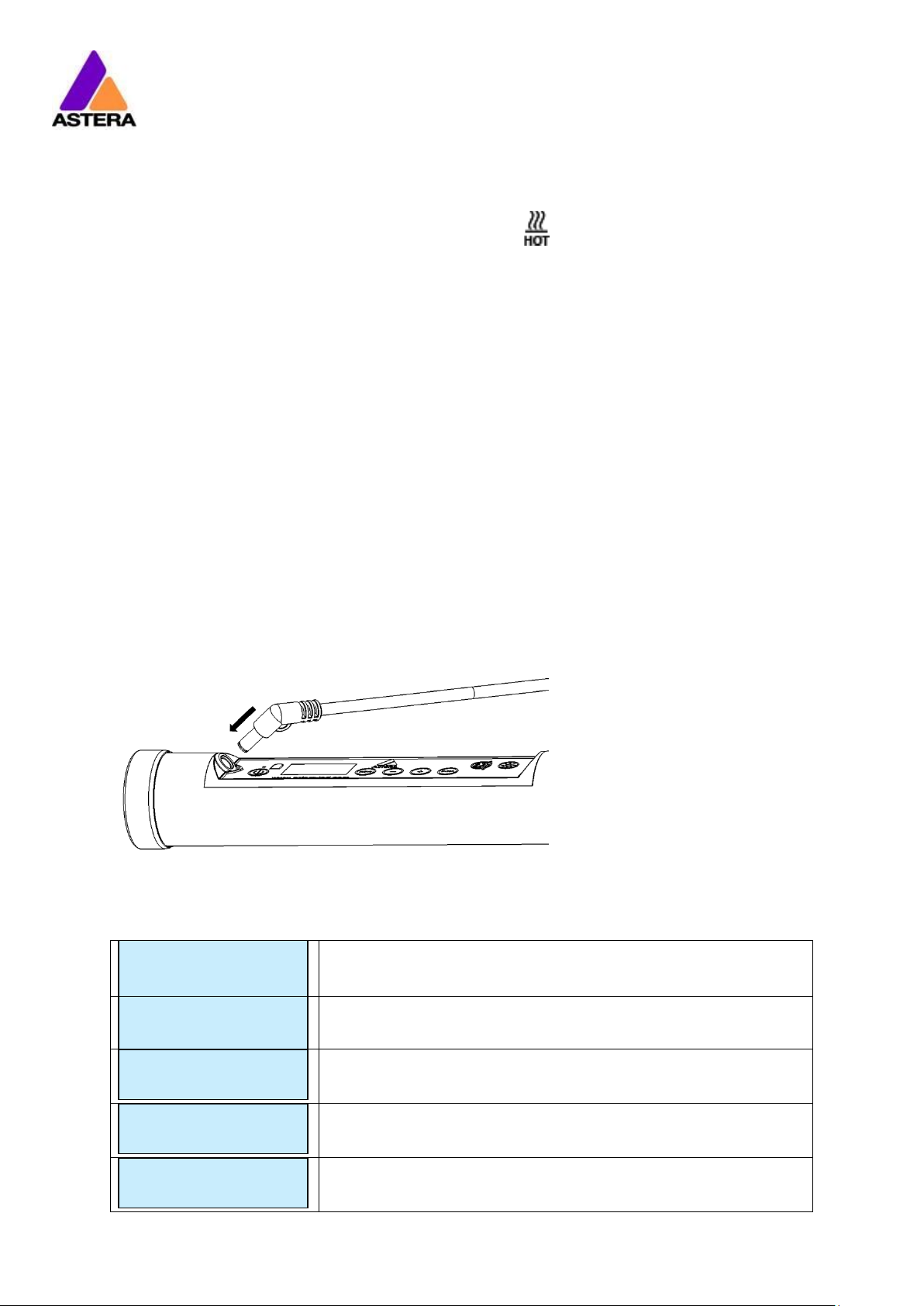
Connecting a cable for charging:
Display messages during charging (only shown when light is powered off):
The battery is being charged.
The battery is fully charged. The LCD backlight will turn off.
The battery cannot be charged, it is too hot. The charger will
start once it has cooled down below 45°C.
The battery cannot be charged, it is too cold. The charger will
start once it has heated up to at least 5°C.
The battery cannot be charged, the error number should be
mentioned to the service.
Charging…
[===== ] 50%
Fully Charged
[===========]100%
TOO HOT: 60°C
[====== ] 50%
TOO COLD:-5°C
[====== ] 50%
ERROR:#5
[====== ] 50%
Astera LED Technology GmbH
User Manual for FP1 Titan Tube 2019-01-21
Page | 12
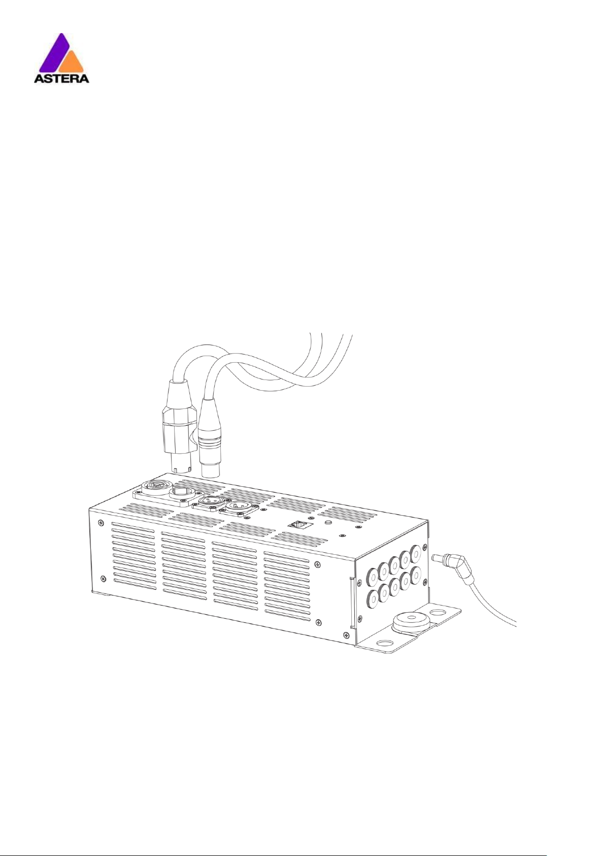
4.5 AC AND DMX WIRING
AC power and DMX data can be connected to the Titan Tube via Astera’s PowerBox (FP1PWB) and Astera’s power/data combination cable (FP1-PWB-CAB). That way, the tubes can
be wired for a longer show or permanent installation.
The PowerBox contains Neutrik True1 Powercon in and out sockets and 5-pin XLR in and out
sockets so that several PowerBoxes can be daisy chained. In addition, data can also be
applied to the PowerBox via its RJ45 Ethernet socket which accepts Art-Net DHCP, 2.X and
10.X as well as sACN. Its operation is explained in the next chapter.
The PowerBox has 10 DC sockets to wire 10 TitanTubes via power/data combination cables
(sold separately, item code: FP1‐PWB‐CAB‐5, -10. -15). 10 output means that a whole DMX
universe of tubes can be connected (10 tubes x 16 pixels x 3 channels).
Power Data
(Powercon True1) (5-pin XLR)
10 x Power/Data
combination cable

Astera LED Technology GmbH
User Manual for FP1 Titan Tube 2019-01-21
Page | 13
4.6 POWERBOX BUTTON AND STATUS LED
The PowerBox contains Powercon True1 in and out sockets as well as XLR in and out sockets.
Also, there is an Ethernet socket which accepts Art-Net (DHCP, 2.X and 10.X) and sACN
4.6.1 Input
The inputs have the following priorities:
1. XLR
2. sACN
3. Art-Net
As long as XLR is received, sACN and Art-Net are deactivated.
While sACN or Art-Net are received, the DMX is also output on the XLR connector.
4.6.2 Status LED
The PowerBox has a status LED next to the Ethernet socket. If the LED is constantly on, this
indicates that no DMX data is being received. If the status LED blinks slowly, this indicates that
the PowerBox receives DMX.
The indicator LED can light up in different colors which indicate which data source is being
received:
Blue
Art-Net DHCP
Magenta
Art-Net 2.X address
Green
Art-Net 10.X address
Yellow
sACN
Cyan
XLR
4.6.3 Button
Next to the indicator LED is a button. A single press on the button cycles between the
different IP settings for Art-Net: DHCP, 2.x and 10.x.
4.6.4 Reset
The controller can be reset to restore the universe ID to 1 again.
Also, during each reset the controller tries to download a software update from the internet.
To be successful, it must be connected to a LAN with DHCP.
The reset is done like this:
Hold the button down -> LED blinks blue -> hold still -> stops blue blinking after 4 sec.
Then the LEDs turn red for a moment and return to Art-Net 2.x again if no update was found.
If an update was found, the LED flashes green/blue until the update has been installed.

Astera LED Technology GmbH
User Manual for FP1 Titan Tube 2019-01-21
Page | 14
4.6.5 To update powerbox software:
1. Connect to a LAN which has an internet access. Be sure that the powerbox is in Art-
Net DHCP mode: blue LED is on.
2. Hold the button down -> LED blinks blue -> hold still -> stops blue blinking after 4 sec.
3. Then the LEDs turn red for a moment. If an update was found, the LED flashes
green/blue until it is done.
4.6.6 To change the universe id manually:
When the powerbox is in the normal mode a long press(4 seconds)* enters the universe
id setting mode. In this mode the blue LED blinks shows the universe id. For example; if the
universe id is 8, the blue LED blinks 8 times then it stops for 2 seconds, this sequence is looped.
A single short press increases the universe id. As the maximum id is 16 in this mode, a single
short press sets to 1 if the universe id is 16. During the universe id setting mode a long press(4
seconds) goes back to normal mode.
* be aware that 8 seconds long press enters the reset mode and restore the universe ID to 1
again.

Astera LED Technology GmbH
User Manual for FP1 Titan Tube 2019-01-21
Page | 15
5 SPECIFICATION
Total LED power:
72W
Maximum power draw:
48W
Illuminants:
Red, Green, Blue, Mint, Amber LEDs
Emittance @1m*:
785 lx
Lumenous Flux*:
2900 lm
Beam Angle:
120°
Field Angle:
180°
CRI*:
96-98 (3200 – 6500 K)
TLCI*:
96-98 (3200 – 6500 K)
Input Voltage:
24 V, 2 A
Battery Runtime:
up to 20hrs (seamless runtime)
Wireless Module:
EU: 868.0-869.7 MHz
US: 902-928 MHz
2.4 GHz
Operating Temperature:
0°C – 40°C
32°F – 104°F
Relative Humidity:
0%-100%
IP Rating:
IP65 (with rubber plug in place)
Dimensions:
Ø42 x 1035mm
Ø1.6” x H40.7”
Weight:
1.35 kg
3.0 lbs
* Typical Values

Astera LED Technology GmbH
User Manual for FP1 Titan Tube 2019-01-21
Page | 16
6 TROUBLESHOOTING
The fixture does not turn on.
The battery may be empty. Connect it to the AC and try again.
A new Titan Tube needs to be connected to AC power for a few seconds to disable its
shipping mode.
The fixture turns on and the display is on, but the LEDs do not emit light.
The fixture could be set to BLACKOUT mode, set to display black color or is operating in DMX
mode and doesn’t receive a valid signal. It is good practice to do a RESET SETTINGS (Chapter
7.22) between setups.
The fixture is not working correctly - it does not display the color or effect chosen.
The fixture may still be operating under a previous setting. It is good practice to do a RESET
SETTINGS (Chapter 7.22) between setups.
After completing a RESET SETTINGS, the fixture still cannot be controlled by AsteraApp™.
Make sure the Radio PIN (Chapter 7.21) of the fixture and AsteraApp™ is the same.
The fixture does not run long enough on battery.
The required RUNTIME can be set. By default, it is set to 5h. To achieve a greater battery
runtime, set the RUNTIME to the required time (Chapter 7.16). Alternatively, program the fixture to only display colors that use less power, such as Red, Green and Blue.
If the runtime is still too short, consider that it is reduced slightly if the battery is very cold.
The power cable is connected but the fixture is not charging.
The battery may be fully charged. Refer to chapter 4.2.1 for more details. The fixture will only
commence charging when its battery has a temperature of 45° or less. Turn the fixture off and
let it cool down; once cold enough, it will start charging. If it still not charging, consult our
website.

Astera LED Technology GmbH
User Manual for FP1 Titan Tube 2019-01-21
Page | 17
7 OPERATION
7.1 SHIP MODE
The Titan Tube is leaving the Astera factory in a special ship mode that allows it to be stored
for a long time without damaging the battery. When using a Titan Tube for the first time,
connect it to AC power for a few seconds to exit the ship mode. Otherwise it cannot be
turned on.
7.2 ASTERARGB COLOR SPACE
The lights work with a specially optimized RGB color space, the AsteraRGB color space. It is
designed to eliminate the need to control each color individually to display a certain color.
Instead, the light calculates the optimum combination of all colors based on an RGB value. It
considers each LED chip’s temperature as well as an optimal color rendering.
Due to this, it is possible to reproduce colors with high accuracy. It is possible to calculate an
AsteraRGB representation for any CIE color. The easiest way to do this is with the AsteraApp™:
Go to the color picker and add a new favorite color
Go to favorite colors and edit it
The dialog on the right will open.
It allows you to find AsteraRGB values for a certain color
temperature. S-RGB or CIE1931 values can be calculated to
AsteraRGB by pressing the corresponding buttons.
The primaries of the AsteraRGB are defined as:
White Point
x
y
0.4917
0.4878
The light also includes the Dynamic Powerboost feature. It ensures that colors that consume
less electrical power are boosted slightly, while power-consuming colors are slightly
compressed. This maximizes the brightness while maintaining the desired battery runtime.
While controlling with the AsteraApp™ or by the Control Panel, only RGB values can be set.
By DMX control, it is possible to control the Amber LEDs separately and also to emulate white
channels. But it should be noted, that then temperature compensation is only available for
Red, Green and Blue; all other colors will experience temperature drift, their brightness will not
be constant.
Red
Green
Blue
xR
yR
xG
yG
xB
yB
0.7079
0.2920
0.1750
0.7200
0.1566
0.0177

Astera LED Technology GmbH
User Manual for FP1 Titan Tube 2019-01-21
Page | 18
7.3 WAYS TO CONTROL
The light can be controlled in several ways:
Use Astera’s ARC1 infrared remote control, point it at individual lights and
press the desired effect. Note that the IR sensor is on the back side next to the
display.
The AsteraApp™ is an efficient way to quickly create a customized light
show. It can group several lights together, address individual lights or groups
of lights, and send complex effects with a user defined color palette to all
lights in range. For additional information refer to chapter 8.
The light can be controlled via DMX or Ethernet cable when connected to
the PowerBox (see chapter 4.5).
The light can also be controlled by wireless DMX, the built-in receiver is
compatible with all LumenRadio* CRMX transmitters as well as W-DMX™* G2,
G3, G4 and G4S transmitters (G4 and G4S in 2.4 GHz mode only).
Power the light on/off, set a static color or change its settings.
*CRMX is a trademark of LumenRadio AB, W-DMX is a trademark of Wireless Solutions Sweden AB
7.4 CONTROL BY INFRARED WITH ARC1
The light can be controlled by the infrared remote control if:
INPUT SELECT is set to AUTO or REMOTE CONTROL (refer to chapter 7.12).
The light is currently NOT operated by DMX. If it is, only ON and OFF will work while
INPUT SELECT is set to AUTO.
The ARC1 is very handy to switch several lights on or off at a time. The ARC1 can also accept
configuration commands that are sent from the AsteraApp™ to a light by pressing the
POWER ON button.

Astera LED Technology GmbH
User Manual for FP1 Titan Tube 2019-01-21
Page | 19
7.5 CONTROL BY THE ASTERAAPP™
Your light has a built in standalone engine. It can display static colors or replay a number of
predefined effect patterns with a customizable color palette.
With the AsteraApp™ these effects can be created and be sent to the light by the built-in
UHF receiver. The effects are just triggered and then each light replays it autonomously until it
receives a new effect.
Lights can be grouped into sets. This way they can be controlled separately and effects can
stretch over up to 128 lights.
Also, you can remotely adjust your lights settings, this eases DMX setup for example.
For more details about the AsteraApp refer to chapter 8.
7.6 CONTROL BY WIRELESS DMX
To pair your light to a CRMX or W-DMX™ transmitter, make sure that:
Your light is not currently paired to a transmitter. To unpair it, refer to chapter 7.17.
INPUT SELECT is either set to AUTO and the light is still in detect mode -or- INPUT SELECT
is set to CRMX wireless DMX; for details refer to chapter 7.12.
Then press the button on your transmitter. After 10 seconds the light should be paired and
show the appropriate status screen (chapter 7.10).
Titan Tubes can also be controlled by Astera’s ART3 Transmitter which was sold from 2009 to
2015. If you prefer to use an Astera ART3 wireless transmitter, set INPUT SELECT to ART3 DMX
and refer to the ART3’s user manual for details.
NOTE:
If you experience difficulties pairing your light, it is recommended to set INPUT SELECT to CRMX
wireless DMX first. This will make sure that the CRMX status screen is displayed.
7.7 CONTROL BY WIRED DMX
The light can be wired to a DMX console. The light itself does not have an XLR socket, the
data connection must be established through the Astera PowerBox (FP1-PWB).
Information about wiring of the PowerBox can be found in chapter 4.5.
If your light does not receive DMX data after being wired correctly, set its Input Select to
Wired DMX (see chapter 7.12).

Astera LED Technology GmbH
User Manual for FP1 Titan Tube 2019-01-21
Page | 20
7.8 CONTROL PANEL
Explanation of the buttons:
When at top Navigation:
When inside Main Menu:
Power on by holding button for 3 seconds
Power off by shortly pressing button
Enter Main Menu
Back to previous Menu
Reset Settings
Scroll down
Change Input Select
Scroll up
Set DMX Address
Choose / Confirm
Adjust color (see chapter 7.23 for details)
Change brightness intensity or runtime (see chapter 7.24 for details)
7.9 BLUE MODE
Blue mode is needed to pair your light with the AsteraApp. To enter Blue Mode, hold down
the POWER button for 3 seconds while the light is switched on. It will start to flicker blue.

Astera LED Technology GmbH
User Manual for FP1 Titan Tube 2019-01-21
Page | 21
7.10 STATUS SCREEN
The status screen is shown after power up. The light also returns to the status screen if no keys
are pressed for three minutes.
It shows:
In the FIRST line what input is currently active
In the SECOND line the current DMX and SET address
INPUT SELECT is set to AUTO and the light did not yet latch to
one input source.
The light is latched to APP CONTROL mode.
INPUT SELECT is set to STANDALONE. The light can no longer be
controlled by any wireless signal.
The light is latched to CRMX mode.
The light is latched to ART3 DMX mode.
Emergency light mode can be active because either AC FAIL
or DMX FAIL being set to EMERGENCY LIGHT.
The standby mode saves power; the light is off and waiting for
a “leave standby” command received by the AsteraApp™.
Theft alarm is active.
If the AsteraApp is asking to “tap a light” and this is shown,
press the ENTER key shortly to accept.
Alternatively you can use an ARC1 infrared remote, aim it at
the light and press POWER ON to accept the setting.
INPUT: DETECTING
SET:001 DMX:001
APP CONTROL
SET:001 DMX:001
STANDALONE
SET:001 DMX:001
CRMX: SIGNAL 99%
SET:001 DMX:001
ART3: NO LINK
SET:001 DMX:001
EMERGENCY LIGHT
SET:001 DMX:001
STANDBY
SET:001 DMX:001
ALARM
DO NOT STEAL THI
ACCEPT CONFIG ?
SET:001 DMX:001

Astera LED Technology GmbH
User Manual for FP1 Titan Tube 2019-01-21
Page | 22
Main menu:
AC FAILURE
Main menu:
INFO
Main menu:
RESET SETTINGS
7.11 MAIN MENU OPTIONS
The main menu can be entered from the status screen by pressing MENU or +. To cycle
between the main menu entries, press the + or – keys. Pressing MENU again will go back to
the status screen.
Used to change the input source or set it to AUTO.
Entering this menu resets all STANDALONE settings to default
and makes the light display a static color.
Set the DMX address.
Set the DMX parameters.
Unpair from a CRMX or W-DMX™ transmitter.
Set the lights runtime on battery in hours.
Set parameters of the standalone engine.
The light can react to the loss of AC power input.
Information about the light: Radio PIN, firmware version, battery
status, ect.
Reset all user settings to default. Should be done after each
usage to ensure consistent behavior. The Radio PIN is NOT reset.
Main menu:
INPUT SELECT
Main menu:
STATIC COLOR
Main menu:
DMX ADDRESS
Main menu:
DMX SETTINGS
Main menu:
UNPAIR CRMX
Main menu:
RUNTIME
Main menu:
STANDALONE

Astera LED Technology GmbH
User Manual for FP1 Titan Tube 2019-01-21
Page | 23
INPUT SELECT
CRMX wirel. DMX
INPUT SELECT
APP CONTROL
7.12 INPUT SELECT
The light accepts several input sources. By default, it is set to AUTO. In this mode, it listens to all
sources, and the first source that becomes active is latched. Once a source is latched, the
light will not listen to any other source anymore.
This latched source is cleared by powering down the light or changing the INPUT SELECT
manually.
Auto mode; the lights waits for
any input signal and latches the
first detected source.
In standalone mode, neither
wireless DMX nor remote control
is accepted.
The light can be controlled by
the AsteraApp™, but any DMX
signal is ignored.
The light can be controlled via
its XLR socket, any wireless
signals are ignored
Only wireless DMX from Astera
ART3 (sold 2009-15) is accepted,
all other sources are ignored.
Only CRMX/W-DMX wireless
DMX is accepted, all other
sources are ignored.
The following table shows what sources are accepted for each setting:
Source INPUT
SELECT
Auto, none latched Auto, Sta
ndalone
latched
Auto, App control
latched
Auto, Astera wirel. DMX latched Autp, CRMX wirel. DMX latched STANDALONE APP CONTROL ART3 DMX
CRMX wirel. DMX Wired DMX
AsteraApp™: change colors
● ● ● AsteraApp™: STANDBY, RUNTIME, ALARM
● ● ● ● ● ● AsteraApp™: DMX Settings
● ● ● ● ● ● ● ● ● ART3 DMX
● ● ● CRMX Wireless DMX
● ● ● ● Wired DMX
● ● ● ● Infrared Remote
● ● ● ● ● ● The Light’s Control Panel
● ● ● ● ● ● ● ● ●
●
Main menu:
INPUT SELECT
INPUT SELECT
AUTO
INPUT SELECT
STANDALONE
INPUT SELECT
ART3 DMX
INPUT SELECT
Wired DMX

Astera LED Technology GmbH
User Manual for FP1 Titan Tube 2019-01-21
Page | 24
HINT:
To avoid the light automatically latching onto CRMX while you want to control it by remote
control, please do UNPAIR CRMX (chapter 7.17). As soon as the remote control is latched, the
CRMX receiver will no longer accept pairing requests.
7.13 SELECT A STATIC COLOR
To make the light show a static color, enter this menu. Immediately when it’s entered, all
previous STANDALONE settings are cleared to default and the INPUT SELECT is latched to
STANDALONE. This is valid until the next power-up only. To make sure the light also shows a
static color after the next power up, set INPUT SELECT to STANDALONE and not AUTO.
You can also change a static color by pressing the color pallet button twice
A number of predefined colors
are available while scrolling
through the menu. See below
for a full table.
In the INDEX COLOR menu, LEE
color gels can be selected. The
list of LEE color gels on page 55.
To set a color by its red, green
and blue value, enter here.
7.13.1 Predefined Colors
Color
Red
Green
Blue
RED
255 0 0
ORANGE
255
107
0
YELLOW
255
160
18
GREEN
0
255
0
CYAN 0 255
224
BLUE 0 0
255
VIOLET
127
84
255
PINK
255
53
119
BLACK 0 0
0
2700K
255
166
70
3200K
255
178
89
4000K
255
193
115
5500K
255
211
150
6500K
255
219
167
Main menu:
STATIC COLOR
Static Color:
RED
Static Color:
6500K
Static Color:
INDEX COLOR
Static Color:
CUSTOM COLOR

Astera LED Technology GmbH
User Manual for FP1 Titan Tube 2019-01-21
Page | 25
7.14 DMX SETTINGS
Several DMX profile tables are
available. Please refer to
chapter 10 for a complete list.
For each of the tables, the
strobe channel can be enabled
or disabled.
Several dimmer curves are
available while the light is
controlled by DMX.
If the DMX signal is lost, the light
can either HOLD the current
output, switch to STANDALONE
operation, to BLACK or
EMERGENCY LIGHT, which
means White 4000K.
7.15 DIMMER CURVE
The dimmer curve sets how the light responds to intensity levels and changes. Most important,
setting the right dimmer curve avoids steppy dimming response.
Several curves are available. By default, the “STANDARD” curve is active.
Name
Intended use
Features
Good compromise
between response and
smoothness
Fits most applications
When slow and smooth
dimming is required
Very smooth response, emulating
a halogen light
For theater stages
Very smooth response and
increased dynamics. Some colors
are darker.
For TV sets and shows
Faster but still smooth dimming.
Less blue light due to white point of
6500K. Less blue light. Increased
dynamics. Some colors are darker.
For Pixel mapping and
similar applications
Totally unfiltered response
Main menu:
DMX SETTINGS
DMX Settings:
DMX TABLE
DMX Settings:
STROBE
DMX Settings:
DIMMER CURVE
DMX Settings:
DMX FAIL
Curve:
STANDARD
Curve:
HALOGEN
Curve:
THEATER
Curve:
TV
Curve:
FAST

Astera LED Technology GmbH
User Manual for FP1 Titan Tube 2019-01-21
Page | 26
7.16 RUNTIME
The light is able to adjust its
power to meet a certain
runtime on battery. The runtime
is always calculated for a full
battery.
EXAMPLE:
If the light is required to light during an eight-hour event, and one hour of setup time is
scheduled, then the runtime should be set to nine hours immediately after the first power up.
NOTE:
Please note, that the light should not be stored below 20°C before an event, otherwise the
runtime might be shorter than calculated.
The runtime feature is always active, even when the light is connected to AC power.
More details on the built-in battery can be found at chapter 4.2.
For additional power-savings refer to the AsteraApp™ manual.
Main menu:
RUNTIME
RUNTIME
1h
RUNTIME
20h

Astera LED Technology GmbH
User Manual for FP1 Titan Tube 2019-01-21
Page | 27
7.17 UNPAIR CRMX
Once your light is paired to a CRMX or W-DMX™ transmitter, it cannot be paired to another
one until it is unpaired. This can be either done by using the button on the transmitter that is
currently paired or on the light directly.
If you wish to unpair your CRMX wireless DMX receiver from a Lumen Radio or W-DMX™
transmitter, go to UNPAIR CRMX and press enter.
NOTE:
The CRMX receiver is only powered while INPUT SELECT is:
set to CRMX wireless DMX
or AUTO and either CRMX is latched or no source is latched yet.
For details in INPUT SELECT refer to chapter 7.12.
Main menu:
UNPAIR CRMX

Astera LED Technology GmbH
User Manual for FP1 Titan Tube 2019-01-21
Page | 28
7.18 STANDALONE
Select one of the predefined
patterns, see table below.
Sets the dimmer level.
The time that one cycle of the
program takes to complete.
The fade behavior between
each step of the program.
0% means, no fading
100% means full fading, fade-is
directly followed by fade-out.
The color palette of the
programs consists of up to four
colors. They can be set
individually. See chapter 7.13 for
details on how to set a color.
Main menu:
STANDALONE
Standalone:
PROGRAM
Standalone:
INTENSITY
Standalone:
SPEED
Standalone:
FADE
Standalone:
COLOR C1
Standalone:
COLOR C4

Astera LED Technology GmbH
User Manual for FP1 Titan Tube 2019-01-21
Page | 29
7.18.1 Predefined Programs
The predefined programs may use more than one pixel. To display these effects properly with
your light, it is first necessary to group them into Flow-Sets and control them by the
AsteraApp™ (see chapter 8.4).
If several lights are grouped into a Flow-Set, they form a virtual big light with several pixels.
Name
Pattern
ONE COLOR STATIC
A static color is displayed on the whole virtual light.
TWO COLOR STATIC
The virtual light is split into two halfs and two colors are displayed.
THREE COLOR STATIC
The virtual light is split into three parts and three colors are displayed.
FOUR COLOR STATIC
The virtual light is split into four parts and four colors are displayed.
ONE COLOR FADE
For all FADE programs, the whole color palette of four colors is used. Those
colors are faded in and out one by one.
Here, the whole virtual light shows the same color.
TWO COLOR FADE
The virtual light is split and shows two colors at a time.
THREE COLOR FADE
The virtual light is split and shows three colors at a time.
FOUR COLOR FADE
The virtual light is split and shows four colors at a time.
SIMPLE RUNNING
A running light; the background and the running pixels color can be set.
DOUBLE RUNNING
Two pixels are running in opposite direction.
TWO COL RUNNING
The two pixels are of different color even.
FLAG RUNNING
A three color flag is running over the background color.
DOUBLE FLAG RUNNING
Two flags are running over background in opposite direction.
SPIRAL 4 COLORS
The color is changed pixel by pixel. All four colors are used one after the
other.
SPIRAL 2 COLORS
The color changes between color 1 and 2 from the outside to the inside,
pixel by pixel.
RAINBOW
A rainbow effect is displayed.
FIRE
The fire effect is a random flicker between two colors, background and
flickering color.
NOTE:
It is highly recommended to check out the effects editor of the AsteraApp™ to get a better
understanding of how those programs work. Also, many programs look similar if the lamp is
NOT grouped into a Flow-Set.

Astera LED Technology GmbH
User Manual for FP1 Titan Tube 2019-01-21
Page | 30
7.19 AC FAILURE(EMERGENCY LIGHT)
The light can react to the loss of AC power in several ways. As soon as AC is present again,
the light resumes normal operation.
No special behavior on AC loss.
The light will turn dark if AC is
lost.
The light will switch to a 4000K
white as soon as the AC is lost.
7.20 DMX FAILURE
When in CRMX Wireless DMX mode, XLR DMX mode or ART3 DMX mode the light can react to
the loss of a DMX signal in several ways. As soon as a DMX signal is present again, the light
resumes normal operation.
The last received DMX Frame is
displayed
The light will switch to a 4000K
white as soon as the AC is lost.
The light will switch to black, no
light will be visible.
Main menu:
AC FAILURE
AC FAILURE
NO ACTION
AC FAILURE
BLACKOUT
AC FAILURE
EMERGENCY LIGHT
DMX settings:
DMX Fail
DMX FAIL
HOLD
DMX FAIL
EMERGENCY LIGHT
AC FAILURE
BLACKOUT

Astera LED Technology GmbH
User Manual for FP1 Titan Tube 2019-01-21
Page | 31
7.21 INFO
Set the Radio PIN. To change
the PIN, press ENTER. Adjust
each digit with the + and – keys,
cycle through the digits with the
MENU key. When finished, press
ENTER again.
Enable to match color and
brightness of your Titan Tube to
AX1 Pixeltubes so that they can
be used side by side.
Tells the serial number of the
light and the CPU type (43xx).
The firmware version and
hardware version of the light.
The hour-counter is counting up
as long as the light is powered
up. It does not count if the light
is powered off and charging.
While the light is receiving an
UHF signal, this tells the signal
strength and deviation.
Shows the firmware of the builtin LumenRadio CRMX chip
The current charging state of
the battery in percent.
Shows how many battery cycles
the built-in battery has passed
already
Gives information about the LED
calibration stored in the light, for
service reference only.
7.22 RESET SETTINGS
Return the light to the default
settings. This may be done
before each use to start from a
known point. The Radio PIN and
the CRMX pairing stay.
HINT
It is highly recommended to reset the light’s settings after each event to ensure a clear start
for the next usage.
Main menu:
INFO
Radio PIN:
0000
Serial number:
000-00000 43xx
Firmware version
5.2.20.U HW001
RF link:
-36.0dBm -0.0ppm
Battery state:
100%
Calibration:
2015-04-20-0001
Main menu:
RESET SETTINGS
ARE YOU SURE?
NO YES
CRMX Version:
V1.0.5.0
Battery Cycles:
003
AX1 Compatibility
ENABLED
Power-on hours:
00001h

Astera LED Technology GmbH
User Manual for FP1 Titan Tube 2019-01-21
Page | 32
7.23 ADJUST COLOR VIA THE COLOR PALETTE BUTTON
The color palette button on the Titan Tubes’s keyfoil offers the possibility to adjust the color of
the tube in several ways.
If the Color Palette button is pressed once it will show the HSI screen shown blow. To jump
between lines, press the Enter button. To edit a value, press + or – button.
Color Temperature is selected.
You can set the color temperature of your tube from 1,750 to
20,000 Kelvin.
Green / Magenta Correction is selected.
You can adjust the displayed color by adding or subtracting
the amount of green to reduce post-production work.
This is designed for white tones, not for colors.
Hue is selected.
Set a hue (color appearance) from 0 to 360
Saturation is selected.
You can adjust how much of the selected Hue you want to
mix to the selected Color Temperature.
Press the Color Palette button a second time to reach the static color screen shown below.
Press + or – buttons to select a basic static color
Press the Color Palette button a third time to reach the filter gel screen shown below. To jump
between the second and third line, press the Enter button. To edit a value, press + or – button.
Change between gel types.
You can change between Lee* filters with daylight or
tungsten lightsource and Rosco* filters with daylight or
tungsten lightsource.
Change between gel numbers
Browse through gels. The selected line shows their number
while the line below shows the corresponding gel name.
Once the Color Palette button is pressed the selected values will be displayed on your tube
immediately. Input Select will be changed to Standalone. If the Input Select was set to
anything other than Auto or Standalone, pressing the Color Palette Button has no effect.
*LEE is a registered trademark of Panavision International, L.P.
*Rosco is a registered trademark of Rosco Laboratories, Inc
CCT : 1750 K_
Green : 0.00
Hue : 360
Sat : 100%
CCT : 1750 K
Green : 0.00_____
Hue : 360
Sat : 100%
CCT : 1750 K
Green : 0.00
Hue : 360______
Sat : 100%
CCT : 1750 K
Green : 0.00
Hue : 360
Sat : 100%_____
Static Color:
Red______________
Color Gel:
Lee Daylight_____
071
Tokyo Blue
Color Gel:
Lee Daylight
071______________
Tokyo Blue

Astera LED Technology GmbH
User Manual for FP1 Titan Tube 2019-01-21
Page | 33
7.24 ADJUST BRIGHTNESS OR RUNTIME VIA THE BRIGHTNESS BUTTON
The brightness button on the Titan Tube’s keyfoil offers the possibility to quickly adjust the
brightness or runtime of the tube.
Once the Brightness button is pressed it will show the below screens. To jump between lines,
press the Enter button. To edit a value, press + or – button.
Brightness is selected.
Set the total brightness of this tube from 0% to 100%.
Runtime is selected.
Change the seamless runtime of the tube from maximum
brightness up to 20h. Additional information about runtime
can be found in chapter 7.16.
Once the Brightness button is pressed the selected values will be displayed on your tube
immediately. Input Select will be changed to Standalone. If the Input Select was set to
anything other than Auto or Standalone, pressing the Color Palette Button has no effect.
Brigntness: 100%_
Runtime: 5h
Brigntness: 100%
Runtime: 5h__

Astera LED Technology GmbH
User Manual for FP1 Titan Tube 2019-01-21
Page | 34
8 USING THE LIGHT WITH THE ASTERAAPP™
The buttons of the Titan Tube allow a basic operation of the light. To gain full control over all
features, the AsteraApp™ should be used.
The AsteraApp™ is an efficient way to quickly create a customized light show. It can group
several lights together, address individual lights or groups of lights, and send complex effects
with a user defined color palette to all lights in range.
Additionally, it can be used to adjust the lights settings remotely.
The AsteraBox™ is needed to interface your Android device with the lights. It communicates
to the Android or iOS device by Bluetooth and controls the lights by UHF.
8.1 PAIR YOUR LIGHT WITH THE ASTERAAPP™
The connection is secured by a 4 digit Radio PIN. Only if the
lights PIN matches the AsteraApp™ PIN, lights are controllable.
The pairing process transmits the radio pin from the app to the
light and stores it there.
1. Choose a unique Radio PIN in the app.
2. Switch the light into blue mode, see chapter 7.9.
3. Press the “Pair with Lights” button in the AsteraApp™.
NOTE:
Alternatively, you can set the Radio PIN manually at the Control Panel of the light. Refer to
chapter 7.21 for details.

Astera LED Technology GmbH
User Manual for FP1 Titan Tube 2019-01-21
Page | 35
8.2 POWERFUL LIGHT CONTROL
Your light has a built in standalone engine. It can display static colors or replay a number of
predefined effect patterns with a customizable color palette.
With the AsteraApp™ these effects can be created and be sent to the light by the built-in
UHF receiver. The effects are just triggered and then each light replays them autonomously
until a new effect is sent.
Lights can be grouped into sets. This way they can be controlled separately and also effects
can stretch over up to 32 lights.
8.3 CHANGE THE COLOR
On the AsteraApp™ main
screen, press “Just Red”.
Once in the editor, press
“C1”.
Now the lights color can be
changed.
The “123” button offers
common color gels. Hit the
sort button to sort by color or
number (1).
To add a color to the
favorites, press (2).
To edit an existing favorite
color, select it and press the
pen (1).
The editor will open. RGB
values can be adjusted
directly. Also a color
temperature can be
converted to RGB.

Astera LED Technology GmbH
User Manual for FP1 Titan Tube 2019-01-21
Page | 36
8.4 CREATE A SET
Before the more powerful effects can be reviewed, it is recommended to create a Flow-Set
first.
Each light can be assigned to one set. Two types of sets are available:
8.4.1 SYNC SET
All lights that are assigned to a Sync-Set can be controlled together. They
will do exactly the same.
CREATE A SYNC-SET:
On the AsteraApp™ main
screen, first press the Targets
button (1) and then the “+”
sign (2) to add a new target.
Choose “Sync-Set”.
Now all lights will flicker
every two seconds. Tap the
Enter button of your light to
add it to the set.
Additionally, the name of
the set can be customized.
When finished, press the
save button.

Astera LED Technology GmbH
User Manual for FP1 Titan Tube 2019-01-21
Page | 37
8.4.2 FLOW SET
By using a Flow-Set, lights can also be controlled together. But additionally,
they are assigned to positions inside the Flow-Set and so form a virtual light
with several pixels. All effects, like a running light, are stretched over this
virtual light.
CREAT A FLOW-SET:
On the AsteraApp™ main
screen, first press the Targets
button (1) and then the “+”
sign (2) to add a new target.
Then choose “Flow-Set”.
Each flow set can have up
to 32 positions. Once the
correct number is entered,
press “Confirm”.
Now your lights will flicker
every two seconds. To add a
light to the currently shown
positon of this set, press its
button. Walk through the
positions by “Previous” and
“Next” and assign your lights.
When finished, press the
save button on top.
8.5 TARGETING LIGHTS
Once you have created a set, you may now choose to control it. By
default “All lights” are targeted. That includes all sets.
It is possible to target more than one set at a time.
NOTE:
Even while targeting „All Lights” the Flow-Sets position arrangements
persist. The lights still form a virtual big light of several positions.
To modify, delete or arrange targets, use the pen button (1).

Astera LED Technology GmbH
User Manual for FP1 Titan Tube 2019-01-21
Page | 38
8.6 CHANGING THE EFFECT
On the AsteraApp™ main
screen, press “Wedding” (1),
then enter the editor (2).
Set “Crossfade” to 0% and
“Speed” to around 2
seconds. You should see a
clean running light now. The
White light will run over a
pink background.
The effect can be changed
by sliding the effect picker
and choosing a sub-effect
below it. Again the colors
can be adjusted, too.
After the effect is adjusted, it may be saved back to the main screen by pressing the save
button.
AN EFFECT CAN BE HIGHLY CUSTOMIZED:
The speed tells how long it will take for the effect to complete one cycle.
The crossfade tells if the light will fade from step to step. If it is set to 0% an immediate change
is visible. If set to 100% the changes will be soft.
Stroboscope effect can be enabled and seamlessly adjusted in speed. Additionally, three
random stroboscope options are available: slow, medium and fast.
Each effect can be adjusted in brightness as well.

Astera LED Technology GmbH
User Manual for FP1 Titan Tube 2019-01-21
Page | 39
8.7 LIST OF EFFECTS
The effects’ patterns are pre-defined and cannot be modified by the user. They are preprogrammed inside of each light. Still they can be parameterized. These effects are:
A static color is displayed. There are also options that show two, three or four
static colors at a time. The Flow-Set is then divided into several parts of equal
length:
Fading colors. The four defined colors are displayed one after the other. The
setup fade is applied between them. Again, the Flow-Set can be split in up
to four segments.
From both sides of a Flow-Set, the color changes position by position from C1
to C2. Once the whole Set is C2, it changes back to C1 in the same way.
The color of the Flow-Set changes position by position. After all positions
show the same color, a new cycle is started.
Several variations of running lights are available.
The Fire effect shows a random flickering effect. The background color and
the color of the flickering effect can be adjusted.
The rainbow effect shows a color change through all colors. Only its speed
can be adjusted.
Chaser effects provide an efficient means to create dancefloor lighting. The
static chaser exchanges the color of the lights according to the tapped-in
beat. The colors are randomly chosen. The effect can be adjusted to show
up to 4 different colors at a time.
The Moving Chasers overlay the static chaser by a second movement of the
four displayed colors over the available positions of a Flow-Set. This gets
mostly interesting of the Moving Strobe is chosen. Then, only some of the
positions strobe and they are moving. So the strobe effect moves over the
Flow-Set.
When using the Chaser With Background, additionally a color can be
selected that is mostly used, the background color.

Astera LED Technology GmbH
User Manual for FP1 Titan Tube 2019-01-21
Page | 40
8.8 CHASER EFFECTS IN DEPTH
To display chaser effects, it is recommended to setup a Flow-Set with a multiple of four
positions. This is the way they will be shown best. Those four positions could then be arranged
in the corners of a dance floor for example.
Use the tap-sync button to tap the beat of the music; the Chaser Effects will base their color
changing on that beat then.
The Chaser Effects offer additional controls
The Emphasis adjusts the way the colors are exchanged by the chaser:
Emphasis
Effect
-2
The four colors of the palette are exchanged one by one. Every beat changes
only one color.
-1
Same as “-2”, but the color change is animated with the color-wheel effect; it
mimics the color change of a traditional color wheel, showing intermediate
colors during the change.
0
All four colors are exchanged on every beat.
1
Same as “0”, but the color wheel effect is added.
2
Same as “0”, but on the fourth beat, all colors go black. They come on again
on the next beat.
3
Same as “0”, but all colors go black on every second beat. This setting
produces a strong on-off effect in sync with the beat.
The softness influences the fading between colors that happens on every beat. 0% will
generate a hard change of the colors, while 100% makes them fade very slowly.
A random button is added to the color bar. If it is latched, random colors are chosen on
every beat. If not (like in the above picture), then the colors are always chosen randomly
from the color pallet of four. This is useful to intentionally narrow down the color choice. Nice
effect can be generated by setting some of them to black.

Astera LED Technology GmbH
User Manual for FP1 Titan Tube 2019-01-21
Page | 41
8.9 THE MAIN SCREEN
Here each program is represented by a tile. Those tiles can be edited and freely positioned.
Several pages of tiles are available.
To move or delete a tile,
press the pen icon (2). A
popup will show the
available actions.
To add a new program tile,
press the “+” icon (1).
While adding a tile, either a
default “Static Red” or the
currently running program
can be selected.
Additionally, special function
tiles are available.
8.9.1 Function Tiles
Tapping this tile several times to the beat will let the Chaser Effects
change their colors to the beat. A chaser effect has a dancer symbol
on the tile.
This button can be used to quickly blackout lights. The currently set target
must be observed, as the blackout function will only affect the currently
targeted lights.

Astera LED Technology GmbH
User Manual for FP1 Titan Tube 2019-01-21
Page | 42
8.10 BRIGHTNESS
Additionally to each programs brightness slider mentioned in chapter 8.6, a master brightness
control is available.
As soon as more than one Set is created
and at least one set is currently
targeted, a sub-master for each Set is
shown.
Otherwise, only one slider is available. It
controls the brightness of all currently
targeted lights.
8.10.1 Set Sub-Masters
Each Set has its own brightness slider. Additionally, there is a master slider that controls the
brightness of all Sets simultaneously. This is very similar to the group brightness control of
common lighting desks.
NOTE:
The Set-Masters are only shown if:
a) More than one Set has been created before
b) Only Set-Targets are currently selected. Selecting any other type of target, like “All
Lights” will hide the Set-Masters. This is necessary to avoid that one lights gets
redundant brightness information; it would flicker constantly between different
brightness levels.

Astera LED Technology GmbH
User Manual for FP1 Titan Tube 2019-01-21
Page | 43
8.11 RUNTIME
The light is able to adjust its power to meet a certain runtime on
battery. The runtime is always calculated for a full battery.
Example:
If the light is required to light during an eight hour event,
and one hour of setup time is scheduled, then the
runtime should be set to nine hours immediately after the
first power up.
Please note, that the light should not be stored below 20°C
before an event, otherwise the runtime might be shorter than
calculated.
More details on the built-in battery can be found at chapter 4.2.
8.12 ANTI-FLICKER
The AsteraApp has an Anti-Flicker function where the PWM rate of spotlights (AX3/5/7/10) can
be adjusted. For the Titan Tube this feature does not have any effect. The Titan Tube operates
on a scrambled PWM rate which does not cause flicker effects when being filmed.

Astera LED Technology GmbH
User Manual for FP1 Titan Tube 2019-01-21
Page | 44
8.13 THEFT ALARM
Your light is equipped with a theft alarm. A motion sensor in the light detects when it is
moved/taken away and a small siren will sound to deter potential thieves.
First make sure your Radio
PIN is different from 0000.
See chapter 8.1 how to
change it. Then press the
“ON” button.
Press “Activate”. All targeted
lights will flash shortly to
indicate that they are now
armed.
If the siren is set to DELAYED, it sounds only if the
alarm persists for more than 6 seconds. The ON
setting makes it sound immediately, while the OFF
setting mutes it always.
The sensitivity can be adjusted to meet your
environment. A lower value makes a false alarm
more unlikely.
In case a potential thief is taking the light away while
ignoring the alarm, he will most likely cause alarm
events for more than 2 minutes in a row. In that case,
the alarm can be set to become permanent. Then it
won’t stop, even if the light is placed down again. It
will run until the battery is empty, rendering the light
useless for the thief.
In some applications it is not desirable to have the
lights flashing while the alarm is enabled or disabled.
It can be disabled by this option easily.
The alarm can be silenced without turning it off by
pressing this button.
NOTE:
To turn the alarm off again, an AsteraApp™ with the same Radio PIN must be used. Do not
forget your Radio PIN! Otherwise, your light cannot be used normally anymore.

Astera LED Technology GmbH
User Manual for FP1 Titan Tube 2019-01-21
Page | 45
8.14 ENTER AND LEAVE STANDBY
The standby is intended to be used between setup and event (see chapter 4.2.1). After setup
is completed, all lights may be switched to standby mode and woken up later when the
event starts. This ensures that no battery runtime is wasted. This can be either done manually
or automated.
Press the small arrow to
open the standby menu.
By pressing the “Now”
buttons, standby can be
switched on or off for all
currently targeted lights.
Any of the “Later” buttons
will require a time to be set.
The standby will be
scheduled to the specified
time.
NOTE:
While you are using the “Now” function, only those lights that are currently targeted are
addressed (see chapter 8.5 how to target lights).
The “Later” function always sends to the “All Lights” target!

Astera LED Technology GmbH
User Manual for FP1 Titan Tube 2019-01-21
Page | 46
8.15 DMX SETTINGS
In order to efficiently use the light with DMX, some setting can be adjusted by the
AsteraApp™.
Press the “DMX
Configuration” button.
Adjust all settings to your
requirements, then press
“Send”.
Your lights will start to flicker.
Tap the lights you wish to
setup (chapter 7.10). Then
press “Done”.
Please refer to chapter 7.12, Input Select, and chapter 7.14, DMX Settings, for details on the
available settings.
8.15.1 DMX Channel Assignment
The current channel assignment can be always reviewed in
the lower part of the screen. It is automatically calculated
based on the setting of Table and Strobe.
 Loading...