

AX5
TriplePAR™
User Manual

Astera LED Technology GmbH
User Manual for AX5 TriplePAR™ 2017-09-08
Page | 1
1 CONTENTS
2 Package Contents .............................................................................................................................................. 3
3 Safety and Handling ............................................................................................................................................ 3
3.1 Bracket .......................................................................................................................................................... 4
3.2 Hanging The AX5 ......................................................................................................................................... 6
3.3 Kickstand ...................................................................................................................................................... 8
3.4 Filter................................................................................................................................................................ 9
3.5 Battery ......................................................................................................................................................... 10
3.6 Battery Icon and Status LED .................................................................................................................... 11
3.7 Charging ..................................................................................................................................................... 11
3.8 Charging Case .......................................................................................................................................... 12
3.9 AC Wiring .................................................................................................................................................... 13
4 Specification ....................................................................................................................................................... 14
5 Troubleshooting .................................................................................................................................................. 14
6 Operation ............................................................................................................................................................ 15
6.1 AsteraRGB Color Space ........................................................................................................................... 15
6.2 Ways to Control ......................................................................................................................................... 16
6.3 Control By Infrared with ARC1 ................................................................................................................ 16
6.4 Control by the AsteraApp™ ................................................................................................................... 17
6.5 Control by Wireless DMX .......................................................................................................................... 17
6.6 Control by wired DMX .............................................................................................................................. 17
6.7 Control Panel ............................................................................................................................................. 18
6.8 Status Screen ............................................................................................................................................. 18
6.9 Main Menu Options .................................................................................................................................. 19
6.10 Menu Shortcuts .......................................................................................................................................... 19
6.11 INPUT SELECT .............................................................................................................................................. 20
6.12 Select a Static Color ................................................................................................................................. 21
6.13 DMX Settings .............................................................................................................................................. 22
6.14 DIMMER CURVE ......................................................................................................................................... 26
6.15 DMX FAIL ..................................................................................................................................................... 26
6.16 RUNTIME ...................................................................................................................................................... 27
6.17 UNPAIR CRMX ............................................................................................................................................ 28
6.18 STANDALONE ............................................................................................................................................. 29
6.19 AC FAILURE (EMERGENCY LIGHT) ........................................................................................................... 30
6.20 INFO ............................................................................................................................................................. 31
6.21 RESET SETTINGS ........................................................................................................................................... 31
7 Using the Light with the AsteraApp™ ............................................................................................................. 32
7.1 Pair your Light with the AsteraApp™ ..................................................................................................... 32
7.2 Powerful Light Control .............................................................................................................................. 33
7.3 Change the Color ..................................................................................................................................... 33
7.4 Create a Set ............................................................................................................................................... 34
7.5 Targeting Lights.......................................................................................................................................... 35
7.6 Changing The Effect................................................................................................................................. 36
7.7 List of Effects ............................................................................................................................................... 37
7.8 Chaser Effects in Deep ............................................................................................................................ 38
7.9 The Main Screen ........................................................................................................................................ 39
7.10 Brightness .................................................................................................................................................... 40
7.11 RUNTIME ...................................................................................................................................................... 41
7.12 Anti-Flicker .................................................................................................................................................. 41
7.13 Theft Alarm ................................................................................................................................................. 42
7.14 Enter and Leave Standby ........................................................................................................................ 43
7.15 DMX Settings .............................................................................................................................................. 44
8 Menu Overview .................................................................................................................................................. 45
9 Attachements ..................................................................................................................................................... 46
10 Version History ..................................................................................................................................................... 48

Astera LED Technology GmbH
User Manual for AX5 TriplePAR™ 2017-09-08
Page | 2
This instruction manual is part of the device and persons operating the device must have
access to it at any time.
Safety precautions mentioned in the instruction manual have to be observed.
If the device is being sold, this instruction manual has to be included.
This manual is valid for lights with firmware version 5.6.6 and up.
Translations
If the device is being sold, this instruction manual has to be translated into the national
language of the destination country.
If discrepancies occur in the translated text, the original instruction manual has to be used to
solve them for the manufacturer has to be contacted.
Contact Information
Astera LED Technology GmbH
Stahlgruberring 36
81829 Munich
Germany
+49 89 2155253-0
Technical support
Europe: +49 89 21552253-1
USA: +1 954 578 8881
Asia: +86 755 28237295
Email: service@astera-led.com
©2017, Astera LED Technology GmbH
All rights reserved
Astera LED Technology GmbH
User Manual for AX5 TriplePAR™ 2017-09-08
Page | 3
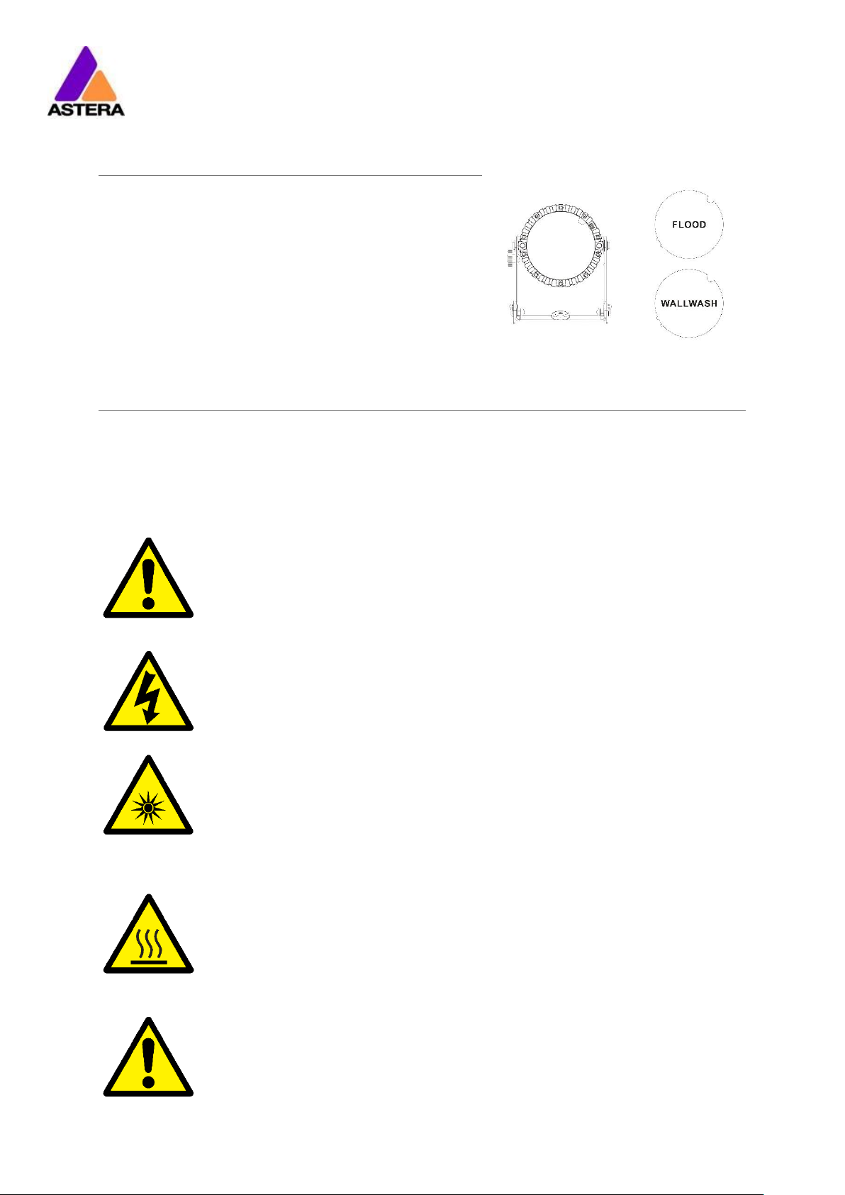
2 PACKAGE CONTENTS
• TriplePAR™
• Filter FLOOD
• Filter WALLWASH
• Quick Start Guide
3 SAFETY AND HANDLING
Before you operate this unit read the manual carefully. Always make sure to include the
manual if you pass/rent/sell the unit to another user. Keep in mind that this manual cannot
address all possible dangers and environments. Please use your own caution when
operating. This product is for professional use only. It is not for household use.
• Do not operate the unit in areas of high temperature conditions or
under direct sunlight. It will cause abnormal function or damage the
product.
• Always use a suitable safety wire when mounting the light
overhead.
• Connect the safety wire only to the intended safety mount.
• Always follow local safety requirements.
• Only qualified personnel may repair this product.
• Do not open the product housing.
• Do not apply power if the light is damaged.
• Do not submerge the light into any liquid.
• Do not directly look into the light.
• It can cause harm to your eyes.
• Do not look at the LEDs with a magnifying glass or any other optical
instrument that may concentrate the light output.
• Use only Astera approved accessories to diffuse or modify the light
beam.
• The exterior surfaces of the light can become hot, up to 70°C
(158°F) during normal operation.
• Ensure that accidental physical contact with the device is
impossible.
• Install only in ventilated locations.
• Do not cover the light.
• Allow all lights to cool before touching.
• Keep 0.3m (12in) from objects to be illuminated.
LI-ION Battery: A rechargeable lithium ion battery is built into this unit.
• Only authorized personal may service the battery.
• Do not place in fire or heat.
• Do not use or charge the light if it is damaged.
• Avoid bumping or plunging, it may cause fire or explosion.
Astera LED Technology GmbH
User Manual for AX5 TriplePAR™ 2017-09-08
Page | 4
• Never store the battery when fully drained.
• Always recharge immediately when empty.
• Make sure to fully charge all units before storing them.
• Partially charged batteries will lose capacity.
• Fully recharge every 6 months if not used.
• The battery may only be replaced with an original spare part from
Astera.
• Follow applicable laws and regulations for transport, shipping, and
disposal of batteries. For details on recycling lithium, lithiumphosphate, and lithium-ion batteries, please contact a government
recycling agency or your waste-disposal service.
• Always charge with the flight case open.
• It is recommended to charge at a temperature between 15°C and
35°C
• The light contains a lithium ion battery.
• Don't throw the unit into the garbage at the end of its lifetime.
• Make sure to dispose is according to your local ordinances and/or
regulations, to avoid polluting the environment!
• The packaging is recyclable and can be disposed.
3.1 BRACKET
FOLDABLE BRACKET:
Astera LED Technology GmbH
User Manual for AX5 TriplePAR™ 2017-09-08
Page | 5
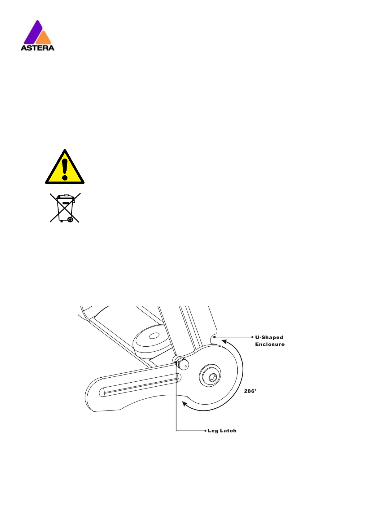
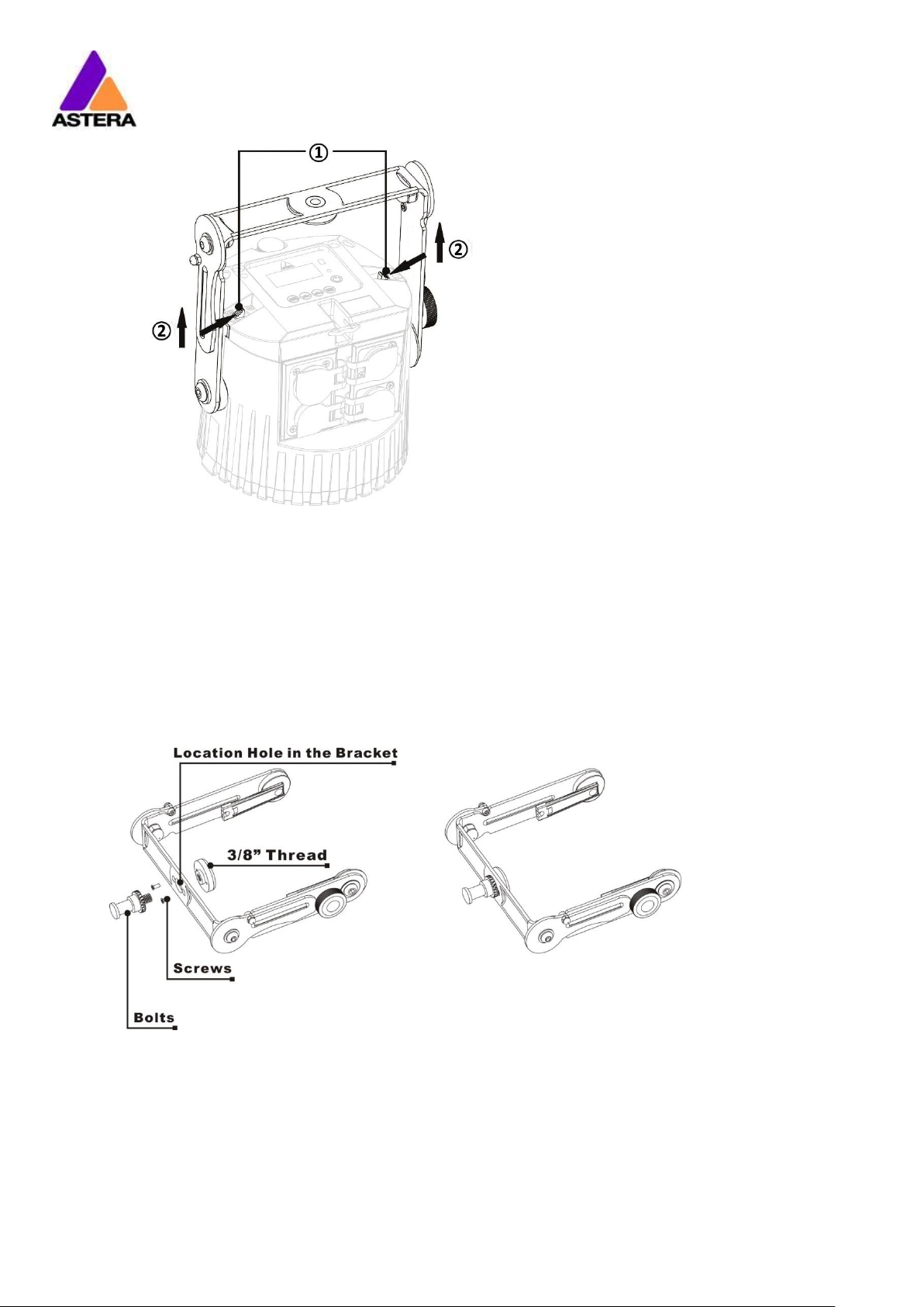
The AX5 TriplePAR™ is fitted with a foldable bracket. This is beneficial for
storage, transportation and charging because the legs fold parallel to each
other. The ergonomic handle also allows easy carrying.
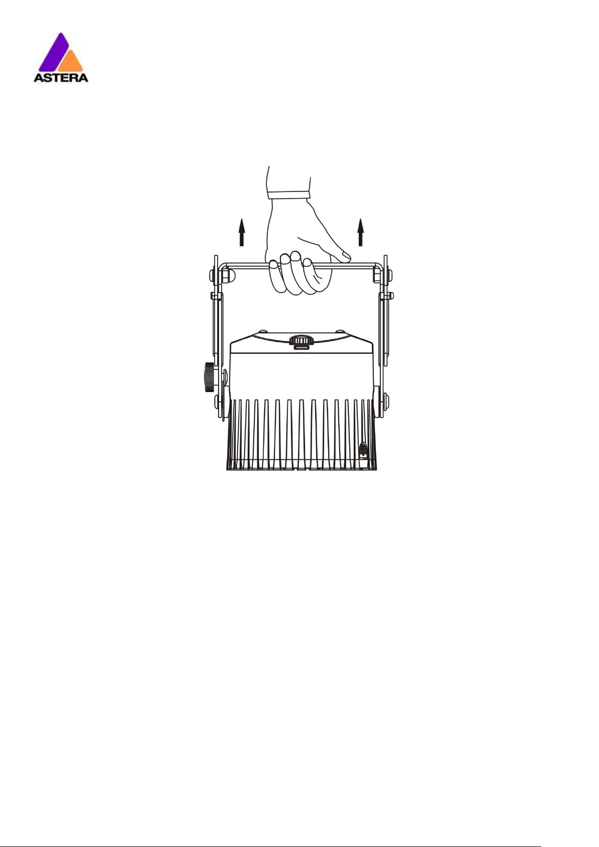
REMOVING THE BRACKET:
STEP 1: Push the bracket-lock sliders inwards.
STEP 2: Slide the bracket upwards.
Astera LED Technology GmbH
User Manual for AX5 TriplePAR™ 2017-09-08
Page | 6
3.2 HANGING THE AX5
THE THREAD AND BOLT:
The thread fixing and bolt are for hanging the AX5. The thread fixing is 3/8”
and it can be removed by removing the 2 screws to fit other clamps. The
location hole in the bracket is 14.2mm. This 3/8” thread fitting works with the
same bolt that is used to hang AX1 and AX3 Lamps.

Astera LED Technology GmbH
User Manual for AX5 TriplePAR™ 2017-09-08
Page | 7
SAFETY WIRE AND CARABINER:
When hanging the AX5 it is to be secured with a safety wire and carabiner,
each able to hold at least 40kg. Make sure the light cannot drop more that
20cm in case the primary mounting fails.
Astera LED Technology GmbH
User Manual for AX5 TriplePAR™ 2017-09-08
Page | 8
3.3 KICKSTAND
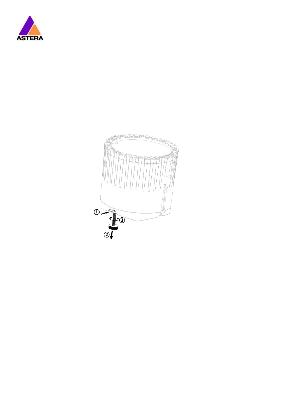
The AX5 TriplePAR™ is fitted with a kickstand that can be used to tilt the AX5
It can be used to tilt the AX5:
STEP 1: Press the button, the kickstand will jump out
STEP 2: Adjust the kickstand while holding the button pressed
STEP 3: Rotate the kickstand for fine-tuning
Astera LED Technology GmbH
User Manual for AX5 TriplePAR™ 2017-09-08
Page | 9
3.4 FILTER
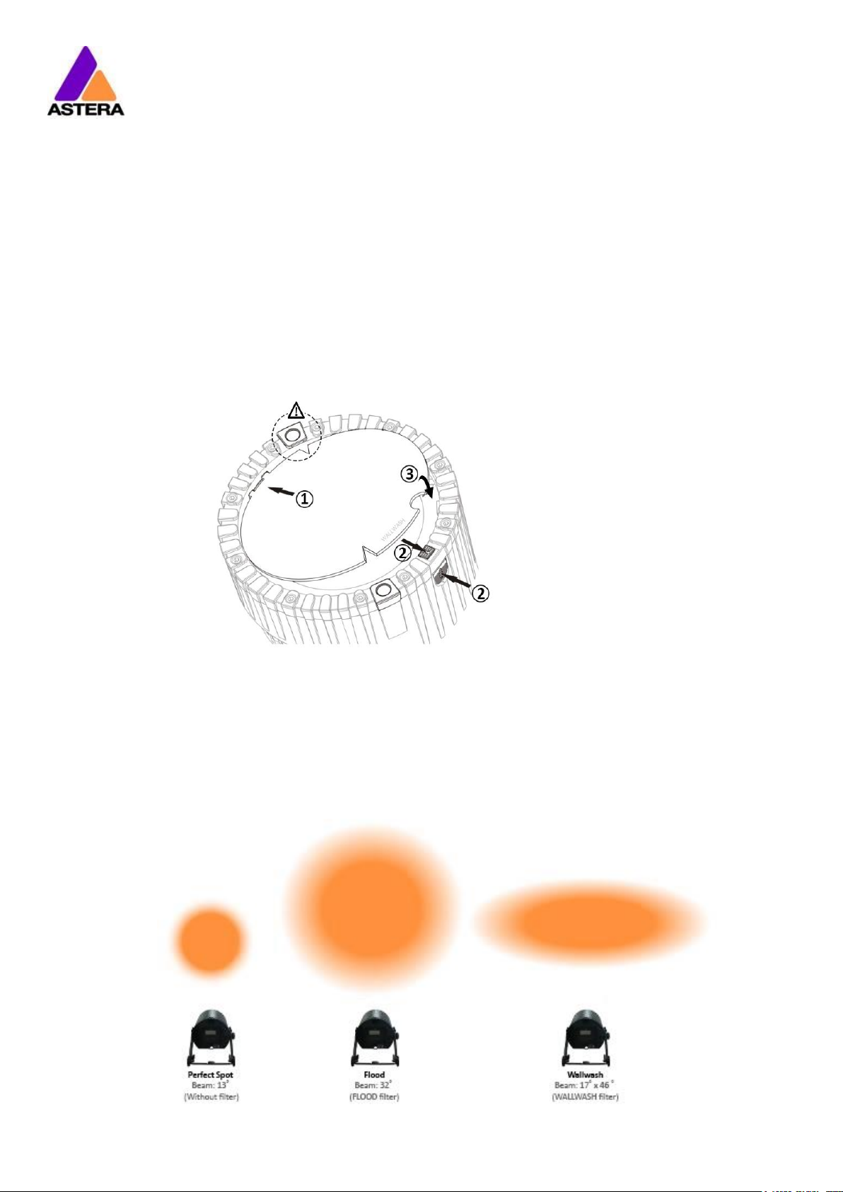
INSERT A FILTER:
STEP 1: Slide the filter noses into the matching slots. When using the
Wallwash Filter, make sure to align its triangles with the charging
pins to ensure its elliptical beam gets displayed correctly.
STEP 2: Open the filter release by either pressing the button from the side
or pulling it from the top outwards.
STEP 3: Press the filter down firmly, then stop holding the filter release to
lock in the filter
REMOVE A FILTER:
Open the filter release, put your finger into the cutout half-circle and lift the
filter out.
FILTER EFFECT:

Astera LED Technology GmbH
User Manual for AX5 TriplePAR™ 2017-09-08
Page | 10
3.5 BATTERY
WHILE RUNNING ON BATTERY, THE LIGHT ADJUSTS ITS OUTPUT TO MEET THE
REQUIRED MINIMUM RUNTIME. IT CAN BE SET BY THE CONTROL PANEL (0
Astera LED Technology GmbH
User Manual for AX5 TriplePAR™ 2017-09-08
Page | 11
R) or the AsteraApp™ between one and twenty hours.
The battery is specified to last for 300 full discharge cycles. Its runtime will have decreased to
70% by then. To increase the battery life it is recommended to recharge as early as possible
and not let the light run until the battery is depleted.
If operated below 20°C, the battery runtime may be slightly shorter than predicted. This is also
true if the lights are stored for a long time at cold temperature right before they are used.
The light is constantly monitoring the LED temperature and dims down the brightness if it
exceeds 65°C. That ensures a save and long-live operation but in a hot environment the
brightness might be slightly lower.
NOTE:
Always store the lights with full battery.
Depleted batteries must be recharged immediately, otherwise their performance will suffer.
ATTENTION:
The battery may be only replaced with an original Astera replacement battery.
3.5.1 STANDBY
By using the AsteraApp™, the light can be set to a special standby mode.
In that mode, its ouput is switched off, the CRMX receiver is powered down and it enters a
state of low power consumption.
A full battery will supply the SpotLite™ roughly 20 days in standby mode.
To light leaves the standby mode if the ENTER key is pressed or the standby mode is left by the
AsteraApp™.
3.6 BATTERY ICON AND STATUS LED
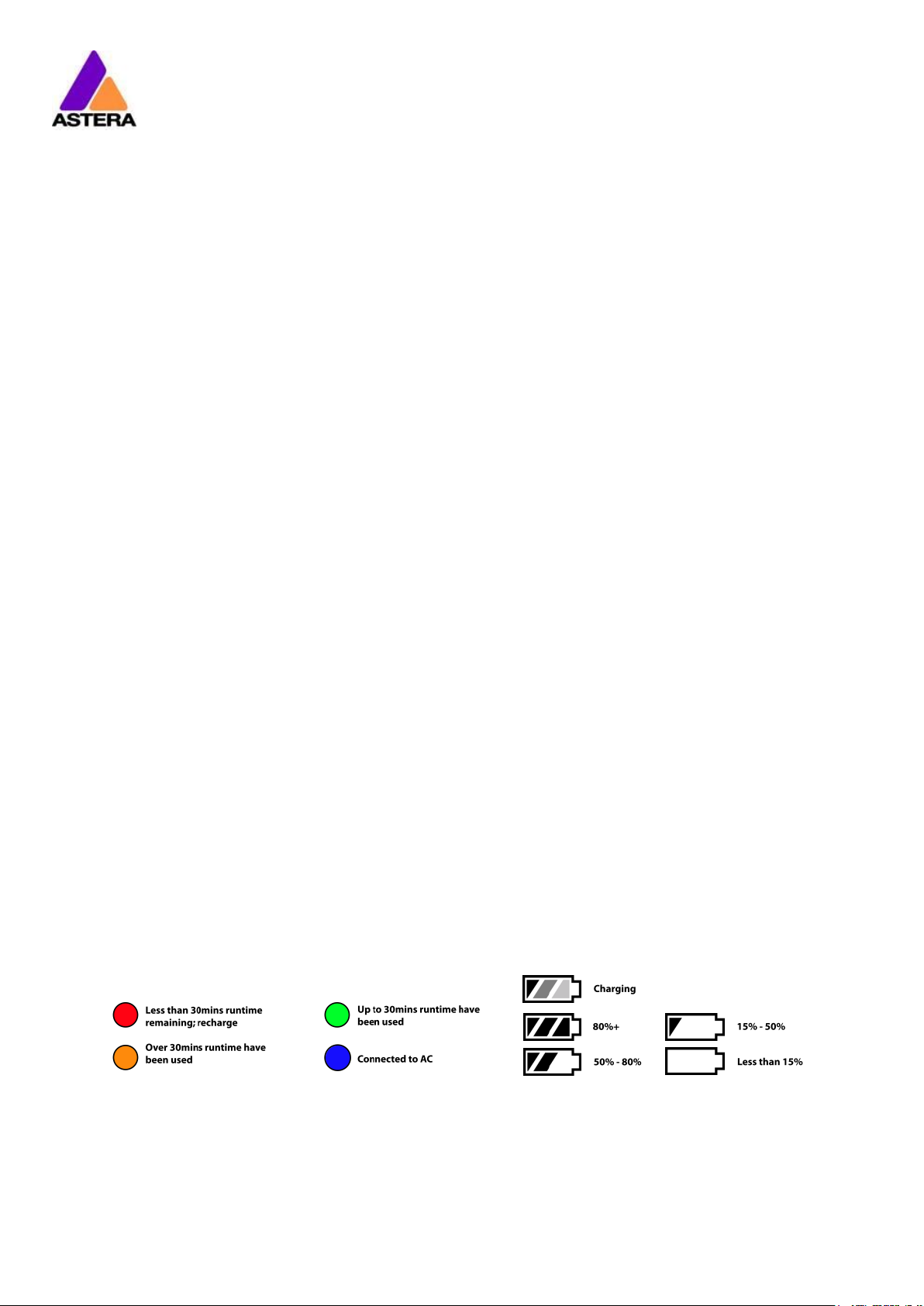
The Battery Status LED is designed for being used before an event. All fixtures should have a
green Status LED to ensure that the battery lasts for your upcoming event. If it is another color,
recharging is recommended.
While the light is connected to AC, the Status LED will be blue. While it is charging, the Battery
Icon will start the charging sequence. Once the battery is fully charged the battery icon on
the display will show all 3 bars (as below). If the battery is already fully charged and the
power cord is plugged in, the display will show a battery with moving bars for approx. 30-60
seconds after which it will stop and the icon will show a full battery.
3.7 CHARGING
Charge the light immediately after use.

Astera LED Technology GmbH
User Manual for AX5 TriplePAR™ 2017-09-08
Page | 12
If charged in a flight case, make sure it is open. It is recommended to charge the lights at an
ambient temperature between 0°C and 35°C. A normal charge cycle will take five to seven
hours, but may take much longer if the light is hot.
The light is designed to be charged while powered off. If it is connected to AC and powered
on, it may charge at reduced current if enough power is available and the battery
temperature is below 45°C.
The light has an automatic battery bypass switch, so it can safely be used wired, this will not
cause wear to the battery.
3.8 CHARGING CASE
Insert light into a tray of the charging case. The orientation/polarity does not matter. Make
sure the charging case is connected to the AC power.
The battery is being charged.
The battery is fully charged. The LCD backlight will turn off.
The battery cannot be charged, it is too hot. The charger will
start once it has cooled down below 45°C.
The battery cannot be charged, it is too cold. The charger will
start once it has heated up to at least 5°C.
The battery cannot be charged, the error number should be
mentioned to the service.
Charging…
[===== ] 50%
Fully Charged
[===========]100%
TOO HOT: 60°C
[====== ] 50%
TOO COLD:-5°C
[====== ] 50%
ERROR:#5
[====== ] 50%
Astera LED Technology GmbH
User Manual for AX5 TriplePAR™ 2017-09-08
Page | 13
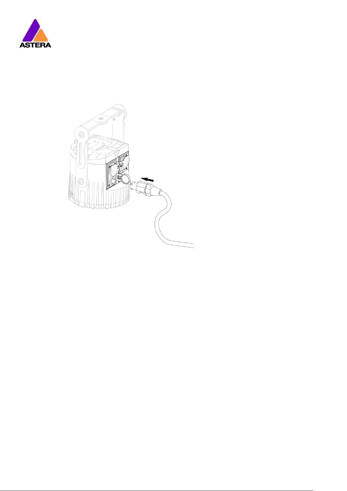
3.9 AC WIRING
The light is equipped with Neutrik True1 Powercon input and output connectors. With this
cable the light can be charged or wired for permanent installations.
They are rated IP65 even while a connector is plugged in.
Astera LED Technology GmbH
User Manual for AX5 TriplePAR™ 2017-09-08
Page | 14
4 SPECIFICATION
LED power:
45W
Illuminants:
3 x 15W RGBAW Philips LEDs
Luminous Flux*:
1080Lm (bei Weiß 3200K)
Emittance*:
4800lx (2m; Weiß 3200K)
Beam Angle:
13°
Input Voltage:
90-264V 47-63Hz 1.8A/115VAC 1.0A/230VAC
Inrush Current:
COLD START 70A/230VAC
Battery Runtime:
up to 20hrs (seamless runtime)
Wireless Module:
EU: 868.0-869.7 MHz
US: 902-928 MHz
2.4 GHz
Operating Temperature:
0°C – 40°C
32°F – 104°F
Relative Humidity:
0%-100%
Size with bracket:
Size without bracket:
L148.1mm x W193.6mm x H213.5mm / 5.83” x 7.62” x 8.40”
Ø153.2mm x H140.5mm / Ø6.03” x H5.53”
Weight:
3.40 kg
7.5lbs
IP Rating:
IP65
* Typical Values
5 TROUBLESHOOTING
The fixture does not turn on.
The battery may be empty. Connect it to the AC and try again.
The fixture turns on and the display is on, but the LEDs do not emit light.
The fixture could be set to BLACKOUT mode, set to display black color or is operating in DMX
mode and doesn’t receive a valid signal. It is good practice to do a RESET SETTINGS (Chapter
6.21) between setups.
The fixture is not working correctly - it does not display the color or effect chosen.
The fixture may still be operating under a previous setting. It is good practice to do a RESET
SETTINGS (Chapter 6.21) between setups.
After completing a RESET SETTINGS, the fixture still cannot be controlled by AsteraApp™.
Make sure the RADIO PIN (Chapter 6.20) of the fixture and AsteraApp™ is the same.
The fixture does not run long enough on battery.
The required RUNTIME can be set. It defaults to 5h. To achieve a greater battery runtime, set
the RUNTIME to the required value. Alternatively, program the fixture to only display colors
that use less power, such as Red, Green and Blue.
If the runtime is still too short, consider that it is reduced slightly if the battery is very cold.
The power cable is connected but the fixture is not charging.
The battery may be fully charged. Refer to chapter 3.5.1 for more details. The fixture will only
commence charging when its battery has a temperature of 45° or less. Turn the fixture off and
let it cool down; once cold enough, it will start charging. If it still not charging, consult our
website.

Astera LED Technology GmbH
User Manual for AX5 TriplePAR™ 2017-09-08
Page | 15
6 OPERATION
6.1 ASTERARGB COLOR SPACE
The lights work with a specially optimized RGB color space, the AsteraRGB color space. It is
designed to eliminate the need to control each color individually to display a certain color.
Instead, the light calculates the optimum combination of all colors based on an RGB value. It
considers each LED chip’s temperature as well as an optimal color rendering.
Due to this, it is possible to reproduce colors with high accuracy. It is possible to calculate an
AsteraRGB representation for any CIE color. The easiest way to do this is with the AsteraApp™:
• Go to the color picker and add a new favorite color
• Go to favorite colors and edit it
The dialog on the right will open.
It allows you to find AsteraRGB values for a certain color
temperature. S-RGB or CIE1931 values can be calculated to
AsteraRGB by pressing the corresponding buttons.
The primaries of the AsteraRGB are defined as:
White Point
x
y
0.4917
0.4878
The light also includes the Dynamic Powerboost feature. It ensures that colors that consume
less electrical power are boosted slightly, while power power-consuming colors are slightly
compressed.
This maximizes the brightness while maintaining the desired battery runtime.
While controlling with the AsteraApp™ or by the Control Panel, only RGB values can be set.
By DMX control, it is possible to control all colors separately. But it should be noted, that then
temperature compensation is only available for Red, Green and Blue; all other colors will
experience temperature drift, their brightness will not be constant.
Red
Green
Blue
xR
yR
xG
yG
xB
yB
0.7079
0.2920
0.1750
0.7200
0.1566
0.0177
Astera LED Technology GmbH
User Manual for AX5 TriplePAR™ 2017-09-08
Page | 16
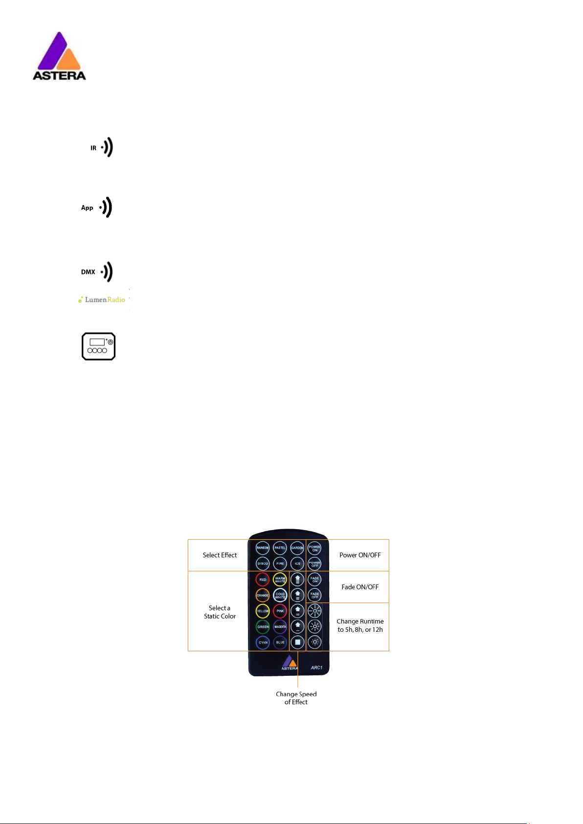
6.2 WAYS TO CONTROL
The light can be controlled in several ways:
Use Astera’s ARC1 infrared remote control, point it at individual lights and
press the desired effect. Note that the IR sensor is on the AX5’s rear side.
The AsteraApp™ is an efficient way to quickly create a customized light
show. It can group several lights together, address individual lights or groups
of lights, and send complex effects with a user defined color palette to all
lights in range. For additional information refer to chapter 7.
Alternatively, the Astera ARC2 remote control can be used.
The light can also be controlled by CRMX wireless DMX, the built in receiver is
compatible with all LumenRadio CRMX transmitters as well as W-DMX™ G2,
G3, G4 and G4S transmitters (G4 and G4S in 2.4 GHz mode only).
You can also use an Astera ART3 Wireless DMX Transmitter to send DMX in the
UHF frequency band, although CRMX is the recommended method.
Power the light on/off, set a static color or change its settings.
CRMX is a trademark of LumenRadio AB
W-DMX is a trademark of Wireless Solution Sweden AB
6.3 CONTROL BY INFRARED WITH ARC1
The light can be controlled by the infrared remote control if:
• INPUT SELECT is set to AUTO or REMOTE CONTROL (refer to chapter 6.11).
• The light is currently NOT operated by DMX. If it is, only ON and OFF will work while
INPUT SELECT is set to AUTO.
The ARC1 is very handy to switch several lights on or off at a time.

Astera LED Technology GmbH
User Manual for AX5 TriplePAR™ 2017-09-08
Page | 17
6.4 CONTROL BY THE ASTERAAPP™
Your light has a built in standalone engine. It can display static colors or replay a number of
predefined effect patterns with a customizable color palette.
With the AsteraApp™ these effects can be created and be sent to the light by the built in
UHF receiver. The effects are just triggered and then each light replays it autonomously until it
receives a new effect.
Lights can be grouped into sets. This way they can be controlled separately and also effects
can stretch over up to 32 lights.
Also, you can remotely adjust your lights settings, this eases DMX setup for example.
For more details refer to chapter 7.
6.5 CONTROL BY WIRELESS DMX
To pair your light to a CRMX or W-DMX™ transmitter, make sure that:
• Your light is not currently paired to a transmitter. To unpair it refer to chapter 6.17.
• INPUT SELECT is either set to AUTO and the light is still in detect mode –or- INPUT SELECT
is set to CRMX wireless DMX; for details refer to chapter 6.11.
Then press the button on your transmitter. After 10 seconds the light should be paired and
show the appropriate status screen (chapter 6.8).
If you prefer to use an Astera ART3 wireless transmitter, set INPUT SELECT to Astera wireless DMX
and refer to the ART3’s user manual for details.
NOTE:
If you experience difficulties pairing your light, it is recommended to set INPUT SELECT to CRMX
wireless DMX first. This will make sure that the CRMX status screen is displayed.
6.6 CONTROL BY WIRED DMX
The light can be connected to a DMX console by the XLR connectors.

Astera LED Technology GmbH
User Manual for AX5 TriplePAR™ 2017-09-08
Page | 18
6.7 CONTROL PANEL
6.7.1 Blue Mode
Blue mode is an easy way to pair your light with the AsteraApp. To enter Blue Mode, hold
down the POWER button for 3 seconds while the light is switched on. It will start to flicker blue.
6.8 STATUS SCREEN
The status screen is shown after power up. The light also returns to the status screen if no keys
are pressed for three minutes.
It shows:
• In the FIRST line what input is currently active
• In the SECOND line the current DMX and SET address
INPUT SELECT is set to AUTO and the light did not yet latch to
one input source.
The light is latched to REMOTE CONTROL mode.
INPUT SELECT is set to STANDALONE. The light can no longer be
controlled by any wireless signal.
The light is latched to CRMX mode.
The light is latched to Astera wireless DMX mode.
Emergency light mode can be active because either AC FAIL
or DMX FAIL being set to EMERGENCY LIGHT.
The standby mode saves power; the light is off and waiting for
a “leave standby” command received by the AsteraApp™.
Theft alarm is active.
If the AsteraApp is asking to “tap a light” and this is shown,
press the ENTER key shortly to accept.
INPUT: DETECTING
SET:001 DMX:001
REMOTE CONTROL
SET:001 DMX:001
STANDALONE
SET:001 DMX:001
CRMX: SIGNAL 99%
SET:001 DMX:001
WLDMX: NO LINK
SET:001 DMX:001
EMERGENCY LIGHT
SET:001 DMX:001
STANDBY
SET:001 DMX:001
ALARM
DO NOT STEAL THI
ACCEPT CONFIG ?
SET:001 DMX:001

Astera LED Technology GmbH
User Manual for AX5 TriplePAR™ 2017-09-08
Page | 19
6.9 MAIN MENU OPTIONS
The main menu can be entered from the status screen by pressing MENU or +. To cycle
between the main menu entries, press the + or – keys. Pressing MENU again will go back to
the status screen.
Used to change the input source or set it to AUTO.
Entering this menu resets all STANDALONE settings to default
and makes the light display a static color.
Set the DMX address.
Set the DMX parameters.
Unpair from a CRMX or W-DMX™ transmitter.
Set the lights runtime on battery in hours.
Set parameters of the standalone engine.
The light can react to the loss of AC power input.
Information about the light: radio pin, firmware version, battery
status, ect.
Reset all user settings to default. Should be done after each
usage to ensure consistent behavior. The RADIO PIN is NOT
reset.
6.10 MENU SHORTCUTS
To get to the DMX address setting, press the ENTER key twice from the status screen.
To open the DMX settings menu, press ENTER, then the + key and ENTER again.
To reset the light to default settings, press the – key, then ENTER and again ENTER.
Main menu:
INPUT SELECT
Main menu:
STATIC COLOR
Main menu:
DMX ADDRESS
Main menu:
DMX SETTINGS
Main menu:
UNPAIR CRMX
Main menu:
RUNTIME
Main menu:
STANDALONE
Main menu:
AC FAILURE
Main menu:
INFO
Main menu:
RESET SETTINGS

Astera LED Technology GmbH
User Manual for AX5 TriplePAR™ 2017-09-08
Page | 20
6.11 INPUT SELECT
The light accepts several input sources. By default, it is set to AUTO. In this mode, it listens to all
sources, and the first source that becomes active is latched. Once a source is latched, the
light will not listen to any other source anymore.
This latched source is cleared by powering down the light or changing the INPUT SELECT
manually.
Auto mode; the lights waits for
any input signal and latches the
first detected source.
In standalone mode, neither
wireless DMX nor remote control
is accepted.
The light can be control by the
AsteraApp™, but any DMX
signal is ignored.
Only Astera wireless DMX is
accepted, all other sources are
ignored.
Only CRMX/W-DMX wireless
DMX is accepted, all other
sources are ignored.
The following table shows what sources are accepted for each setting:
Source INPUT SELECT
AUTO, none latched AUTO, STANDALONE latched AUTO, REMOTE CONTROL
latched AUTO, Astera wir
el. DMX latched
AUTO, CRMX wirel. DMX latched STANDALONE REMOTE CONTROL Astera wirel. DMX CRMX wirel. D
MX
AsteraApp™: change colors
● ● ●
AsteraApp™: STANDBY, RUNTIME, ALARM
● ● ● ● ● ●
AsteraApp™: DMX Settings
● ● ● ● ● ● ● ●
Astera Wireless DMX
● ● ●
CRMX Wireless DMX
● ● ●
Infrared Remote
● ● ● ● ● ●
The Light’s Control Panel
● ● ● ● ● ● ● ● ●
HINT:
To avoid the light automatically latching onto CRMX while you want to control it by remote
control, please do UNPAIR CRMX (chapter 6.17). As soon as the remote control is latched, the
CRMX receiver will no longer accept pairing requests.
Main menu:
INPUT SELECT
INPUT SELECT
AUTO
INPUT SELECT
STANDALONE
INPUT SELECT
REMOTE CONTROL
INPUT SELECT
Astera wirel.DMX
INPUT SELECT
CRMX wirel. DMX

Astera LED Technology GmbH
User Manual for AX5 TriplePAR™ 2017-09-08
Page | 21
6.12 SELECT A STATIC COLOR
To make the light show a static color, enter this menu. Immediately when it’s entered, all
previous STANDALONE settings are cleared to default and the INPUT SELECT is latched to
STANDALONE. This is valid until the next power-up only. To make sure the light also shows a
static color after the next power up, set INPUT SELECT to STANDALONE and not AUTO.
A number of predefined colors
are available while scrolling
through the menu. See below
for a full table.
By entering the INDEX COLOR
menu, a number of predefined
colors similar to those of
common gels are available for
selection.
To set a color by its red, green
and blue value, enter here.
6.12.1 Predefined Colors
Color
Red
Green
Blue
RED
255 0 0
ORANGE
255
107
0
YELLOW
255
160
18
GREEN
0
255
0
CYAN 0 255
224
BLUE 0 0
255
VIOLET
127
84
255
PINK
255
53
119
BLACK 0 0
0
2700K
255
166
70
3200K
255
178
89
4000K
255
193
115
5500K
255
211
150
6500K
255
219
167
Main menu:
STATIC COLOR
Static Color:
RED
Static Color:
6500K
Static Color:
INDEX COLOR
Static Color:
CUSTOM COLOR

Astera LED Technology GmbH
User Manual for AX5 TriplePAR™ 2017-09-08
Page | 22
6.13 DMX SETTINGS
A number of DMX tables are
available, see below for details.
For each of the tables, the
strobe channel can be enabled
or disabled.
A number of dimmer curves are
available while the light is
controlled by DMX.
If the DMX signal is lost, the light
can either HOLD the current
output, switch to STANDALONE
operation, to BLACK or
EMERGENCY LIGHT, which
means white 4000K. See
chapter 5.12
6.13.1 DMX Tables
Each of the tables can optionally contain a strobe channel. It can be switched on or off by
the STROBE menu. The tables below list it, but in case it is set to OFF, the DMX-channels are
unused.
6.13.1.1 RGB S
CHANNEL
VALUE
FUNCTION
1
0..255
RED 2 0..255
GREEN 3 0..255
BLUE
4 STROBE (only if STROBE is ON)
0..3
OFF 4
RANDOM FAST
5 RANDOM MEDIUM
6 RANDOM SLOW
7..255
Variable strobe
6.13.1.2 RGBW S
CHANNEL
VALUE
FUNCTION
1
0..255
RED 2 0..255
GREEN
3
0..255
BLUE
4
0..255
WHITE 5
STROBE (only if STROBE is ON)
0..3
OFF 4
RANDOM FAST
5 RANDOM MEDIUM
6 RANDOM SLOW
7..255
Variable strobe
6.13.1.3 RGBAW S
CHANNEL
VALUE
FUNCTION
1
0..255
RED 2 0..255
GREEN
3
0..255
BLUE
4
0..255
FREE (this light does not have AMBER LEDs)
5
0..255
WHITE
6 STROBE (only if STROBE is ON)
0..3
OFF
Main menu:
DMX SETTINGS
DMX Settings:
DMX TAB
DMX Settings:
STROBE
DMX Settings:
DIMMER CURVE
DMX Settings:
DMX FAIL

Astera LED Technology GmbH
User Manual for AX5 TriplePAR™ 2017-09-08
Page | 23
4 RANDOM FAST
5 RANDOM MEDIUM
6 RANDOM SLOW
7..255
Variable strobe

Astera LED Technology GmbH
User Manual for AX5 TriplePAR™ 2017-09-08
Page | 24
6.13.1.4 RGB CCT DIM IND S
CHANNEL
VALUE
FUNCTION
1
0..255
RED 2 0..255
GREEN
3
0..255
BLUE
4 COLOR TEMPERATURE (CCT)
0..4
no effect
4..255
display color temperature; CCT overwrites the RGB setting
Formular: CCT = 2000 + 20*DMX-Value
Example: 50 -> 3000K
100 -> 4000K
150 -> 5000K
5
0..255
Dimmer
6 INDEX COLOR
0..4
no effect
4..255
display index color (common gels); INDEX COLOR overwrites both, RGB
and CCT. 7
STROBE (only if STROBE is ON)
0..3
OFF
4 RANDOM FAST
5 RANDOM MEDIUM
6 RANDOM SLOW
7..255
Variable strobe
6.13.1.5 DIM RGB S
CHANNEL
VALUE
FUNCTION
1
0..255
Dimmer 2 0..255
RED 3 0..255
GREEN 4 0..255
BLUE 5
STROBE (only if STROBE is ON)
0..3
OFF 4
RANDOM FAST
5 RANDOM MEDIUM
6 RANDOM SLOW
7..255
Variable strobe
6.13.1.6 DIM RGBW S
CHANNEL
VALUE
FUNCTION
1
0..255
Dimmer 2 0..255
RED
3
0..255
GREEN
4
0..255
BLUE 5 0..255
WHITE 6
STROBE (only if STROBE is ON)
0..3
OFF 4
RANDOM FAST
5 RANDOM MEDIUM
6 RANDOM SLOW
7..255
Variable strobe
6.13.1.7 DIM RGBAW S
CHANNEL
VALUE
FUNCTION
1
0..255
Dimmer
2
0..255
RED
3
0..255
GREEN 4 0..255
BLUE
5
0..255
FREE (this light does not have AMBER LEDs)
6
0..255
WHITE 7
STROBE (only if STROBE is ON)
0..3
OFF 4
RANDOM FAST
5 RANDOM MEDIUM
6 RANDOM SLOW
7..255
Variable strobe

Astera LED Technology GmbH
User Manual for AX5 TriplePAR™ 2017-09-08
Page | 25
6.13.1.8 Effect Modes
There are two effect modes available. They offer a comprehensive control of the built in
standalone engine. Settings that can otherwise only be changed on the LCD menu or by the
AsteraApp™ can be directly adjusted by DMX. The two effect modes only differ in the way
the color palette of four colors is set: either by RGB or by a single channel, like a color wheel.
In that case, common gels can be selected directly. Strobe is always enabled for the effect
modes.
CHANNEL
VALUE
FUNCTION
EFFECT
MODE FIX
EFFECT
MODE RGB 1 1
0..255
INTENSITY 2 2 STROBE
0..3
OFF 4 RANDOM FAST
5
RANDOM MEDIUM
6
RANDOM SLOW
7..255
Variable strobe
3 3
PROGRAM:
0..7
ONE COLOR STATIC
8..15
TWO COLOR STATIC
16..23
THREE COLOR STATIC
24..31
FOUR COLOR STATIC
32..39
ONE COLOR FADE
40..47
TWO COLOR FADE
48..55
THREE COLOR FADE
56..63
FOUR COLOR FADE
64..71
SIMPLE RUNNING
72..79
DOUBLE RUNNING
80..87
TWO COL RUNNING
88..95
FLAG RUNNING
96..101
DOUBLE FLAG RUNNING
102..109
SPIRAL 4 COLOR
110..117
SPIRAL 2 COLOR
118..125
RAINBOW
126..133
FIRE
134..141
ROTOR
142..149
ROTOR SPLIT 2
150..157
ROTOR SPLIT 4
4 4 0..255
SPEED 5 5
0..255
FADE 6 6 DIRECTION:
0..63
FFW+LOOP
64..127
FFW
128..190
REW
191..255
REW+LOOP 7 7 SIZE:
Defines the virtual size of the program in groups. For example if SIZE is set to 2 groups, only half of the program is shown on
the unit.
0..63
1 Group
64..127
2 Groups
128..190
3 Groups
191..255
4 Groups 8 8 OFFSET:
0..255
If SIZE is set to >1 group, the units pixels can be shifted within the virtually larger
program. Increasing the OFFSET parameter scrolls the position of the unit within the virtual large program.
9 9 0..255
RESTART PROGRAM
if value is changed, the program starts again from the beginning (useful if
DIRECTION is not set to loop)
10
INDEX COLOR 1
11
INDEX COLOR 2
12
INDEX COLOR 3
13
INDEX COLOR 4
10
RED 1 11
GREEN 1 12
BLUE 1 13
RED 2 14
GREEN 2 15
BLUE 2
16
RED 3
17
GREEN 3 18
BLUE 3 19
RED 4 20
GREEN 4 21
BLUE 4

Astera LED Technology GmbH
User Manual for AX5 TriplePAR™ 2017-09-08
Page | 26
6.14 DIMMER CURVE
The dimmer curve sets how the light responds to intensity levels and changes. Most important,
setting the right dimmer curve avoids steppy dimming response.
Several curves are available. By default, the “STANDARD” curve is active.
Name
Intended use
Features
FAST
For Pixel mapping and similar applications
Totally unfiltered response
STANDARD
Good compromise between response and
smoothness
Fits most applications
HALOGEN
When slow and smooth dimming is
required
Very smooth response, emulating a
halogen light
THEATER
For theater stages
Very smooth response and increased
dynamics. Some colors are darker.
TV
For TV sets and shows
Faster but still smooth dimming. Less
blue light due to white point of 6500K.
Less blue light. Increased dynamics.
Some colors are darker.
6.15 DMX FAIL
It can be set what the lights should do when the DMX signal is lost.
The last DMX input is still shown,
even if the DMX signal is lost.
The light will show a 4000K white
as soon as the DMX signal is lost.
The light will go dark if DMX
signal is lost.
The light will switch temporarily
to standalone mode if the DMX
signal is lost and show for
example a preset static color.
DMX Settings:
DMX FAIL
DMX FAIL
HOLD
DMX FAIL
EMERGENCY LIGHT
DMX FAIL
BLACKOUT
DMX FAIL
STANDALONE

Astera LED Technology GmbH
User Manual for AX5 TriplePAR™ 2017-09-08
Page | 27
6.16 RUNTIME
The light is able to adjust its
power to meet a certain
runtime on battery. The runtime
is always calculated for a full
battery.
EXAMPLE:
If the light is required to light during an eight hour event, and one hour of setup time is
scheduled, then the runtime should be set to nine hours immediately after the first power up.
Please note, that the light should not be stored below 20°C before an event, otherwise the
runtime might be shorter than calculated.
More details on the built in battery can be found at chapter 0.
For additional power-savings refer to the AsteraApp™ manual.
Main menu:
RUNTIME
RUNTIME
1h
RUNTIME
20h

Astera LED Technology GmbH
User Manual for AX5 TriplePAR™ 2017-09-08
Page | 28
6.17 UNPAIR CRMX
Once your light is paired to a CRMX or W-DMX™ transmitter, it cannot be paired to another
one until it is unpaired. This can be either done by using the button on the transmitter that is
currently paired or on the light directly.
If you wish to unpair your CRMX wireless DMX receiver from a Lumen Radio or W-DMX™
transmitter, go to UNPAIR CRMX and press enter.
NOTE:
The CRMX receiver is only powered while INPUT SELECT is:
• set to CRMX wireless DMX
• or AUTO and either CRMX is latched or no source is latched yet.
For details in INPUT SELECT refer to chapter 6.11.
Main menu:
UNPAIR CRMX

Astera LED Technology GmbH
User Manual for AX5 TriplePAR™ 2017-09-08
Page | 29
6.18 STANDALONE
Select one of the predefined
patters, see table below.
Sets the dimmer level.
The time that one cycle of the
program takes to complete.
The fade behavior between
each step of the program.
0% means, no fading
100% means full fading, fade-is
directly followed by fade-out.
The color palette of the
programs consist of up to four
colors. They can be set
individually. See chapter 6.12 for
details on how to set a color.
The AsteraApp™ can control
sets of lights individually. The set
address can be 1 to 254. This
setting is normally done by the
set-wizard in the AsteraApp™.
Several lights can form a virtual
“big” light. Programs like running
light will then run over all those
lights one by one. This
parameter tells how many lights
should form that virtual light; up
to 32.
Tells the lights position in the big
virtual light, 1..32.
Group addressing is supported
by the ARC2, please refer to the
ARC2 manual.
Main menu:
STANDALONE
Standalone:
PROGRAM
Standalone:
INTENSITY
Standalone:
SPEED
Standalone:
FADE
Standalone:
COLOR C1
Standalone:
COLOR C4
Standalone:
SET ADDRESS
Standalone:
SET SIZE
Standalone:
POS IN SET
Standalone:
GROUP ADDRESS

Astera LED Technology GmbH
User Manual for AX5 TriplePAR™ 2017-09-08
Page | 30
6.18.1 Predefined Programs
The predefined programs may use more than one pixel. To display these effects properly with
your light, it is first necessary to group them into Flow-Sets and control them by the
AsteraApp™ (see chapter 7.4).
If several lights are grouped into a Flow-Set, they form a virtual big light with several pixels.
Name
Pattern
ONE COLOR STATIC
A static color is displayed on the whole virtual light.
TWO COLOR STATIC
The virtual light is split into two halfs and two colors are displayed.
THREE COLOR STATIC
The virtual light is split into three parts and three colors are displayed.
FOUR COLOR STATIC
The virtual light is split into four parts and four colors are displayed.
ONE COLOR FADE
For all FADE programs, the whole color palette of four colors is used. Those
colors are faded in and out one by one.
Here, the whole virtual light shows the same color.
TWO COLOR FADE
The virtual light is split and shows two colors at a time.
THREE COLOR FADE
The virtual light is split and shows three colors at a time.
FOUR COLOR FADE
The virtual light is split and shows four colors at a time.
SIMPLE RUNNING
A running light; the background and the running pixels color can be set.
DOUBLE RUNNING
Two pixels are running in opposite direction.
TWO COL RUNNING
The two pixels are of different color even.
FLAG RUNNING
A three color flag is running over the background color.
DOUBLE FLAG RUNNING
Two flags are running over background in opposite direction.
SPIRAL 4 COLORS
The color is changed pixel by pixel. All four colors are used one after the
other.
SPIRAL 2 COLORS
The color changes between color 1 and 2 from the outside to the inside,
pixel by pixel.
RAINBOW
A rainbow effect is displayed.
FIRE
The fire effect is a random flicker between two colors, background and
flickering color.
NOTE:
It is highly recommended to check out the effects editor of the AsteraApp™ to get a better
understanding of how those programs work. Also, many programs look similar if the lamp is
NOT grouped into a Flow-Set.
6.19 AC FAILURE (EMERGENCY LIGHT)
The light can react to the loss of AC power in several ways. As soon as AC is present again,
the light resumes normal operation.
No special behavior on AC loss.
The light will turn dark if AC is
lost.
The light will switch to a 4000K
white as soon as the AC is lost.
Main menu:
AC FAILURE
AC FAILURE
NO ACTION
AC FAILURE
BLACKOUT
AC FAILURE
EMERGENCY LIGHT

Astera LED Technology GmbH
User Manual for AX5 TriplePAR™ 2017-09-08
Page | 31
6.20 INFO
Read/set the RADIO PIN. To
change the pin, press ENTER.
Adjust each digit with the + and
– keys, cycle through the digits
with the MENU key. When
finished, press ENTER again.
Tells the serial number of the
light and the CPU type (43xx).
The firmware version and
hardware version of the light.
The hour-counter is counting up
as long as the light is powered
up. It does not count if the light
is powered off and charging.
While the light is receiving an
UHF signal, this tells the signal
strength and deviation.
The current charging state of
the battery in percent.
Gives information about the LED
calibration stored in the light, for
service reference only.
6.21 RESET SETTINGS
Return the light to the default
settings. This may be done
before each use to start from a
known point. The RADIO PIN
and the CRMX pairing stay.
HINT
It is highly recommended to reset the light’s settings after each event to ensure a clear start
for the next usage.
Main menu:
INFO
Radio PIN:
0000
Serial number:
000-00000 43xx
Firmware version
5.2.20.U HW001
Power-on hours:
00001h
RF link:
-36.0dBm -0.0ppm
Battery state:
100%
Calibration:
2015-04-20-0001
Main menu:
RESET SETTINGS
ARE YOU SURE?
NO YES

Astera LED Technology GmbH
User Manual for AX5 TriplePAR™ 2017-09-08
Page | 32
7 USING THE LIGHT WITH THE ASTERAAPP™
The buttons of the AX5 only allow a basic operation of the light. To gain full control over all
features, the AsteraApp™ should be used.
The AsteraApp™ is an efficient way to quickly create a customized light show. It can group
several lights together, address individual lights or groups of lights, and send complex effects
with a user defined color palette to all lights in range.
Additionally, it can be used to adjust the lights settings remotely.
The AsteraBox™ is needed to interface your Android device with the lights. It communicates
to the Android device by Bluetooth and controls the lights by UHF.
7.1 PAIR YOUR LIGHT WITH THE ASTERAAPP™
The connection is secured by a 4 digit Radio Pin. Only if the
lights pin matches the AsteraApp™ pin, lights are controllable.
The pairing process transmits the radio pin from the app to the
light and stores it there.
1. Choose a unique Radio Pin in the app.
2. Switch the light into blue mode, see chapter 6.7.
3. Press the “Pair with Lights” button in the AsteraApp™.
NOTE:
Alternatively, you can set the Radio Pin manually at the Control Panel of the light. Refer to
chapter 6.20 for details.

Astera LED Technology GmbH
User Manual for AX5 TriplePAR™ 2017-09-08
Page | 33
7.2 POWERFUL LIGHT CONTROL
Your light has a built in standalone engine. It can display static colors or replay a number of
predefined effect patterns with a customizable color palette.
With the AsteraApp™ these effects can be created and be sent to the light by the built in
UHF receiver. The effects are just triggered and then each light replays them autonomously
until a new effect is sent.
Lights can be grouped into sets. This way they can be controlled separately and also effects
can stretch over up to 32 lights.
7.3 CHANGE THE COLOR
On the AsteraApp™ main
screen, press “Just Red”.
Once in the editor, press
“C1”.
Now the lights color can be
changed.
The “123” button offers
common color gels. Hit the
sort button to sort by color or
number (1).
To add a color to the
favorites, press (2).
To edit an existing favorite
color, select it and press the
pen (1).
The editor will open. RGB
values can be adjusted
directly. Also a color
temperature can be
converted to RGB.

Astera LED Technology GmbH
User Manual for AX5 TriplePAR™ 2017-09-08
Page | 34
7.4 CREATE A SET
Before the more powerful effects can be reviewed, it is recommended to create a Flow-Set
first.
Each light can be assigned to one set. Two types of sets are available:
7.4.1 SYNC SET
All lights that are assigned to a Sync-Set can be controlled together. They
will do exactly the same.
CREATE A SYNC-SET:
On the AsteraApp™ main
screen, first press the Targets
button (1) and then the “+”
sign (2) to add a new target.
Choose “Sync-Set”.
Now all lights will flicker
every two seconds. Tap your
light to add it to the set
(chapter 6.8Error! Reference s
ource not found.).
Additionally, the name of
the set can be customized.
When finished, press the
save button.
Astera LED Technology GmbH
User Manual for AX5 TriplePAR™ 2017-09-08
Page | 35
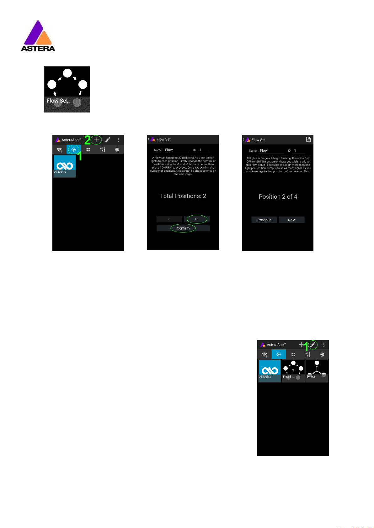
7.4.2 FLOW SET
By using a Flow-Set, lights can also be controlled together. But additionally,
they are assigned to positions inside the Flow-Set and so form a virtual light
with several pixels. All effects, like a running light, are stretched over this
virtual light.
CREAT A FLOW-SET:
On the AsteraApp™ main
screen, first press the Targets
button (1) and then the “+”
sign (2) to add a new target.
Then choose “Flow-Set”.
Each flow set can have up
to 32 positions. Once the
correct number is entered,
press “Confirm”.
Now your lights will flicker
every two seconds. To add a
light to the currently shown
positon of this set, press its
button. Walk through the
positions by “Previous” and
“Next” and assign your lights.
When finished, press the
save button on top.
7.5 TARGETING LIGHTS
Once you have created a set, you may now choose to control it. By
default “All lights” are targeted. That includes all sets.
It is possible to target more than one set at a time.
NOTE:
Even while targeting „All Lights” the Flow-Sets position arrangements
persist. The lights still form a virtual big light of several positions.
To modify, delete or arrange targets, use the pen button (1).

Astera LED Technology GmbH
User Manual for AX5 TriplePAR™ 2017-09-08
Page | 36
7.6 CHANGING THE EFFECT
On the AsteraApp™ main
screen, press “Wedding” (1),
then enter the editor (2).
Set “Crossfade” to 0% and
“Speed” to around 2
seconds. You should see a
clean running light now. The
White light will run over a
pink background.
The effect can be changed
by sliding the effect picker
and choosing a sub-effect
below it. Again the colors
can be adjusted, too.
After the effect is adjusted, it may be saved back to the main screen by pressing the save
button.
AN EFFECT CAN BE HIGHLY CUSTOMIZED:
The speed tells how long it will take for the effect to complete one cycle.
The crossfade tells if the light will fade from step to step. If it is set to 0% an immediate change
is visible. If set to 100% the changes will be soft.
Stroboscope effect can be enabled and seamlessly adjusted in speed. Additionally, three
random stroboscope options are available: slow, medium and fast.
Each effect can be adjusted in brightness as well.

Astera LED Technology GmbH
User Manual for AX5 TriplePAR™ 2017-09-08
Page | 37
7.7 LIST OF EFFECTS
The effects’ patterns are pre-defined and cannot be modified by the user. They are preprogrammed inside of each light. Still they can be parameterized. These effects are:
A static color is displayed. There are also options that show two, three or four
static colors at a time. The Flow-Set is then divided into several parts of equal
length:
Fading colors. The four defined colors are displayed one after the other. The
setup fade is applied between them. Again, the Flow-Set can be split in up
to four segments.
From both sides of a Flow-Set, the color changes position by position from C1
to C2. Once the whole Set is C2, it changes back to C1 in the same way.
The color of the Flow-Set changes position by position. After all positions
show the same color, a new cycle is started.
Several variations of running lights are available.
The Fire effect shows a random flickering effect. The background color and
the color of the flickering effect can be adjusted.
The rainbow effect shows a color change through all colors. Only its speed
can be adjusted.
Chaser effects provide an efficient means to create dancefloor lighting. The
static chaser exchanges the color of the lights according to the tapped-in
beat. The colors are randomly chosen. The effect can be adjusted to show
up to 4 different colors at a time.
The Moving Chasers overlay the static chaser by a second movement of the
four displayed colors over the available positions of a Flow-Set. This gets
mostly interesting of the Moving Strobe is chosen. Then, only some of the
positions strobe and they are moving. So the strobe effect moves over the
Flow-Set.
When using the Chaser With Background, additionally a color can be
selected that is mostly used, the background color.

Astera LED Technology GmbH
User Manual for AX5 TriplePAR™ 2017-09-08
Page | 38
7.8 CHASER EFFECTS IN DEEP
To display chaser effects it is recommended to setup a Flow-Set with a multiple of four
positions. This is the way they will be shown best. Those four positions could then be arranged
in the corners of a dance floor for example.
Use the tap-sync button to tap the beat of the music; the Chaser Effects will base their color
changing on that beat then.
The Chaser Effects offer additional controls
The Emphasis adjusts the way the colors are exchanged by the chaser:
Emphasis
Effect
-2
The four colors of the palette are exchanged one by one. Every beat changes
only one color.
-1
Same as “-2”, but the color change is animated with the color-wheel effect; it
mimics the color change of a traditional color wheel, showing intermediate
colors during the change.
0
All four colors are exchanged on every beat.
1
Same as “0”, but the color wheel effect is added.
2
Same as “0”, but on the fourth beat, all colors go black. They come on again
on the next beat.
3
Same as “0”, but all colors go black on every second beat. This setting
produces a strong on-off effect in sync with the beat.
The softness influences the fading between colors that happens on every beat. 0% will
generate a hard change of the colors, while 100% makes them fade very slowly.
A random button is added to the color bar. If it is latched, random colors are chosen on
every beat. If not (like in the above picture), then the colors are always chosen randomly
from the color pallet of four. This is useful to intentionally narrow down the color choice. Nice
effect can be generated by setting some of them to black.

Astera LED Technology GmbH
User Manual for AX5 TriplePAR™ 2017-09-08
Page | 39
7.9 THE MAIN SCREEN
Here each program is represented by a tile. Those tiles can be edited and freely positioned.
Several pages of tiles are available.
To move or delete a tile,
press the pen icon (2). A
popup will show the
available actions.
To add a new program tile,
press the “+” icon (1).
While adding a tile, either a
default “Static Red” or the
currently running program
can be selected.
Additionally, special function
tiles are available.
7.9.1 Function Tiles
Tapping this tile several times to the beat will let the Chaser Effects
change their colors to the beat. A chaser effect has a dancer symbol
on the tile.
This button can be used to quickly blackout lights. The currently set target
must be observed, as the blackout function will only affect the currently
targeted lights.

Astera LED Technology GmbH
User Manual for AX5 TriplePAR™ 2017-09-08
Page | 40
7.10 BRIGHTNESS
Additionally to each programs brightness slider mentioned in chapter 7.6, a master brightness
control is available.
As soon as more than one Set is created
and at least one set is currently
targeted, a sub-master for each Set is
shown.
Otherwise, only one slider is available. It
controls the brightness of all currently
targeted lights.
7.10.1 Set Sub-Masters
Each Set has its own brightness slider. Additionally, there is a master slider that controls the
brightness of all Sets simultaneously. This is very similar to the group brightness control of
common lighting desks.
NOTE:
The Set-Masters are only shown if:
a) More than one Set has been created before
b) Only Set-Targets are currently selected. Selecting any other type of target, like “All
Lights” will hide the Set-Masters. This is necessary to avoid that one lights gets
redundant brightness information; it would flicker constantly between different
brightness levels.
Astera LED Technology GmbH
User Manual for AX5 TriplePAR™ 2017-09-08
Page | 41
7.11 RUNTIME
The light is able to adjust its power to meet a certain runtime on
battery. The runtime is always calculated for a full battery.
Example:
If the light is required to light during an eight hour event,
and one hour of setup time is scheduled, then the
runtime should be set to nine hours immediately after the
first power up.
Please note, that the light should not be stored below 20°C
before an event, otherwise the runtime might be shorter than
calculated.
More details on the built in battery can be found at chapter 0.
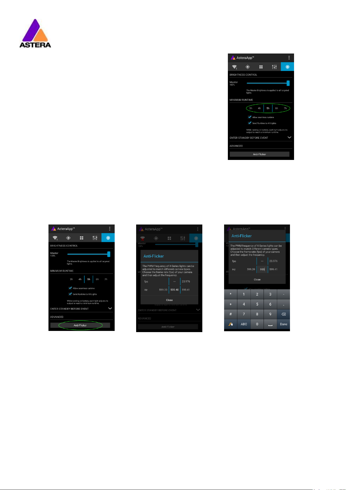
7.12 ANTI-FLICKER
The PWM refresh rate of this light is 599.4 Hz by default. This frequency can be freely adjusted
between 200 Hz and 1205 Hz to fit different camera’s frame rates.
Make sure you have
targeted the lights you wish
to adjust (chapter 7.5).
Then press the “Anti-Flicker”.
Slide the “fps” to adjust to
default values for a
framerate.
Slide the “Hz” to fine-adjust.
Press the highlighted
frequency to enter a custom
value between 200 and
1205 Hz.
NOTE:
The Anti-Flicker adjustment is preserved in case the lamp is powered off.
It is set back to the default 599.4Hz once a Reset Settings (chapter 6.21) is done.
The adjusted frequency is used no matter what input source is currently active. Also during
DMX operation.

Astera LED Technology GmbH
User Manual for AX5 TriplePAR™ 2017-09-08
Page | 42
7.13 THEFT ALARM
Your light is equipped with a theft alarm. A motion sensor in the light detects when it is
moved/taken away and a small siren will sound to deter potential thieves.
First make sure your Radio
Pin is different from 0000. See
chapter 7.1 how to change
it. Then press the “ON”
button.
Press “Activate”. All targeted
lights will flash shortly to
indicate that they are now
armed.
If the siren is set to DELAYED, it sounds only if the
alarm persists for more than 6 seconds. The ON
setting makes it sound immediately, while the OFF
setting mutes it always.
The sensitivity can be adjusted to meet your
environment. A lower value makes a false alarm
more unlikely.
In case a potential thief is taking the light away while
ignoring the alarm, he will most likely cause alarm
events for more than 2 minutes in a row. In that case,
the alarm can be set to become permanent. Then it
won’t stop, even if the light is placed down again. It
will run until the battery is empty, rendering the light
useless for the thief.
In some applications it is not desirable to have the
lights flashing while the alarm is enabled or disabled.
It can be disabled by this option easily.
The alarm can be silenced without turning it off by
pressing this button.
NOTE:
To turn the alarm off again, an AsteraApp™ with the same Radio Pin must be used. Do not
forget your Radio Pin! Otherwise, your light cannot be used normally anymore.

Astera LED Technology GmbH
User Manual for AX5 TriplePAR™ 2017-09-08
Page | 43
7.14 ENTER AND LEAVE STANDBY
The standby is intended to be used between setup and event (see chapter 3.5.1Error! R
eference source not found.). After setup is completed, all lights may be switched to standby
mode and woken up later when the event starts. This ensures that no battery runtime is
wasted. This can be either done manually or automated.
Press the small arrow to
open the standby menu.
By pressing the “Now”
buttons, standby can be
switched on or off for all
currently targeted lights.
Any of the “Later” buttons
will require a time to be set.
The standby will be
scheduled to the specified
time.
NOTE:
While you are using the “Now” function, only those lights that are currently targeted are
addressed (see chapter 7.5 how to target lights).
The “Later” function always sends to the “All Lights” target!

Astera LED Technology GmbH
User Manual for AX5 TriplePAR™ 2017-09-08
Page | 44
7.15 DMX SETTINGS
In order to efficiently use the light with DMX, some setting can be adjusted by the
AsteraApp™.
Press the “DMX
Configuration” button.
Adjust all settings to your
requirements, then press
“Send”.
Your lights will start to flicker.
Tap the lights you wish to
setup (chapter 6.8). Then
press “Done”.
Please refer to chapter 6.11, INPUT SELECT, and chapter 6.13, DMX Settings, for details on the
available settings.
7.15.1 DMX Channel Assignment
The current channel assignment can be always reviewed in
the lower part of the screen. It is automatically calculated
based on the setting of Table and Strobe.

Astera LED Technology GmbH
User Manual for AX5 TriplePAR™ 2017-09-08
Page | 45
8 MENU OVERVIEW

Astera LED Technology GmbH
User Manual for AX5 TriplePAR™ 2017-09-08
Page | 46
9 ATTACHEMENTS

Astera LED Technology GmbH
User Manual for AX5 TriplePAR™ 2017-09-08
Page | 47
VIEWS AND DIMENSIONS

Astera LED Technology GmbH
User Manual for AX5 TriplePAR™ 2017-09-08
Page | 48
10 VERSION HISTORY
26.06.2017
Initial version
27.06.2017
Rework safety instructions, attachments added
30.06.2017
First release version
11 STATEMENT
11.1 WARNING: CHANGES OR MODIFICATIONS TO THIS UNIT NOT EXPRESSLY
APPROVED BY THE PARTY RESPONSIBLE FOR COMPLIANCE COULD VOID THE
USER’S AUTHORITY TO OPERATE THE EQUIPMENT.
11.2 NOTE: THIS EQUIPMENT HAS BEEN TESTED AND FOUND TO COMPLY WITH THE
LIMITS FOR A CLASS B DIGITAL DEVICE, PURSUANT TO PART 15 OF THE FCC
RULES. THESE LIMITS ARE DESIGNED TO PROVIDE REASONABLE PROTECTION
AGAINST HARMFUL INTERFERENCE IN A RESIDENTIAL INSTALLATION. THIS
EQUIPMENT GENERATES, USES AND CAN RADIATE RADIO FREQUENCY ENERGY
AND, IF NOT INSTALLED AND USED IN ACCORDANCE WITH THE INSTRUCTIONS,
MAY CAUSE HARMFUL INTERFERENCE TO RADIO COMMUNICATIONS.
HOWEVER, THERE IS NO GUARANTEE THAT INTERFERENCE WILL NOT OCCUR IN A
PARTICULAR INSTALLATION. IF THIS EQUIPMENT DOES CAUSE HARMFUL
INTERFERENCE TO RADIO OR TELEVISION RECEPTION, WHICH CAN BE DETERMINED
BY TURNING THE EQUIPMENT OFF AND ON, THE USER IS ENCOURAGED TO TRY TO
CORRECT THE INTERFERENCE BY ONE OR MORE OF THE FOLLOWING MEASURES:
Reorient or relocate the receiving antenna.
Increase the separation between the equipment and
receiver.
Connect the equipment into an outlet on a circuit different
from that to which the receiver is connected.
Consult the dealer or an experienced radio/TV technician
for help.

Astera LED Technology GmbH
User Manual for AX5 TriplePAR™ 2017-09-08
Page | 49
11.3 THIS DEVICE COMPLIES WITH PART 15 OF THE FCC RULES. OPERATION IS
SUBJECT TO THE FOLLOWING TWO CONDITIONS:
(1) THIS DEVICE MAY NOT CAUSE HARMFUL INTERFERENCE, AND
(2) THIS DEVICE MUST ACCEPT ANY INTERFERENCE RECEIVED, INCLUDING
INTERFERENCE THAT MAY CAUSE UNDESIRED OPERATION.
11.4 SHIELDED CABLES MUST BE USED WITH THIS UNIT TO ENSURE COMPLIANCE WITH
THE CLASS B FCC LIMITS.
11.5 FCC RF RADIATION EXPOSURE STATEMENT CAUTION: THIS TRANSMITTER MUST
BE INSTALLED TO PROVIDE A SEPARATION DISTANCE OF AT LEAST 20 CM FROM
ALL PERSONS.
 Loading...