


DRAFT
User Manual
RFID Encoder
ASSA ABLOY Hospitality
1
66 1001 001-7

Copyrights
The information in this document is subject to change at the sole discretion of
ASSA ABLOY without notice.
Any use, operation or repair in contravention of this document is at your own risk.
ASSA ABLOY does not assume any responsibility for incidental or consequential
damages arising from the use of this manual.
All information and drawings in this document are the property of ASSA ABLOY.
Unauthorized use and reproduction is prohibited.
VingCard and Elsafe are registered trademarks of ASSA ABLOY.
ASSA ABLOY Hospitality
2
66 1001 001-7

Table of contents
.................................................................................................5 FCC and IC statements
........................................................................................................................ 5FCC statements
........................................................................................................................ 5Industry Canada statements
.................................................................................................6 1. Introduction
.................................................................................................7 2. To mount the encoder
........................................................................................................................ 72.1 Dimensions
........................................................................................................................ 82.2 Mounting kit
........................................................................................................................ 82.3 To mount on the wall
........................................................................................................................ 92.4 Card holder
.................................................................................................10 3. Electrical specification
........................................................................................................................ 103.1 Connectors
.................................................................................................11 4. To connect to Visionline or VingCard Vision
........................................................................................................................ 114.1 To connect to the Visionline server
................................................................................................................................................ 114.1.1 To connect via TCP/IP
................................................................................................................................................ 114.1.2 To connect via USB
................................................................................................................................................ 134.1.3 RFID encoder in SysMon
....................................................................................................................................... 134.1.3.1 To rename the encoder
........................................................................................................................ 144.2 To connect to VingCard Vision server or workstation
................................................................................................................................................ 144.2.1 To connect via TCP/IP
.................................................................................................15 5. Configuration utility
........................................................................................................................ 165.1 To configure for use with Visionline
........................................................................................................................ 185.2 To configure for use with VingCard Vision
.................................................................................................20 6. To factory reset the encoder
........................................................................................................................ 216.1 Default parameter values
.................................................................................................22 7. Web interface (Visionline only)
........................................................................................................................ 227.1 To modify the encoder parameters
.................................................................................................23 Appendix A: Quick reference of technical data
.................................................................................................24 Appendix B: To install the USBXpress driver
.................................................................................................25 Appendix C: To upgrade firmware
........................................................................................................................ 25To upgrade firmware via RFID Encoder Configuration Utility
........................................................................................................................ 26To upgrade firmware via SysMon
ASSA ABLOY Hospitality
3
66 1001 001-7

.................................................................................................27 Appendix D: Boot-up procedure
Appendix E: More about how the encoder finds the
.................................................................................................29
server (Visionline only)
........................................................................................................................ 30To commission encoders with DNS
................................................................................................................................................ 30Single server
................................................................................................................................................ 30Multiple servers
................................................................................................................................................ 31To commission encoders without DNS
........................................................................................................................ 31To switch to backup server
................................................................................................................................................ 31Single server - to switch to backup server with DNS
................................................................................................................................................ 31Multiple servers - to switch to backup server with DNS
................................................................................................................................................ 31To switch to backup server without DNS
.................................................................................................32 Revision history
ASSA ABLOY Hospitality
4
66 1001 001-7

FCC and IC statements
FCC statements
This device complies with Part 15 of the FCC Rules. Operation is subject to the
following two conditions:
(1) this device may not cause harmful interference, and
(2) this device must accept any interference received, including interference
that may cause undesired operation.
Note: This equipment has been tested and found to comply with the limits for a
Class A digital device, pursuant to part 15 of the FCC Rules. These limits are designed
to provide reasonable protection against harmful interference when the equipment
is operated in a commercial environment. This equipment generates, uses and can
radiate radio frequency energy and, if not installed and used in accordance with
the instruction manual, may cause harmful interference to radio communications.
Operation of this equipment in a residential area is likely to cause harmful
interference; in which case, correction of the interference is at the user's expense.
Important: Changes or modifications to an intentional or unintentional
radiator not expressly approved by the party responsible for compliance
could void the user's authority to operate the equipment.
The end product must be labeled to say 'FCC ID: Y7V-681001025C1'.
Industry Canada statements
This device complies with Industry Canada licence-exempt RSS standard(s).
Operation is subject to the following two conditions:
(1) this device may not cause interference, and
(2) this device must accept any interference, including interference
that may cause undesired operation of the device.
Le présent appareil est conforme aux CNR d’Industrie Canada applicables aux
appareils radio exempts de licence. L’exploitation est autorisée aux deux
conditions suivantes:
(1) l'appareil ne doit pas produire de brouillage, et
(2) l’utilisateur de l'appareil doit accepter tout brouillage radioélectrique subi,
même si le brouillage est susceptible d’en compromettre le fonctionnement.
The end product is labeled 'IC:9514A-681001025C1'.
The term "IC" before the equipment certification number only signifies that
the Industry Canada technical specifications were met.
Le terme "IC" devant le numéro de certification signifie seulement que les
specifications techniques Industrie Canada ont été respectées.
ASSA ABLOY Hospitality
5
66 1001 001-7
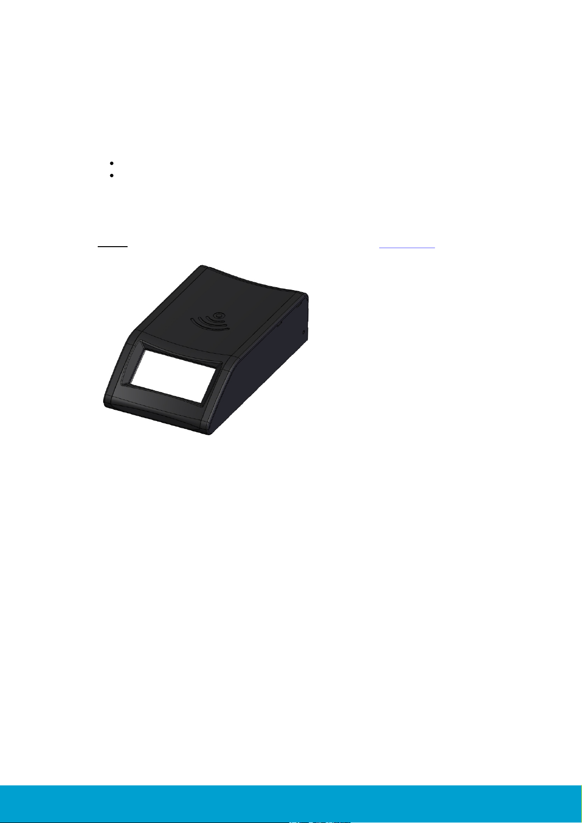
1. Introduction
Figure 1: RFID encoder
The RFID encoder is used for encoding and verifying RFID cards. It can be used
together with the below systems:
Visionline
VingCard Vision
Unless anything else is stated, the information in this document is valid for
both systems.
Note: For upgrade of firmware in the RFID encoder, see Appendix C.
ASSA ABLOY Hospitality
6
66 1001 001-7
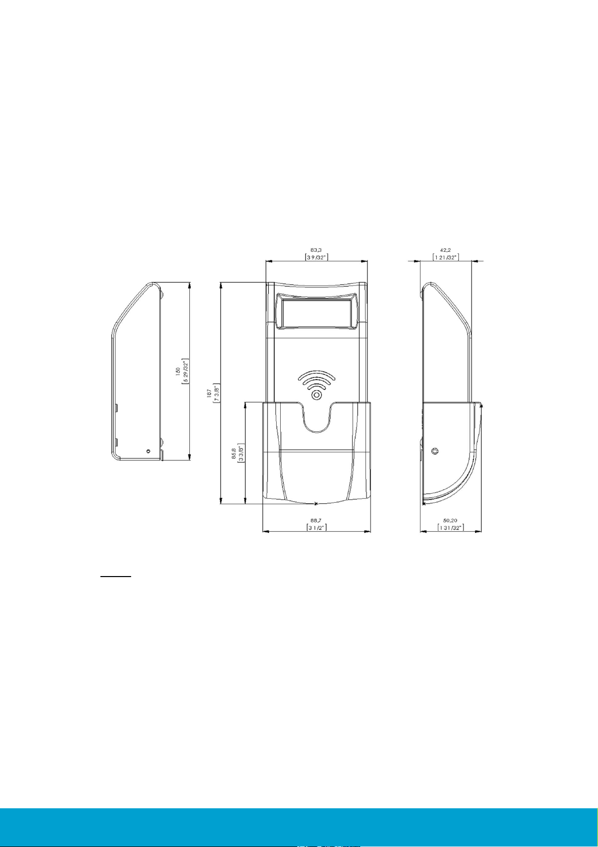
2. To mount the encoder
Figure 2: Encoder dimensions
The RFID encoder can either be mounted on a wall or be placed on a table etc;
dimensions in Figure 2 below in mm (inches).
2.1 Dimensions
Note: The RFID encoder can be mounted either horizontally or vertically.
ASSA ABLOY Hospitality
7
66 1001 001-7
2.2 Mounting kit
Description
Quantity
Usage
Screws 2,9x25mm
2
For mounting the RFID encoder on a wall
Collar screw 3,5x25mm
1
For mounting the RFID encoder on a wall
Screws 2,5x6,4mm
4
For mounting the card holder and mounting brackets
Expand plugs 6x30
3
Mounting brackets
2
Adhesive Velcro strips
2
If the RFID encoder should be mounted without using screws
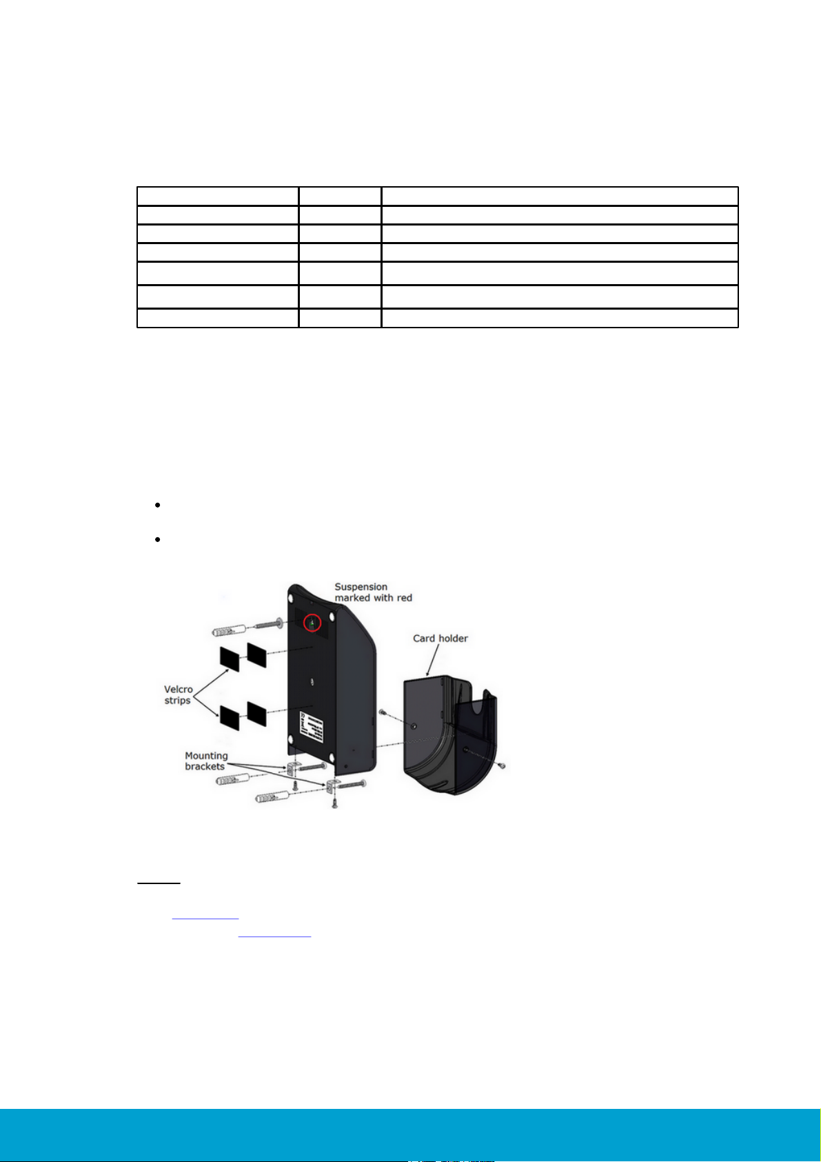
Figure 3: Exploded view of RFID encoder,
card holder and mounting details
The RFID encoder is delivered with a mounting kit containing the following items:
Table 1: Mounting kit
2.3 To mount on the wall
The encoder can be mounted on the wall either with the enclosed screws or with
the enclosed Velcro strips.
If the encoder should be mounted with screws:
fasten the mounting brackets at the bottom of the encoder with the two
mounting bracket screws
fasten the encoder on the wall with the collar screw at the suspension and
two screws at the mounting brackets
Note: When mounting the encoder on the wall, the parameter 'Wall mounted'
must be enabled; this can be done via the RFID Encoder Configuration Utility
(see chapter 5). If Visionline is applicable, it can also be done via the web
interface (see chapter 7).
ASSA ABLOY Hospitality
8
66 1001 001-7
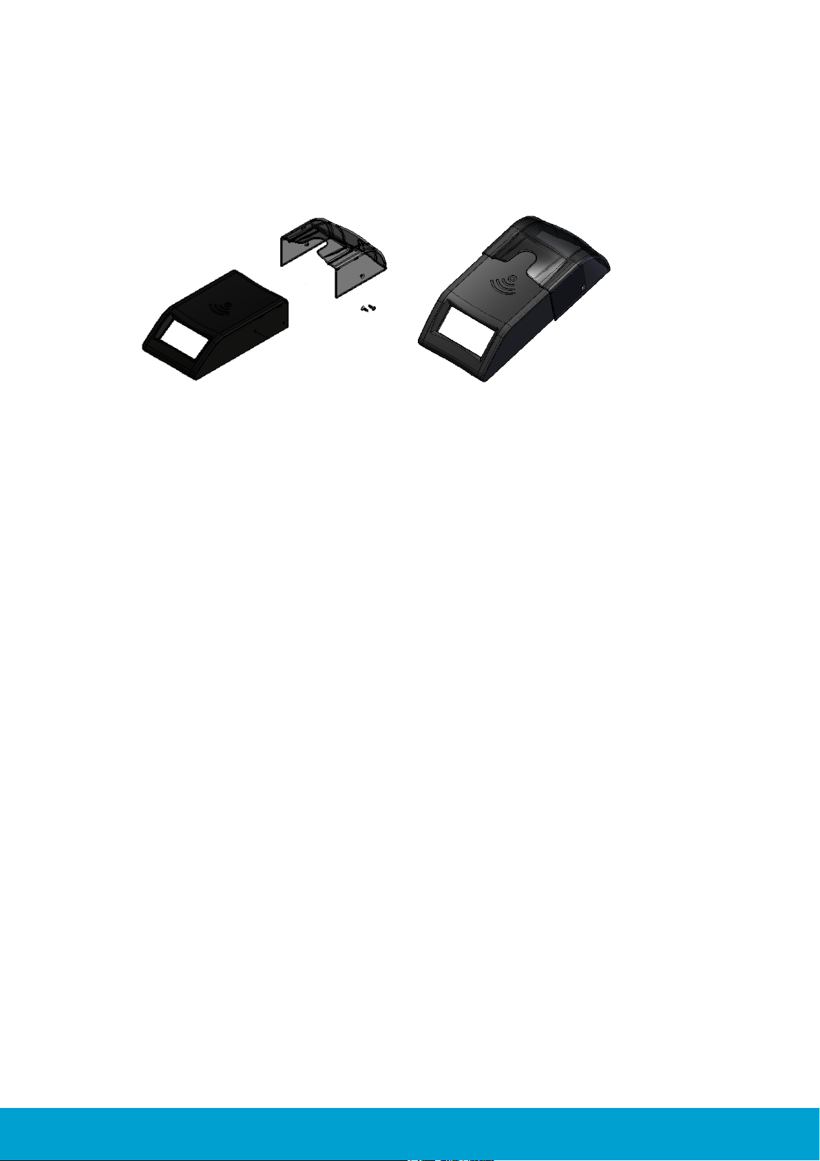
2.4 Card holder
If the RFID encoder is mounted on the wall, a card holder should be mounted on
the encoder. The card holder, including two screws for fixation, are enclosed with
the encoder at delivery.
Figure 4: The card holder is snapped onto the RFID encoder
and also fastened with two screws.
ASSA ABLOY Hospitality
9
66 1001 001-7
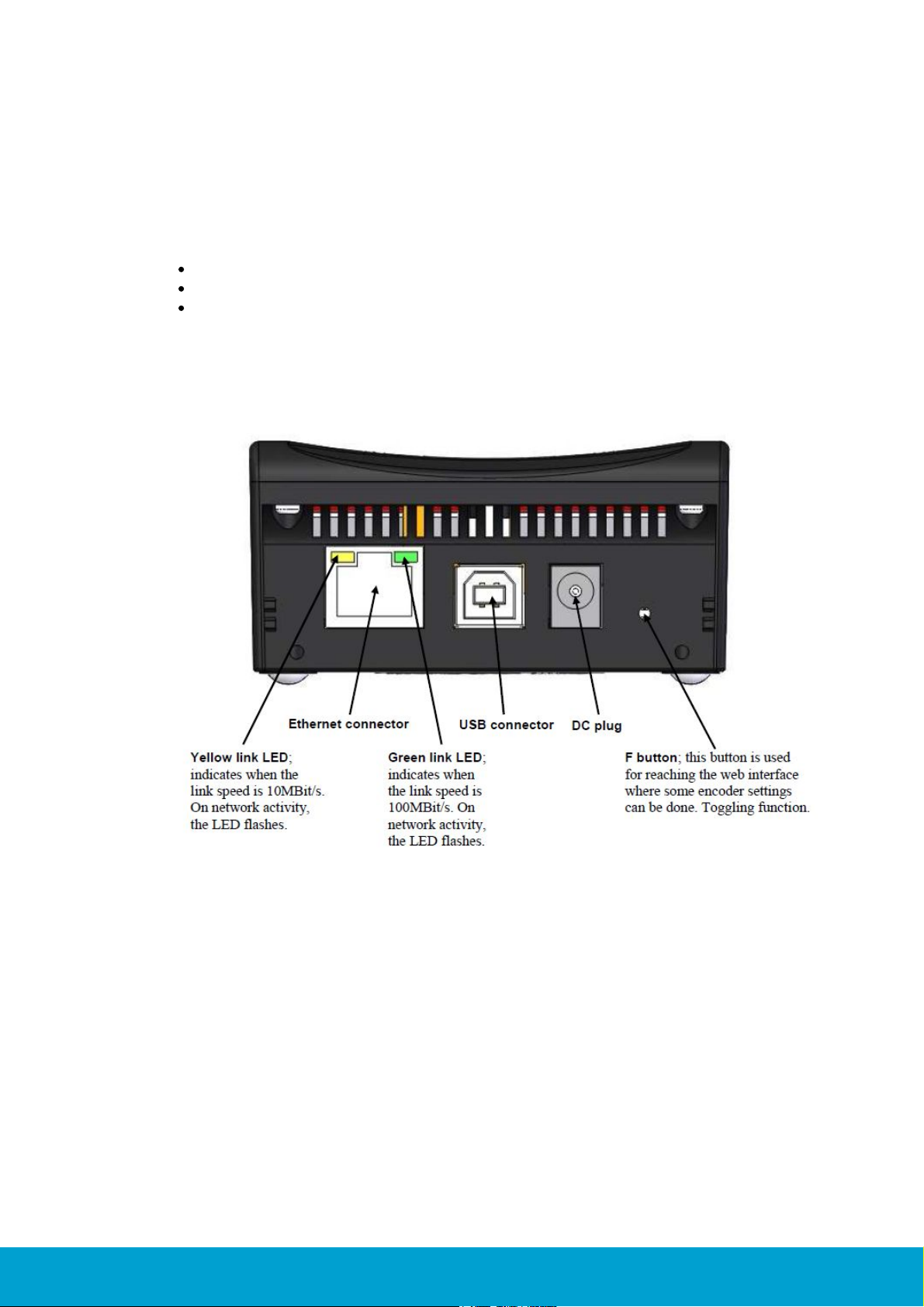
3. Electrical specification
Figure 5: Rear panel of encoder
There are several possibilities for powering:
Power via PoE; power over Ethernet
External power via adapter of 5VDC regulated voltage
Power via USB (only applicable for Visionline)
3.1 Connectors
ASSA ABLOY Hospitality
10
66 1001 001-7

4. To connect to Visionline or VingCard Vision
4.1 To connect to the Visionline server
4.1.1 To connect via TCP/IP
If the encoder connects to the server via TCP/IP, it automatically adjusts to 10
or 100Mbit/s networks. The encoder starts by retrieving an IP address via DHCP;
Dynamic Host Configuration Protocol. The encoder then automatically finds the
server.
Note: When the encoder has been detected by the server, the display shows the
date and time. An encoder device will automatically be added to the server.
If no DHCP server is available:
1. The display will show 'offline' and the encoder IP address (default 192.168.0.100,
or another IP address if the encoder has already been connected to a network).
2. Shortly after, the IP address on the encoder display will change to an
IP address in the range 169.254.1.0 – 169.254.254.255; this range is
based on the zero config standard.
Note: When the RFID encoder has got an IP address, either via DHCP or via zero
config, it makes an announcement broadcast which either the Visionline server or
a connected ZigBee gateway should answer to. For more information about how the
RFID encoder finds the server, see Appendix E.
4.1.2 To connect via USB
If the encoder should connect via USB, the following steps must be taken:
The USBXpress driver must be installed; see Appendix B for details.
An encoder device must be added to the Visionline device list;
see details here.
Note: Power via USB is not always enough for the encoder. If this is the case,
use the enclosed external power supply of 5VDC.
ASSA ABLOY Hospitality
11
66 1001 001-7

To add an encoder device in the Visionline device list:
Figure 6
1. When the USBXpress driver
has been installed according to
Appendix B, open the Visionline
device list by double clicking on
Devices under the Lists tab in
the navigation window.
2. In the Devices dialog, click Add;
the Device details dialog will
be shown.
3. Enter a Name for the encoder.
4. If desired, enter a Description
for the encoder.
5. At Type, choose 'Network
RFID encoder (USB)' in the
drop-down-menu.
Figure 7
6. At S/N, click the button. All
network RFID encoders that are
connected via USB will be shown
in the drop-down list; see Figure 7.
7. In the Device details dialog, mark
the applicable radio button under
Location. For Server and
Computer, the field PMS
address will be available;
fill in this if applicable.
8. Click Save and Close.
Figure 8
9. Double click on
RFIDEncoderConfig.exe which
is available on the Visionline CD
under Drivers/RFID Encoder/
RFID Encoder Configuration
Utility; if the encoder is correctly
connected to the PC and uses the
USBXpress driver, the serial number
of the encoder should be shown in
the upper left window at USB; see
example in Figure 8.
10.Follow the steps in section 5.1 to
make the settings in RFID Encoder
Configuration Utility.
ASSA ABLOY Hospitality
12
66 1001 001-7

4.1.3 RFID encoder in SysMon
Figure 9
1. Double click on SysMon.exe in
the Visionline installation folder.
2. Go to View/RFID Encoders;
encoders that have been connected
via TCP/IP will be shown. Note:
When hovering over an RFID
encoder in the RFID Encoders
window of SysMon, information
about Mac address, IP address,
firmware version and last ping
will be shown.
Note: For upgrade of firmware
via SysMon, see Appendix C.
4.1.3.1 To rename the encoder
Figure 10
1. To rename an encoder,
right click on it in SysMon
and choose Edit Name.
Figure 11
2. The dialog in Figure 11 will be
shown; enter a name for the
encoder and click OK.
ASSA ABLOY Hospitality
13
66 1001 001-7

4.2 To connect to the VingCard Vision server or workstation
Figure 12
1. Install the USBXpress driver according to Appendix B.
2. Double click on RFIDEncoderConfig.exe; if the encoder is
correctly connected to the PC and uses the USBXpress driver,
the serial number of the encoder should be shown in the upper
left window at USB; see example in Figure 12.
3. Follow the steps in section 5.2 to make the settings in RFID
Encoder Configuration Utility.
4.2.1 To connect via TCP/IP
To make the RFID encoder accessible for VingCard Vision, the encoder must be
assigned with four parameters:
IP address
IP port number
gateway address
subnet mask
Before setting the above parameters in RFID Encoder Configuration Utility, the
USBXpress driver must be available for the RFID encoder to be able to connect and
perform the setup. When the RFID encoder has been configured with the four
parameters above, the encoder becomes backward compatible with the KDE
encoder which connects via TCP/IP only and has a static IP address.
ASSA ABLOY Hospitality
14
66 1001 001-7

5. Configuration utility
Dynamic IP address
(DHCP)
Note: This parameter
is only applicable for
Visionline.
If this checkbox is marked, the RFID encoder retrieves
an IP address via DHCP (Dynamic Host Configuration
Protocol) and then automatically finds the server.
Host IP address
The IP address of the encoder
Subnet Mask
A mask used to determine what subnet an IP address
belongs to
Announcement
broadcast
If there is no DNS (Domain Name System), the RFID
encoder will still find the server if this checkbox is
marked
Emulate KDE
Emulate a KDE encoder
Note for Visionline: With the 'emulate KDE' alternative
marked, the web interface described in chapter 7 will not
be available.
Wall mounted
This parameter changes the text orientation on the
encoder display. Mark Enable if the encoder should
be mounted on the wall.
Zero config
Note: This parameter
is only applicable
for Visionline.
If no DHCP server is available, the encoder will at startup
show 'offline' and the encoder IP address. Shortly after,
the IP address will change to an address in the range
169.254.1.0 – 169.254.254.255; this range is based
on the zero config standard. Note: It is recommended
to always have this checkbox marked.
EPHY auto negotiate
If the link speed (10 or 100 Mbit/s) has been unaltered
for a certain time, a detector changes to manual speed
and alternatively tests 10MBit/s and 100MBit/s until
an answer is given. When this detector is activated, the
parameter EPHY (Ethernet PHYsical transceiver) auto
negotiate will be set to 'No' and the checkbox will
be unmarked.
If the encoder parameters need to be modified to suit the network where the
encoder is located, this can be done in RFID Encoder Configuration Utility.
Table 2 below describes the configurable parameters.
For guidance about how to configure the RFID encoder for use together with
Visionline, see section 5.1. For information about how to configure the RFID
encoder for use together with VingCard Vision, see section 5.2. For default
parameter values, see section 6.1.
Note: For Visionline, the parameters can also be changed via a web interface;
see chapter 7.
Table 2: Configurable parameters
ASSA ABLOY Hospitality
15
66 1001 001-7

5.1 To configure the encoder for use with Visionline
Figure 13
1. Make sure that the USBXpress driver is installed;
see Appendix B for details.
2. Double click on RFIDEncoderConfig.exe.
3. Connect the encoder to USB power; the encoder will
appear in the drop-down-menu at 'USB' in the upper
left corner of the RFID Encoder Configuration
Utility window.
4. Select the encoder in the drop-down-menu.
5. Click the Start button to connect.
Figure 14
6. Click the Get version button.
Figure 15
7. The firmware version of the encoder will be shown;
make sure that it is the latest version, if not upgrade
the encoder according to Appendix C.
ASSA ABLOY Hospitality
16
66 1001 001-7

Figure 16
8. Click the Get config button. At first configuration, the
default encoder parameters will be shown; see Figure
16. Note: The default parameter values are also shown
in section 6.1.
Figure 17
9. To modify one or more parameters, make the desired
changes and click the Set config button.
Figure 18
10.When the new configuration has bee set in the
encoder, a message as in Figure 18 will be shown.
ASSA ABLOY Hospitality
17
66 1001 001-7

5.2 To configure the encoder for use with VingCard Vision
Figure 19
1. Make sure that the USBXpress driver
is installed; see Appendix B for details.
2. Double click on RFIDEncoderConfig.exe.
3. Connect the encoder to USB power; the encoder
will appear in the drop-down-menu at 'USB' in the
upper left corner of the RFID Encoder Configuration
Utility window.
4. Select the encoder in the drop-down-menu.
5. Click the Start button to connect.
Figure 20
6. Click the Get version button.
Figure 21
7. The firmware version of the encoder will be shown;
make sure that it is the latest version, if not upgrade
the encoder according to Appendix C.
ASSA ABLOY Hospitality
18
66 1001 001-7

Figure 22
8. Click the Get config button. At first configuration, the
default encoder parameters will be shown; see Figure
22. Note: The default parameter values are also shown
in section 6.1.
Figure 23
9. Under IP Setup:
- uncheck Dynamic IP address (DHCP)
- set Host IP address; this is the
encoder IP address
- set Default gateway; this is the
encoder gateway address
- set Subnet mask; this is the
encoder subnet mask
10.Under Connection Setup:
- uncheck Announcement broadcast
- let Server IP and Server Port be
empty; these parameters are not
applicable for VingCard Vision
- let KDE port be 3001
11.Under Misc Settings:
- check Emulate KDE
- uncheck the rest of the checkboxes
12.Click the Set config button.
Figure 24
13.When the new configuration has been set in the
encoder, a message as in Figure 24 will be shown.
14.Disconnect the power and USB cables.
15.Connect the LAN cable to the local hub.
16.Power up the encoder.
ASSA ABLOY Hospitality
19
66 1001 001-7

6. To factory reset the encoder
Figure 25
1. Click the Defaults button.
Figure 26
2. If the default parameters should be set in the
encoder, click the Set config button. Note: If
VingCard Vision is applicable, it will not be possible
to connect to the encoder after the default values
have been set in it. In this case, the encoder must
then be reconfigured according to section 5.2; make
sure that Emulate KDE is checked in RFID
Encoder Configuration Utility.
There are two ways to reset the encoder parameters to default values, e.g. if an
encoder should be used at a demo installation:
Press and hold the F button with a narrow instrument while powering up the
encoder; see in Figure 5 where the button is located.
Press Defaults and then Set config in the RFID Encoder Configuration Utility;
see below for details. The default values are also shown in Table 3.
ASSA ABLOY Hospitality
20
66 1001 001-7

6.1 Default parameter values
Parameter
Default value
Dynamic IP address (DHCP; Dynamic Host Configuration
Protocol)
Enable
Host IP
192.168.0.100
Default gateway
192.168.0.1
Subnet mask
255.255.255.0
Announcement broadcast
Enable
Server port
7799
KDE port
3001
Emulate KDE
Disable
Wall mounted
Disable
Zero config
Enable
EPHY auto negotiate
Enable
Note: For a description of the encoder parameters, see Table 2.
Table 3: Default parameter values for the RFID encoder
ASSA ABLOY Hospitality
21
66 1001 001-7

7. Web interface
Figure 27
1. Press the F button down to the right on
the back of the encoder (see Figure 5);
use a narrow instrument.
2. In the web browser, enter http://
ipaddress; the IP address to enter is shown
on the display at startup of the encoder.
See example below:
Note: If no DHCP server is available, use
the zero config IP address which is shown
on the display; see section 4.1.1 for more
information about zero config.
3. Make the desired changes in the RFID
Encoder Setup page; see example in
Figure 27.
4. If the server IP should be changed and
there is no DNS (Domain Name System):
Enter the applicable Server IP, OR
mark the radio button 'Enable'
for Announcement Broadcast;
this makes the encoder find the server.
5. When all desired changes have been done
in the RFID Encoder Setup page:
- Click Save.
- Click Reboot.
- Press the F button on the encoder again
to close the web interface.
(only applicable for Visionline)
If the parameters for the RFID encoder need to be modified to suit the network
where the encoder is located, this can be done either
via the configuration utility described in section 5.1
via the web interface described in the section To modify the encoder parameters.
To open the web interface, http://ipaddress must be entered in a web browser.
The encoder IP address is shown on the encoder display. Note: See Table 2 for
a description of the encoder parameters.
7.1 To modify the encoder parameters
ASSA ABLOY Hospitality
22
66 1001 001-7

Appendix A: Quick reference of technical data
Dimensions, encoder (WxHxD):
83.3 x 152.0 x 42.2 mm (3 9/32" x 5 31/32" x 1 21/32")
Dimensions, card holder (WxHxD):
88.7 x 85.8 x 48.0 mm (3 1/2" x 3 3/8" x 1 57/64")
Material in encoder: ABS UL 94V-0
Automatic adjustment to 10 or 100MBit/s networks
Material in card holder: PC UL 94V-0, semitransparent
Several possibilities for powering:
- Power via PoE; power over Ethernet
Note: The RFID encoder is of PoE class 1; power range 0.44-3.84W.
- External power via adapter of 5VDC regulated voltage
- Power via USB (only applicable for Visionline)
The maximum current consumption for the RFID encoder is
400 mA continuously
Sound signals
Intended for indoor use only, temperature range +5ºC to +50ºC
Relative humidity 10-90%; non-condensing
Required version of Visionline: 1.11.1 or higher
Required version of VingCard Vision: 5.2 or higher
ASSA ABLOY Hospitality
23
66 1001 001-7

Appendix B: To install the USBXpress driver
Figure B1
1. All necessary files for the USBXpress
driver are found on the Visionline CD
under Drivers/USBXpress Driver;
double click on
USBXpressInstaller.exe and follow the
instructions.
2. Connect the RFID encoder by USB cable
to the computer.
3. Go to the Device Manager in Windows
and click the plus sign in front of
'Universal Serial Bus controllers'; see
Figure B1.
Figure B2
4. In the Device Manager, double click on
the USBXpress Device and make sure
that the USBXpress Device Properties
dialog says 'This device is working
properly' as in Figure B2.
ASSA ABLOY Hospitality
24
66 1001 001-7

Appendix C: To upgrade firmware
Figure C1
1. Double click on
RFIDEncoderConfig.exe.
2. Connect the encoder to USB power;
the encoder will appear in the dropdown-menu at 'USB'.
3. Select the encoder in the dropdown-menu.
4. Click the Start button.
5. Click the Open button.
Figure C2
6. Browse to the desired firmware file
and click Open.
Figure C3
7. When the firmware version has
been loaded, it will be shown next
to the Bootload button as shown
in Figure C3.
To upgrade firmware via RFID Encoder Configuration Utility
ASSA ABLOY Hospitality
25
66 1001 001-7

Figure C4
8. Click the Bootload button.
Figure C5
9. When the bootloading has finished,
a message as in Figure C5 will be
shown.
To upgrade firmware via SysMon
Figure C6
1. Double click on SysMon.exe in
the Visionline installation folder.
2. Go to View/RFID Encoders;
encoders that have been
connected via TCP/IP will be shown.
3. Mark the applicable encoder and click
the Set button; choose Set
Firmware Files for Bootloading.
Figure C7
4. The dialog in Figure C7 will
be shown.
5. Click the Browse button
at the applicable one of ’RFID
Encoder’ or ‘RFID Encoder w ext
memory’ and select the applicable
encoder firmware file.
6. Click OK in the Select Firmware
Files for Bootload dialog.
(only applicable for Visionline)
ASSA ABLOY Hospitality
26
66 1001 001-7

Appendix D: Boot-up procedure
1. When an encoder comes out of reset, it reads its IP configuration
from a non-volatile memory.
2. If 'Dynamic IP Address' is set to Disable (see chapter 7): the encoder
sets its IP address to the address stored in the config memory. Continue at
step 13 below.
3. If 'Dynamic IP Address' is set to Enable (see chapter 7): the encoder
sends a DHCP Request packet with IP destination address 255.255.255.255,
i.e. IP broadcast, requesting its most recently used IP address.
4. If the network/subnet configuration has not changed, the DHCP server will
most likely send a DHCP ACK packet, allowing the encoder to continue to
use the same IP. The DHCP server may use either IP broadcast or unicast for
this packet; broadcast is however most commonly used. Continue at step 10
below.
5. If the DHCP server is unwilling to let the encoder use the same address as
before, or if the requested IP is out of scope, it sends a DHCP NAK.
6. The encoder resets its IP address to 0.0.0.0 and sends a DHCP Discover packet
with IP destination address 255.255.255.255; IP broadcast.
7. If a DHCP server is available, it sends a DHCP Offer packet. Since the encoder
has no valid IP address, the DHCP server must send to IP destination
255.255.255.255; IP broadcast.
8. The encoder receives the offer and sends a DHCP Request packet, as in step 3
above, but this time requests the IP address offered by the DHCP server.
9. The DHCP server sends a DHCP ACK packet, confirming that the encoder may
start using the new IP address. Unlike the ACK in step 4 above, this ACK
packet must be sent to IP destination address 255.255.255.255 (IP broadcast),
since the encoder has not got any confirmed IP address yet.
10.The encoder performs gratuitous ARP (Address Resolution Protocol) to ensure
that no other host has got the same IP.
11.If IP collision is detected, the encoder sends a DHCP Decline packet which
refuses the assigned IP address and restarts the IP acquirement procedure for
the encoder.
12. New functionality, RFID encoder version 2.0.0 and later: If there is no DHCP
server available on the subnet, the encoder self-assigns an IP address from the
IPv4 Local Link address space (169.254.0.0/16), and sends gratuitous ARP to
ensure that no other host has got the same IP.
13. The encoder reads the most recently used Visionline server IP address and
tries to open a TCP connection to the server.
14. If the TCP connection attempt fails, the encoder will continue to try
connections to the same IP over and over again – unless it detects that the
network/subnet setup has changed, e.g. the encoder may have been moved to
a new location. Then it will send an application specific service discovery
request (announcement broadcast) with IP destination address
255.255.255.255; IP broadcast.
14 b. New functionality, RFID encoder version 2.0.0 and later: Even if the
network/subnet setup is unchanged, but long time (one hour) has elapsed
ASSA ABLOY Hospitality
27
66 1001 001-7

without any successful TCP connection with the Visionline server, the encoder
will start sending service discovery requests.
15. If a Visionline server is on the same subnet, or if another encoder with a valid
TCP connection to the server is on the subnet, they will send a reply to the
querying unit, letting it know the IP address and TCP port of the Visionline
server. The encoder then tries TCP connection to that IP.
15 b. New functionality, RFID encoder version 2.0.0 and later: From the payload
supplied in the reply (the reply is sent with IP destination address
255.255.255.255, IP broadcast), the querying unit can determine if its own IP
address properties are correct with respect to network class, default encoder IP
and subnet mask. If required, it will self-assign a new IP address within the
subnet specified in the reply, and then send gratuitous ARP to ensure that no
other host has got the same IP. Then it goes on and tries TCP connection to the
received server IP address.
16. New functionality, RFID encoder version 2.0.0 and later: Prior to sending the
service discovery request, the encoder tries to contact a DNS server (Domain
Name System), with a request for resolving the most recently used server host
name. If that name is unknown to the DNS, the encoder tries to resolve the
factory default server host name. If any of the two names renders a successful
DNS reply, the encoder uses the IP address received from the DNS server, and
tries TCP connections to that address. If the factory default name is unknown
too, or if a DNS server is not available at all, the encoder sends a service
discovery request.
Note: 14/14 b, (15/15b) and 16 will go on in a round robin way until the encoder
has reached the server.
ASSA ABLOY Hospitality
28
66 1001 001-7

Appendix E: More about how the encoder finds the server (Visionline only)
Introduction
This appendix describes the process of how the encoder finds the server. The solution is
based on DNS (Domain Name System) as well as on announcement broadcast, which is a
proprietary implementation of zero config; see section 4.1.1 for details about zero config.
Note: For more information about setting up DNS entries etc, contact the hotel IT
department. A general description of this cannot be made in this document, since this
varies with the type of DNS server that is used.
There are three challenges when the encoder is connected to the network:
1. A new encoder must be able to find the server even if it is located on a
separate subnet.
2. The encoder must be able to locate a backup server in case the primary server
fails. The backup server is assumed to have the latest database from the
primary server.
3. The above must be fulfilled even if there are multiple Visionline servers on the
same network.
To commission encoders:
Single server - to commission encoders with DNS
Multiple servers - to commission encoders with DNS
To commission encoders without DNS
To switch to backup server
Single server - to switch to backup server with DNS
Multiple servers - to switch to backup server with DNS
To switch to backup server without DNS
ASSA ABLOY Hospitality
29
66 1001 001-7

To commission encoders with DNS
Figure D1
If the encoder is located on the same subnet as the server, the encoder will
locate the server using announcement broadcast without any need for manual
configuration. However, the normal case is that the server and the encoder are
located on different subnets. The first encoder for each subnet requires help
from the DNS to locate the server.
Single server
1. Add a DNS entry called timeloxserver and let its IP address be the address of
the Visionline server to which the new encoder shall connect. The encoder will
then make a DNS query using the name timeloxserver and in this way get the
IP address of the server.
2. Connect the encoder to Ethernet and wait for it to appear in the SysMon
ZigBee tree.
Multiple servers
In the steps below, it is necessary to know the Visionline system code. To find it,
double click on System settings under Reports in the Visionline navigation window.
1. For each Visionline server, add a new DNS entry with the system name for
the concerned server. The system name is timelox_12-character system code
without dashes, e.g. timelox_D124BD233D13.
2. In order to find the correct server at first installation, the encoders must be
installed for one server at a time.
3. Let timeloxserver refer to the IP address of the first Visionline server.
4. When all encoders have been installed for one server, the DNS entry for
timeloxserver must be changed to the IP address of the next server.
5. When all encoders for the last server have been installed, the timeloxserver
entry must be removed.
Note: Every set of encoders that is connected with a particular Visionline server will
receive the system name of that server, once connection to the server is established.
If an encoder for some reason needs to use DNS again in the future, the system
name (e.g. timelox_D124BD233D13) will "win" over the default name. When the
encoder makes a DNS request, the system name will connect it to the correct
Visionline server.
ASSA ABLOY Hospitality
30
66 1001 001-7

To commission encoders without DNS
1. Connect one encoder to each subnet. Use the web interface for the encoder to
configure the IP address of the Visionline server; see chapter 7 for details.
Note: This is only needed for the first encoder for each subnet, since the other
encoders on the same subnet will retrieve the server IP address from the first
one by announcement broadcast.
2. Continue adding encoders. They will automatically obtain the IP address
of the Visionline server from the encoders on the same subnet that are already
online with the server.
To switch to backup server
Single server - to switch to backup server with DNS
1. Change the IP address of the timeloxserver entry in the DNS so it points to
the backup server. The encoders will then connect to the backup server if
the connection to the primary server is lost and cannot be re-established.
Multiple servers - to switch to backup server with DNS
1. For the concerned Visionline server, change the IP adress of the system name
entry in the DNS so it points to the backup server. The encoders will then
connect to the backup server if the connection to the primary server is lost and
cannot be re-established.
To switch to backup server without DNS
1. Remove the primary server from the network.
2. Assign the IP address of the primary server to the backup server
OR
Enter the IP address of the backup server in the web interface for one encoder
per subnet. Note: It will take one hour after the primary server closes its
sockets until the rest of the encoders enable their announcement broadcast.
ASSA ABLOY Hospitality
31
66 1001 001-7

Revision history
Date
Change
By
March 8, 2012
Initial version
KG
April 13, 2012
Updated section Connecting via TCP/IP
Updated section Mounting kit
KG
October 17, 2012
Updated section Connecting via TCP/IP
Added information about the USBXpress driver
Updated screenshot 'Select Firmware Files for
Bootload'
Added information about configuration utility
Updated web interface
Added chapter about reset
Updated Quick reference of technical data with
information about PoE class 1 and maximum
current consumption for the encoder
Removed information about bootloader tool
Added appendix More about how the RFID
encoder finds the server
KG
January 25, 2013
'Emulate KDE' is now implemented
KG
July 3, 2013
Added information about VingCard Vision
KG
January 13, 2014
Modified chapter about web interface
Modified chapter about installing USB Xpress
driver
Added chapter about boot-up procedure
KG
December 21, 2015
Updated layout
KG
ASSA ABLOY Hospitality
32
66 1001 001-7

ASSA ABLOY Hospitality APAC
E-mail: apac.hospitality@assaabloy.com
Phone: +65 6305 7670
ASSA ABLOY Hospitality EMEA
E-mail: emea.hospitality@assaabloy.com
Phone: +47 69 24 50 00
ASSA ABLOY Hospitality North America
E-mail: northam.hospitality@assaabloy.com
Phone: +1 972 907 2273
ASSA ABLOY Hospitality Latin America
E-mail: lam.hospitality@assaabloy.com
Phone: +52 55 36 40 12 00
www.assaabloyhospitality.com
ASSA ABLOY Hospitality
33
66 1001 001-7
 Loading...